

Why Worn Extruder Screw Repair Demands a Complete Strategy
Imagine pulling a screw from your extruder, measuring the flights, and discovering that just 0.030 inches of radial wear has quietly slashed your production output by more than half. It sounds extreme — but that kind of loss is well-documented across both extrusion and injection molding operations. The real problem? Most processors don't catch the wear until scrap rates spike or energy bills balloon out of control. And when they finally act, they often treat the repair as a one-step fix rather than the multi-stage engineering challenge it truly is.
What Is Worn Extruder Screw Repair
Worn extruder screw repair is the restoration of an extrusion screw's original geometry and surface properties after operational wear has degraded critical dimensions beyond acceptable tolerances. In practical terms, that means rebuilding flight outside diameters (OD), correcting root depth deviations, restoring flight radii, and reapplying wear-resistant surface treatments — all to bring a plastic extruder screw back to OEM-level performance.
The dimensions at stake here are precise. Flight OD clearance relative to the barrel bore controls pumping efficiency and melt seal integrity. Root depths govern channel volume, which directly affects melting capacity and output consistency. When these measurements drift, you'll notice rising melt temperatures, inconsistent product quality, and a throughput decline that machine parameter adjustments can only partially mask. As Plastics Technology has reported, even minor radial clearance increases lead to leakage flow that forces higher RPM, greater energy consumption, and diminished melt quality — a compounding spiral that accelerates both screw and barrel degradation.
Why Every Plastics Processor Should Understand the Full Repair Lifecycle
Here's the challenge: most resources available online cover only a fragment of the repair process. Some focus exclusively on hardfacing techniques. Others jump straight to vendor quotes without helping you determine whether your extruder screws are even candidates for rebuilding. Very few connect root cause analysis to alloy selection, or explain what happens after the repaired screw goes back into the barrel.
This guide takes a different approach. It's built for process engineers, maintenance managers, and plant operators who need the complete picture — not a sales pitch. You'll walk through every stage of the repair lifecycle:
- Diagnosis — measurable criteria for determining when a screw is worn and how severe the damage is
- Root Cause Analysis — classifying wear types and identifying the material and mechanical factors driving them
- System Evaluation — why the screw and barrel must be assessed together, not in isolation
- Repair Method Selection — a data-driven framework for choosing between rebuild and replacement
- Process Walkthrough — the actual step-by-step repair sequence from inspection through final finishing
- Quality Verification — post-repair dimensional checks, runout standards, and break-in protocols
- Prevention — operational practices and monitoring routines that extend the life of every repair investment
Whether you're running a single-screw extruder processing commodity polyolefins or managing a fleet of injection molding machines handling glass-filled engineering resins, the principles here apply. The goal is straightforward: equip you with the knowledge to diagnose accurately, choose wisely, and ensure that your next screw repair actually lasts.
That starts with knowing exactly what to measure — and what those numbers really tell you about the condition of your screw.
How to Diagnose Screw Wear With Measurable Criteria
A gut feeling that something is wrong with your extruder screw barrel system isn't a diagnosis — it's a guess. And guesses lead to premature rebuilds on screws that still have life, or worse, delayed action on screws that are hemorrhaging production capacity right now. Reliable diagnosis requires specific measurements, clear threshold values, and a disciplined interpretation method that connects numbers on a micrometer to real-world processing consequences.
Flight OD Clearance Thresholds and What They Mean
The single most important measurement in screw wear assessment is the radial clearance between the screw flight outside diameter (OD) and the barrel inside diameter (ID). This gap — sometimes called the flight land clearance — functions as the melt seal in your extruder. When it's tight, the screw efficiently conveys and pressurizes material. When it widens, pressurized melt leaks backward over the flights, generating excessive shear heat and slashing output.
To capture an accurate picture of your screw and barrel condition, you'll need to measure several dimensional characteristics at defined intervals along the screw's length. Davis-Standard's maintenance guidelines recommend numbering every flight, photographing each section with a tape measure for reference, and recording every reading in a spreadsheet for direct comparison against original OEM dimensions.
| Measurement Type | What It Reveals | Tools Required | Tolerance Guidance |
|---|---|---|---|
| Flight OD (outside diameter) | Radial clearance with barrel; pumping efficiency and melt seal integrity | OD bar micrometer (modified with a parallel bar spanning two flights) | Diametrical wear varies by screw size; OEM specs define low, medium, and high wear thresholds per diameter range |
| Root depth (channel depth) | Channel volume in feed, transition, and metering zones; melting and conveying capacity | Depth micrometer or caliper with depth rod | Deviation from OEM channel depth indicates localized erosion; compare across zones to isolate wear location |
| Flight width | Structural integrity of the flight land; resistance to further wear | Caliper or micrometer | Significant narrowing of flight width signals advanced wear; replacement may be preferred over rebuild |
| Flight radii (leading and trailing edges) | Material flow characteristics; risk of hang-up or degradation in transition areas | Radius gauge set | Radii should match OEM profile; sharp or irregular edges indicate adhesive or abrasive wear damage |
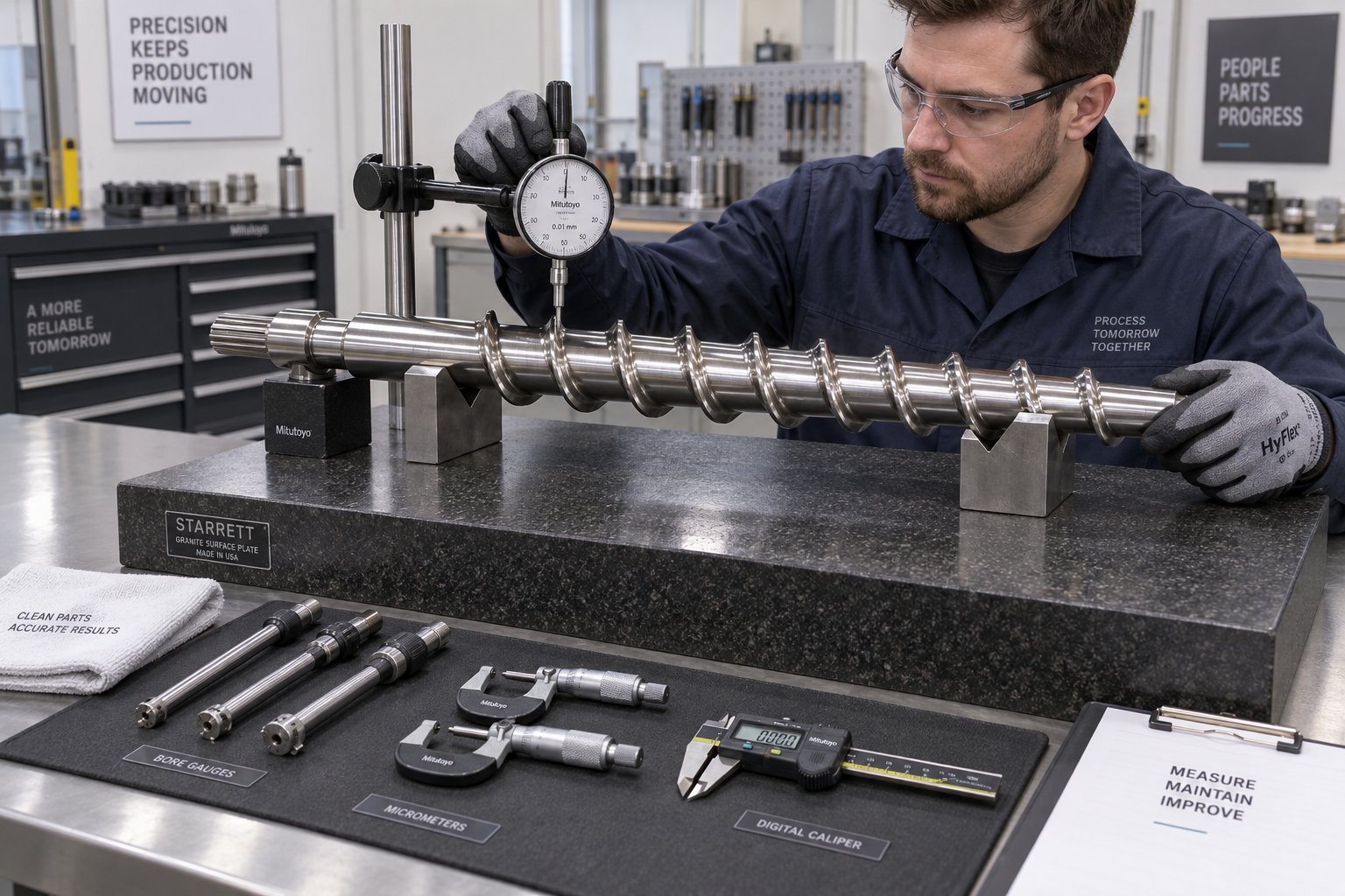
| Straightness and runout | Shaft alignment; risk of uneven barrel wear and metal-to-metal contact | Granite surface table or V-blocks with dial indicator; lathe between centers | Bowing beyond OEM tolerance causes accelerated localized wear and must be corrected before any rebuild |
A critical detail many processors overlook: all residue must be removed from the screw before measuring. Industry best practice calls for brass tools and copper gauze — never steel wire brushes or aggressive abrasives, which can scratch the flight surfaces and distort your readings. Let the screw cool completely to room temperature before taking any measurements, since thermal expansion will skew results.
Interpreting Micrometer and Bore Gauge Readings
You've got a spreadsheet full of flight OD numbers. What do they actually mean?
Start by plotting flight number versus measured OD on a simple chart, overlaying the original OEM diameter as a reference line. This visual approach — recommended in Davis-Standard's feedscrew maintenance protocol — immediately reveals whether wear is uniform along the screw length or concentrated in specific zones.
Here's how to read the pattern:
- Uniform wear across the entire screw length: Typically indicates abrasive wear from filled resins or mineral-loaded compounds. The entire flight OD profile drops evenly, and barrel wear measurement usually confirms a matching pattern in the bore.
- Heavy wear concentrated in the metering zone: Suggests the highest-pressure section of the screw is losing its melt seal. You'll often see this paired with rising melt temperatures and an inability to build adequate die pressure.
- Feeding zone wear with relatively healthy metering flights: Often points to adhesive wear from metal-to-metal contact, possibly caused by misalignment, a bent screw, or running with insufficient feed to keep the screw "floating" on a polymer layer.
- Localized pitting or gouging in the transition zone: Can signal corrosive attack from chemically aggressive resins, or damage from tramp metal contamination.
Root depth deviations add another diagnostic layer. If the channel depth in the metering zone has increased beyond OEM spec, the screw's compression ratio has effectively changed — meaning you're no longer melting and pressurizing material the way the original design intended. A channel depth increase in the feed zone, on the other hand, reduces solids conveying efficiency and can cause feed inconsistencies before the material ever reaches the melting section.
For barrel wear measurement, a bore gauge inserted from each end of the barrel captures the ID at multiple points. Adams Engineers notes that comparing bore gauge readings to previous inspection values over time creates a wear profile, allowing you to predict service windows rather than react to failures. The SPI Dimensional Guidelines provide reference thresholds for when a component is too worn for continued use.
Output Loss as a Leading Indicator
Here's something experienced operators know but rarely document formally: the process data on your control panel often signals screw wear long before a micrometer confirms it. Treating output loss and thermal anomalies as leading indicators — rather than waiting for a scheduled pull-and-measure — can save you weeks of running in a degraded state.
Watch for these warning signs during normal production:
- Declining throughput at constant RPM: If you need to increase screw speed to maintain the same output you achieved six months ago, radial clearance has likely widened. Industry diagnostic data shows that a die head pressure drop exceeding 15% at the same RPM and feed rate strongly indicates metering zone flight wear.
- Melt temperature exceeding setpoint despite heaters at zero output: When barrel zone temperatures stubbornly climb above your profile — say, you set 200°C but actual reads 215°C — and cooling fans are running at maximum, excessive shear heat from worn clearances is the likely culprit. The enlarged gap forces melt through an intense friction zone, generating heat that the barrel's thermal management system cannot overcome.
- Motor torque and current dropping below historical baselines: This one is counterintuitive. A 10-20% drop in drive torque at the same RPM and material doesn't mean your machine is running more efficiently. It means the screw is losing its grip on the polymer — material is slipping past worn flights instead of being compressed and conveyed forward.
- Wild pressure fluctuations at the die: Stable melt pressure produces consistent product dimensions. When die pressure oscillates erratically rather than showing the normal minor fluctuations, the metering and homogenization zones can no longer maintain a uniform melt seal.
Any single indicator warrants investigation. Two or more occurring simultaneously should trigger an immediate inspection protocol — pull the screw, measure every flight, and compare against your baseline documentation. The cost of a planned shutdown for measurement is trivial compared to the compounding damage of running a worn screw: degraded product quality, elevated energy consumption, and accelerated barrel erosion that turns a simple screw rebuild into a far more expensive system overhaul.
Knowing that a screw is worn, however, is only half the equation. The critical next step is identifying what type of wear has occurred — because the dominant wear mechanism dictates everything from alloy selection to whether a repair will hold up or fail within months.
Types of Screw Wear and Their Root Causes
A set of dimensional readings tells you how much material is gone. It doesn't tell you why it disappeared. And that distinction is everything when choosing a repair approach. Rebuilding a screw with the wrong hardfacing alloy because you misidentified the wear mechanism is one of the most common reasons repairs fail prematurely — sometimes in a fraction of the time the original screw lasted. Accurate classification of extruder screw wear types is the bridge between diagnosis and a repair that actually holds.
Adhesive, Abrasive, and Corrosive Wear Explained
Three dominant mechanisms account for virtually all screw degradation in plastics processing. Each leaves a distinct fingerprint on the metal surface, affects specific screw zones differently, and responds to different repair strategies.
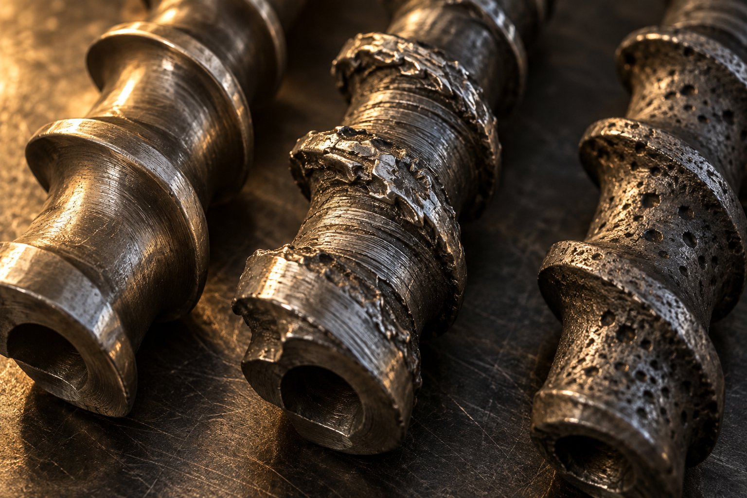
Adhesive wear happens when two metal surfaces slide against each other under high compressive force, causing material to transfer from one surface to the other. Imagine the flight OD pressing directly against the barrel wall with no polymer film in between. The friction generates enough heat and pressure to micro-weld tiny fragments of flight material onto the barrel — and vice versa. Plastics Technology describes this as galling: metal is pulled, torn, and friction-welded between the contacting surfaces, leaving gouged areas with balled-up or torn lumps stuck to the flight lands. In single-screw extruders, this often results from wedging in the compression zone — where a slug of unmelted polymer creates an unbalanced radial force that shoves the screw against the barrel wall. Misalignment, bent shafts, or gearbox damage can produce similar metal-to-metal contact anywhere along the screw length.
Abrasive wear is the most common extruder screw wear type across the industry. It results from hard particles grinding against the screw's machined surfaces, gradually eroding flight ODs, roots, and radii. Glass fibers, calcium carbonate, titanium dioxide, mineral fillers, and even recycled feedstock containing contaminants all act as tiny cutting tools. As industry experts note, the amount of filler present and particle shape strongly influence abrasive intensity — larger particles with sharper corners wear far more aggressively than smaller, rounder ones. Visually, abrasive wear extruder screw surfaces appear smooth, rounded, and occasionally polished where sharp machined corners once existed. Xtrutech's field data confirms this pattern in twin-screw applications as well: sharp edges on screw and kneading elements progressively round off, and the rate of material loss correlates to production volume rather than calendar time.
Corrosive wear stems from chemical attack by the polymer or its degradation byproducts. PVC processing is the classic example — when rigid PVC overheats, it releases hydrochloric acid that aggressively pits and erodes metal surfaces. Fluoropolymers, flame-retardant compounds, and certain acetals produce similarly reactive byproducts at elevated temperatures. The surface of a corroded screw looks distinctly different from an abraded one: instead of smooth, polished erosion, you'll see dimpled or pitted surfaces resembling chemical etching. Corrosive wear in plastics processing can also develop from unexpected sources — condensation forming on chilled barrel sections, for example, can initiate surface corrosion that compounds over time.
The following taxonomy maps each mechanism to its practical characteristics and the repair direction it demands:
| Wear Type | Common Causes | Visual Characteristics | Affected Screw Zones | Recommended Repair Approach |
|---|---|---|---|---|
| Adhesive | Metal-to-metal contact from misalignment, bent screw/barrel, wedging due to inadequate melting, running screws without polymer lubrication | Galling marks, torn or balled-up metal on flight lands, burrs on trailing edge (wedging) or both edges (misalignment) | Compression/transition zone (wedging); anywhere along length (misalignment) | Correct the mechanical root cause first; rebuild flights with galling-resistant, high-hardness hardfacing alloys |
| Abrasive | Glass-filled resins, mineral fillers (CaCO3, talc, TiO2), recycled/contaminated feedstock, tramp metal | Smooth, rounded, polished flight edges; gradual OD reduction; root erosion on forwarding side of flights | Feed zone (with fillers introduced at the throat); transition and metering zones (highest pressure regions) | Tungsten carbide or high-hardness cobalt-based hardfacing; consider downstream filler addition to reduce solids-zone exposure |
| Corrosive | PVC and its HCl byproducts, fluoropolymers, flame-retardant compounds, acetals, condensation on chilled barrel sections | Pitting, dimpling, chemical etching on surface; uneven material loss not following pressure distribution pattern | Metering zone (highest melt temperature); any zone where chemical exposure or condensation is concentrated | Nickel-based or corrosion-resistant alloy hardfacing; address temperature control and purging practices to reduce chemical exposure |
How Processing Materials Drive Wear Patterns
Here's what makes worn extruder screw repair so challenging to get right: the same screw design running in the same machine can wear in completely different ways depending on what material you're processing. A screw worn by glass-filled nylon demands a fundamentally different hardfacing alloy than one degraded by corrosive PVC compounds. Choosing the wrong alloy — even a technically excellent one — because you didn't account for the dominant wear mechanism is a recipe for a repair that fails in half the expected service life.
Consider the contrast. An injection molding feedscrew running 30% glass-filled PA66 will experience severe abrasive wear, concentrated in the feed section where dry, unmelted pellets are being conveyed under pressure with limited lubrication. Experienced screw manufacturers report that this is precisely why many processors add fillers downstream where the polymer is already molten — the melt provides lubrication that dramatically reduces solids-zone erosion. The repair for this screw needs maximum abrasion resistance: tungsten carbide composites or similarly hard coatings that can withstand the relentless grinding of sharp glass fibers.
Swap that same machine over to processing rigid PVC, and the wear profile changes entirely. The concern shifts from mechanical grinding to chemical degradation. Even a slight temperature excursion can trigger HCl generation, which attacks base metal and hardfacing alike. A tungsten carbide coating that excels against glass fibers may have poor resistance to acid-driven corrosion. The correct repair here involves nickel-based alloys specifically engineered for chemical resistance in corrosive environments.
Processors running multiple materials through the same equipment face an even more complex decision matrix. A screw that processes both filled and unfilled compounds on alternating production runs needs a hardfacing solution that balances abrasion and corrosion resistance — typically a cobalt-based alloy family that offers reasonable performance across both wear mechanisms without excelling at either extreme.
Combined and Accelerated Wear Scenarios
Real-world screw wear rarely fits neatly into a single category. More often, two or even all three mechanisms overlap — and their combined effect is far more damaging than the sum of individual contributions.
Misalignment is one of the most common accelerators. When the barrel bore and screw axis aren't concentric, the screw deflects to conform to the barrel — the barrel's higher moment of inertia always wins, as extrusion engineer Jim Frankland explains. This creates adhesive wear from metal-to-metal contact on top of whatever material-driven wear is already happening. Misalignment coupled with a glass-filled resin, for instance, produces both adhesive galling and aggressive abrasive erosion simultaneously. The visual evidence becomes harder to read because two patterns overlap, but the telltale sign is flight wear that combines smooth, polished erosion in some areas with torn, galled surfaces in others — often on the same flight.
Excessive back pressure is another compounding factor. Higher pressures in the metering zone intensify friction between the polymer-flight-barrel interface, accelerating both adhesive and abrasive wear rates. Abrasion testing across multiple industries consistently shows that increased pressure and temperature together lead to elevated friction — which is exactly why the transition section and final metering turns typically see the worst wear on any screw.
Improper temperature profiles add a third layer. Running barrel zones too hot in a PVC application doesn't just increase corrosive attack — it also softens the flight surface, reducing its resistance to abrasive particles in the compound. Running too cold in the feed section of a crystalline resin can cause incomplete melting, leading to the wedging phenomenon that triggers sudden, catastrophic adhesive wear in the compression zone.
The practical takeaway? When you pull a screw and see wear that doesn't fit a clean single-mechanism pattern, step back and evaluate the full operating context: material, temperatures, pressures, alignment history, and production patterns. Identifying the dominant mechanism — the one doing 60-80% of the damage — is what determines the best hardfacing alloy and application method for the repair. Getting it wrong means the rebuilt screw wears out the same way, or worse, even faster than the original.
Of course, the screw is only half of a precision clearance system. Even a flawlessly rebuilt screw will underperform — or re-wear prematurely — if the barrel it slides into has its own dimensional problems waiting to undermine the investment.
The Screw-Barrel System: Why Extruder Screws and Barrels Must Be Evaluated Together
A rebuilt screw doesn't operate in a vacuum — it operates inside a barrel. And that barrel has been wearing right alongside the screw, often at a rate that goes unnoticed because processors focus all their attention on the more accessible component. This blind spot is responsible for more failed repairs than any single metallurgical mistake or machining error.
Why a Worn Screw Cannot Be Evaluated in Isolation
Think of the screw flight OD and the extruder barrel bore ID as two halves of a precision seal. Under normal operating conditions, the radial clearance between them is remarkably tight — typically 0.001 inch per side for every inch of screw diameter. On a 2.5-inch extruder, that means just 0.0025 inches of clearance per side separates the flight land from the barrel wall. That narrow gap is what enables efficient pressure generation, consistent melt sealing, and uniform heat transfer from barrel to polymer.
When wear opens up this clearance — whether on the screw side, the barrel side, or both — pressurized melt leaks backward over the flights. You lose pumping efficiency. Melt temperature rises from excessive shear. Output drops. Spending thousands of dollars to restore perfect flight geometry on the screw while ignoring a barrel bore that's enlarged, ovalized, or locally eroded simply recreates an oversized clearance from the barrel side of the equation.
Repairing one component while ignoring the other is the most common and costly mistake in extruder maintenance. A perfectly rebuilt screw inside a worn barrel delivers the same poor performance — and accelerates re-wear of the new hardfacing.
The physics are straightforward. A rebuilt screw with a fresh, tight-tolerance flight OD spinning inside an enlarged bore still allows leakage flow. Worse, if the barrel is worn unevenly — tapered, ovalized, or locally eroded — the screw won't ride concentrically. That off-center rotation creates the same metal-to-metal contact and adhesive wear patterns discussed earlier, chewing through your new hardfacing in a fraction of the expected service life.
Barrel Inspection Essentials for Screw Repair Decisions
Barrel inspection is simpler than screw measurement, but it demands the same disciplined approach. Using a bore gauge, measure the extruder barrel ID as far down each end as the gauge can reach — and at multiple intermediate points if the barrel length allows access. Adams Engineers recommends recording these readings and comparing them against both OEM specifications and previous inspection values to track wear progression over time.
You're looking for three things: overall enlargement, taper, and ovality. Overall enlargement tells you the barrel's general wear state. Taper — where the bore is larger at one end than the other — suggests material-driven erosion concentrated in specific processing zones. Ovality — a bore that's no longer perfectly round — points to misalignment or uneven thermal loading that has deformed the barrel cross-section.
Any of the following conditions should trigger concurrent barrel service alongside your screw repair:
- Bore diameter exceeding OEM tolerance — even if the screw is being rebuilt, an out-of-spec barrel negates the investment
- Visible corrosion pitting on the bore surface — pits create localized flow disruptions and accelerate screw flight wear at those points
- Uneven wear patterns suggesting misalignment — a barrel worn more heavily on one side indicates the extrusion barrel and drive system need alignment correction before any rebuilt screw is installed
- Residual liner thickness below safe limits — bimetallic extrusion barrel liners are typically only 0.060 inches thick from the factory; significant bore enlargement means the hardened liner is thinning, reducing both its hardness and protective capability
One detail that often catches maintenance teams off guard: if your barrel has pressure transducer ports located in zones where the screw flights rotate, bore enlargement can expose the transducer tip to direct contact with the screw. Industry case data shows that even 0.015 inches of bore enlargement per side can cause the transducer to protrude into the screw's flight path — destroying an expensive sensor and potentially damaging the rebuilt screw on its very first run.
Matching Screw Repair Specifications to Current Barrel Condition
Here's where practical engineering judgment matters most. The flight OD on a rebuilt screw should be sized to the actual barrel bore — not automatically restored to original OEM dimensions. If the barrel has experienced minor, uniform wear that remains within acceptable clearance limits when paired with a correctly sized screw, rebuilding to the actual bore diameter is the technically sound approach.
Some repair shops offer an alternative: honing the barrel oversize and rebuilding the screw oversize to match, maintaining original clearances with larger components. Sounds logical on the surface, but screw design engineers caution strongly against this practice, especially on smaller extruders. Oversizing a 2.5-inch screw by 0.030 inches increases the metering channel depth by roughly 10% — enough to significantly reduce pumping capacity, particularly with low-viscosity resins. Mixing sections suffer too: barrier land clearances widen, shear rates drop, and you end up with unmelts and poor color distribution that no process adjustment can fully correct.
The decision matrix looks like this:
| Barrel Condition | Recommended Screw Repair Approach | Cautions |
|---|---|---|
| Within OEM tolerance | Rebuild screw to original OEM flight OD specifications | Verify bore at multiple points to confirm uniform condition |
| Minor uniform wear, still within functional clearance when paired with rebuilt screw | Rebuild screw flight OD to match actual barrel bore, maintaining proper radial clearance | Document actual barrel ID so the repair shop can target the correct flight OD |
| Moderate wear, approaching or exceeding clearance limits | Replace or reline the barrel; rebuild screw to the new barrel's bore specifications | Rebuilding the screw alone will not restore performance; concurrent barrel service is mandatory |
| Ovalized or tapered bore | Replace or reline barrel before rebuilding the screw | No screw geometry can compensate for a non-round or tapered bore; alignment must also be corrected |
The key takeaway is communication. When you send a screw out for repair, always include current barrel bore measurements taken at multiple points along the extrusion barrel length. A repair shop working without this data is guessing at the flight OD target — and a guess, no matter how experienced, is not engineering. Providing actual barrel dimensions ensures the rebuilt screw and its mating barrel form the tight, concentric clearance system that makes the whole plasticating unit function as designed.
With a clear picture of both screw and barrel condition in hand, the next question becomes unavoidable: does this screw warrant the investment of a full rebuild, or has it reached the point where replacement makes more economic and engineering sense?
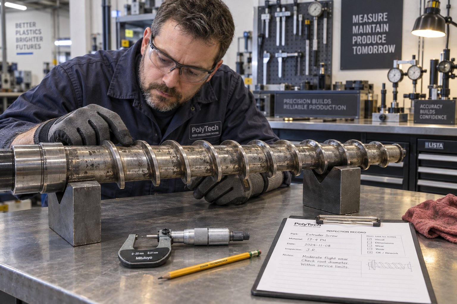
Screw Repair vs Replacement: A Data-Driven Decision Framework
Every maintenance manager who has stared at a worn screw on a shop table has faced the same internal debate: rebuild it or buy new? The temptation is to default to whichever option is cheaper upfront — but that instinct routinely leads to the wrong call. A screw that gets rebuilt when it should have been replaced wastes repair dollars and fails early. A screw that gets scrapped when a quality rebuild would have delivered years of additional service wastes capital and extends downtime waiting for a new one. The difference between a good decision and a costly mistake comes down to evaluating the right variables — systematically, not emotionally.
Key Variables in the Repair or Replace Decision
Screw repair vs replacement isn't a single yes-or-no question. It's a matrix of interrelated factors, and the answer shifts depending on your specific situation. The following framework organizes the critical variables you need to evaluate before committing to either path.
| Variable | Favors Repair | Favors Replacement |
|---|---|---|
| Extent of wear | Localized wear (e.g., metering zone flight OD only); flight geometry largely intact elsewhere | Full-length wear across feed, transition, and metering zones; root depths and flight widths all degraded |
| Base metal condition | Core is straight, free of cracks, and retains original metallurgical properties | Base metal is fatigued, heat-damaged, or shows signs of hydrogen embrittlement or decarburization |
| Number of prior rebuilds | First or second rebuild; base metal still bonds well to hardfacing alloys | Three or more prior rebuilds — each weld cycle degrades the heat-affected zone, increasing delamination risk |
| Extruder screw rebuild cost vs. new | Repair cost is 25-40% of a new screw purchase — a common range that makes rebuilding financially compelling for screws in good base condition | Repair estimate approaches 60%+ of new screw cost, especially when extensive machining, straightening, and full-length hardfacing are required |
| Lead time | Repair turnaround is typically faster (days to weeks) than manufacturing a new screw from scratch | New screw can be sourced quickly from stock or a fast-turn manufacturer; or a spare is already on hand |
| Production downtime cost | Faster repair turnaround minimizes lost production revenue on a sold-out line | If the line is not capacity-constrained, longer lead time for a new screw is acceptable |
| Original screw design suitability | Current design performs well for the materials and products being run; no process changes anticipated | Processing needs have changed — different resin, higher output targets, or quality issues that a redesigned compression ratio, barrier flight, or mixing section would solve |
That last variable deserves special emphasis. Processors sometimes pour money into rebuilding a screw design that was never optimal for their current application in the first place. If you've switched from unfilled HDPE to a 20% glass-filled compound since the screw was originally purchased, a rescrew — meaning a completely new screw designed specifically for your current material — may deliver far better ROI than restoring the old geometry, no matter how precisely the rebuild is executed.
When Repair Is Inadvisable
Certain conditions take the repair option off the table entirely. These are scenarios that many vendors won't proactively flag — because quoting a rebuild generates revenue even when the outcome is predictable failure.
You should strongly favor replacing the extruder screw when any of the following conditions exist:
- Fatigue cracks in the screw root: Cracks propagating from the root radius into the core indicate cyclical stress damage that no surface treatment can fix. Welding over a cracked root doesn't eliminate the crack — it buries it under new material, where it continues to propagate until catastrophic fracture occurs during operation.
- Severely bent or bowed core: Straightening a bent screw introduces residual stresses that weaken the shaft. Even if the runout is corrected on a press, the internal stress field remains. Combined with the thermal cycling and torsional loads of extrusion, a straightened screw is at elevated risk of re-bowing or snapping.
- Heat damage to the base metal: Screws that have been overheated — whether from a process upset, a plugged barrel, or a heater malfunction — may have experienced metallurgical changes including temper loss, grain growth, or oxidation penetration. These changes reduce hardness, fatigue strength, and the ability of the base metal to bond with new hardfacing material.
- Multiple prior rebuilds with diminishing returns: Industry best practice limits rebuilds to no more than three times. Each rebuild cycle subjects the base metal to welding heat, which progressively degrades the metallurgical bond zone. By the third or fourth rebuild, the risk of hardfacing delamination — where the new surface layer separates from the base during operation — rises sharply.
- Design obsolescence: If your production demands have shifted to different materials, higher throughput, tighter quality tolerances, or a different product geometry, rebuilding the old design locks you into limitations that a purpose-engineered replacement would eliminate.
A useful mental test: if you wouldn't trust the rebuilt screw to run unsupervised on a Friday night shift, the base condition probably doesn't support a reliable repair. Replacement — while more expensive upfront — eliminates the uncertainty.
The Hidden Cost of Delaying the Decision
Perhaps the most expensive choice isn't repair or replacement. It's indecision. Running a visibly worn screw while debating the options feels like it avoids spending money. In reality, it compounds the eventual cost in ways that aren't always obvious on a daily production report.
Consider what happens inside the extruder barrel every hour that a worn screw keeps turning:
- Output quality degrades progressively. Wider flight clearances cause inconsistent melt pressure, which translates directly into dimensional variation, surface defects, and mechanical property inconsistency in the finished product. Scrap rates creep upward. Customer complaints follow.
- Energy consumption climbs. Higher screw speeds required to compensate for lost pumping efficiency consume more motor power. Elevated melt temperatures from increased shear force cooling systems to work harder. Your electricity bill rises while your output per kilowatt-hour falls.
- Barrel wear accelerates. A worn screw running off-center — even slightly — concentrates contact forces on specific barrel zones. The barrel bore enlarges faster than it would with a properly fitted screw. What started as a screw-only problem becomes a screw-and-barrel problem, potentially doubling the eventual repair bill. Industry repair specialists note that severe barrel wear often makes barrel replacement more economical than repair — an expense you could have avoided entirely with timely screw service.
- The screw itself deteriorates further. A screw that was a strong candidate for a cost-effective rebuild six months ago may cross into replace-only territory after additional service hours. The base metal fatigues. Remaining hardfacing wears through to the substrate. Root sections erode beyond rebuildable dimensions. Every week of delay narrows your options and raises your cost floor.
The cheapest screw repair is the one performed at the right time — not the one postponed until the damage forces the most expensive option.
A practical approach: establish a wear threshold for each screw in your operation — tied to the measurable diagnostic criteria covered earlier in this guide — and commit to pulling the screw for evaluation when that threshold is reached. Have the repair-or-replace analysis ready to execute the day the screw comes out, not weeks later while it sits on a shelf and your line runs a spare at reduced capacity.
Once the decision tilts toward repair, the quality of the outcome depends entirely on how the rebuild is executed — from the first inspection measurement through the final machining pass. That process has more steps, and more potential failure points, than most processors realize.
Step-by-Step Worn Extruder Screw Repair Process
A screw rebuild is only as good as the worst step in the process. Skip the baseline documentation, and the repair shop is guessing at target dimensions. Rush the preheating, and thermal shock cracks the base metal before the first weld bead cools. Shortcut the final machining, and polymer hang-up zones develop within weeks of reinstallation. Every stage in the extruder screw hardfacing process exists for a reason — and understanding what happens at each one helps you evaluate repair quality, ask the right questions, and spot shortcuts that lead to premature failure.
Initial Inspection and Documentation
The repair process begins not with a welding torch but with a micrometer. When a worn screw arrives at a qualified repair facility, it undergoes a receiving inspection that establishes the baseline condition of every critical dimension. Think of this as the "before" photograph — without it, there's no objective way to determine what needs rebuilding, how much material must be added, or whether the screw is even a viable repair candidate.
A thorough receiving inspection covers the following:
- Visual examination — documenting surface condition along the entire screw length, noting galling marks, corrosion pitting, discoloration from overheating, cracks, and any areas where previous hardfacing may have delaminated or chipped
- Dimensional mapping — measuring flight OD, root depth, flight width, and flight radii at every pitch interval along the screw, then recording each value against the original OEM specification sheet
- Straightness and runout checks — mounting the screw between centers on a lathe or supporting it on V-blocks with a dial indicator traversing the length, capturing total indicated runout (TIR) to determine whether the core is bent or bowed
- Photographic documentation — capturing close-up images of each zone with a scale reference, creating a visual record that supplements the numerical data
This documentation serves a dual purpose. First, it tells the machinist exactly where and how much material to deposit during the screw flight rebuilding process. Second, it creates an objective record you can use to verify that the finished repair actually achieved its dimensional targets — not just the shop's word, but measured proof against a documented starting point.
Screws that reveal fatigue cracks in the root, severe heat damage, or runout beyond correctable limits are flagged at this stage. Catching a no-go condition before any welding work begins saves you the cost of a rebuild that was never going to succeed — an outcome discussed in the repair-versus-replace framework earlier.
Surface Preparation and Buildup Techniques
With inspection data in hand and the screw confirmed as a rebuild candidate, preparation begins. This phase determines whether the new hardfacing material bonds metallurgically to the base metal or simply sits on top waiting to peel off under processing loads.
Cleaning and surface prep come first. All residual polymer, carbon deposits, and oxidation must be removed from the flight surfaces. Worn or previously applied hardfacing that has cracked or delaminated gets ground away to expose sound base metal. Any corrosion pitting is ground smooth to eliminate stress concentrators that could initiate cracking under the new weld layer.
Preheating is the step most often underestimated — and most consequential when skipped. Applying molten alloy onto a cold steel screw creates a massive thermal gradient between the deposit and the substrate. That gradient generates shrinkage stresses that crack the hardfacing before the screw ever reaches your extruder. Research published in The Paton Welding Journal documents that screws are typically preheated to 400-500 degrees Celsius before surfacing to eliminate cracking in the deposited layer. Areas not receiving buildup are masked to protect finished surfaces and critical geometries like drive tangs and shank tolerances.
The actual buildup — the core of the extruder screw weld overlay process — can be performed through several techniques, each with distinct characteristics:
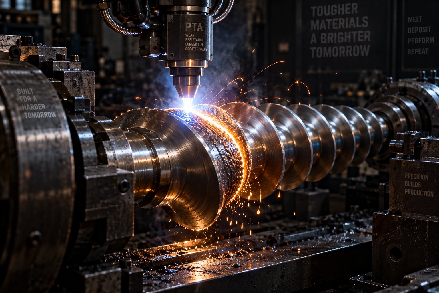
- PTA (Plasma Transferred Arc) surfacing — the gold standard for screw flight rebuilding. A plasma arc melts powdered alloy directly onto the flight tip, creating a true metallurgical fusion bond with the base metal while maintaining minimal penetration into the base material. PTA delivers precise bead control even on narrow flight tips as small as 3-4 mm wide, making it especially suited to screws with fine-pitch or small-diameter geometries.
- MIG and TIG weld overlay — more widely available and suitable for larger flight widths and general rebuilding applications. MIG offers faster deposition rates; TIG provides better control for detail work and thinner deposits. Both create fusion bonds, but typically with higher dilution of the base metal into the overlay, which can reduce the hardfacing's effective hardness.
- Thermal spray processes — including HVOF (high-velocity oxy-fuel) and flame spray. These deposit material at lower temperatures than welding, which reduces heat distortion risk. However, the bond is primarily mechanical rather than metallurgical, making thermal spray coatings more susceptible to peeling under the high compressive and shear loads inside an extruder barrel.
- Chrome plating — used in specific applications where a thin, hard surface layer is sufficient and corrosion resistance is the primary concern. Chrome provides excellent chemical resistance but limited thickness buildup capability, restricting its use to screws with minimal dimensional loss.
The surfacing thickness deposited during the weld overlay typically ranges around 1-2 mm — just enough to restore the flight OD with adequate machining allowance, without adding excessive weight or creating thermal mass that could crack during cooling. In PTA surfacing specifically, the cross-section area of the deposited bead is carefully controlled relative to flight width. Too little material and there's insufficient stock for finish machining. Too much and the molten pool becomes unstable — particularly on small-diameter screws where pool length can exceed the critical threshold, causing liquid metal to drip off the flight.
Automated PTA systems have refined this balance considerably. Modern installations use PLC-controlled torch positioning that accurately tracks the screw flight pitch, adjusting arc current as the torch moves from the deeper flights of the feed zone to the shallower flights of the metering zone. This variable control is essential because flight height directly affects heat dissipation — taller flights in the filling zone absorb heat differently than the shorter flights in the dosing zone, requiring current adjustments along the screw length to maintain consistent bead quality.
Precision Machining and Final Finishing
The buildup phase leaves the screw looking rough — weld beads protrude above the target flight OD, surfaces are uneven, and the precise geometry that makes a plasticating screw function correctly doesn't yet exist. The machining phase is where dimensional accuracy is restored, and it's every bit as critical as the welding that preceded it.
Here's the typical sequence a qualified shop follows after the weld overlay has cooled and been inspected for defects:
- Stress relief (when required) — depending on the alloy system and base metal, a controlled thermal cycle may be performed to relieve residual welding stresses before any cutting begins. This prevents distortion during machining and reduces the risk of delayed cracking.
- Straightness verification — the screw is mounted between centers and runout is re-checked. Welding heat can introduce slight bowing even with proper preheating and fixturing. Any deviation beyond tolerance is corrected at this stage, before material removal begins.
- Flight OD grinding to final diameter — the most critical machining operation. A cylindrical grinder or lathe-mounted grinding attachment removes excess weld material until the flight OD reaches the target diameter — sized, as discussed earlier, to match the actual barrel bore and deliver the correct radial clearance. Every flight pitch along the screw length must achieve this dimension within tight tolerances.
- Root re-machining (if needed) — in cases where the root (channel floor) has experienced erosion, the root diameter is re-cut to restore the original channel depth and compression ratio. This step directly affects melting performance and output consistency.
- Flight edge re-profiling — the leading and trailing edges of each flight are re-ground to the correct radii specified in the OEM drawing. Sharp, square edges — while they might look precise — create material hang-up points where polymer stagnates, degrades, and contaminates the melt stream. Proper radii ensure smooth material flow over the flight lands.
- Surface finishing — the root and flight flanks are polished to the specified surface roughness (Ra value). Smoother surfaces reduce friction, minimize polymer adhesion, and improve the self-cleaning behavior of the screw channel during color or material changes.
- Final dimensional inspection — every measurement taken during the initial receiving inspection is repeated on the finished screw. Flight OD, root depth, flight width, radii, overall length, and concentricity are all verified against the repair specification before the screw is released.
Concentricity deserves special emphasis. If the rebuilt flight OD is not perfectly concentric with the screw's rotational axis, one side of the flight will run tighter against the barrel while the opposite side has excessive clearance. You'll get uneven wear from the first hour of operation — the same adhesive wear pattern that misalignment causes, except this time it's built into the screw itself. Quality shops verify concentricity by rotating the finished screw between centers and measuring TIR at every flight.
Consistent flight depth is equally important. Even small variations in channel depth from one pitch to the next create inconsistent melt behavior — localized pressure spikes, uneven melting, and product quality variation that process adjustments can mask but never fully correct. The machinist must maintain uniform root depth within each screw zone (feed, transition, metering), transitioning smoothly between zones exactly as the original design intended.
Smooth transitions throughout the screw geometry — between zones, between flight flanks and roots, at the start and end of mixing elements — prevent material from hanging up, degrading, and eventually generating black specks or carbonized contamination in your product. A rebuilt screw that looks dimensionally perfect on paper but has sharp internal corners or rough grinding marks in the channel will cause processing headaches that mimic a screw design problem rather than a rebuild quality problem.
The machining phase is where craftsmanship meets engineering. A shop that invests in the right welding alloys but rushes the finish grinding, skips the edge profiling, or doesn't verify concentricity at every flight is delivering an incomplete repair — one that may measure correctly at a few spot-check locations but underperforms across its full operating length. Insisting on complete final inspection documentation, not just a summary sheet, gives you the data to verify that every step was executed to specification.
Dimensional precision, however, only tells part of the story. The long-term durability of the repair — whether it lasts six months or five years — depends heavily on which alloy was deposited and how it was bonded to the base metal. That metallurgical layer sitting on the flight tips is doing all the real work once the screw starts turning.
The Metallurgy Behind Lasting Extruder Screw Hardfacing Alloys
Two screws can go through the exact same rebuild process — identical welding equipment, identical machining tolerances, identical final dimensions on the inspection report — and one lasts four years while the other fails in under six months. The difference isn't in the machining. It's in the metallurgy. The alloy deposited on those flight tips, and the way it bonds to the base metal, determines whether your repair investment pays dividends or evaporates the first time the screw encounters real processing loads.
Understanding extruder screw hardfacing alloys doesn't require a materials science degree. But it does require knowing which alloy families exist, what each one resists best, and why the method of application matters just as much as the material itself.
Hard-Facing Alloys and Their Performance Characteristics
Three major alloy families dominate screw repair work. Each is engineered to excel against a specific wear mechanism — and each carries trade-offs that make it a poor fit for the wrong application.
Cobalt-based alloys — sold under trade names like Stellite — are the toughest option in the lineup. The cobalt matrix is ductile enough to absorb impact without cracking, and it famously maintains its hardness at elevated temperatures. Stellite 6, the most widely specified cobalt grade, delivers excellent resistance to combined wear and corrosion, making it a go-to choice when screw flights see shock loads or thermal cycling alongside moderate abrasion. The trade-off? Pure abrasion resistance is lower than what nickel-based alternatives offer.
Nickel-based alloys — the Colmonoy family being the most recognized — are harder and more abrasion-resistant than cobalt grades. The Ni-Cr-B-Si chemistry forms hard boride and carbide phases that resist the grinding action of fillers. Colmonoy 56, running approximately 50-55 HRC, is the workhorse for standard wear-plus-corrosion duty across most filled compounds. For corrosive environments like PVC processing, nickel's inherent chemical resistance gives it an edge over cobalt — the nickel base provides a natural barrier against acid attack from HCl and other aggressive byproducts. The limitation? Nickel alloys are less ductile, which means they can crack under heavy impact or if handled roughly during screw removal.
Tungsten carbide composites sit at the extreme end of the abrasion-resistance spectrum. These aren't pure alloys but rather a matrix — typically nickel-based — embedded with tungsten carbide particles that are far harder than either the matrix material or any filler particle the screw will encounter. A tungsten carbide screw coating like Colmonoy 83 pushes above 60 HRC at the matrix level, with the embedded WC particles harder still. This is the answer when you're running 30%+ glass-fiber nylon, heavily mineral-filled compounds, or wood-plastic composites that destroy conventional hardfacing in months.
The following comparison table maps each family to its strengths, limitations, and ideal barrel extruder applications:
| Alloy Family | Best For | Wear Resistance | Corrosion Resistance | Typical Applications |
|---|---|---|---|---|
| Cobalt-based (Stellite 6, Stellite 12) | Impact + high-temperature duty; combined moderate wear and corrosion | Moderate — 35-50 HRC range; excellent hot hardness | Good — cobalt matrix resists oxidation and moderate chemical attack | Screws experiencing shock loads, thermal cycling, or mixed-material processing with moderate filler levels |
| Nickel-based (Colmonoy 56) | Standard abrasion + corrosion resistance; the general-purpose default | High — 50-55 HRC; hard boride and carbide phases resist grinding wear | Very good — nickel base provides strong resistance to PVC byproducts and acidic degradation compounds | Most filled compounds, PVC and chemically aggressive resins, general extrusion and injection molding feedscrew rebuilds |
| Tungsten carbide composite (Colmonoy 83, Colmonoy 88) | Extreme abrasion from glass fiber, mineral fillers, and recycled/contaminated feedstock | Very high — 60+ HRC matrix with embedded WC particles far harder than any polymer filler | Moderate — corrosion performance depends on the matrix alloy surrounding the carbide particles | High glass-fiber nylon (30%+), heavily mineral-filled masterbatch, wood-plastic composites, recycled material with contaminants |
One practical caveat worth noting: the hardness values listed above represent typical ranges, not guarantees. As-deposited hardness varies with the application method, the degree of dilution between the overlay and the base steel, and the specific deposition parameters used. Industry specialists advise requesting the achieved hardness on the actual screw rather than relying solely on catalog specifications. A 5 HRC difference from expected values may indicate excessive dilution — meaning too much base metal mixed into the weld pool, diluting the alloy's protective chemistry.
Why Alloy Spray Welding Delivers Superior Bond Strength
Imagine applying a wear-resistant coating to a screw flight the way you'd apply paint to a wall. The coating sits on the surface, held in place by mechanical grip — roughness, texture, physical interlocking. Under normal conditions it stays put. But subject it to the compressive loads, shear forces, and thermal cycling inside an extruder barrel, and that mechanical bond becomes the weak link. The coating peels, flakes, or spalls off the flight, exposing bare base metal to accelerated wear and contaminating your melt stream with hard metallic debris.
This is the fundamental difference between mechanical adhesion and metallurgical bonding — and it's why alloy spray welding extruder screw repair delivers dramatically longer service life than coatings that rely on surface grip alone.
In a true metallurgical bond, the metals in the hardfacing alloy and the metals on the screw surface intermingle at the atomic level. As thermal spray specialists at HTS Coatings describe it, the spray-and-fuse process uses high heat to create a bond where the coating metals and the base materials are "intermingling" — fusing together to create a coating without voids that can withstand more wear over longer periods. This fusion bond behaves like a single integrated material rather than two separate layers stacked on top of each other.
The metallurgical mechanics work like this: during alloy spray welding, the hardfacing material is heated to a molten or near-molten state and deposited onto a preheated screw surface. At the interface, atoms from the base metal diffuse into the alloy layer and vice versa, creating an intermetallic transition zone. This zone anchors the hardfacing to the substrate through atomic-level bonds that are orders of magnitude stronger than any mechanical interlock.
Three critical process variables govern the quality of this bond:
- Heat-affected zone (HAZ) management — the region of base metal directly beneath the weld deposit experiences a thermal cycle that alters its microstructure. Too much heat penetration can soften the base metal or create brittle phases. Too little means the bond interface doesn't fully fuse. Skilled operators control arc energy and travel speed to keep the HAZ narrow and metallurgically sound.
- Dilution control — dilution is the percentage of base metal that melts into the deposited alloy. Some dilution is necessary for a fusion bond, but excessive dilution degrades the overlay's wear-resistant chemistry. PTA (Plasma Transferred Arc) processes excel here because they achieve strong metallurgical bonds with minimal penetration into the substrate — typically just enough to fuse without contaminating the alloy's protective carbide and boride phases.
- Base metal integrity preservation — the goal is to armor the flight surface without compromising the structural properties of the core. This requires in-depth knowledge of the base material composition, its heat treatment history, and any previously applied coatings. Applying the wrong alloy or using incorrect preheat temperatures can trigger cracking, delamination, or distortion that ruins the screw entirely.
This combination of material science and process control is precisely why alloy spray welding demands specialized expertise. Providers like NANHAIYA, for example, offer dedicated alloy spray welding and wear-resistant surface treatments specifically for extruder screws and barrels facing wear, corrosion, and service-life degradation challenges. The value of working with a specialist in this space isn't just access to the right alloys — it's the process knowledge that ensures those alloys are applied with the bond quality, dilution control, and thermal management that determine whether the repair lasts one year or five.
The wear characteristics of spray-and-fuse coatings are directly comparable to those of hardface weld overlays, but the spray process offers an advantage on certain geometries: it can coat complex surfaces more uniformly than a manual weld pass, and the fusing step ensures the entire deposit achieves a consistent metallurgical bond rather than relying on the operator's bead-by-bead consistency. For large-diameter screws and barrels, this combination of uniform coverage and fusion bonding is especially valuable.
Matching Alloy Selection to Wear Mechanism
Here's where the wear taxonomy from earlier in this guide becomes a practical decision tool. You identified the dominant wear mechanism on your screw — adhesive, abrasive, corrosive, or a combination. That diagnosis now maps directly to the alloy family and application method that gives the repair its best chance at long-term survival.
Think of it as a three-question decision sequence that experienced hardfacing engineers follow:
- What is grinding the flight? If steady abrasive filler — glass fiber, mineral particles, recycled contaminants — is doing the damage, you need maximum hardness. Nickel-based Colmonoy 56 is the default. For severe abrasion (30%+ glass-filled compounds, wood-plastic composites), step up to a tungsten carbide composite like Colmonoy 83 or 88, where embedded WC particles outlast any filler particle the screw will encounter.
- Is there impact, shock, or high-temperature cycling? If flights are chipping or cracking rather than wearing smooth, the failure mode is toughness-limited, not hardness-limited. Cobalt-based Stellite earns its premium here. Stellite 6 handles the broadest range of impact-plus-heat scenarios; Stellite 12 adds more tungsten for higher wear resistance while retaining cobalt's ductile advantage.
- What killed the last screw — smooth erosion or chemical attack? Screws worn smooth point toward abrasion-dominant alloys. Screws with pitting, dimpling, or chemical etching patterns demand corrosion-resistant chemistry. For PVC, fluoropolymers, and flame-retardant compounds, nickel-based alloys provide the chemical resistance the application demands. A screw showing both smooth wear and pitting needs a balanced alloy — Colmonoy 56's combination of abrasion and corrosion resistance often fits this dual-threat profile better than either extreme.
For processors running multiple materials through the same equipment, the choice becomes a calculated compromise. A cobalt-based alloy may deliver acceptable — though not optimal — performance across both abrasive and corrosive environments, making it a pragmatic choice for a screw that processes filled polyolefins one week and PVC compounds the next. The alternative is maintaining dedicated screws for each material family, each hardfaced with the optimal alloy for its specific duty. That approach costs more upfront but dramatically extends service life for each screw.
The alloy on your flight tips is your first line of defense against every resin, filler, and contaminant your extruder will process. Choosing it based on price rather than wear mechanism is the single most reliable way to guarantee a short-lived repair.
Getting the metallurgy right — the correct alloy family applied with proper bond quality and dilution control — is what separates a worn extruder screw repair that delivers years of reliable service from one that sends you back to the repair shop before the invoice is even paid. But even the best alloy selection and flawless application mean nothing if the finished screw isn't rigorously verified before it goes back into the barrel. Dimensional precision, runout, surface finish — each must meet specific standards, and the verification process has its own set of requirements that most processors never see.
Post-Repair Quality Assurance: How to Verify a Rebuilt Screw Quality Inspection
A repaired screw that measures correctly at three spot-check locations can still fail catastrophically in production. Why? Because three points don't define a screw — hundreds of interacting dimensions do. Flight OD at every pitch, root depth consistency across each zone, surface finish on every channel wall, and concentricity along the full rotating length all must meet specification simultaneously. Miss any one of these, and the screw produces the same symptoms — surging, melt inconsistency, premature re-wear — that prompted the rebuild in the first place.
This is where rebuilt screw quality inspection separates shops that deliver lasting repairs from those that deliver expensive disappointments. And it's also where you, as the processor receiving the screw, need to know exactly what to verify before reinstallation.
Dimensional Verification Against Specifications
The final inspection should mirror the receiving inspection — same measurements, same locations, same tools — but now comparing finished dimensions against the repair specification rather than the worn baseline. Every measurement the shop recorded when the screw arrived should have a corresponding "after" value on the release documentation.
Here's what a complete dimensional verification includes:
- Flight OD at every pitch along the screw length — not every third or fifth pitch, but every one. A single undersized flight creates a localized leak path that degrades melt seal integrity in that zone. A single oversized flight will drag against the barrel wall, generating adhesive wear from the first revolution.
- Root depth consistency within each zone — feed section channels should all match within tight tolerances, transition section depths should follow a smooth taper, and metering channels should be uniform. Depth variation within a zone disrupts the pressure profile the screw design relies on for consistent melting and conveying.
- Flight width uniformity — poor rebuilding practices can reduce effective flight width during the post-weld grinding process, potentially affecting screw performance and complicating future rebuild potential. Verify that the hardfacing encompasses the full flight width rather than leaving exposed base metal at the edges.
- Flight radii on leading and trailing edges — measured with a radius gauge set and compared to the OEM profile. Radii that are too sharp create polymer hang-up points. Radii that are too generous reduce the effective flight land area and compromise the melt seal.
- Overall length and drive engagement dimensions — shank diameter, keyway dimensions, and drive tang geometry must match the gearbox and thrust bearing assembly precisely. A screw that's dimensionally perfect in the flighted section but 0.005 inches off on the shank will introduce vibration and uneven loading from the moment it starts turning.
Acceptable tolerance ranges vary by screw diameter and OEM specification. As a general principle, flight OD tolerances tighten as screw diameter decreases — a 6-inch screw can tolerate slightly more absolute variation than a 1.5-inch screw while maintaining the same proportional radial clearance. Always request the specific tolerance band your repair shop targeted, and verify that every measurement falls within it — not "most" measurements, not "averages," but every individual reading.
Runout, Straightness, and Surface Finish Standards
Dimensional accuracy means nothing if the screw isn't straight. A flight OD that measures perfectly at every pitch can still run eccentrically if the core shaft has even a slight bow — and eccentricity inside a barrel produces the same uneven wear pattern as misalignment. That's why extruder screw runout tolerance verification is a non-negotiable QA step.
Total indicated runout (TIR) is measured by mounting the finished screw between centers on a lathe or precision rollers, then slowly rotating it while a dial indicator rides along the flight OD and root surfaces. The indicator captures the total radial deviation at each point as the screw completes a full revolution. TIR readings are taken at multiple stations along the screw length — typically every 12 inches or at every zone transition — to build a straightness profile of the entire assembly.
What constitutes an acceptable runout? OEM specifications provide the definitive answer for your specific screw, but general industry practice targets TIR values that ensure the screw rotates concentrically within the barrel bore without creating localized tight spots or excessive clearance zones. Larger-diameter screws tolerate slightly higher absolute TIR because the radial clearance is proportionally larger. Smaller screws — particularly those under 2 inches — require tighter runout control because even minor eccentricity represents a significant percentage of the available clearance.
Surface finish is the third pillar of post-repair verification, and it's the one most often overlooked. The root and flight flanks of the screw channel need to meet specific roughness targets to ensure proper polymer flow. Surface roughness, expressed as an Ra value (average roughness in micro-inches or micrometers), quantifies the small-scale irregularities on the machined surface. A smoother finish (lower Ra) reduces friction between the polymer and the screw surface, minimizes material adhesion during color or resin changes, and reduces degradation-causing hang-up zones where polymer can stagnate and overheat.
Different screw zones may call for different finish targets. Metering zone roots and flanks typically require the smoothest finish because this is where fully molten polymer flows under high pressure — any surface irregularity creates a stagnation point. Feed zone surfaces can tolerate slightly rougher finishes because some surface texture actually aids solids conveying by increasing the friction coefficient between the screw and unmelted pellets. Mixing section geometries — barrier flights, pin mixers, fluted sections — need smooth transitions at every edge to prevent polymer from collecting and degrading in dead spots.
An important nuance: Ra underestimates actual surface height variations because it represents an average value. A surface with an acceptable Ra number could still have isolated deep scratches or grinding marks that create localized hang-up zones. For critical screw zones, asking the repair shop to report both Ra and Rz (mean roughness depth, which approximates the size of the most severe variations) provides a more complete picture of what the polymer will actually encounter.
A structured, multi-disciplinary QA process — where engineering reviews dimensional data, machining verifies runout and finish, and metallurgy confirms hardfacing hardness and bond integrity — catches problems that any single discipline might miss. When evaluating repair providers, ask whether their release process involves cross-functional review or simply a final-inspection technician with a micrometer. The answer tells you a great deal about how seriously they take quality.
What to Expect During Break-In After Reinstallation
You've verified the dimensions, confirmed the runout, and the inspection report looks clean. The screw goes back into the barrel. What happens next? This is the phase — the extruder screw break-in procedure — that virtually every repair provider and most maintenance guides completely ignore. Yet the first hours and days of operation after reinstallation are when subtle problems reveal themselves, and when a little patience prevents a lot of damage.
A freshly rebuilt screw has microscopic surface peaks on even the best-finished hardfacing. These high spots need to wear in against the barrel bore gradually rather than being forced into aggressive contact under full production loads. Think of it the way an engine builder treats a new set of piston rings — controlled loading, progressive ramp-up, and close monitoring.
A practical break-in protocol looks like this:
- Start at reduced RPM — run the screw at 50-60% of normal operating speed for the first several hours. This limits the mechanical loading on the new hardfacing and allows the flight OD to seat against the barrel bore gently, burnishing away micro-peaks without generating the heat or pressure that could cause hardfacing damage.
- Monitor motor current and drive torque closely — establish a new baseline during the first shift. Current draw should be stable and consistent with what you'd expect for the material and speed. Erratic torque spikes can indicate a tight spot where the flight OD is contacting the barrel — a sign of either a runout issue that wasn't caught during QA or a barrel bore irregularity.
- Watch melt temperature and die pressure — compare these readings against historical data from when the screw was last performing well (ideally from your baseline records). A rebuilt screw should produce melt temperatures at or slightly below previous readings at the same RPM, since restored clearances reduce shear heating. If melt temperature is higher than expected, something is wrong — possibly excessive interference fit, misalignment, or a barrel zone that wasn't performing as assumed.
- Track output rate versus RPM — this is your most direct measure of pumping efficiency. A properly rebuilt screw with correct barrel clearance should deliver the same or better output per revolution compared to the worn screw it replaced. Declining output per revolution during break-in is a red flag that demands investigation before proceeding to full production speed.
- Inspect the first extrudate or molded parts carefully — look for black specks (contamination from the rebuild process or from material trapped behind previously worn areas), color inconsistency (indicating incomplete mixing), and dimensional variation (reflecting pressure instability). A small number of specks during the first few minutes of operation is normal as residual purge material clears. Persistent contamination after the first 15-20 minutes warrants a shutdown and screw pull to investigate.
After the initial break-in period, gradually ramp up to full production speed over the next one to two shifts. Continue monitoring the same parameters — motor load, melt temperature, die pressure, and output rate — and compare them against the targets you established during diagnosis. If the rebuilt screw is performing to specification, document these new baseline values. They become your reference point for tracking wear on the rebuilt screw going forward, completing the diagnostic loop that started with the inspection protocol described earlier in this guide.
Warning signs that something may not be right during or after break-in include:
- Motor current steadily climbing over the first few days of production — suggests progressive interference or a developing alignment issue
- Melt temperature creeping above target despite stable RPM and barrel heater settings — may indicate the barrel bore condition was worse than the measurements suggested, or that the screw OD was built slightly oversize
- Persistent black specks or degraded material in the product — could point to rough surface finish in the screw channels, a hang-up zone created by a sharp edge or grinding mark, or polymer trapped in a crevice at the boundary between new hardfacing and original base metal
- Output rate declining from initial post-repair levels — if performance drops within the first weeks, the new hardfacing may already be wearing, indicating either the wrong alloy selection for the dominant wear mechanism or a bond quality issue that's allowing premature material loss
Any of these patterns warrants pulling the screw for re-inspection rather than running through the problem. A quick verification measurement within the first month of service can catch a developing issue before it becomes a costly repeat failure — and before the barrel suffers the collateral damage that turns a screw problem into a system problem.
Of course, the ultimate goal isn't just a successful repair and break-in. It's making sure the rebuilt screw stays in service as long as possible before the next intervention. That means shifting from reactive maintenance to a structured prevention strategy — one that protects your repair investment through disciplined monitoring and operational best practices.
Preventive Maintenance to Protect Your Extruder Screw Repair Investment
A rebuilt screw that performs flawlessly on day one can wear right back to its pre-repair condition in half the expected service life — if the operational environment that caused the original wear goes unchanged. The hardfacing alloy doesn't care that you spent weeks getting the repair right. It responds to the same physics, the same abrasive fillers, the same misalignment forces, and the same thermal abuse that destroyed the original surface. The only variable you actually control is how aggressively you monitor, maintain, and protect the equipment after reinstallation.
This is where the economics of worn extruder screw repair either pay off or collapse. A disciplined extruder screw preventive maintenance program can double or triple the interval between rebuilds. Neglect turns a $5,000 repair into a recurring annual expense — with compounding barrel damage thrown in for free.
Scheduled Inspection Intervals and Monitoring Protocols
The goal isn't to pull screws constantly — that's expensive and disruptive. The goal is to pull them at exactly the right time: late enough to extract maximum service life, early enough to avoid the cascading damage that turns a rebuildable screw into scrap. Achieving that balance requires two complementary approaches: periodic physical inspection and continuous process monitoring.
A structured screw and barrel inspection schedule looks different depending on what you're processing. Reiloy USA's preventive maintenance guidelines recommend inspecting every six months when running mostly reinforced or filled resins, and annually when processing unfilled materials — continuing at those intervals until wear trends are established for each specific screw, barrel, and resin combination. Once you've documented how fast your equipment wears under your conditions, you can fine-tune the schedule to match your actual wear rate rather than a generic recommendation.
Here's a recommended preventive maintenance schedule framework that balances thoroughness with practical plant constraints:
- Daily — monitor process indicators from the control panel. Track output rate at constant RPM, motor current and torque, melt temperature versus setpoint, and die pressure stability. Record these values in a log or digital system. As MachineCDN's predictive maintenance research emphasizes, a single barrel zone temperature is just a data point — the relationship between all zones over time is predictive intelligence.
- Monthly — review trend data for deviation from baseline. Compare current month's averages against the post-repair baseline you established during break-in. Look for gradual drift: output declining 2-3% per month, melt temperature creeping upward, motor load shifting. These incremental changes are easy to miss day-to-day but unmistakable on a monthly trend chart.
- Quarterly — evaluate product quality metrics against wear indicators. Correlate scrap rate trends, dimensional consistency, and surface quality data with the process parameter trends you've been tracking. A simultaneous uptick in scrap and melt temperature deviation is a strong signal that clearances are opening up.
- Semi-annually (filled resins) or annually (unfilled resins) — pull the screw and measure. Perform a full dimensional inspection: flight OD at every pitch, root depths, flight widths, and straightness. Compare against the post-repair measurements from the rebuild documentation. Calculate the wear rate — inches of OD loss per thousand operating hours — and use that rate to project the next service window.
- At every screw pull — inspect the barrel bore. Measure extruder barrel ID at multiple points and compare to previous readings. Track barrel wear rate alongside screw wear rate. If the barrel is degrading faster than expected, investigate alignment, metallurgical compatibility, and whether the screw's hardfacing alloy is compatible with the barrel liner.
The power of this framework isn't any single measurement — it's the trend. Glycon Corp.'s Jeff Kuhman describes this as identifying the "point of diminishing returns" — the moment where machine adjustments can no longer compensate for wear without measurably impacting production. If you can predict when that point arrives, you can have replacement or rebuild parts ready, schedule installation during planned downtime, and avoid the emergency scramble that costs far more than the parts themselves.
For plants with multiple extrusion lines, IIoT-connected monitoring platforms can automate much of this tracking by continuously capturing barrel zone temperatures, melt pressures, motor loads, and die pressures — then flagging deviations before they become failures. Even legacy extrusion lines with older PLCs can be connected to modern monitoring systems without modifying existing controls, turning data that was always being generated into actionable maintenance intelligence.
Operational Practices That Extend Screw and Barrel Life
Monitoring tells you when wear is happening. Operational discipline determines how fast it happens. Several everyday practices have an outsized impact on how long your rebuilt extruder screws and extrusion barrels last — and most of them cost nothing to implement.
Purging procedures matter more than most processors realize. Reiloy USA recommends always removing corrosive and filled resins before idling equipment. Leaving PVC or glass-filled compounds sitting in a hot barrel during shutdown allows corrosive byproducts to attack metal surfaces and abrasive particles to settle against flight lands under static conditions. A quality commercial purging compound (CPC) displaces these aggressive materials, seals the system against oxidation during shutdown, and dramatically reduces carbon buildup that would otherwise require manual screw pulls to clean. Some CPCs are specifically formulated to cool and shrink, pulling built-up material and carbon away from metal surfaces — a routine that prevents the gradual accumulation that degrades performance between inspections.
Controlled startup and shutdown sequences minimize thermal shock. Rapid heating of a cold barrel or rapid cooling of a hot one creates thermal gradients that stress both the barrel liner and the screw's hardfacing. Over hundreds of cycles, these stresses can initiate micro-cracks in the hardfacing layer — cracks that propagate under operating loads until the coating delaminates. A gradual heat-up sequence, allowing each barrel zone to reach setpoint and stabilize before introducing screw rotation and material, protects both components.
Screw speed and back pressure settings directly affect wear rate. Running at maximum RPM to squeeze out extra throughput increases the contact pressure and relative velocity between flight OD and barrel wall — the two variables that drive both adhesive and abrasive wear. As components wear, operators tend to incrementally increase screw speed, raise backpressure, and adjust barrel temperatures to compensate. These adjustments use more energy and accelerate wear further — a feedback loop that shortens component life with every twist of the dial. Resist the urge to compensate indefinitely. When process adjustments accumulate beyond your documented threshold, it's time to inspect, not adjust further.
Feedstock quality control is your first line of defense against tramp metal and contamination. Everything from screwdrivers to grinder blades to nuts and bolts find their way into hoppers on plastics machinery. A single piece of tramp metal can gouge a flight, damage the barrel bore, and turn a perfectly good rebuild into an emergency repair. Magnetic separators in the feed throat, metal detectors on conveying lines, and visual inspection protocols for regrind and recycled material are inexpensive safeguards that protect expensive components. Similarly, controlling moisture levels, avoiding cross-contamination between resin types, and screening out oversized or agglomerated pellets reduce the mechanical stresses that accelerate wear in the feed and transition zones.
Alignment verification belongs in every maintenance protocol. Glycon Corp. has been aligning plastics processing machines for over 20 years and reports that very few machines did not require alignment when checked. A misaligned barrel-to-gearbox connection forces the screw to deflect with every rotation, creating the adhesive wear patterns that destroy hardfacing fastest. Checking alignment whenever a screw or barrel is changed — or at minimum annually — is one of the highest-ROI maintenance activities available.
Partnering With a Repair Specialist for Long-Term Service Life
In-house monitoring and disciplined operational practices handle the day-to-day protection. But the metallurgical decisions — which alloy to specify for your next rebuild, whether your barrel liner is compatible with the screw's hardfacing, how to address a combined wear pattern that changed after you switched resin suppliers — require specialized expertise that most processing plants don't maintain internally.
This is where an ongoing relationship with a repair specialist pays for itself many times over. Rather than scrambling to find a vendor after a screw fails, a proactive partnership means your repair provider already understands your equipment, your materials, your wear history, and your production priorities. They can recommend alloy upgrades before problems develop, flag barrel conditions during routine screw rebuilds, and help you optimize your screw and barrel inspection schedule based on actual wear data from your specific operation.
Providers like NANHAIYA, which supports extrusion and injection molding operators with alloy spray welding and wear-resistant surface treatment options for screw wear, barrel wear, and corrosion challenges, exemplify the kind of specialist partnership that shifts maintenance from reactive crisis management to planned lifecycle optimization. Having a provider who understands the metallurgy behind your hardfacing, the processing demands of your resin portfolio, and the wear patterns specific to your equipment transforms screw maintenance from a recurring emergency into a predictable, budgetable line item.
The financial case is straightforward. As Reiloy USA's preventive maintenance handbook emphasizes, a PM program that tracks component wear life helps explain variations in process over time — and as components wear, changes will appear in cycle times, scrap rates, energy consumption, and downtime. A strong PM program minimizes each of these. The alternative — running to failure and reacting to emergencies — costs more in every measurable dimension: parts, labor, lost production, scrap, energy, and customer confidence.
The most cost-effective screw maintenance program combines diligent in-house monitoring with a trusted repair partner who understands your metallurgy, your materials, and your production demands.
Every section of this guide — from diagnosis through root cause analysis, system evaluation, repair method selection, process walkthrough, quality verification, and now prevention — connects to the same core principle: worn extruder screw repair succeeds when it's treated as an engineering discipline, not a one-time transaction. The processors who get the longest life from their extruder barrels and screws are the ones who measure before they act, choose alloys based on wear mechanisms rather than price, verify quality before reinstallation, and protect their investment with the kind of operational discipline and specialist partnerships that keep the repair cycle as long and infrequent as possible. That's not just good maintenance. It's a competitive advantage.
Frequently Asked Questions About Worn Extruder Screw Repair
1. How do I know when my extruder screw needs repair or replacement?
Several measurable indicators signal a worn screw. Track flight OD clearance against barrel ID using a bar micrometer — when radial clearance widens beyond OEM tolerance, pumping efficiency drops significantly. Process-level warning signs include declining throughput at constant RPM, melt temperatures exceeding setpoints despite zero heater output, dropping motor torque, and erratic die pressure fluctuations. If two or more of these indicators appear simultaneously, pull the screw for a full dimensional inspection and compare readings against your baseline documentation to determine severity.
2. What is the cost difference between repairing and replacing an extruder screw?
Extruder screw repair typically costs 25-40% of a new screw purchase price, making it financially compelling when the base metal is in sound condition. However, cost alone should not drive the decision. Key variables include the extent of wear (localized vs. full-length), number of prior rebuilds (industry best practice limits rebuilds to three), base metal integrity, lead time urgency, and whether the original screw design still suits your current processing needs. When repair estimates exceed 60% of new screw cost — especially if extensive straightening, full-length hardfacing, and root re-machining are needed — replacement usually offers better long-term value.
3. What causes extruder screw wear and how does it affect production?
Three primary mechanisms cause screw wear: adhesive wear from metal-to-metal contact due to misalignment or wedging, abrasive wear from glass fibers, mineral fillers, and contaminated feedstock grinding against flight surfaces, and corrosive wear from chemically aggressive materials like PVC releasing hydrochloric acid. These mechanisms often overlap — misalignment combined with filled resins creates simultaneous adhesive and abrasive damage. Production impacts include throughput losses of up to 55% from as little as 0.030 inches of radial wear, rising energy consumption from compensatory RPM increases, inconsistent melt quality, and accelerated barrel degradation.
4. What hardfacing alloys are best for extruder screw repair?
The optimal alloy depends on your dominant wear mechanism. Cobalt-based alloys like Stellite 6 excel against impact and thermal cycling with moderate abrasion resistance. Nickel-based alloys such as Colmonoy 56 (50-55 HRC) offer strong combined abrasion and corrosion resistance, making them the general-purpose default for filled compounds and PVC processing. Tungsten carbide composites like Colmonoy 83 (60+ HRC) deliver extreme abrasion resistance for highly glass-filled or mineral-filled resins. Specialized providers like NANHAIYA offer alloy spray welding services that ensure proper metallurgical bonding and dilution control, which are critical to long-term repair durability.
5. Should I inspect the barrel when repairing an extruder screw?
Absolutely — evaluating the screw without inspecting the barrel is the most common and costly mistake in extruder maintenance. The screw flight OD and barrel bore ID form a precision clearance system, and repairing one while the other remains worn simply recreates oversized clearances from the barrel side. Measure the barrel bore at multiple points using a bore gauge to detect overall enlargement, taper, and ovality. Always send current barrel bore measurements to your repair shop so the rebuilt screw's flight OD can be sized to match the actual barrel condition, ensuring proper radial clearance and maximum service life after reinstallation.
Written by
Nanhaiya Technical Team
Zhoushan Nanhaiya Plastic Machinery Co., Ltd.
The Nanhaiya technical team supports screw and barrel manufacturing projects through application review, technical communication, custom manufacturing coordination, and production and quality control.
Discuss Your Application
Related Articles
More insights on screw barrel technology and plastics processing.

What Nobody Tells You About Screw Barrel For Plastic Machine Design
Oct 10, 2026
Learn how screw barrel for plastic machine design affects melt quality, throughput, and wear life. Covers geometry, resin matching, troubleshooting, and sourcing.
Read Article
Single Screw Extruder for Sheet: Stop Guessing, Start Specifying
Oct 9, 2026
Learn how to specify a single screw extruder for sheet production. Covers screw geometry, resin-specific processing, troubleshooting, and maintenance best practices.
Read Article
PE Pipe Extruder Machine: What Datasheets Won't Tell You
Oct 9, 2026
Learn how a PE pipe extruder machine works, key specs explained, material grade selection, maintenance tips, and buyer guidance beyond the datasheet.
Read ArticleLooking for something else?
Search by material, symptom or product and jump straight to the relevant page.
These are navigation suggestions based on keyword matching — not a quotation, not a delivery commitment, and not a substitute for engineering review. Final specification is confirmed by our engineers against your drawings and processed material.
Need help with screw barrel selection?
Share your machine model, processed material and application. Our team can help with pricing and technical support.