

What Is a Twin Screw Extruder and Why Its Working Principle Matters
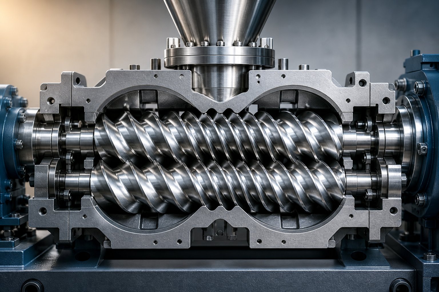
Imagine two helical screws meshing together like precision gears, rotating side by side inside a barrel shaped like a figure eight. That image captures the essence of every twin screw extruder in operation today, whether it is compounding engineering plastics at 2,000 kg/hr or dispersing active pharmaceutical ingredients at lab scale.
A twin screw extruder is a processing machine in which two intermeshing Archimedean screws rotate within a figure-eight-shaped barrel bore to convey, melt, mix, and pressurize materials in a single continuous operation. Its working principle relies on the controlled interaction between screw geometry, barrel thermal management, and material rheology to transform raw feedstock into a homogeneous output.
This article takes a first-principles approach to that working principle. It is written for engineers, process technicians, and students who need more than a bullet-point feature list. You will find a zone-by-zone breakdown of the material journey, the logic behind screw element sequencing, critical geometry parameters, and barrel design considerations that most manufacturer pages never address.
Defining the Twin Screw Extruder
At its core, a twin-screw extruder positions two screws inside a barrel whose internal cross-section consists of two overlapping cylindrical bores. This overlap region, the intermesh zone, is where the real processing magic happens. As the twin screw flights of one rotor sweep through the channel of the other, material is forced along a complex path that combines forward conveyance with intensive transverse mixing. The degree of intermeshing, the direction of rotation, and the specific elements mounted on each shaft all determine how aggressively the machine shears, heats, and homogenizes the feed.
This geometry sets a twin screw extruder apart from single-screw machines, which rely almost entirely on frictional drag against the barrel wall to move material forward. The intermeshing design introduces positive displacement characteristics, self-wiping surfaces, and independently controllable energy input, three pillars that support every processing function downstream.
Why the Working Principle Matters for Process Engineers
Every operational decision you make on a twin screw extruder traces directly back to these foundational mechanics. Adjusting screw speed changes shear energy input. Modifying the feed rate shifts the degree of fill and residence time. Rearranging kneading blocks alters the balance between dispersive and distributive mixing. Setting barrel zone temperatures influences whether energy enters the polymer through mechanical work or conducted heat.
Without a clear mental model of the working principle, these adjustments become trial-and-error guesses. With one, they become predictable engineering decisions that govern product quality, throughput capacity, and energy efficiency. That distinction matters whether you are troubleshooting a degradation issue on the production floor or specifying a new line for a challenging formulation.
The mechanics behind these decisions begin with three foundational conveying and energy-input mechanisms that separate twin screw extrusion from every other melt-processing technology.
The Core Conveying Mechanism and Energy Input Principles
Most descriptions of twin screw extrusion stop at "the screws rotate and mix material." That tells you what happens but not why it happens, or why this machine behaves so differently from a single-screw extruder running the same polymer. Three foundational mechanisms explain the difference: positive displacement conveying, self-wiping action, and starve-fed operation. Each one traces back to the intermeshing geometry, and together they give process engineers a level of control that no other continuous melt-processing platform can match.
Positive Displacement and the Intermeshing Geometry
Picture the channel between two adjacent flights on one screw. In a single-screw extruder, that channel is open on one side, so material only moves forward when frictional drag against the barrel wall exceeds the resistance from downstream pressure. Change the back pressure, and the output changes with it.
In a co rotating twin screw extruder, the flight tip of the neighboring screw enters that channel, effectively closing it off into an enclosed, C-shaped chamber. As the twin screws rotate, each chamber advances axially along the barrel, carrying a fixed volume of material with it. This is positive displacement conveying: the material moves forward because it is physically trapped and pushed, not because friction happens to win a tug-of-war with back pressure.
The practical consequence is significant. Output becomes far less sensitive to changes in die restriction or melt viscosity. Whether you are processing a low-viscosity liquid additive or a high-viscosity engineering resin, the intermeshing flights maintain volumetric consistency. This is why twin screw extrusion delivers tighter weight tolerances and more predictable throughput than drag-flow-dependent alternatives, especially when formulations change frequently on the same line.
The degree of intermeshing determines how "sealed" each C-shaped pocket really is. A tighter intermesh gap improves the positive displacement effect and increases pressure-generating capability, but it also raises local shear stress. Engineers balance this gap based on whether the application demands aggressive dispersion or gentle handling of heat-sensitive materials.
Self-Wiping Action and Residence Time Control
Positive displacement explains how material moves forward. Self-wiping explains why it does not stay behind and degrade.
In a co-rotating configuration, both screws turn in the same direction. As they rotate, the flight flank of one screw sweeps across the root (channel floor) of the other screw, scraping material off the metal surface with every revolution. No stagnant layer is allowed to accumulate, overheat, or decompose. The barrel wall is similarly wiped by the flight tips, creating a continuously renewed melt film that maximizes heat transfer efficiency.
This kinematic wiping has a direct consequence for residence time distribution (RTD). Because material cannot hide in dead zones, virtually all particles travel through the barrel in roughly the same amount of time. The result is a narrow RTD, close to plug-flow behavior. For reactive screw extrusion processes, such as grafting or peroxide-initiated crosslinking, a narrow RTD is essential. If some material stays too long it over-reacts; if it exits too soon it under-reacts. The self-wiping geometry prevents both extremes.
Heat-sensitive polymers benefit equally. Materials like PVC, PET, or bioplastics that degrade rapidly above a threshold temperature need short, uniform exposure to shear heating. By eliminating stagnant pockets where material could sit and cook, the self-wiping action keeps thermal history consistent across every pellet exiting the die.
Starve Feeding vs Flood Feeding
Here is a distinction that separates competent twin screw operation from guesswork: the difference between starve feeding and flood feeding, and why it matters for energy control.
A single-screw extruder typically operates flood-fed. The hopper sits directly over the feed throat, gravity fills the screw channel completely, and the screw speed alone determines both output rate and shear energy input. Speed and throughput are locked together. Want more output? Turn the screw faster, but accept the higher shear that comes with it.
Twin screw extruders, particularly the High Speed Energy Input (HSEI) type that dominates compounding, break this coupling. They operate starve-fed: a gravimetric feeder meters material into the barrel at a precisely controlled rate independent of screw speed. The screw channels in the feed zone are only partially filled, and the feed rate, not the screw rpm, sets the throughput.
Why does this matter? Because it gives operators two independent control levers instead of one:
- Feed rate controls throughput (kg/hr) and, by extension, how full the screw channels are.
- Screw speed controls the shear energy applied to each kilogram of material passing through the machine.
This decoupling is the foundation of specific mechanical energy (SME) management. SME, expressed in kW per kg/hr, quantifies how much motor-driven energy each unit of material absorbs. As PlasticsToday detailed in its HSEI coverage, the applied power can be calculated from motor rating, percent torque, running rpm versus maximum rpm, and gearbox efficiency. Dividing that applied power by the feed rate yields SME, a single number that captures the mechanical intensity of the process.
Imagine you are compounding a carbon-black masterbatch that needs aggressive dispersion. You can increase screw speed to raise shear without changing the feed rate, boosting SME to break down agglomerates. Conversely, for a shear-sensitive bio-resin, you can reduce screw speed while maintaining output, lowering SME to protect molecular weight. Flood-fed systems simply cannot offer this flexibility.
Starve feeding also enables downstream side stuffing. Because the pressure gradient through much of the barrel is essentially zero in a starve-fed process, secondary feeders can introduce fillers, fibers, or additives directly into the melt stream at mid-barrel positions without fighting back pressure. This capability is critical for high-filler-loading compounds and for preserving fiber length in glass-reinforced formulations.
Together, positive displacement, self-wiping, and starve-fed operation form the mechanical foundation upon which every screw configuration, barrel layout, and process recipe is built. The next logical question is how these principles express themselves differently depending on whether the twin screws co-rotate, counter-rotate, or are replaced by a single screw entirely.
Co-Rotating vs Counter-Rotating vs Single Screw Extruders
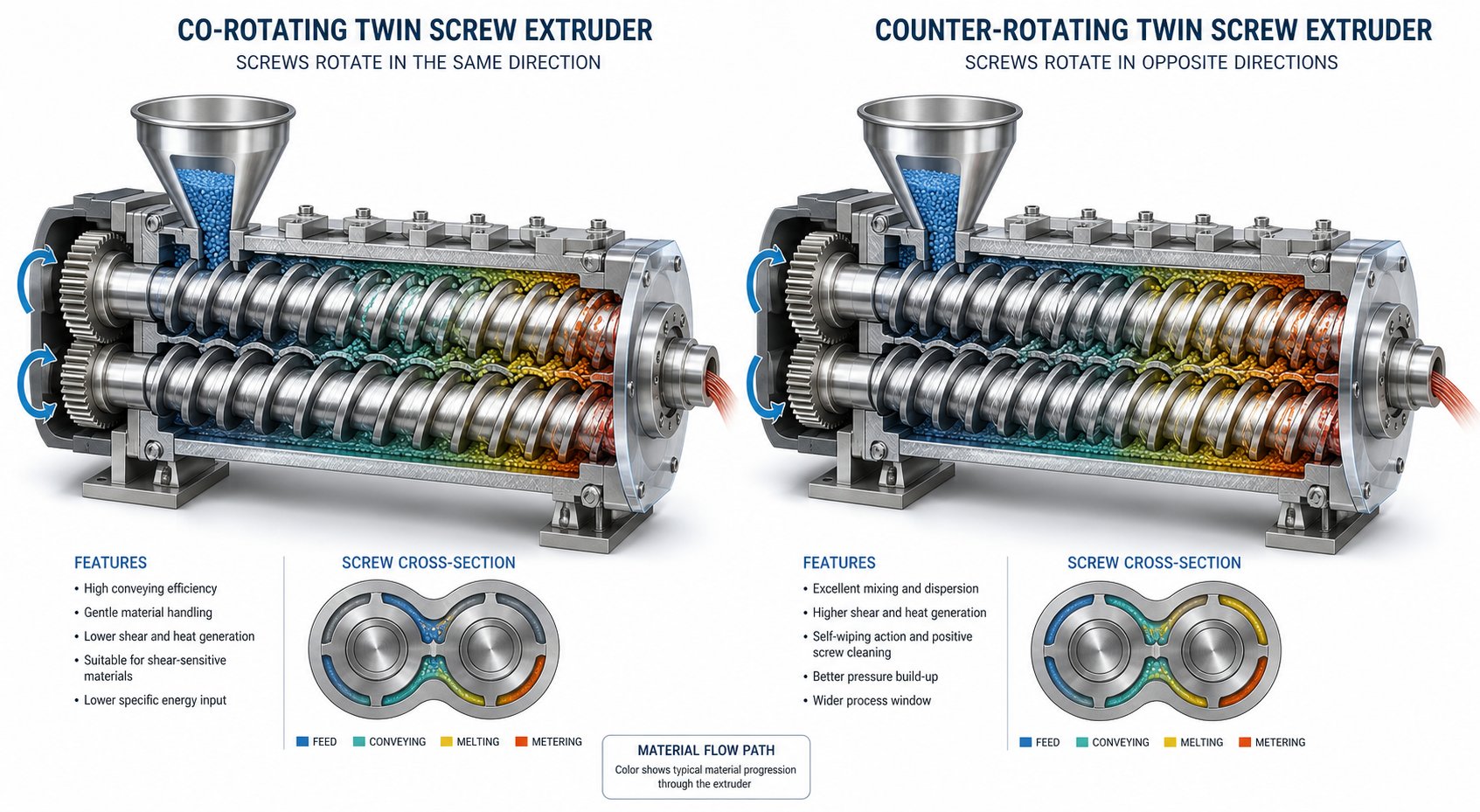
The direction two screws rotate relative to each other is not a minor engineering detail. It fundamentally reshapes the flow field, the shear profile, and the range of applications the machine can serve. Understanding co rotating and counter rotating twin screw extruder configurations, alongside single-screw alternatives, gives you a practical framework for matching machine type to processing goal.
How Co-Rotating Screws Achieve Superior Mixing
In a co-rotating parallel twin screw extruder, both screws turn in the same direction, typically with a fully intermeshing geometry. Material follows a figure-eight path as it transfers from one screw to the other at the intermesh zone. Each time material crosses that zone, it experiences a dramatic change in flow direction and velocity, producing intense distributive mixing without requiring extreme screw speeds.
This figure-eight transfer is what makes co-rotating designs so effective at dispersing fillers, breaking down agglomerates, and homogenizing polymer blends. Intense shear fields develop both between the screws and between each screw and the barrel wall, while kneading blocks add an elongational flow component that Technovel notes imposes a complex deformation history on the material. Critically, the self-wiping action described earlier prevents localized overheating, which means engineers can push screw speeds higher, often above 600 rpm, without creating degradation pockets. That combination of high speed tolerance and thorough mixing is why co-rotating machines dominate compounding, reactive extrusion, and masterbatch production.
Screw element combinations can also be designed freely on co-rotating platforms, letting engineers control exactly where and how much energy enters the material along the barrel length. This modular flexibility simply does not exist on most counter-rotating or single-screw systems.
Counter-Rotating and Conical Twin Screw Configurations
Flip one screw's rotation direction and the processing character changes dramatically. In a counter-rotating double screw extruder, the screws turn in opposite directions, drawing material into the intermesh region and compressing it between the two shafts. This creates a calendering effect, similar to what happens when material passes through a pair of calender rolls.
The calendering nip generates high localized pressure under relatively gentle shear conditions. Material undergoes repeated compressive and elongational deformation rather than the intense shearing typical of co-rotating designs. As extrusion specialists have documented, this makes counter-rotating machines well suited to thermally sensitive materials like rigid PVC, where high shear would trigger decomposition.
However, that same calendering action produces a lateral separation force on the screws, which can cause bending and accelerated barrel wear at high rpm. This structural constraint limits practical operating speeds and, consequently, throughput capacity compared to co-rotating alternatives.
The conical twin screw extruder represents a specialized evolution of counter-rotating geometry. Instead of parallel shafts, the screws taper from a large feed-end diameter to a smaller discharge diameter. This design offers two advantages: the wide feed section accommodates bulky, low-bulk-density powders, while the narrowing geometry progressively reduces shear as the material melts and becomes more heat-sensitive downstream. Conical configurations are a standard choice for PVC pipe, sheet, and profile extrusion lines where steady pressure buildup and gentle melt handling take priority over mixing intensity.
Comparison Table: Co-Rotating, Counter-Rotating, and Single Screw Extruder Types
The table below consolidates the key performance parameters that engineers evaluate when selecting a screw extruder type for a specific application. Use it as a quick reference for initial machine selection before diving into detailed screw and barrel design.
| Parameter | Co-Rotating Twin Screw | Counter-Rotating Twin Screw | Single Screw |
|---|---|---|---|
| Mixing Capability | Excellent (distributive and dispersive) | Moderate (primarily dispersive via calendering) | Limited (relies on special mixing sections) |
| Self-Wiping Ability | Full self-wiping | Partial (limited by counter-rotation geometry) | None |
| Pressure Generation | Moderate (often needs gear pump for high-pressure dies) | High (calendering nip builds pressure efficiently) | High (continuous drag-flow compression) |
| Maximum Screw Speed | High (600 - 1,200+ rpm) | Low to moderate (typically < 150 rpm) | Moderate (60 - 150 rpm) |
| Typical L/D Ratio | 32:1 to 52:1 | 16:1 to 28:1 (parallel); 14:1 to 22:1 (conical) | 24:1 to 36:1 |
| Throughput Characteristics | Starve-fed; throughput decoupled from screw speed | Flood-fed; high fill, speed-dependent output | Flood-fed; output tied directly to screw speed |
| Residence Time Distribution | Narrow (near plug-flow) | Narrow to moderate | Broad |
| Primary Applications | Compounding, masterbatch, reactive extrusion, devolatilization | PVC pipe and profile extrusion, sheet forming | Film, pipe, profile, and sheet extrusion of single-resin formulations |
A few patterns stand out. Co-rotating machines excel wherever mixing intensity and formulation flexibility are the priority. Counter-rotating and conical configurations earn their place when a thermally sensitive material like rigid PVC demands low-shear, high-pressure forming. Single-screw extruders remain the cost-effective workhorse for straightforward extrusion of single-polymer products where complex compounding is unnecessary.
Of course, selecting the right machine type is only the starting point. The real processing detail lives inside the barrel, where material passes through distinct functional zones, each engineered to accomplish a specific transformation. That zone-by-zone journey reveals how the principles discussed so far translate into physical and thermal changes at every stage of the process.
The Complete Material Journey from Feed Hopper to Die Exit
A polymer pellet entering the feed throat of a twin screw extruder machine undergoes a dramatic transformation. Over a span of seconds, it will be conveyed, compressed, melted, sheared into a homogeneous fluid, stripped of volatiles, and pressurized through a die. Each stage happens inside a specific functional zone, and each zone exists because the material's physical state demands a different type of mechanical and thermal action.
The twin screw extrusion process can be broken down into five sequential zones. While exact barrel positions vary with screw configuration and application, the functional sequence remains consistent across virtually every co-rotating extruder twin screw platform:
- Feeding and solid conveying zone — intake and forward transport of raw solids
- Melting and plasticizing zone — conversion of solids into a viscous melt
- Mixing and kneading zone — dispersive and distributive homogenization
- Venting and degassing zone — removal of moisture, air, and volatiles
- Metering and pumping zone — pressure buildup for stable die flow
Feeding and Solid Conveying Zone
The journey begins when a gravimetric feeder meters raw material, typically pellets, powder, or granules, into the barrel's feed opening at a controlled rate. Inside, deep-flighted conveying elements with a large pitch grab the loosely packed solids and push them forward. You'll notice that at this stage the screw channels are only partially filled, a hallmark of starve-fed operation that keeps throughput and screw speed independent.
Barrel temperature in this zone is often set low, sometimes even water-cooled. Why? Premature melting creates a sticky film on the screw surface that acts like a lubricant, reducing the friction needed to convey solids forward. In severe cases, molten material bridges across the feed opening and blocks incoming material entirely. Keeping the feed zone cool preserves solid-state friction and ensures reliable transport into downstream zones.
The material here is still a loose bed of discrete particles. Bulk density is low, interparticle air is abundant, and no significant pressure has built up yet. That changes rapidly once the solids encounter their first kneading block.
Melting and Plasticizing Zone
This is the most energy-intensive stage of the entire process. As material advances into a section populated by kneading blocks, the screw geometry shifts from open conveying channels to staggered disc elements that force the polymer through narrow clearances. The result is intense shear deformation.
Shear converts mechanical energy into heat directly within the material, a process known as viscous dissipation. Simultaneously, barrel heaters conduct thermal energy inward. Under this dual assault, solid pellets soften at their surfaces, deform, and gradually coalesce into a continuous viscous melt. The transition is not instantaneous; you can imagine a moving front where solid cores persist within an increasingly dominant melt phase until the last unmolten fragment is consumed.
Polymer rheology plays a decisive role here. Most thermoplastic melts are shear-thinning, meaning their apparent viscosity drops as shear rate increases. This property is actually beneficial during melting: as the kneading blocks impose high shear, the softening polymer flows more readily, improving heat transfer and accelerating the melting process. Temperature-dependent viscosity reduction further assists, creating a positive feedback loop where rising temperature and rising shear rate both drive viscosity down, allowing progressively easier processing.
Engineers control the aggressiveness of this zone by selecting kneading block stagger angles. A 60-degree forward stagger provides strong shear with moderate forward conveying, while a 90-degree configuration, often called neutral kneading blocks, maximizes shear intensity by eliminating any forward-pumping component.
Mixing, Venting, and Metering Zones
With the polymer fully molten, the process shifts from phase transformation to refinement. In the mixing and kneading zone, additional kneading blocks and specialized mixing elements, such as gear-type or turbine-style distributive mixers, work to break down filler agglomerates (dispersive mixing) and spread all components uniformly throughout the melt (distributive mixing). This is where a masterbatch achieves its color consistency, where glass fibers get wetted by the matrix, and where nano-additives reach their target dispersion state. The distinction matters: dispersive mixing requires high stress to fracture cohesive clusters, while distributive mixing requires repeated reorientation and splitting of flow streams to achieve spatial uniformity.
The venting and degassing zone follows a fundamentally different design philosophy. Here, the screw configuration switches back to deep-flighted, large-pitch conveying elements that transport material quickly, reducing fill level and local pressure. This creates a partially filled barrel section where the melt surface is exposed rather than pressurized. Vacuum ports positioned at these low-pressure zones draw out trapped air, moisture, and volatile byproducts. A melt seal, typically formed by reverse-pitch elements just upstream of the vent, prevents vacuum from pulling material backward and ensures the pressure drop is localized exactly where it is needed.
Effective degassing is essential for product quality. Residual moisture in hygroscopic polymers like nylon or PET causes hydrolytic chain scission that destroys mechanical properties. Trapped volatiles produce bubbles, surface defects, and odor in the final product. In recycling operations, where contaminated and variable-quality feedstock is common, venting zones do especially heavy lifting. Twin screw extruders used as part of a screw extruder granulator line rely on this degassing capability to produce clean, bubble-free pellets from post-consumer waste streams.
Finally, the metering and pumping zone restores pressure. Tightly pitched conveying elements with shallow channels compress the now-homogeneous, degassed melt and build the head pressure required to force it through the die at a consistent volumetric flow rate. Pressure stability here directly determines dimensional accuracy of the final product, whether that product is a strand heading into a pelletizer, a flat sheet, or a complex profile. Any inconsistency in metering pressure shows up as surging, gauge variation, or surface irregularities downstream.
Throughout this entire journey, the polymer's rheological behavior evolves continuously. The solid-state coefficient of friction that governed conveying in zone one gives way to a melt viscosity that drops with increasing temperature and shear rate. By the metering zone, the melt behaves as a viscoelastic fluid whose flow response depends on the combined shear and thermal history accumulated over every upstream zone. This is precisely why a twin screw extruder machine allows engineers to shape that history with such granularity: each zone's screw elements, barrel temperature, and fill level can be independently tailored to deliver the exact rheological state required at the die.
Yet the zones themselves are only as effective as the screw elements populating them. The conveying elements, kneading blocks, and reverse-pitch restrictors mentioned throughout this walkthrough each have specific geometries and stagger angles that govern their mechanical effect on the melt. Understanding what each element does, and why engineers sequence them in a particular order, is what transforms a zone map into an actionable screw design.
Screw Element Types and Configuration Design Logic
Every zone described in the material journey above performs a distinct function, but the zones themselves do not exist as fixed hardware. They are created by the specific screw elements an engineer selects and the order in which those elements are assembled onto the shaft. Swap a kneading block for a conveying element, and a melting zone becomes a transport zone. Add a reverse-pitch element, and a low-pressure region becomes a melt seal. This modularity is what makes a twin screw compounding extruder so adaptable, and it is also what makes screw configuration design both a science and, as experienced compounding engineers acknowledge, an art.
Types of Screw Elements and Their Functions
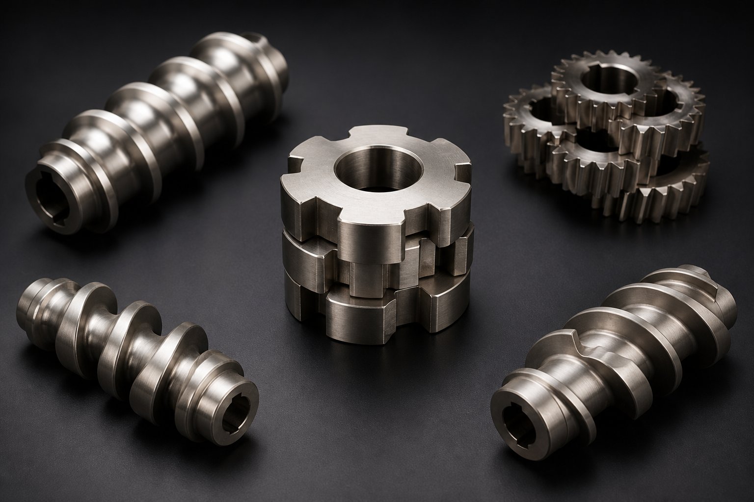
Four major categories of screw elements populate virtually every compounding twin screw extruder. Each category imposes a different mechanical effect on the material passing through it:
- Conveying elements (forward-pitch flights) — These are helical, flighted elements that transport material downstream. They come in various pitches: a large-pitch element moves material quickly but fills the channel less, while a small-pitch element slows conveying but increases fill level and local pressure. Deep-flighted conveying elements dominate the feed zone and vent zone, where the goal is transport rather than energy input. As NC State Extension research explains, channel depth decreases in the order of conveying, compression, and metering zones, reflecting each zone's shifting purpose.
- Kneading blocks (staggered disc elements) — These consist of a series of elliptical or lobe-shaped discs, each offset from the previous one by a fixed stagger angle. The stagger angle is the single most important variable controlling kneading intensity. A 30-degree forward stagger provides gentle distributive mixing with strong forward conveying. A 60-degree stagger increases shear input while reducing the forward-pumping component. A 90-degree stagger, called a neutral kneading block, eliminates forward conveying entirely, maximizing energy input and residence time in that section. Wider disc kneading elements promote dispersive mixing by forcing more material through the high-shear gap between disc tip and barrel wall, while narrow disc elements favor distributive mixing by slicing the melt into thinner streams.
- Mixing elements (gear-type, toothed, or turbine designs) — These specialized elements split and recombine flow streams repeatedly without imposing the high shear stress of kneading blocks. Toothed mixing elements, for instance, provide strong distributive mixing with essentially zero dispersive action, making them ideal for blending heat-sensitive additives or achieving color homogeneity after the primary kneading section.
- Reverse (left-hand) elements — These are conveying elements or kneading blocks with a backward pitch that actively push material upstream. The result is a flow restriction that increases fill level, builds local pressure, and extends residence time. Reverse conveying elements create the strongest restriction, while reverse kneading blocks offer a somewhat less aggressive alternative. Both types serve a critical structural role: they form the melt seals required for effective vacuum degassing and help ensure complete melting by preventing under-processed material from bypassing the kneading zone.
Sounds like a simple parts catalog? It is, until you realize that the sequence in which these elements appear on the shaft matters just as much as the elements themselves.
The Logic Behind Screw Configuration Design
A compounding extruder screw profile is not assembled randomly. Every element placement follows a cause-and-effect rationale rooted in what the material needs at that specific point in its journey.
Consider the melting section. As detailed analyses of melting-zone design show, a typical configuration begins with a mild 30-degree forward kneading block that eases material from the conveying section into the shear zone without abrupt flow disruption. Following elements escalate in intensity: 60-degree kneading blocks initiate aggressive melting, and 90-degree neutral blocks at the end of the sequence act as a melt dam, ensuring that every particle has fully transitioned to the molten state before moving downstream.
Why do reverse elements appear just upstream of vent ports? Because vacuum degassing only works when the vent zone operates at low pressure with a partially filled barrel. A reverse-pitch element immediately before the vent creates a melt seal, a pressurized plug of material, that isolates the low-pressure vent zone from the higher-pressure zones on either side. Without that seal, vacuum would pull melt backward or draw air in from upstream, defeating the purpose entirely.
Configuration philosophy also shifts depending on the processing goal. A screw designed for aggressive filler dispersion in a masterbatch line might stack multiple wide-disc kneading blocks at high stagger angles, accepting higher melt temperatures in exchange for thorough agglomerate breakdown. A screw for a heat-sensitive bioplastic, on the other hand, might use narrow-disc kneading elements at lower stagger angles separated by short conveying sections. These conveying "spacers" give the material a chance to cool slightly and redistribute before entering the next shear zone, preventing thermal runaway.
As Technovel's engineers observe, the same extruder can behave in completely different ways once the screw formation is changed. On the production floor, engineers often describe this iterative design process as something closer to tuning an instrument than specifying a machine. You adjust one element, run trials, evaluate melt temperature and product quality, and refine. Over time, each formulation earns its own optimized screw profile, documented and stored for the next production campaign.
What this iterative process reveals is that screw elements are only half the equation. Their geometry, the diameter, pitch, flight depth, and helix angle of each element, determines the quantitative intensity of the effects described above. Those geometry parameters are the engineering variables that translate configuration logic into measurable processing outcomes.
Screw Geometry Parameters and Their Processing Impact
Choosing the right screw elements and arranging them in the correct sequence gets you halfway to a successful process. The other half lives in the numerical dimensions of those elements: how long the screw is relative to its diameter, how deep the channels are, how tightly the flights are spaced, and what angle the helix follows as it wraps around the shaft. These geometry parameters are the knobs that translate configuration logic into measurable shear rates, residence times, pressure profiles, and throughput capacities.
Yet most discussions of twin screw extruder geometry stop at vague statements like "higher L/D means more processing." That is true, but it is not useful until you understand why it is true and what trade-offs come with it. Below, each critical parameter is defined, given its typical range, and connected to the processing outcomes it directly controls.
Key Geometry Parameters Defined
Five geometry parameters shape virtually every processing decision an engineer makes when specifying or optimizing a twin-screw extruder machine. The table below consolidates their definitions, common values, and primary effects in one reference.
| Parameter | Definition | Typical Range | Primary Processing Effect |
|---|---|---|---|
| L/D Ratio | Ratio of the screw's functional length to its barrel bore diameter | 32:1 to 52:1 (compounding); 20:1 to 30:1 (simpler applications) | Determines the number of functional zones, total residence time, and available barrel length for melting, mixing, venting, and pressure buildup |
| Screw Diameter | Outer diameter of the screw flight, measured across the widest point of the thread | 12 mm (laboratory twin screw extruder) to 300+ mm (large production lines) | Sets throughput capacity; extrusion volume scales roughly with the square of diameter |
| Flight Depth (Channel Depth) | Radial distance from the screw root to the flight tip | Varies by zone; deeper in feed section, shallower in metering section | Controls channel volume, shear rate, heat transfer, and pressure generation capability |
| Pitch | Axial distance between consecutive flight crests (one full turn of the helix) | 0.5D to 1.5D (expressed as a fraction of screw diameter) | Governs conveying speed, fill level, and residence time per unit length |
| Helix Angle | Angle between the screw flight and a plane perpendicular to the screw axis | 15° to 30° depending on material form and zone function | Balances forward conveying force against transverse mixing and groove volume |
How Screw Geometry Controls Shear, Pressure, and Throughput
Numbers on a spec sheet only become meaningful when you understand the cause-and-effect chains they trigger. Here is how each parameter translates into real processing outcomes, and where the trade-offs hide.
L/D ratio is the most frequently cited specification for any double screw extruder machine, and for good reason. A longer screw relative to its diameter provides more barrel length for functional zones. You can fit additional kneading sections for tougher dispersion tasks, insert multiple venting ports for heavily contaminated feedstocks, or add extended mixing sections for reactive processes that need longer dwell time. Enhanced L/D ratios combined with optimized thermal gradients facilitate superior polymer blending and plasticization because the material spends more time under controlled shear and heat conditions. Modern compounding lines routinely use 48:1 or even 52:1 ratios when processing complex multi-additive formulations. However, extending L/D is not free. Longer screws demand more drive torque, tighten manufacturing tolerances to prevent shaft deflection, and increase power consumption. For thermally sensitive polymers like PVC, a shorter L/D is actually preferred to avoid excessive residence time that would cause degradation.
Screw diameter is the primary lever for scaling throughput. Because the cross-sectional area of the screw channel, and therefore the volume of material it can hold, grows with the square of the diameter, even modest increases in diameter yield substantial output gains. A benchtop twin screw extruder with a 16 mm diameter might produce 2 to 5 kg/hr for formulation development, while a 92 mm production machine handles several hundred kg/hr of the same compound. The scaling challenge lies in maintaining equivalent shear rates and residence times as diameter grows, a problem that computational scaling-up research addresses through multi-objective optimization of speed, temperature, and geometry ratios. For screws with smaller diameters, a stress analysis becomes essential if high L/D ratios and elevated screw speeds are planned, since the shaft must withstand increased torque without mechanical failure.
Flight depth creates a deliberate gradient along the screw's length. In the feed zone, deep channels accommodate bulky, low-bulk-density solids and maximize the volume of material captured per revolution. A deep feed section groove enhances the screw's ability to convey material, but if made excessively deep, the screw root thins and becomes vulnerable to shear failure under high torque. Moving downstream into the metering section, shallower channels squeeze the now-molten polymer into a thinner layer. This increases shear rate, improves barrel-to-melt heat transfer, and builds the pressure needed to push material through the die. The key trade-off is straightforward: shallower channels generate more pressure and shear but reduce volumetric capacity. Engineers optimize this gradient to match the material's melting behavior and the required die pressure.
Pitch directly controls how fast material advances per screw revolution and how full the channel becomes at a given feed rate. A large-pitch element moves material quickly, which reduces local fill level and residence time. That is useful in feed zones and vent zones where you want rapid transport and low pressure. A tight-pitch element slows the material, increases fill, and builds pressure, exactly what the metering zone demands. Widening the groove narrows the screw thread and expands channel volume, boosting extrusion output while reducing rotational friction. In practice, engineers select pitch values as fractions of the screw diameter, typically ranging from 0.5D for restrictive metering sections to 1.5D for open, high-throughput conveying zones.
Helix angle is the geometric cousin of pitch, but it more directly governs the balance between axial thrust and transverse flow. A steeper helix angle increases the forward-pushing component of the flight, moving material faster down the barrel. A shallower angle increases the time material spends circulating within each channel, enhancing cross-channel mixing but reducing conveying efficiency. For the feeding section, a 30-degree helix angle is most suitable for powder materials, while approximately 17 degrees works best for spherical or cylindrical granules. In the metering section, theoretical analysis shows maximum extrusion flow at around 30 degrees, though practical machining considerations often lead to slightly different values.
What ties all five parameters together is a simple reality: none of them operates in isolation. Increasing L/D gives you more barrel real estate, but you need the right combination of pitch, flight depth, and helix angle within each zone to use that real estate effectively. A longer screw filled with improperly sized elements will waste energy and residence time rather than improve product quality. This interdependence is precisely why experienced engineers treat screw geometry specification as a system-level design problem, not a parameter-by-parameter checklist.
Screw geometry defines what happens inside the flights. The barrel surrounding those flights, however, is far from a passive container. Its segmented construction, temperature control capability, and functional ports for venting and side feeding play an equally active role in shaping the final product.
The Role of Barrel Design in Twin Screw Extrusion
Think of the twin screw barrel as the other half of a conversation. The screws do the talking, imposing shear, conveying force, and pressure on the material, but the barrel answers back with thermal energy, surface friction, and strategically placed openings that let material in, volatiles out, and additives enter exactly where they are needed. Strip away the barrel's active contributions and even the most brilliantly configured screw profile falls flat. Temperature runs out of control, volatiles have nowhere to escape, and fillers cannot be introduced downstream.
Yet in most discussions of the working principle of twin screw extruders, the barrel gets reduced to "a heated metal tube." That oversimplification misses how barrel segment modularity, liner material selection, thermal management, and functional port placement each play a direct role in shaping product quality and process flexibility.
Modular Barrel Segments and Functional Ports
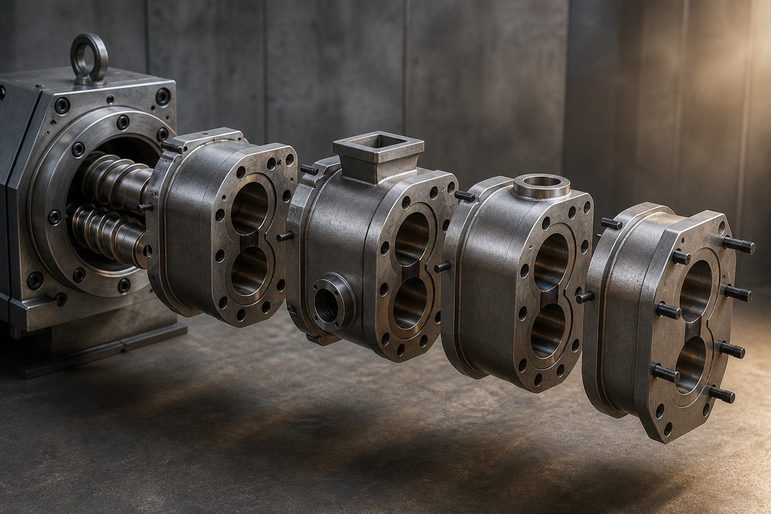
Unlike a single-screw extruder, where the barrel is often a single continuous cylinder, a co-rotating twin screw and barrel assembly is built from individual segments bolted together in series. Most twin screw extruder manufacturers offer systems with ten, eleven, or twelve modular barrel sections, each one independently configurable for a different processing function. This modular architecture means that rearranging barrel segments can transform the same machine from a compounding line into a devolatilization system or a reactive extrusion platform, without purchasing new equipment.
Each barrel segment contains the characteristic figure-eight bore that matches the twin screw geometry. Beyond that shared feature, segments diverge into several functional types:
- Closed barrel segments — Fully enclosed sections with no external openings. These make up the majority of the barrel assembly, providing a sealed environment for melting, mixing, and pressure buildup. All sides of the closed barrel are temperature-controlled via both heating and cooling channels.
- Open (feed) barrel segments — Sections with an opening at the top, positioned at the barrel's first station to accept raw material from the gravimetric feeder. For low-bulk-density powders that entrain significant air, engineers sometimes place a second open barrel upstream of the feed barrel to serve as a rear vent, allowing displaced air to escape without blocking the feed opening.
- Venting barrel segments — Open-topped sections positioned over low-pressure screw zones for atmospheric or vacuum degassing. Placement is critical: a vent port must align with a screw section where reverse elements have created a melt seal upstream, ensuring the barrel is only partially filled and the vacuum can draw volatiles from the exposed melt surface. For extruders with an L/D of 40 or more, vacuum vents are typically placed in the second or third barrel section upstream of the die to balance volatile removal efficiency against the risk of melt erupting into the vent under high head pressure.
- Side-feeder barrel segments — These sections feature a secondary figure-eight opening on the barrel's side wall, connecting to a cramming-type side feeder. Fillers like calcium carbonate, glass fibers, or pigment concentrates are introduced here, directly into the already-molten polymer stream. Feeding downstream rather than at the throat protects fragile additives from the intense shear of the melting zone and prevents abrasive fillers from accelerating wear on upstream screw elements. A small atmospheric vent is often integrated upstream of or combined with the side-feeder barrel to release displaced air as the filler enters.
- Liquid injection barrel segments — Closed segments fitted with a small threaded port on top, connected to a needle valve and plunger pump. Liquid additives, plasticizers, coupling agents, or reactive monomers are metered directly into the melt stream at a precisely controlled rate, ensuring uniform distribution without flooding the channel.
Imagine you need to process a highly filled polyolefin compound containing 60% calcium carbonate. You would configure the barrel with a feed opening at position one, closed segments through the melting zone, a side-feeder barrel at position five or six for the mineral filler, additional closed mixing segments, a vacuum vent barrel near position nine, and a final closed metering segment before the die. Change the formulation to a moisture-sensitive nylon that requires aggressive devolatilization, and you might swap the side-feeder barrel for a second vacuum vent, doubling the degassing capacity without altering the screws at all.
This interchangeability is the practical payoff of modular barrel design. It turns a single twin screw extruder into a flexible processing platform whose capabilities expand every time you reconfigure the barrel layout to match a new application.
Barrel Liners, Heating, and Cooling Systems
The inside surface of each barrel segment endures relentless mechanical and chemical assault. Abrasive fillers like glass fiber and calcium carbonate grind against the bore wall, corrosive polymers like fluoroplastics attack metal surfaces chemically, and high processing temperatures accelerate both forms of degradation. The twin screw barrel liner is the first line of defense, and choosing the right liner material for your application directly impacts equipment longevity, maintenance costs, and even product purity.
Common liner options span a wide range of performance and cost:
- Nitrided steel (38CrMoAl) — A nitrogen-hardened alloy with high surface hardness and good corrosion resistance. The hard outer case sits over a tougher core, providing a practical balance between wear resistance and structural integrity. This is a standard choice for general-purpose compounding without extreme abrasive or corrosive demands.
- Bimetallic liners (e.g., iron-chromium-nickel carbide alloys) — A wear-resistant alloy sleeve centrifugally cast into the barrel bore, reaching hardness levels of HRC 60 to 64. These liners excel in applications involving glass fiber reinforcement or mineral fillers that would quickly erode softer steels.
- Tungsten carbide or high-chromium powder alloy sleeves — Top-tier wear resistance for the most abrasive formulations. Often manufactured as integral sleeves using powder metallurgy, these liners offer extremely long service life but come at a premium cost.
- Nickel-based alloy liners (HaC alloys) — Engineered for superior corrosion resistance, particularly in fluoroplastics processing where standard steels would deteriorate rapidly.
- 316L stainless steel barrels — Corrosion-proof and rust-resistant, these are the standard in food-grade and pharmaceutical extrusion, where contamination risks must be eliminated.
Selecting the right liner is not a one-size-fits-all decision. A recycling line processing post-consumer plastics with metal contaminants needs aggressive abrasion resistance. A food-grade extrusion line needs FDA-compliant stainless steel. A fluoropolymer line needs corrosion-first metallurgy. For teams sourcing replacement barrel segments or liners engineered for specific demands across pipe, profile, sheet, pelletizing, and recycling applications, suppliers like NANHAIYA provide screw barrel support tailored to the processing environment, helping match liner grade and barrel type to the formulation's wear and corrosion profile.
Thermal management is the barrel's other active contribution to the working principle. Each modular segment is equipped with its own set of cartridge heaters, typically electric resistance elements embedded in the barrel wall, and dedicated cooling channels that circulate water or oil. This arrangement creates independent temperature zones along the barrel length, allowing engineers to build a precise thermal profile from feed throat to die.
Why does zone-by-zone temperature control matter so much? Because the optimal barrel temperature changes with the material's physical state. In the feed zone, cooling prevents premature melting and maintains solid-state friction for reliable conveying. In the melting zone, barrel heat supplements shear-generated viscous dissipation to accelerate the solid-to-melt transition. In the mixing zone, barrel temperature may be set slightly below melt temperature to extract excess shear heat and prevent degradation. And in the metering zone, precise temperature holds melt viscosity in the narrow window needed for stable die flow.
Closed barrel segments, fully surrounded by heating and cooling channels on all sides, provide the tightest thermal control. Open barrels and side-feeder barrels sacrifice some thermal surface area for their functional ports, which is why engineers avoid placing these segments in zones where temperature precision is most critical, such as the plasticizing section.
The barrel's thermal, structural, and functional port contributions all circle back to one principle: the barrel is an active processing partner, not a passive shell. Its configuration must be designed in concert with the screw profile, the same way an instrument's resonating body is designed in concert with its strings. Change one without considering the other, and the result is a system that underperforms its potential.
With both halves of this partnership, screws and barrel, now fully detailed, the natural question shifts from how the machine works to what it can do. The same intermeshing, self-wiping, thermally managed platform serves industries as different as polymer compounding and pharmaceutical manufacturing, each one leveraging a different facet of the core working principle.
Industry-Specific Applications of Twin Screw Extrusion
A single machine platform, built on intermeshing geometry, self-wiping action, and starve-fed energy control, somehow produces automotive-grade glass-filled nylon, food-contact recycled polyethylene pellets, pharmaceutical solid dispersions, and puffed breakfast cereals. How? Each industry leans on a different facet of the core working principle and adapts screw configuration, barrel layout, and thermal profile to match its unique processing demands.
The applications below illustrate this adaptability. For each one, you'll see which mechanical principle carries the most weight and how engineers reshape the same hardware to serve radically different goals.
- Polymer compounding and masterbatch — relies primarily on intensive dispersive and distributive mixing via kneading blocks
- Plastic recycling and pelletizing — depends on venting and degassing zones for volatile and moisture removal
- Pharmaceutical hot-melt extrusion — leverages narrow residence time distribution and precise thermal control
- Food processing — exploits shear-heating and pressure-driven cooking and texturization
Polymer Compounding and Masterbatch Production
Polymer compounding is the application that twin-screw extruders were essentially born to serve. The task sounds straightforward: blend a base polymer with pigments, mineral fillers, glass fibers, flame retardants, or stabilizers to produce a homogeneous compound. In practice, the challenge is enormous. Pigment agglomerates as small as a few microns must be shattered and distributed uniformly throughout the matrix. Glass fibers need thorough wetting by the melt without being broken to lengths too short to reinforce anything. Flame retardant particles must be dispersed evenly at loading levels sometimes exceeding 60% by weight.
The aspect of the working principle that dominates here is mixing intensity and control. A plastic twin screw extruder configured for compounding typically features multiple kneading block sections with progressively aggressive stagger angles, 30 degrees for initial softening, 60 degrees for primary dispersion, and 90-degree neutral blocks to maximize energy input where agglomerates are most stubborn. Between these kneading zones, short conveying sections allow the melt to redistribute and cool slightly before encountering the next high-shear region.
Side-feeding ports, positioned downstream of the primary melting zone, introduce abrasive fillers or fragile fibers directly into the already-molten polymer. This protects both the additives and the upstream screw elements from unnecessary wear or damage. As Nanoscience Instruments explains, twin-screw extruders are commonly used in polymer compounding for blending polymers with fillers, additives, and stabilizers to produce engineering plastics, high-performance composites, and biodegradable polymers. Starve-fed operation is critical in compounding because it lets operators raise screw speed, and therefore specific mechanical energy, without changing throughput. That independent control is what makes it possible to fine-tune dispersion quality on the fly during production.
Recycling, Pelletizing, and Specialty Applications
Plastic recycling and pelletizing push the working principle in a different direction entirely. The incoming feedstock is no longer pristine pellets with consistent properties. It is shredded post-consumer film, washed bottle flake, or mixed-color regrind containing residual moisture, odor-causing volatiles, paper label fragments, and fluctuating melt viscosities.
Here, the venting and degassing capability of a twin screw plastic extruder becomes the most critical processing feature. Vacuum vent ports, positioned over low-pressure screw zones sealed by reverse elements, strip moisture that would otherwise cause hydrolytic chain scission in condensation polymers like PET and nylon. They also extract volatile organic compounds responsible for off-odors that disqualify recycled material from food-contact or consumer goods applications. Industry reporting from Waste Management World highlights that co-rotating twin-screw extruders have become the consensus platform for demanding recycling applications, particularly above roughly one tonne per hour throughput, because of their ability to simultaneously achieve excellent homogenization, effective degassing, and minimal product degradation.
Screw configurations for recycling are deliberately gentler than those used in aggressive compounding. Kneading sections use moderate stagger angles and shorter overall lengths to minimize shear heating on polymer chains that have already been thermally stressed in their first life. The goal is to re-melt and clean, not to pulverize. Modularity matters here more than in almost any other application: as recycling equipment specialists note, when incoming material changes character, the screw profile can be physically reconfigured rather than replaced wholesale, with a complete screw change achievable within one to two hours on a medium-sized machine.
Pharmaceutical hot-melt extrusion (HME) represents the opposite end of the scale spectrum but leans on the same underlying mechanics. In pharmaceutical applications, twin-screw extruders disperse active pharmaceutical ingredients (APIs) into thermoplastic polymer carriers to form amorphous solid dispersions that dramatically improve the solubility of poorly water-soluble drugs. A comprehensive review published in AAPS PharmSciTech describes how HME converts components into an amorphous product with uniform density by operating above the polymer's glass transition temperature, achieving molecular-level mixing without solvents.
The working principle features that matter most here are narrow residence time distribution and precise thermal control. Self-wiping prevents heat-sensitive APIs from lingering in stagnant zones where thermal degradation would destroy efficacy. Typical residence times range from just 5 seconds to 10 minutes depending on the screw speed, feed rate, and L/D ratio. Independent temperature zones along the barrel allow engineers to hold processing temperatures within a few degrees of the target, preventing amorphous-to-crystalline reversion that would undo the solubility enhancement. Screw configurations for pharmaceutical HME tend to use shorter kneading sections with moderate intensity, balancing the need for intimate drug-polymer mixing against the risk of thermally degrading the API.
Food processing rounds out the application spectrum by exploiting shear-heating and pressure-driven transformation in ways that look nothing like plastics processing, yet rely on identical principles. Twin-screw extruders cook, texturize, and shape products ranging from breakfast cereals and savory snacks to plant-based protein analogs. The screws apply enough shear energy to gelatinize starch, denature proteins, and develop the expanded, porous textures that define puffed and extruded snack foods. Moisture flashing at the die exit creates the characteristic expansion that turns dense dough into a light, crispy product.
Co-rotating twin-screw extruders dominate food extrusion for the same reasons they dominate compounding: superior mixing homogeneity ensures uniform texture and flavor distribution, while starve-fed operation gives food engineers independent control over the mechanical cooking energy applied to the formulation. Screw configurations for food extrusion balance conveying, kneading, and pressure-building zones much like polymer processing, but with the added complexity of managing water content, starch conversion, and protein cross-linking simultaneously.
Across all four of these industries, a pattern emerges. The fundamental mechanics never change: positive displacement, self-wiping, modular screw and barrel design, and decoupled speed-feed control remain constant. What changes is which principle each application emphasizes and how the screw configuration is tuned to prioritize that principle. Compounding demands mixing intensity. Recycling demands degassing. Pharma demands thermal precision and residence time uniformity. Food demands controlled shear-cooking. The twin-screw platform's ability to serve all four from a single mechanical architecture is, ultimately, the strongest practical validation of its working principle.
Knowing how the machine adapts to different industries, however, only tells half the operational story. On the production floor, the real test of principle-level understanding comes when something goes wrong. A degradation spike, a poorly dispersed batch, or a surging die output each points back to a specific zone and a specific mechanism, and diagnosing the root cause requires tracing symptoms back through the very principles covered in this article.
Troubleshooting Twin Screw Extruder Issues Through Working Principles
Your melt temperature is climbing, pellets are coming out porous, and the vacuum vent is spitting polymer onto the barrel top. Where do you even start? Most operators reach for the nearest dial, adjusting screw speed or barrel temperature based on instinct. But every symptom on a twin screw extruder traces back to a specific zone and a specific mechanism. Diagnose the root cause at that level, and the corrective action becomes obvious rather than experimental.
Experienced troubleshooters treat the process like a medical diagnosis. As industry practitioners describe it, the first strategic step is determining whether the problem is chronic, appearing every time a formulation runs, or transient, a sudden departure from previously stable operation. Chronic issues usually point to fundamental flaws in screw configuration or operating parameters. Transient problems demand investigation into what variable changed: a worn element, a feeder drift, a failed heater band, or even a shift in ambient humidity affecting hygroscopic resins.
The five most common processing failures on twin screw extruders, and the principle-level reasoning behind each, are mapped in the matrix below.
Connecting Process Problems to Working Principle Zones
Each row in this table links a visible symptom to the functional zone where it originates, explains the root cause in terms of the working principle, and prescribes a targeted corrective action. Use it as a diagnostic framework rather than a random checklist.
| Symptom | Probable Zone | Root Cause (Linked to Working Principle) | Corrective Action |
|---|---|---|---|
| Material degradation (discoloration, reduced molecular weight, odor) | Melting / Kneading zone | Excessive residence time or shear energy input in the kneading section. SME too high due to aggressive kneading block stagger angles, excessive screw speed relative to feed rate, or too many restrictive elements creating unnecessary melt holdup. | Reduce screw speed, increase feed rate to lower SME, replace 90-degree kneading blocks with 60-degree or 30-degree elements, shorten the overall kneading section length, or lower barrel temperatures in the mixing zone. |
| Poor dispersion or unmixed agglomerates (visible specks, inconsistent color, failed physical property tests) | Mixing / Kneading zone | Insufficient kneading intensity. Kneading block stagger angles too narrow for the required dispersive action, total kneading section too short, or the material bypasses the high-shear zone due to partially worn elements that no longer generate adequate shear stress. | Increase kneading block stagger angle (e.g., switch from 30-degree to 60-degree), add wider-disc kneading elements for stronger dispersive action, extend the mixing section, or increase screw speed to raise shear rate. Inspect kneading elements for wear. |
| Surging or inconsistent output (fluctuating die pressure, pulsating strands, weight variation in pellets) | Metering / Pumping zone | Pressure instability caused by inconsistent feed rate from the gravimetric feeder, worn screw flights in the pressure-building section that reduce pumping efficiency, or barrel wear that increases radial clearance and allows melt to slip backward past the flights. | Recalibrate the loss-in-weight feeder, verify feeder screw type matches the material form, inspect and replace worn metering-zone conveying elements, and check barrel bore dimensions in the pumping section against original tolerances. |
| Vent flow (polymer erupting from vacuum or atmospheric vent ports) | Venting / Degassing zone | The melt seal upstream of the vent is incomplete. Reverse elements may be worn, reducing their ability to generate the back-pressure needed to isolate the low-pressure vent zone. Alternatively, the backup length from the die has increased due to screen fouling or die-hole blockage, pushing filled screw into the vent opening. | Check reverse element condition and replace if worn. Reduce die or screen pressure by increasing screen area or die-hole count. Move the vacuum vent one barrel upstream if backup length is chronically too long. For foaming materials, install a mechanical vent stuffer to physically prevent melt expansion into the vent port. |
| Excessive motor load (high torque percentage, motor tripping, drive faults) | Kneading zone / Entire screw profile | Specific mechanical energy is too high for the material's viscosity. Too many restrictive elements, overly aggressive kneading sections, or insufficient barrel heating forces the motor to do all the work mechanically. Can also result from a feed-rate spike that suddenly increases fill level across restrictive screw zones. | Reduce the number or aggressiveness of kneading and reverse elements, increase barrel temperature in the melting zone to let conducted heat share the energy load, verify feed rate stability, or reduce screw speed. For high-viscosity materials, consider redesigning the screw profile with shorter kneading sections spaced by conveying elements. |
Notice a pattern? Every corrective action points back to one of the principles covered earlier in this article: adjusting SME through the speed-feed relationship, modifying element geometry to change shear intensity, or restoring the positive displacement and self-wiping characteristics that wear gradually erodes. Troubleshooting is not a separate skill from understanding the working principle. It is the working principle, applied in reverse.
One additional diagnostic distinction deserves attention. A problem that has always existed with a given formulation, what practitioners call a chronic issue, almost always signals a fundamental screw design or parameter mismatch. A problem that appears suddenly on a previously stable process, a transient issue, points to a variable that changed: a worn component, a feeder calibration drift, a failed heater band, or even seasonal humidity shifts affecting hygroscopic resins stored in outdoor silos. Separating chronic from transient narrows the investigation dramatically before you ever open the barrel.
Maintaining Screw and Barrel Performance Over Time
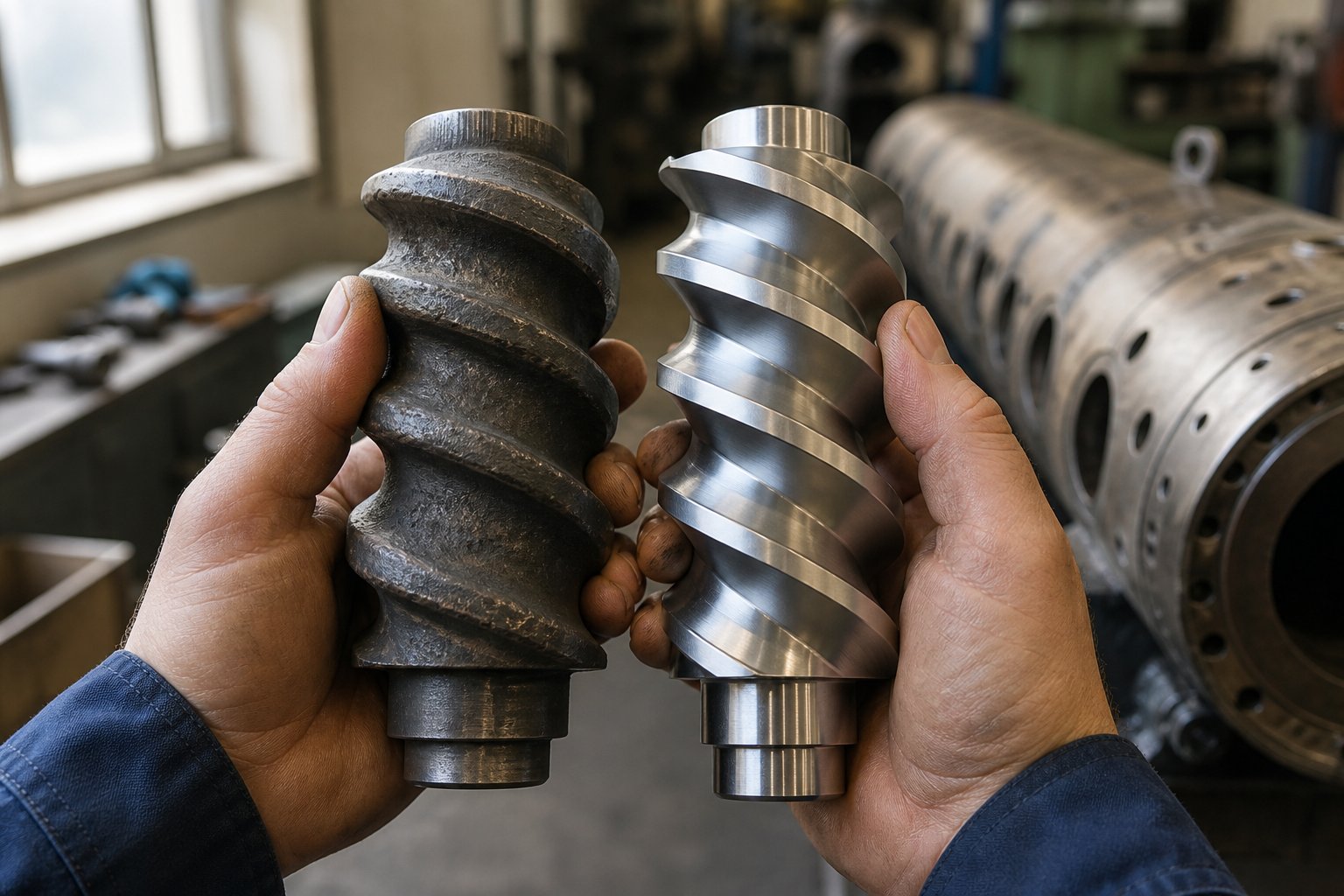
Every mechanism that makes twin screw extruders effective, self-wiping, positive displacement, intermeshing shear, depends on tight dimensional tolerances between the screw flights and the barrel bore. Over thousands of operating hours, abrasive fillers, corrosive additives, and simple metal-on-metal contact gradually widen those clearances. The consequences cascade through every zone:
- Self-wiping degrades first. As flight tips wear and the gap between screw and barrel increases, the wiping action becomes less complete. Material begins to stagnate in thin layers along the barrel wall, leading to increased residence time scatter and thermal degradation of heat-sensitive polymers.
- Conveying efficiency drops. Worn flights in the feed zone reduce intake capacity, forcing operators to lower the feed rate, a band-aid fix that directly cuts throughput. As compounding industry experts note, slowing down the feed rate offers a temporary fix, but the only true cure is replacing the worn parts.
- Pressure generation weakens. Worn metering-zone elements cannot build sufficient head pressure to push melt through the die consistently. The backup length increases, eventually reaching the vacuum vent and causing chronic vent flooding, a failure mode that worsens gradually over weeks or months.
- Dispersion quality declines. Worn kneading blocks lose the tight clearances that generate high shear stress at the disc tips. Agglomerates that were once easily broken apart now pass through intact, showing up as specks, gels, or failed dispersion tests in the finished product.
Proactive measurement is the only reliable defense. Periodically gauging screw flight outer diameters and barrel bore inner diameters against original specifications reveals wear trends before they reach the threshold where product quality or throughput suffers. Maintenance studies suggest that proactive replacement programs can reduce operating costs by 20 to 30 percent compared to reactive approaches that wait for a failure to force action.
When measurements confirm that screw elements or barrel liners have exceeded their wear limits, the corrective path is component replacement rather than wholesale machine purchase. For production teams running twin screw extruder plastic compounding, recycling, or pelletizing lines, sourcing precision-manufactured replacement elements and barrel liners engineered to original specifications is critical for restoring the intermeshing clearances, self-wiping efficiency, and pressure-building capability that define the machine's working principle. Suppliers like NANHAIYA offer screw barrel support across pipe, profile, sheet, pelletizing, and recycling applications, providing a practical sourcing path for teams that need to bring worn screw extruders back to design-level performance without extended downtime.
Ultimately, every topic covered in this article, from positive displacement and self-wiping geometry through zone-by-zone material transformation, screw element sequencing, barrel modularity, and industry-specific adaptation, converges on a single insight: the working principle is not an abstract concept confined to textbooks. It is the living framework that governs every product quality outcome, every throughput target, and every troubleshooting decision on the production floor. Engineers who internalize that framework do not just operate twin screw extruders. They command them.
Frequently Asked Questions About Twin Screw Extruder Working Principles
1. What is the basic working principle of a twin screw extruder?
A twin screw extruder operates by rotating two intermeshing Archimedean screws inside a figure-eight-shaped barrel bore. The intermeshing flight geometry creates enclosed C-shaped chambers that positively displace material forward, while self-wiping action prevents stagnation. Material passes through distinct functional zones — feeding, melting, mixing, venting, and metering — where screw elements and barrel temperature profiles are independently configured to convey, plasticize, homogenize, degas, and pressurize the feedstock into a uniform output. Unlike single screw extruders that rely on frictional drag, twin screw machines decouple screw speed from feed rate through starve-fed operation, giving engineers independent control over shear energy input and throughput.
2. What is the difference between co-rotating and counter-rotating twin screw extruders?
Co-rotating twin screw extruders have both screws turning in the same direction, creating a figure-eight material transfer path that delivers excellent distributive and dispersive mixing. They are fully self-wiping, tolerate high screw speeds (600-1,200+ rpm), and dominate compounding, masterbatch, and reactive extrusion applications. Counter-rotating extruders spin the screws in opposite directions, generating a calendering nip effect that builds high pressure under lower shear conditions. This makes them ideal for thermally sensitive materials like rigid PVC, but structural forces on the screws limit maximum speed and throughput. Conical counter-rotating designs add progressive shear reduction as the material melts, further protecting heat-sensitive formulations during profile and pipe extrusion.
3. Why do twin screw extruders use starve feeding instead of flood feeding?
Starve feeding decouples throughput from screw speed, which is a critical advantage unique to twin screw extruders. A gravimetric feeder meters material into the barrel at a controlled rate independent of screw rpm. This gives operators two separate control levers: feed rate sets throughput (kg/hr), while screw speed controls the shear energy applied per kilogram, expressed as specific mechanical energy (SME). This decoupling allows engineers to increase dispersion intensity without changing output, or maintain gentle processing while maximizing throughput. Starve feeding also enables downstream side stuffing of fillers and fibers into mid-barrel positions, since the low pressure gradient in partially filled screw channels does not resist secondary feeding.
4. What are the main types of screw elements in a twin screw extruder?
Four major screw element categories serve distinct functions. Conveying elements are helical flights that transport material forward, available in various pitches for controlling speed and fill level. Kneading blocks are staggered disc elements that impose shear for melting and mixing — their stagger angle (30, 60, or 90 degrees) determines intensity. Mixing elements such as gear-type or toothed designs split and recombine flow streams for distributive homogenization without high shear stress. Reverse (left-hand) elements push material backward, creating flow restriction, pressure buildup, and melt seals essential for degassing zones. The sequence of these elements along the shaft defines each processing zone's function and determines the overall screw configuration's performance.
5. How do you troubleshoot common twin screw extruder problems using working principles?
Effective troubleshooting traces visible symptoms back to specific processing zones and mechanisms. Material degradation typically originates in the kneading zone from excessive SME — corrected by reducing screw speed, increasing feed rate, or using less aggressive kneading blocks. Poor dispersion signals insufficient mixing intensity, requiring higher stagger angles or additional kneading elements. Output surging points to pressure instability in the metering zone from feeder drift or worn flights. Vent flow indicates an incomplete melt seal upstream of the vent port, often caused by worn reverse elements. Excessive motor load suggests too many restrictive elements for the material's viscosity. Separating chronic issues (design flaws) from transient ones (changed variables like worn components) narrows the diagnosis before opening the barrel. Sourcing precision replacement screw elements and barrel liners from specialists like NANHAIYA (nhyscrews.com) restores worn clearances to design specifications.
Written by
Nanhaiya Technical Team
Zhoushan Nanhaiya Plastic Machinery Co., Ltd.
The Nanhaiya technical team supports screw and barrel manufacturing projects through application review, technical communication, custom manufacturing coordination, and production and quality control.
Discuss Your Application
Related Articles
More insights on screw barrel technology and plastics processing.

Extruder Machine Decoded: From Raw Pellet To Finished Product
Oct 6, 2026
Learn how an extruder machine works, compare single-screw vs. twin-screw types, and get expert guidance on specs, troubleshooting, and selection.
Read Article
PE Pipe Making Machine Decoded: From Raw Resin to Flawless Pipe
Oct 4, 2026
Learn how a PE pipe making machine works, from resin to finished pipe. Covers components, material grades, automation, troubleshooting, and buyer selection tips.
Read Article
PVC Profile Making Machine Decoded: From Raw Resin To Profit
Oct 3, 2026
Learn how a PVC profile making machine works — extrusion process steps, key technical parameters, die design, calibration methods, maintenance, and total cost of ownership.
Read ArticleLooking for something else?
Search by material, symptom or product and jump straight to the relevant page.
These are navigation suggestions based on keyword matching — not a quotation, not a delivery commitment, and not a substitute for engineering review. Final specification is confirmed by our engineers against your drawings and processed material.
Need help with screw barrel selection?
Share your machine model, processed material and application. Our team can help with pricing and technical support.