

What Is Wood Plastic Composite Extrusion
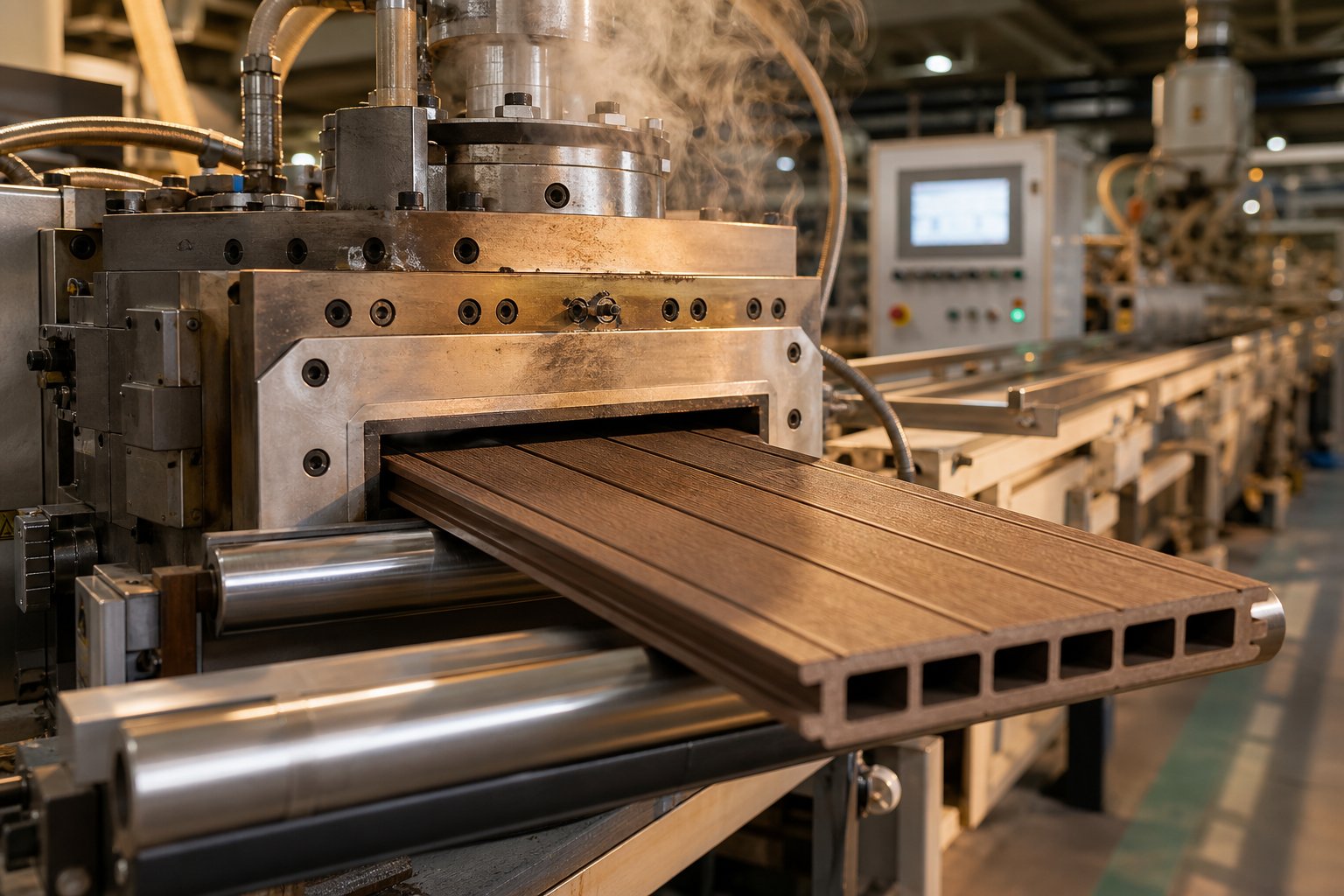
Imagine a material that borrows the natural stiffness of wood and the moisture resistance of plastic, then gets shaped into perfectly uniform profiles at industrial speed. That material is a wood plastic composite, and the process that makes it possible is extrusion.
What WPC Means and Why It Matters
So, what does WPC stand for? WPC is the abbreviation for Wood Plastic Composite — a hybrid material that blends wood fibers or wood flour with a thermoplastic polymer matrix such as polyethylene, polypropylene, or PVC. To define WPC more precisely, you can think of it this way:
Wood plastic composite extrusion is a continuous thermoplastic processing method in which dried wood fibers or flour are melt-blended with a polymer matrix and functional additives inside a heated extruder, then forced through a shaped die to produce solid or hollow profiles with consistent cross-sections.
Why blend these two very different material families at all? Wood fibers contribute stiffness, a lower raw material cost, and a natural aesthetic. The plastic matrix contributes moisture resistance, dimensional stability, and processability. Together, wood-plastic composites deliver performance neither material achieves alone — a durable, low-maintenance product that resists rot, insects, and UV degradation while still looking and feeling like real wood.
This combination is what makes WPC wood plastic composite products so attractive for decking, cladding, fencing, and flooring applications worldwide. The result is essentially plastic wood — engineered to outperform both raw lumber and pure polymer profiles in outdoor and high-wear environments.
Why Extrusion Dominates WPC Manufacturing
You might wonder why extrusion, rather than injection molding or compression molding, is the go-to method for producing these composites. The answer comes down to three practical advantages:
- Consistent cross-sections: Extrusion produces continuous linear profiles with uniform wall thickness and geometry — exactly what is needed for decking boards, railing systems, and cladding planks.
- High throughput: A well-tuned extrusion line runs continuously, generating hundreds of kilograms per hour of finished product without the cycle-time interruptions inherent in batch-based molding.
- Long profile capability: Unlike injection molding, which is limited by mold cavity size, extrusion can produce profiles in virtually any length, then cut them to specification downstream.
These characteristics make extrusion the dominant manufacturing method for wood plastic composite material across both North American and global markets. This guide is built for production engineers and plant managers who need practitioner-level depth — covering raw material selection and fiber preparation, compounding and additive systems, extruder architecture, process parameter optimization, defect troubleshooting, and post-extrusion finishing. Every section ahead focuses on decisions you can act on at the production floor level.
Essential Raw Materials and Additive Systems for WPC
The performance of any wood polymer composite starts with a single decision: which polymer will serve as the matrix? That choice cascades into every downstream variable — processing temperatures, additive requirements, mechanical behavior, and the end markets you can realistically serve. Yet most production teams inherit a formulation without fully understanding why one plastic composite material outperforms another in a given application. Let's fix that.
Polyolefins vs. PVC as the Matrix Polymer
PE-based WPC material dominates the North American decking and fencing market, and for good reason. High-density polyethylene (HDPE) melts at relatively low temperatures (around 130-170 °C in practice), flows easily around wood particles, and tolerates the slight moisture that even well-dried fibers carry into the barrel. LDPE shares that forgiving melt behavior but produces softer, more flexible profiles with lower stiffness — a trade-off that limits its use to niche applications rather than structural decking.
Polypropylene (PP) steps up the stiffness ladder. PP-based wood plastic composite material generally delivers higher flexural strength and a higher heat deflection temperature than PE-based equivalents, making it attractive for automotive interior panels and load-bearing profiles. The catch? PP requires slightly higher processing temperatures (typically 160-190 °C at the die), and its melt viscosity is more sensitive to wood fiber loading. Research on HDPE- and PP-based WPCs has shown that tensile modulus increases linearly with wood content in both polymer types, but PP composites can struggle with extensibility at higher filler fractions when processing temperatures are kept low to protect the wood fibers.
PVC-based WPC occupies a different space entirely. PVC's rigid amorphous structure yields profiles with excellent dimensional stability, sharp corner definition, and a smooth surface finish — qualities prized in window and door profiles, interior trim, and sheet applications. However, PVC has a narrow processing window and begins to degrade thermally near the same temperatures that threaten wood fibers (above approximately 200 °C). That overlap demands tighter temperature control and gentler shear during extrusion, which is why PVC-based formulations pair so naturally with conical twin-screw extruder architectures.
| Property | HDPE | PP | PVC |
|---|---|---|---|
| Processing Temperature Range | 130-170 °C | 160-190 °C | 150-185 °C |
| Wood Fiber Compatibility | Good — forgiving melt flow accommodates high fiber loading | Moderate — higher viscosity sensitivity at elevated wood content | Good — but requires careful thermal management to avoid fiber degradation |
| Flexural Modulus Range (Typical WPC) | 1,000-2,500 MPa | 1,500-3,500 MPa | 2,000-4,000 MPa |
| Water Absorption Tendency | Low to moderate | Low to moderate | Low |
| Primary Applications | Decking, fencing, cladding, marine boards | Automotive panels, structural profiles, furniture components | Window/door profiles, interior trim, sheet and foam-core products |
Sounds complex? The simplest way to think about it: HDPE is the workhorse for outdoor composite plastic products, PP trades some processability for higher rigidity, and PVC excels where dimensional precision and surface quality matter most.
The Role of Coupling Agents, Lubricants, and Stabilizers
Here's the fundamental chemistry challenge in every wood plastic composite formulation: wood fibers are hydrophilic — their surfaces are covered in hydroxyl groups that love water. Thermoplastics like PE, PP, and PVC are hydrophobic — they repel water and have no natural chemical affinity for cellulose. Without a molecular bridge between these two phases, the interfacial adhesion is simply too weak. You'll see poor stress transfer, reduced flexural strength, and fiber pull-out on fracture surfaces.
Coupling agents solve this problem. Maleic anhydride grafted polyethylene (MAPE) and maleic anhydride grafted polypropylene (MAPP) are the most widely used compatibilizers in WPC production. The anhydride groups react with the hydroxyl groups on wood fiber surfaces to form chemical bonds, while the polyolefin backbone entangles with the polymer matrix. The result is dramatically improved mechanical performance — research has documented bending strength increases of up to 189% when MAPE is added to high wood-content composites compared to uncompatibilized blends. For PVC-based systems, isocyanates and silane-based agents often replace maleated polyolefins as the preferred compatibilizer chemistry.
Coupling agents alone, however, are not enough to run a stable extrusion line. A complete additive package typically includes several functional categories, each solving a specific processing or performance problem:
- Coupling agents (2-5% by weight): MAPE, MAPP, silanes, or isocyanates that chemically bridge the wood-plastic interface and improve mechanical properties.
- Lubricants (3-8% by weight): External lubricants like zinc stearate and PE wax reduce friction between the melt and barrel/die surfaces, preventing die buildup and lowering screw torque. Internal lubricants such as ester-based compounds reduce melt viscosity at high shear rates.
- UV stabilizers (0.5-1% by weight): Hindered amine light stabilizers (HALS) and benzophenone absorbers protect outdoor products from photodegradation, color fading, and surface embrittlement.
- Pigments and colorants: Iron oxide, carbon black, or organic pigments provide wood-tone colors and can double as mild UV screeners.
- Biocides (0-2% by weight): Zinc borate is the most common additive for protecting the wood fiber fraction against fungal decay and mold, especially in high-humidity applications.
- Flame retardants: Added as required by building codes — particularly relevant for interior profiles and cladding where fire-spread indices must meet regulatory thresholds.
- Mineral fillers (0-10% by weight): Talc or calcium carbonate can improve stiffness, reduce material cost, and enhance surface hardness, though they also increase abrasive wear on screws and barrels.
The recommended dosage of each additive varies by polymer type, wood loading, and target application. For PE-based WPC, industry guidelines suggest 30-60% natural fiber reinforcement, 2-5% coupling agent, and 3-8% lubricant as a practical starting framework. Getting these ratios right is essential — too little coupling agent leaves fiber-matrix adhesion weak, while too much lubricant can migrate to the surface and cause delamination or printing issues downstream.
Every additive in the formulation interacts with the wood fiber preparation upstream. Fiber particle size, moisture content, and species selection all influence how effectively coupling agents bond and how lubricants flow through the melt — variables explored in depth next.
Wood Fiber Preparation That Controls Product Quality
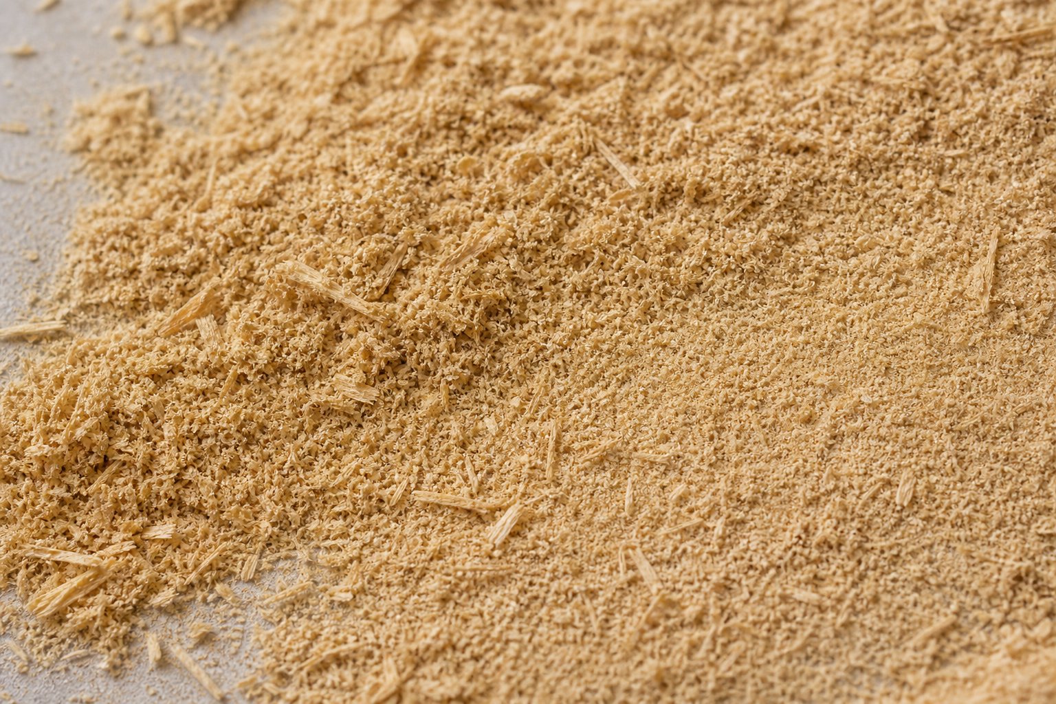
What is wood composite made of at its core? The answer is straightforward — wood fibers or flour blended into a polymer matrix. But the quality of that wood component before it ever reaches the extruder barrel determines whether you produce premium profiles or fight defects all shift long. Fiber preparation is the upstream process most production teams underestimate, yet it fundamentally controls melt viscosity, die pressure, surface finish, and mechanical performance in every wood plastic composite you extrude.
Wood Species Selection and Fiber Morphology
Softwood and hardwood fibers behave very differently inside an extruder, and the distinction matters more than most operators realize. Softwood species like pine, spruce, and fir produce flour particles with long, thin fiber bundles — a consequence of their abundant longitudinal tracheids. These higher-aspect-ratio particles contribute to improved flexural strength in the finished wood polymer product, but they also increase melt viscosity and can resist uniform dispersion if the extruder's mixing capability is inadequate.
Hardwood species like maple, oak, and poplar generate shorter, thicker particles with smoother surfaces. SEM studies of wood flour morphology confirm that hardwood particles appear more compact and less fibrous at equivalent mesh sizes, resulting in easier melt flow and lower die pressure during extrusion. However, that smoother surface also means fewer mechanical interlocking sites between fiber and matrix — making coupling agent selection even more critical for hardwood-based formulations.
Beyond species, you'll encounter a choice between virgin fiber and reclaimed material. Post-industrial sawdust, planer shavings, and small chips from secondary processing mills represent an abundant, low-cost feedstock. In the United States alone, wood processing facilities generate over 15 million cubic meters of wood residues annually. These residues are typically clean, uniform, and already partially dried — making them ideal starting material for wood filled plastic production. Virgin fiber offers tighter control over species consistency and contamination levels, but reclaimed waste dramatically reduces raw material cost and supports sustainability goals.
The critical takeaway here is that fiber morphology — particle shape, aspect ratio, and surface roughness — is not just an academic curiosity. It directly governs how your melt flows through the die, how much torque your screw requires, and whether your finished wood plastic composites meet mechanical specifications.
Particle Sizing, Moisture Control, and Pre-Blending
Imagine feeding coarse wood chips directly into your extruder hopper. The result would be uneven melt flow, visible fiber clumps on the profile surface, and inconsistent mechanical properties throughout the cross-section. Proper particle size reduction and classification are non-negotiable steps in producing quality WPC.
Industry practice targets particle sizes in the 40-100 mesh range (420 down to 149 micrometers) depending on the application. Larger particles in the 40-60 mesh range (420-250 micrometers) generally provide better melt flow behavior and higher flexural modulus in the finished product. Finer particles in the 80-100 mesh range offer improved surface smoothness but can increase moisture sensitivity and reduce bulk density, complicating feeding and transport. Research confirms that wood filler size between 40 and 80 mesh is the easiest to work with in WPC manufacturing processes.
Moisture control is arguably the single most critical preparation step. Raw wood residues typically arrive at 5-15% moisture content. For successful extrusion, that number must drop below 1-2%. Why so aggressive? Any residual water trapped inside the polymer melt flashes into steam at extrusion temperatures, creating internal voids, surface blisters, and porosity that destroys both appearance and structural integrity. Moisture above 1% can literally cause the composite to foam uncontrollably inside the barrel.
The sequential preparation workflow for converting raw wood residues into extrusion-ready fiber follows a logical chain:
- Size reduction: Hammer mills, disc refiners, or pin mills break raw residues down to target particle dimensions. Hammer mills are preferred for their versatility across different feedstock types.
- Screening and classification: Vibrating or rotating sieves separate the ground material into defined mesh fractions, removing oversized particles and fines that fall outside specification.
- Drying: Rotary drum dryers, flash dryers, or oven-based systems reduce moisture content to below 1-2%. Flash dryers offer rapid throughput for high-volume operations; rotary dryers handle larger particle sizes effectively.
- Storage in sealed containers: Dried fiber must be protected from ambient humidity reabsorption — typically stored in sealed bags or climate-controlled silos until blending.
- Pre-blending with additives: Dried fiber is metered and mixed with polymer pellets or powder, coupling agents, lubricants, and other additives in a high-speed or ribbon blender to create a uniform pre-mix.
At this stage, production teams face a strategic choice: direct extrusion or two-step processing. In direct extrusion (sometimes called one-step processing), raw materials are fed directly into an extruder capable of simultaneously compounding and shaping the profile in a single pass. This approach eliminates the intermediate pelletizing step, reducing energy consumption and capital equipment requirements. It works best with twin-screw extruders that have sufficient mixing capability and when the wood fiber moisture is already well controlled.
Two-step processing separates compounding from profile extrusion. First, a twin-screw compounder melts, mixes, and pelletizes the wood-polymer blend into uniform granules. Then, a second extruder — often a simpler single-screw machine — remelts those pellets and pushes them through a profile die. This approach offers tighter quality control over the compound, enables easier storage and transport of intermediate pellets, and simplifies the final extrusion step. Larger operations producing multiple profile geometries from the same formulation often prefer this route for its production flexibility.
Which approach is right for your plant depends on throughput volume, formulation complexity, and the extruder architecture already on your floor — a decision that hinges directly on the capabilities of the screw and barrel system driving your process.
Choosing the Right Extruder Architecture for WPC
Your formulation is dialed in, your fiber is dried and screened, and your additive package is balanced. None of that matters if the extruder architecture cannot deliver the mixing intensity, shear control, and pressure buildup your wood plastic composite WPC recipe demands. Selecting between a single-screw, co-rotating parallel twin-screw, or counter-rotating conical twin-screw extruder is one of the most consequential capital decisions a plant manager makes — and it is the one most often reduced to oversimplified rules of thumb. Here is the technical differentiation that helps you choose correctly.
Single-Screw Extruders for WPC
A single-screw extruder uses one rotating screw inside a heated barrel to convey, melt, and pressurize material toward the die. It performs those three tasks well when the feedstock is already a uniform, pre-compounded pellet. For composite WPC production, that means single-screw machines typically occupy the downstream position in a two-step process: a compounder produces WPC pellets first, then the single-screw line remelts and shapes them into finished profiles.
Why not feed raw wood fiber and polymer powder directly into a single-screw machine? The answer is mixing capability. A single screw generates limited distributive mixing — it relies primarily on drag flow along the screw channel rather than the intermeshing, self-wiping action that twin screws provide. When you introduce loose wood flour with a bulk density far lower than polymer pellets, the single screw struggles to pull material consistently into the feed zone, and the minimal mixing events along the barrel length leave fiber clumps undispersed. The result is visible surface defects, inconsistent mechanical properties, and unpredictable die pressure.
That said, single-screw extruders remain a practical and cost-effective choice for the final shaping step in two-step WPC lines. They are simpler to operate, easier to maintain, and less expensive than twin-screw alternatives — advantages that matter when the heavy lifting of compounding has already been done upstream.
Parallel vs. Conical Twin-Screw Configurations
Twin-screw extruders split into two fundamentally different architectures, and each one solves a different processing problem in wpc plastic wood manufacturing.
Co-rotating parallel twin-screw extruders are the workhorses of compounding. Two screws of equal diameter rotate in the same direction inside a figure-eight barrel bore. Their intermeshing, self-wiping geometry creates aggressive distributive and dispersive mixing — exactly what you need to break up fiber agglomerates, uniformly disperse coupling agents, and devolatilize residual moisture. Modular screw elements let engineers rearrange kneading blocks, conveying sections, and mixing zones to fine-tune shear intensity for each formulation. High screw speeds (typically 100-600 rpm) deliver impressive throughput, but that speed generates significant shear heat — a concern when wood fibers begin to degrade above approximately 200 °C. Co-rotating parallel twins dominate the first step of two-step processing and are also widely used in WPC pellet production for toll compounders.
Counter-rotating conical twin-screw extruders take the opposite approach. Two tapered screws with a large-diameter feed end and a smaller-diameter discharge end rotate in opposite directions at low speeds — often just 20 to 50 rpm. That tapering geometry creates a natural compression zone, building melt pressure efficiently without relying on high screw speed. The low-speed, high-torque operation produces far less shear heating than parallel configurations, making conical twins particularly well-suited for heat-sensitive materials like PVC-based WPC where thermal degradation and polymer breakdown are constant risks.
The generous large-diameter feed zone also handles the low bulk density of wood flour blends without bridging or starve-feeding problems. For direct extrusion — processing raw materials into finished profiles in a single pass — counter-rotating conical twins offer the compelling combination of adequate mixing, gentle thermal treatment, and strong conveying force that pushes the melt through the die without a separate melt pump. This is why conical twin-screw lines are the default architecture for PVC-based WPC profile extrusion, and increasingly popular for PE-based composite WPC applications where processors want to eliminate the pelletizing step entirely.
Reifenhauser's BiTrudex direct extrusion line illustrates another emerging approach: pairing a counter-rotating twin-screw extruder with a gearless single-screw unit to handle up to 80% wood flour by weight in a single pass, with vacuum degassing stages that remove moisture and volatiles inline. This type of tandem configuration reflects how advanced wpc technologies continue to push the boundaries of what direct extrusion can achieve.
| Parameter | Single-Screw | Co-Rotating Parallel Twin-Screw | Counter-Rotating Conical Twin-Screw |
|---|---|---|---|
| Mixing Capability | Low — limited distributive mixing | High — aggressive dispersive and distributive mixing via modular elements | Moderate — intermeshing counter-rotation provides adequate blending |
| Shear Intensity | Low to moderate | High — adjustable via kneading block configuration | Low — gentle processing protects heat-sensitive materials |
| Suitability for PVC-Based WPC | Limited — only with pre-compounded pellets | Possible but risky — high shear can degrade PVC | Excellent — low shear and tight temperature control prevent degradation |
| Suitability for PE-Based WPC | Good — with pre-compounded pellets in two-step process | Excellent — preferred for PE-based compounding | Good — effective for direct extrusion of PE-based formulations |
| Throughput Capacity | Moderate — limited by drag-flow conveying | High — speeds of 100-600 rpm enable aggressive output | Moderate to high — 200-800 kg/h depending on screw diameter |
| Typical Process Role | Profile extrusion from pre-compounded pellets (step 2) | Compounding and pelletizing (step 1) | Direct extrusion or profile extrusion for PVC and WPC (single-step or step 2) |
Why Screw and Barrel Quality Determines Output Consistency
Whichever architecture you choose, one truth applies universally: the screw and barrel are the heart of the extruder. Every kilogram of wpc plastic wood you produce passes through those components, and their condition directly controls melt homogeneity, output rate stability, and energy efficiency.
WPC processing is exceptionally hard on plasticizing components. Wood flour particles are inherently abrasive, and when combined with mineral fillers like talc or calcium carbonate, the wear rate on screw flights and barrel bore surfaces accelerates far beyond what standard polymer extrusion demands. Industry data suggests that screws running abrasive WPC compounds may require reconditioning or replacement at 4,000 to 6,000 hours — roughly half the service life expected on unfilled rigid PVC. Special armor coatings and dual-alloy hard-faced screw flights can extend operational life significantly; Reifenhauser has reported that specially coated plasticizing elements can last up to 25,000 hours in WPC service, compared to just 6,000 hours for untreated components.
What does wear actually look like in practice? You'll notice it gradually. Screw torque creeps upward at the same RPM as flight clearances widen. Output rate drifts downward because material leaks back over worn flights instead of being conveyed forward. Melt temperature becomes less uniform across the profile cross-section, producing dimensional inconsistency and surface quality variations. Energy consumption per kilogram of output rises because the extruder works harder to compensate for lost conveying efficiency. By the time these symptoms are obvious, the screw and barrel may already be well beyond their optimal service window.
For manufacturers running PVC-based wood plastic composite WPC on conical twin-screw extruders, barrel and screw quality is especially critical because PVC's narrow processing window leaves almost no margin for the temperature irregularities that worn components introduce. Sourcing custom or replacement conical twin screw barrels engineered specifically for the abrasive demands of wood-filled compounds is not a luxury — it is a production reliability requirement. NANHAIYA's conical twin screw barrel solutions, designed for WPC and PVC extrusion applications, represent one specialist supplier option for plants that need wear-resistant barrels built to maintain tight tolerances and consistent plasticizing performance over thousands of production hours.
The extruder architecture and component quality define the mechanical boundaries of your process. But within those boundaries, the formulation itself — specifically the wood-to-plastic ratio — determines the balance between cost, performance, and processability that your production line must navigate every day.
Optimizing Wood-to-Plastic Ratios for Performance
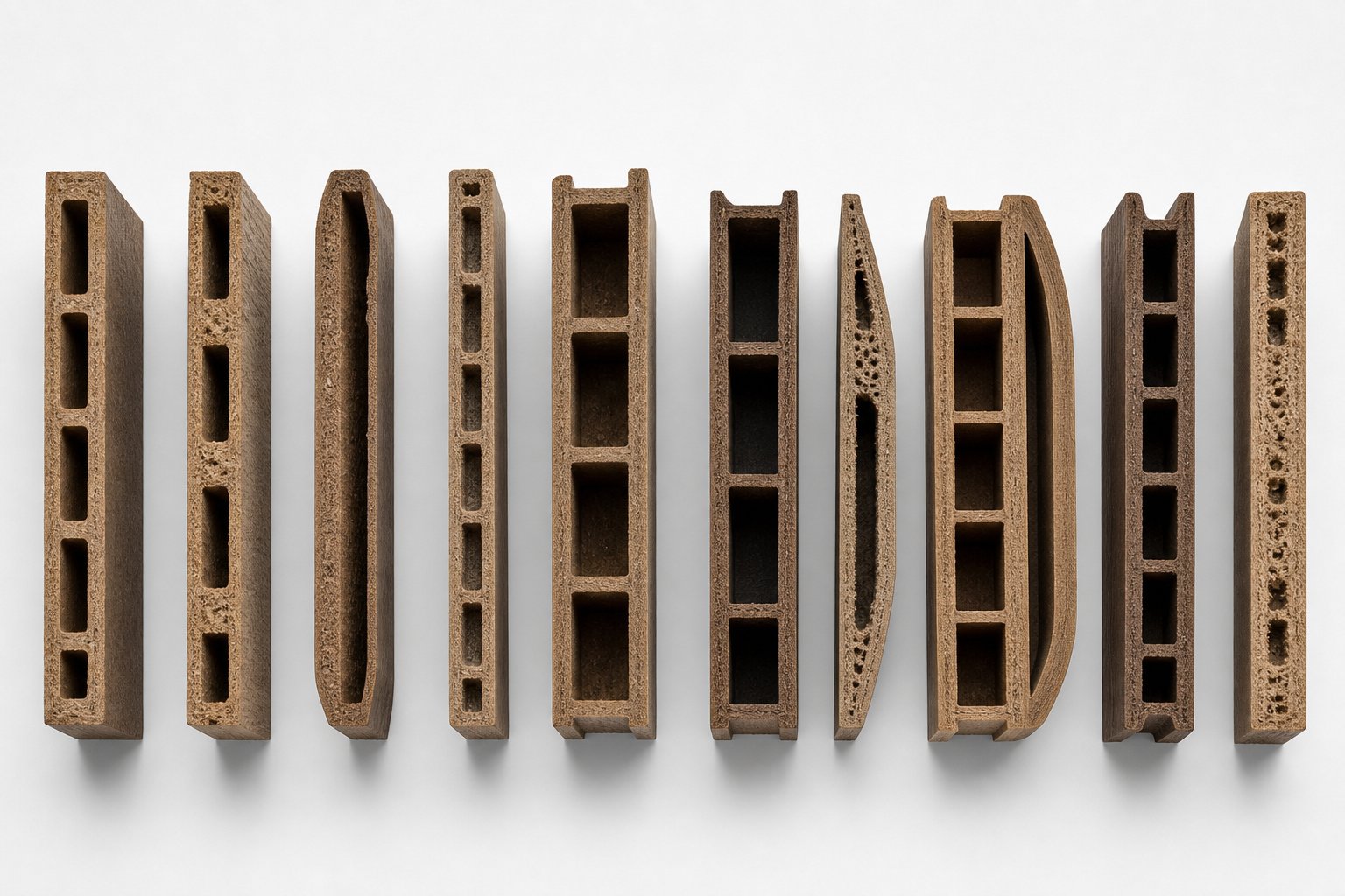
Every plastic wood composite formulation revolves around a single pivotal variable: how much wood versus how much plastic goes into the blend. Shift that ratio by ten percentage points in either direction and you change the stiffness, impact toughness, water absorption, raw material cost, and extruder torque demand all at once. Yet most production teams treat this ratio as fixed — inherited from a supplier data sheet rather than optimized for the specific application. Understanding what is composite wood made of at a given ratio, and what happens when you move that ratio, gives you a powerful lever for balancing cost against performance.
How Higher Wood Content Changes Mechanical Behavior
Imagine your formulation currently sits at 40% wood fiber by weight. The profiles extrude smoothly, the melt flows easily through the die, and impact resistance is decent. Your purchasing manager asks you to push wood content to 65% to cut resin costs. What changes?
The general principle is well established across peer-reviewed research: increasing wood fiber content from roughly 40% toward 70% drives stiffness upward while pulling impact resistance and processability downward. Wood fibers act as rigid fillers that restrict polymer chain mobility. More filler means a stiffer composite — flexural modulus climbs noticeably with each incremental increase in fiber loading. Studies on HDPE-based WPCs at 60% wood content report flexural strengths in the 67-74 MPa range and flexural modulus values between 3.8 and 5.8 GPa, depending on fiber size and distribution. Those numbers represent a substantial stiffness improvement over neat HDPE.
The trade-offs, however, are real and measurable:
- Impact resistance drops. As wood content rises, the polymer matrix — which absorbs energy during sudden loading — gets thinner between fiber particles. There is less plastic available to deform and dissipate energy before a crack propagates. Larger fiber sizes intensify this effect; research shows composites reinforced with coarse 10-20 mesh fibers exhibit impact strengths as low as 12.18 kJ/m², compared to 15.79 kJ/m² for finer 80-120 mesh fibers at the same 60% loading.
- Water absorption increases. Wood fibers are hydrophilic. The more fiber surface area exposed within the wood composite, the more pathways moisture finds to wick into the product. Higher wood loading also means more fiber-fiber contact points where the polymer matrix cannot fully encapsulate the cellulose — creating micro-channels for water ingress.
- Melt viscosity rises sharply. Rheological testing confirms that apparent viscosity increases rapidly with increasing fiber content, especially at low shear rates where fiber agglomerates resist untangling. This elevated viscosity demands more torque from the extruder drive, increases barrel pressure, and can push motor amperage toward its ceiling.
- Screw and barrel wear accelerates. More abrasive fiber particles flowing through tighter melt passages mean faster erosion of screw flights and barrel bore surfaces. The cost savings you gain from cheaper raw material can be offset by shorter maintenance intervals if your plasticizing components are not specified for high-wear duty.
Thermal behavior shifts too. Differential scanning calorimetry data shows that as wood fiber content rises from 50% to 70%, the melting temperature and crystallinity of the HDPE matrix both decrease while crystallization temperature increases. Practically, this means the polymer matrix becomes harder to melt uniformly and crystallizes earlier during cooling — a combination that narrows your processing window and demands more precise temperature zone control.
Finding the Optimal Ratio for Your Application
So what is wood composite at its best formulation point? That depends entirely on what the finished product needs to do.
For outdoor decking and cladding — the largest market segment for this material — most manufacturers target 50-60% wood content. This range delivers a favorable balance: enough fiber for cost-effective stiffness and a natural wood composite aesthetic, but enough polymer matrix to maintain acceptable impact resistance, limit water absorption, and keep the melt processable without extreme torque demands. WPC decking products in this range also retain sufficient polymer encapsulation around fibers to resist UV degradation and fungal attack with standard additive packages.
Indoor profiles and flooring applications often benefit from lower wood ratios — in the 30-45% range. Why? Indoor products face less UV and moisture stress but require higher impact performance to withstand foot traffic, furniture loads, and occasional dropped objects. Reducing wood content increases the volume of energy-absorbing polymer matrix available, boosting toughness without sacrificing the appearance benefits of the wood filler.
The polymer matrix choice also shifts your practical ceiling for wood loading. PE-based formulations handle high wood content more easily because HDPE's lower melt viscosity and broader processing window accommodate the viscosity spike that high fiber loading creates. Research on recycled HDPE composites found that dimensional stability plateaus at approximately 60% wood fiber — pushing beyond that threshold adds processing difficulty without meaningful property gains. PVC-based formulations, by contrast, already run in a tighter thermal window. Adding more wood fiber raises viscosity further and increases the risk of thermal degradation, so PVC-WPC products typically stay closer to 40-55% wood content.
| Property | Low Wood Content (30-40%) | Medium Wood Content (50-60%) | High Wood Content (65-70%) |
|---|---|---|---|
| Stiffness (Flexural Modulus) | Moderate | High | Very High |
| Impact Resistance | High | Moderate | Low |
| Water Absorption | Low | Moderate | High |
| Processability (Melt Flow Ease) | Easy — low viscosity, low torque | Manageable — moderate viscosity increase | Difficult — high viscosity, high torque, risk of degradation |
| Raw Material Cost | Higher — more polymer consumed | Balanced — cost-effective ratio | Lower — maximum resin displacement by fiber |
| Typical Applications | Indoor flooring, trim, furniture profiles | Decking, cladding, fencing, railing | Industrial boards, cost-driven structural profiles |
One additional nuance worth noting: fiber size distribution within a given ratio can unlock performance improvements that simply adjusting the overall wood percentage cannot. Experimental work on HDPE composites at 60% wood content demonstrated that blending 20-40 mesh and 40-80 mesh fibers together yielded the best flexural performance (strength of 74.16 MPa, modulus of 5.35 GPa), while a blend of all four fiber size fractions produced the highest impact strength (16.08 kJ/m²) — outperforming every single-size formulation tested. Smaller particles fill gaps between larger fibers, improving packing density and matrix penetration simultaneously.
The practical message? Don't treat wood-to-plastic ratio as a single number to lock in. Treat it as a tunable system — where the ratio, the particle size distribution, and the polymer type interact to define your performance envelope. Dialing in that system, however, means nothing if the extrusion process parameters — particularly temperature zone strategy, screw speed, and feed rate — are not calibrated to match.
Critical Process Parameters and Temperature Zones
Your formulation is locked, your extruder architecture is selected, and your wood-to-plastic ratio is optimized. Yet profiles still come out with rough surfaces, burn marks, or inconsistent dimensions. Why? Because the temperature profile, screw speed, and feed rate settings are the real-time dials that translate a good formulation into a good product — or ruin it entirely. Getting these parameters wrong by even 10-15 degrees in a single barrel zone can trigger thermal degradation of wood fibers, incomplete polymer fusion, or uncontrollable melt viscosity swings. This section gives you the zone-by-zone framework to set up each polymer type correctly.
Temperature Zone Strategy for PE-Based and PP-Based WPC
Every barrel in a wood plastic extrusion line is divided into distinct heating zones, and each zone has a specific job. Think of the temperature profile as a carefully staged ramp — not a flat plateau. Set every zone to the same temperature and you'll either undercook the feed end or overcook the discharge end.
Here is the logic behind each zone:
- Feed zone (140-160 °C): This zone preheats raw materials just enough to begin softening the polymer without fully melting it. Why keep it relatively cool? Premature melting at the feed throat creates a sticky polymer film that blocks incoming wood flour from entering the screw flights — a phenomenon called bridging. Experienced machine builders recommend starting at 140-160 °C to ensure consistent material flow into the barrel without feed blockages.
- Plasticizing/compression zone (170-190 °C): Here, the polymer matrix fully melts and begins to encapsulate the wood particles. The mechanical shear from the screw combines with barrel heat to create a homogeneous melt. Temperatures in this zone must be high enough for complete polymer fusion but low enough to protect the cellulose component. Thermogravimetric studies confirm that wood fiber degradation begins around 200-220 °C, with hemicellulose breaking down first in the 225-325 °C range and cellulose following at 300-400 °C. Staying below 200 °C in this zone is critical for preserving fiber integrity.
- Metering/homogenizing zone (180-190 °C): This zone stabilizes melt viscosity and ensures uniform composition before the material reaches the die. Keeping temperatures close to or slightly above the plasticizing zone prevents premature cooling while maintaining consistent pressure buildup.
- Die zone (185-200 °C): The die runs slightly hotter than the homogenizing zone to prevent the melt from cooling prematurely inside the die land, which would cause surface roughness or incomplete profile fill-out. However, exceeding 200 °C at the die risks carbonizing wood flour at the profile surface — producing the dark streaks and burn marks that operators dread.
PE-based plastic composite formulations generally process at the lower end of these ranges because HDPE melts fully by 130-170 °C and flows easily around wood particles. PP-based composite plastics require temperatures 10-20 °C higher across most zones because polypropylene's melting point sits around 160-170 °C and its melt viscosity remains higher at equivalent shear rates. That upward shift tightens the margin between adequate polymer fusion and wood fiber degradation — meaning PP-based WPC demands more precise zone control and more frequent thermocouple verification than PE-based systems.
Temperature Zones for PVC-Based WPC Extrusion
PVC introduces a fundamentally different thermal challenge. Unlike polyolefins, PVC is an amorphous polymer with no sharp melting point — it transitions gradually from a rigid state to a processable gel. More critically, PVC begins to release hydrochloric acid and degrade at temperatures only slightly above its processing range. That narrow window — typically 150-185 °C for PVC-based plastic composites — leaves very little room for error.
When you add wood fibers that themselves start degrading above 200 °C, you get two overlapping thermal ceilings. Push temperatures high enough to ensure complete gelation and you risk both PVC decomposition and wood carbonization simultaneously. This is precisely why conical twin-screw extruders dominate PVC-based WPC production. Their low-speed, high-torque operation generates minimal frictional heat, allowing the barrel heaters — rather than shear energy — to control melt temperature with much greater precision. The result is a more stable process with fewer thermal spikes.
Practical PVC-WPC temperature profiles generally run 10-20 °C lower than PE-based equivalents across all zones. The feed zone stays at 130-150 °C to gently pre-heat the dry blend, the plasticizing zone targets 160-175 °C for controlled gelation, and the die stays at 170-185 °C. Even small thermocouple inaccuracies of 5-10 °C can push localized melt temperatures into the degradation range, so regular calibration of temperature sensors and inspection of barrel heating and cooling elements is essential for PVC-based lines.
Screw Speed, Throughput, and Feed Rate Balancing
Temperature profiles get most of the attention during setup, but screw speed and feed rate are just as important for stable wood plastic extrusion. Here is why: screw RPM controls three things simultaneously — throughput, residence time, and shear heating. Crank the speed too high and you shorten residence time (good for throughput) but generate excessive frictional heat (bad for wood fibers) and reduce mixing quality (bad for homogeneity). Drop it too low and residence time stretches out, exposing the melt to sustained heat that degrades both the polymer and the cellulose.
The key principle is matching feed rate to screw speed so the barrel stays consistently full without becoming overpacked. An overfed barrel spikes die pressure and motor amperage, causing surging — a rhythmic pulsation in the extrudate that produces visible thickness variations in the finished profile. An underfed barrel drops pressure unpredictably, creating voids and inconsistent density.
For PE- and PP-based WPC on co-rotating parallel twin screws, screw speeds typically range from 100-400 RPM during compounding, with the exact speed adjusted based on formulation viscosity and target throughput. For conical twin-screw extruders processing PVC-based or direct-extruded PE-based plastic composites, operating speeds are much lower — often 15-45 RPM — because the tapered screw geometry generates adequate pressure at low rotational speeds without the excessive shear that high RPM would produce.
One practical rule worth remembering: if you increase wood fiber content in your formulation, you almost always need to reduce screw speed slightly and adjust feed rate downward to compensate for the higher melt viscosity. Failing to make that adjustment forces the drive motor to work harder, accelerates wear on plasticizing components, and increases the risk of localized hot spots where fiber thermal degradation begins.
| Parameter | PE-Based WPC | PP-Based WPC | PVC-Based WPC |
|---|---|---|---|
| Feed Zone Temperature | 140-160 °C | 150-170 °C | 130-150 °C |
| Compression/Plasticizing Zone Temperature | 170-190 °C | 180-200 °C | 160-175 °C |
| Metering/Homogenizing Zone Temperature | 180-190 °C | 185-195 °C | 165-180 °C |
| Die Zone Temperature | 185-200 °C | 190-205 °C | 170-185 °C |
| Screw Speed Range (Twin-Screw Compounding) | 100-400 RPM | 100-350 RPM | 15-45 RPM (conical twin-screw) |
| Maximum Barrel Temperature Ceiling | ~200 °C (wood degradation limit) | ~205 °C (balance PP melt vs. fiber integrity) | ~185 °C (PVC degradation + wood degradation overlap) |
| Thermal Sensitivity | Moderate — widest processing window | Moderate to high — narrower margin above PP melt point | High — narrowest window, tightest control required |
These ranges represent general industry-accepted starting points. Every production line requires fine-tuning based on specific formulation loading, extruder geometry, die design, and ambient conditions. The safest approach is to start at the lower end of each range during initial setup, then incrementally raise temperatures zone by zone while monitoring melt quality, die pressure, and motor amperage. When those three indicators stabilize — and the extrudate surface looks clean, uniform, and free of discoloration — you have found your operating window.
Even a perfectly dialed-in temperature profile, however, cannot protect you from defects caused by upstream problems like residual moisture, worn barrel clearances, or inadequate fiber dispersion. Recognizing those defects when they appear — and tracing them back to their root causes — is the next critical skill every production engineer needs.
Troubleshooting Common WPC Extrusion Defects
You've set your temperature zones, balanced your screw speed, and confirmed your formulation ratio — yet the extrudate coming off the line still looks wrong. Maybe the surface is rough and rippled. Maybe the profile bows after cutting. Maybe you see dark streaks where there should be uniform color. Defects in composite plastic wood extrusion rarely announce their root cause on the surface. They force you to work backward — from visible symptom to hidden mechanism — and that detective work is where most production teams lose time and material.
This section gives you a structured troubleshooting framework covering both surface and internal defects, written so a process technician standing at the line can diagnose and correct issues without guesswork.
Surface Defects and Their Root Causes
Surface quality is the first thing an operator notices, and it is often the first thing a customer rejects. Four defect categories account for the vast majority of surface-related problems on solid plastic composite profiles.
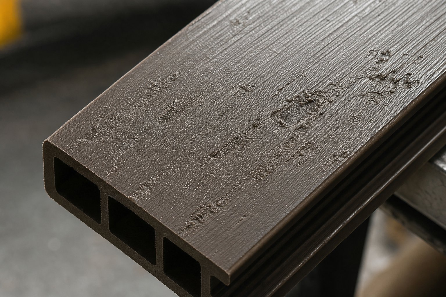
Melt fracture appears as a wavy, sharkskin-like texture or irregular streaks across the profile surface. The mechanism is straightforward: the melt encounters excessive shear stress as it passes through the die land, and the elastic component of the polymer melt causes the extrudate surface to rupture rather than flow smoothly. In WPC, high wood fiber loading raises melt viscosity dramatically, pushing shear stress at the die wall beyond the critical threshold for fracture. Corrective actions include reducing extrusion speed, raising die zone temperature slightly to lower melt viscosity, widening the die gap to decrease wall shear rate, and — critically — verifying that your lubricant levels are adequate. Adding processing aids or external lubricants like zinc stearate directly reduces friction between the melt and die surface.
Surface roughness differs from melt fracture in that the texture is uniformly gritty rather than wavy. You'll feel it when you run your hand across the profile — it catches rather than glides. The usual culprits are insufficient melt temperature (the polymer hasn't fully encapsulated the wood particles at the surface), inadequate internal lubricant concentration, or an excessively coarse wood flour fraction that pokes through the skin layer. Raising the die zone temperature by 5-10 °C, increasing lubricant dosage, or shifting to a finer mesh fiber fraction typically resolves the issue.
Discoloration and burn marks show up as dark brown or black streaks, patches, or an overall yellowing of the profile. The root cause is thermal degradation — either the wood fibers, the polymer, or both have been exposed to excessive heat or excessive residence time inside the barrel. Remember, wood fibers begin degrading above approximately 200 °C, and PVC starts releasing hydrochloric acid in a similar temperature range. Burn marks concentrated near the edges of the profile often indicate dead spots in the die where material stagnates and cooks. Corrective actions include lowering barrel and die temperatures, reducing screw speed to decrease frictional heat, streamlining the die flow channel to eliminate stagnation zones, and purging the barrel to remove any carbonized residue that may be contaminating fresh material.
Poor fiber dispersion is immediately visible as light-colored wood clumps or fiber bundles embedded in the profile surface. You're looking at raw wood flour that never got properly wetted by the polymer melt — essentially islands of dry cellulose in a plastic sea. This defect points directly to inadequate mixing intensity. On single-screw lines running pre-compounded pellets, it may indicate that the upstream compounding step was too short or too gentle. On twin-screw direct extrusion lines, it signals that the screw configuration needs more kneading block elements or that the screw speed is too low relative to feed rate to generate sufficient dispersive mixing.
Internal Defects and Dimensional Problems
Internal defects are more insidious than surface issues because they can hide inside an otherwise good-looking profile and only reveal themselves during mechanical testing, installation, or field use. Four categories dominate WPC processing.
Voids and porosity are the most common internal defect in comp wood extrusion, and the primary culprit is almost always moisture. Wood fiber that enters the barrel above 1-2% moisture content will release steam as the melt temperature climbs past 100 °C. That steam creates internal bubbles that freeze in place as the profile cools. Cut a cross-section and you'll see a constellation of small holes where structural material should be. Effective moisture removal through proper pre-drying — and verifying moisture levels before every production run — is the only reliable prevention. Vacuum venting ports in the barrel can also extract residual moisture and volatiles during processing.
Die swell causes the extrudate to expand beyond the die dimensions immediately after exiting. The polymer melt retains elastic memory from the shear and compression it experienced inside the barrel, and once the constraining die walls disappear, that stored energy pushes the profile outward. In WPC, higher polymer content and higher extrusion speeds increase die swell. Reducing screw speed, lowering die temperature slightly, or increasing the length of the die land to allow more stress relaxation before exit are practical corrections.
Warping during cooling produces profiles that twist, bow, or curve rather than lying flat. The mechanism is uneven cooling: one side of the profile solidifies and shrinks faster than the other, creating residual stresses that pull the shape out of true. This is especially problematic in thicker plastic on wood profiles where the core takes significantly longer to cool than the skin. Uniform cooling — whether through symmetrically positioned spray nozzles, balanced water bath flow, or calibrated air cooling — is the solution. Slowing the puller speed to increase cooling time also helps, though it reduces throughput.
Inconsistent wall thickness reveals itself as dimensional variations across the profile cross-section — one side thicker than the other, or random thin spots that create structural weak points. Two root causes are most common: worn screw and barrel clearances that allow uneven melt flow, and die flow imbalances where the melt takes the path of least resistance rather than filling the die cavity uniformly. Checking flight clearances and die pin alignment addresses the mechanical causes; adjusting choke bars or flow restrictors within the die corrects flow distribution problems.
| Defect Type | Visual Symptom | Primary Root Cause | Corrective Action |
|---|---|---|---|
| Melt Fracture | Wavy, sharkskin-like surface texture or irregular streaks | Excessive shear stress at die wall due to high melt viscosity | Reduce extrusion speed; raise die temperature 5-10 °C; increase lubricant dosage; widen die gap |
| Surface Roughness | Uniformly gritty, sandpaper-like texture across profile | Insufficient melt temperature or lubricant; coarse fiber fraction protruding through surface | Raise die zone temperature; increase internal lubricant; shift to finer mesh wood flour |
| Discoloration / Burn Marks | Dark brown or black streaks, patches, or overall yellowing | Thermal degradation from excessive temperature, residence time, or die stagnation zones | Lower barrel/die temperatures; reduce screw speed; streamline die flow channels; purge barrel |
| Poor Fiber Dispersion | Visible light-colored wood clumps or fiber bundles on surface | Inadequate mixing intensity — fiber not fully wetted by polymer melt | Add kneading blocks to screw configuration; increase screw speed; verify upstream compounding quality |
| Voids / Porosity | Internal bubbles or holes visible in cut cross-section | Moisture in wood fiber flashing to steam during processing | Verify fiber moisture is below 1-2% before feeding; add vacuum venting ports; improve pre-drying process |
| Die Swell | Profile dimensions exceed die opening size after exit | Elastic memory in polymer melt releasing after die constraint is removed | Reduce screw speed; lower die temperature slightly; increase die land length for stress relaxation |
| Warping / Bowing | Profile twists, curves, or bows instead of lying flat | Uneven cooling rates creating asymmetric residual stresses | Ensure symmetric cooling setup; balance water bath flow or spray nozzle positioning; reduce puller speed |
| Inconsistent Wall Thickness | Dimensional variation across cross-section — thick and thin spots | Worn screw/barrel clearances causing uneven melt delivery; die flow imbalance | Check and replace worn screws/barrels; adjust die choke bars or flow restrictors; verify die pin alignment |
When to Suspect Equipment Wear
Some defects arrive suddenly — a moisture spike from a bad batch of fiber, a thermocouple failure in zone three. Others creep in so gradually that operators adapt without realizing the process has drifted. That slow drift is the signature of screw and barrel wear, and it deserves special attention in WPC processing.
Abrasive wood flour particles, especially when combined with mineral fillers like talc or calcium carbonate, erode screw flight tips and barrel bore surfaces at rates far beyond what standard unfilled polymer processing produces. Industry experts note that as flight clearances widen, the processor must increase screw speed to maintain the same output rate — and that higher speed further raises discharge temperatures, compounding the problem. At some point, the rate reduction and temperature rise make the line uneconomical.
Here are the warning signs to watch for:
- Rising screw torque at constant RPM: The motor works harder because material leaks backward over worn flights instead of being conveyed forward efficiently.
- Declining specific rate: You need more screw revolutions to push the same kilograms per hour through the die — a direct indicator that conveying efficiency has dropped.
- Higher discharge temperatures: Worn clearances increase the melt film thickness at the barrel wall, reducing heat transfer efficiency and causing temperature to climb even without any change in heater settings.
- Increasing output variation: Subtle fluctuations in extrudate dimensions, weight per meter, or surface quality that worsen week over week point to progressively uneven melt delivery.
- Visible scoring on pulled screws: During scheduled maintenance, inspect the screw flights for grooves, thinning of hard-facing material, or polished wear patterns. A screw should generally not be refurbished more than three times, as repeated welding of new hard facing degrades the base metal and increases the risk of delamination.
The practical guideline many processors follow is to replace or recondition the screw when flight clearance reaches approximately four times the original clearance — though critical-duty applications may require action much sooner. Keeping a spare screw on hand minimizes downtime; the worn screw can be sent for refurbishment while production continues with the replacement.
Barrel wear follows the same trajectory but progresses more slowly. Iron-based bimetallic barrel liners typically last through the service life of about three screws. Measuring the barrel bore diameter during every screw change gives you a trend line that predicts when the barrel itself needs replacement — before it starts producing the dimensional inconsistencies and melt quality problems that no amount of process adjustment can fix.
Defect-free profiles emerging from a healthy extruder are still only raw shapes. Transforming them into the finished decking boards, cladding planks, and flooring products that customers actually buy requires a series of downstream operations — calibration, cooling, embossing, and surface finishing — each with its own set of technical considerations.
Post-Extrusion Operations and Surface Finishing
A raw extrudate emerging from the die is not a product anyone can sell. It is a hot, slightly oversized shape that still needs to be cooled to dimensional tolerance, textured for visual appeal, and cut to length. These downstream operations determine whether your wood plastic composite decking boards, cladding planks, or flooring profiles look and perform like premium building materials — or get rejected at quality inspection. Yet most technical discussions of the extrusion process stop at the die exit, leaving production teams to figure out calibration, cooling, and finishing through trial and error.
Calibration, Cooling, and Dimensional Control
The moment the melt leaves the die, it begins to cool, shrink, and — if uncontrolled — distort. Calibration equipment forces the still-soft extrudate into precise dimensional conformity before it solidifies, and the cooling method you choose directly influences both the internal structure and the throughput of your line.
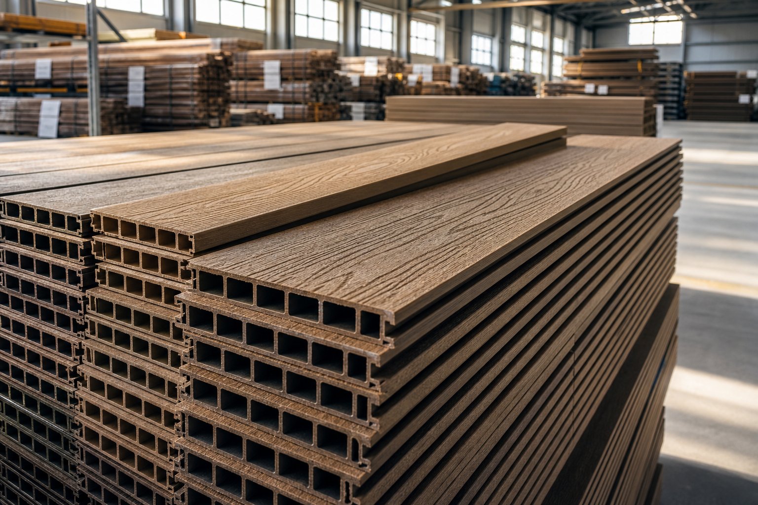
Vacuum calibration tanks are the standard for hollow and semi-hollow WPC profiles. The extrudate enters a water-filled sizing sleeve connected to a vacuum pump. Negative pressure pulls the softened profile walls outward against the calibrator surfaces, locking in the cross-sectional geometry while the water simultaneously extracts heat. For solid composite board or plastic board profiles like decking planks, vacuum calibration may be simplified to a dry sizing plate followed by a separate cooling stage — but the principle remains the same: shape first, then solidify.
Three cooling methods serve different production needs:
- Water bath cooling: The profile passes through a tank of temperature-controlled water. This delivers the fastest, most uniform heat extraction and is the default choice for thick plastic planks and decking boards. Water temperature is typically held at 15-25 °C — cold enough for efficient cooling but not so cold that it creates thermal shock at the profile surface.
- Spray cooling: Fine water jets directed at the profile surface offer more precise control over where and how fast cooling occurs. Spray systems are particularly useful for asymmetric profiles or situations where one surface needs faster cooling than another to prevent warping.
- Air cooling: Forced air or ambient convection is the gentlest method, used primarily for thin-walled profiles or foam-core products where aggressive water contact could cause surface blistering. Air cooling is slower, which means longer cooling sections and reduced line speed.
Why does cooling rate matter beyond simple throughput? In PE-based WPC, the cooling rate directly affects the crystallinity of the polyethylene matrix. Slow cooling allows more crystalline regions to form, increasing stiffness and chemical resistance but also slightly increasing shrinkage. Rapid cooling produces a more amorphous matrix — slightly more flexible and dimensionally stable in the short term, but with potentially lower long-term creep resistance. In PVC-based WPC, cooling rate primarily affects residual internal stress. Cool a PVC profile too aggressively and the frozen-in stresses can cause delayed warping or cracking days or weeks after production, particularly in warmer storage environments.
The practical balancing act is straightforward: cool as fast as you can without introducing warping, internal stress, or surface defects — then adjust puller speed to match. If profiles are bowing after cutting, your cooling is either too aggressive, too uneven, or too short. If your line speed is bottlenecked by cooling capacity, adding a second cooling tank or switching from air to spray cooling can recover throughput without changing any upstream parameters.
Surface Finishing and Embossing for Realistic Aesthetics
Ever wondered how to make plastic look like wood? The answer lives in the finishing stations downstream of the cooling tanks. Raw extruded WPC profiles have a smooth, somewhat artificial surface that reveals their composite origin. Transforming that surface into something that genuinely resembles natural timber grain requires one or more finishing techniques — and the choice between them determines both the visual quality and the manufacturing cost of the final product.
Hot-die embossing is the most common method for creating deep wood-grain textures on wood plastic composite decking and cladding. A heated steel roller or plate with an engraved wood-grain pattern presses into the still-warm profile surface immediately after calibration. The heat softens the surface layer just enough for the pattern to transfer cleanly, and the texture locks in as the material cools. The result is a tactile, three-dimensional grain that mimics sawn or brushed timber — the primary reason plastic that looks like wood has become commercially viable for high-end outdoor applications. Pattern designs range from subtle wire-brushed textures to deep cathedral grain, and manufacturers often run multiple embossing rollers to offer product variety from the same base profile.
Brushing and sanding create a more subtle, matte finish by mechanically abrading the profile surface. Wire brushes pull across the cooled extrudate to expose the embedded wood fibers, producing a natural look and soft hand-feel that many consumers prefer over high-gloss finishes. Sanding with progressively finer grits refines the surface further and improves paint or stain adhesion for products that receive a secondary coating. These operations are typically inline — the profile passes through brushing heads at line speed without stopping.
Co-extrusion with a capstock layer represents the most significant advancement in WPC surface technology. Instead of finishing the surface after extrusion, co-extrusion applies a thin, engineered polymer cap — often an ASA (acrylonitrile styrene acrylate) or modified HDPE blend — directly onto the composite board core during the extrusion process itself. This cap layer is permanently fused to the substrate, not painted or glued on, which means it cannot peel or delaminate under normal use. The capstock provides enhanced UV resistance, superior color consistency, and improved stain and scratch resistance — properties that second-generation co-extruded WPC products leverage for warranties of 20-25 years in outdoor applications. For production engineers, co-extrusion requires a secondary extruder and a specialized die head that merges the cap melt with the core melt, adding capital cost but delivering a significantly higher-value product.
Foamed WPC core technology adds another dimension to composite board design. By introducing a chemical or physical foaming agent into the core formulation, manufacturers reduce the density of the interior while maintaining a solid skin. The result is a lighter plastic board that uses less raw material per linear meter — an important cost and handling advantage for wood plastic composite flooring and wide-format cladding panels. Foamed cores also improve thermal and acoustic insulation properties. The solid outer skin, whether embossed or co-extruded, provides the structural surface and visual appearance while the foamed interior carries the load at reduced weight.
The complete downstream sequence for a typical WPC production line follows a predictable order, with each station adding one layer of dimensional control or aesthetic value:
- Sizing and calibration: Vacuum calibration tables or dry sizing plates lock in the profile cross-section while the material is still soft.
- Cooling: Water bath, spray, or air cooling solidifies the profile and stabilizes its dimensions.
- Embossing: Heated rollers or plates impress wood-grain patterns into the profile surface.
- Brushing and sanding: Mechanical surface treatment exposes wood fibers and creates a natural matte texture.
- Cutting: Flying saws or rotary cutters trim profiles to specified lengths without stopping the line.
- Stacking and packaging: Finished profiles are automatically stacked, banded, and wrapped for shipping or warehouse storage.
These operations are what ultimately transform continuous extrudate into the specific products end users purchase — wood plastic composite decking boards for residential patios, wood plastic composite flooring planks for commercial interiors, cladding profiles for building facades, and fencing components for property boundaries. Each product category demands its own combination of finishing steps, and the line layout should reflect those requirements. A decking line, for example, might prioritize deep embossing and co-extrusion for outdoor durability, while a flooring line may emphasize precision sanding and tight dimensional tolerances for click-lock installation systems.
Producing plastic that looks like wood at industrial scale is ultimately a matter of coordinating every upstream decision — formulation, fiber preparation, extrusion parameters — with these downstream finishing steps. The best embossing station in the world cannot rescue a profile with internal voids or poor fiber dispersion. Equally, a perfectly extruded profile shipped with a bland, untextured surface fails to compete in a market that demands natural aesthetics. Getting the full chain right, from raw fiber to flawless finish, is what separates commodity producers from premium WPC manufacturers — and doing so sustainably, with recycled feedstocks and efficient equipment, is where the industry is heading next.
Sustainability and Production Line Reliability
Premium surface finishes and tight dimensional tolerances attract customers, but increasingly those same customers want to know what the product is made from and where those materials end up at end of life. The environmental story behind wood plastic composite extrusion is genuinely compelling — yet most manufacturers tell it poorly or not at all. Connecting sustainability credentials to practical production decisions turns environmental responsibility from a marketing slogan into a measurable competitive advantage.
Environmental Advantages and Recycled Feedstock Integration
Every WPC profile you extrude diverts two waste streams from landfills simultaneously. The wood fiber fraction — sawdust, planer shavings, offcuts — originates from post-industrial wood processing residues that would otherwise be burned or buried. The polymer fraction can come entirely from post-consumer recycled plastics, primarily HDPE recovered from milk jugs, detergent bottles, and industrial packaging. Together, these recycled inputs displace virgin petroleum-based resin and reduce demand on managed forests, creating a product that is essentially recycled plastic wood engineered for decades of outdoor service.
The lifecycle math favors WPC over treated lumber by a wide margin. Pressure-treated softwood decking typically requires staining or sealing every two to three years, and even with maintenance it may need replacement within 10-15 years as rot, insect damage, and UV degradation take their toll. A well-formulated WPC deck board lasts 25-30 years with minimal maintenance — no staining, no sealing, no chemical preservative treatments leaching into surrounding soil. That extended service life amortizes the embodied energy of manufacturing across a much longer useful period. Research on WPC lifecycle performance notes that the climate impact balance becomes increasingly positive the longer the product remains in service, because the wood fibers sequestered carbon during their growth that equals or exceeds the energy consumed during production.
At end of life, WPC products can be re-ground and re-extruded into new profiles — a closed-loop recycling pathway that pure lumber cannot match. Plastic lumber recycling infrastructure is still developing at industrial scale, but the technical feasibility is well established. Ground WPC regrind blends back into fresh formulations at 10-30% loading without significant property loss, especially when supplemented with virgin coupling agents to restore fiber-matrix adhesion.
Emerging feedstock innovations are pushing the sustainability envelope further. Some manufacturers now incorporate post-consumer ocean plastics into their polymer matrix, turning marine pollution into durable recycled plastic timber for boardwalks and waterfront installations. Bio-based polymers like PLA (polylactic acid) are also being explored as matrix materials, though JRC policy research highlights that bio-based plastics still face significant cost and technology readiness barriers — production costs remain roughly 1.5 to 2 times higher than fossil-based alternatives, and global bio-based plastic capacity accounts for only about 0.5% of total plastics production. For now, recycled HDPE and PP remain the most practical and cost-effective sustainable matrix options for commercial WPC extrusion.
The sustainability case extends beyond raw materials. Products like recycled plastic logs for landscaping borders, plastic recycled wood fencing, and composite cladding panels all replace chemically treated lumber in applications where rot resistance, dimensional stability, and zero-maintenance performance matter most. Each installation that chooses WPC over virgin timber is one less demand signal for harvested old-growth or plantation softwood — and one more demonstration that recycled feedstocks can deliver professional-grade performance.
Building a Reliable and Efficient WPC Production Line
Sustainability goals only deliver value if the production line behind them runs reliably. And reliability in WPC manufacturing is not a single equipment decision — it is the cumulative result of every formulation and equipment choice cascading through the entire process chain.
Consider how a single variable — wood-to-plastic ratio — ripples across the entire operation. Increasing wood content from 50% to 65% reduces polymer cost per kilogram of output, which looks attractive on a purchasing spreadsheet. But that same change raises melt viscosity, increases extruder torque demand, shortens screw and barrel service life due to accelerated abrasive wear, and may require slower line speeds to avoid thermal degradation. The polymer savings can be partially or fully offset by higher energy consumption, more frequent maintenance shutdowns, and increased scrap rates if the process window narrows beyond what the equipment can hold consistently.
Polymer choice creates a parallel cascade. Switching from HDPE to PVC changes your processing temperature window, your additive package, your extruder architecture requirements, and your downstream cooling strategy. A line designed around PE-based formulations cannot simply swap to PVC compounds without reconsidering screw geometry, barrel metallurgy, and temperature control precision.
Throughput, energy consumption, and material cost balance are all interconnected in ways that reward systems-level thinking over isolated optimizations. The most efficient WPC production lines are those where:
- Formulation is matched to equipment capability: The wood fiber loading, polymer type, and additive package are specified within the mixing, shear, and thermal limits of the installed extruder architecture.
- Fiber preparation is consistent: Particle size distribution and moisture content arrive at the hopper within tight tolerances, eliminating the process variability that forces operators into constant reactive adjustments.
- Plasticizing components are specified for the formulation: Screw and barrel materials, coatings, and geometries are chosen based on the abrasiveness and thermal demands of the actual compound being run — not based on generic catalog recommendations for unfilled polymers.
- Preventive maintenance follows wear trends: Screw flight clearance, barrel bore diameter, and motor amperage are tracked over time, and component replacement happens before performance degrades to the point of producing scrap.
That last point deserves emphasis. Consistent plasticizing performance is the foundation of output stability in any extrusion operation, and it depends entirely on maintaining the mechanical precision of the screw and barrel system. In WPC processing — where abrasive wood fibers and mineral fillers erode flight tips and barrel liners far faster than unfilled polymer compounds — proactive component management is not optional. It is the difference between a line that holds tolerance for 8,000 hours and one that drifts into scrap production after 3,000.
For WPC manufacturers running conical twin-screw extruders — particularly those processing PVC-based formulations where the thermal processing window is narrowest — maintaining production reliability means sourcing wear-resistant conical twin screw barrels designed specifically for the abrasive demands of wood-filled compounds. NANHAIYA's conical twin screw barrel solutions offer custom and replacement barrels engineered for stable output, wear resistance, and consistent plasticizing performance in WPC and PVC extrusion applications — a specialist resource worth evaluating when your maintenance data signals that existing components are approaching the end of their effective service life.
Wood plastic composite extrusion sits at a productive intersection: it converts waste materials into durable, low-maintenance products through a manufacturing process that rewards precision engineering at every stage. From fiber preparation through compounding, extrusion, and finishing, every decision in the chain either builds reliability or erodes it. The producers who thrive long-term are those who treat the entire system — raw materials, formulation science, extruder architecture, process parameters, and component maintenance — as a single integrated machine, tuned to deliver both sustainable products and sustainable profitability.
Frequently Asked Questions About Wood Plastic Composite Extrusion
1. What does WPC stand for and how is it manufactured?
WPC stands for Wood Plastic Composite, a hybrid material that blends wood fibers or flour with a thermoplastic polymer such as HDPE, PP, or PVC. It is manufactured primarily through extrusion, where dried wood particles are melt-blended with the polymer matrix and functional additives inside a heated extruder, then forced through a shaped die to form continuous solid or hollow profiles. The extrusion method is favored because it produces consistent cross-sections at high throughput, making it ideal for decking, cladding, fencing, and flooring products.
2. What is the best wood-to-plastic ratio for WPC decking?
Most WPC decking manufacturers target 50-60% wood fiber content by weight. This range balances stiffness and a natural wood aesthetic with adequate impact resistance, manageable water absorption, and stable processability. Going below 50% increases polymer cost without meaningful stiffness gains for outdoor use, while exceeding 60% raises melt viscosity, accelerates screw and barrel wear, and increases moisture uptake. The optimal ratio also depends on the polymer matrix: PE-based formulations tolerate higher wood loading more easily than PVC-based systems, which typically stay closer to 40-55% fiber content.
3. Why do WPC extruded profiles get burn marks or surface defects?
Burn marks and discoloration in WPC extrusion result from thermal degradation of wood fibers or the polymer matrix caused by excessive barrel or die temperatures, prolonged residence time, or stagnation zones inside the die. Wood fibers begin degrading above approximately 200 degrees Celsius, releasing volatiles that carbonize on the profile surface. Other common surface defects include melt fracture from excessive die shear stress, surface roughness from insufficient melt temperature or lubricant levels, and visible fiber clumps from inadequate mixing intensity. Each defect traces to a specific root cause and can be corrected by adjusting temperature, screw speed, lubricant dosage, or screw configuration.
4. Which extruder type is best for WPC production?
The best extruder depends on your polymer matrix and process strategy. Co-rotating parallel twin-screw extruders excel at compounding and pelletizing WPC blends thanks to their aggressive mixing capability and modular screw design. Counter-rotating conical twin-screw extruders are ideal for PVC-based WPC and direct extrusion because their low-speed, high-torque operation generates minimal shear heat, protecting heat-sensitive materials. Single-screw extruders work well as downstream profile shapers when fed pre-compounded WPC pellets. For conical twin-screw lines, sourcing wear-resistant barrels from specialists like NANHAIYA helps maintain consistent plasticizing performance under the abrasive conditions of wood-filled compounds.
5. How does moisture in wood fiber affect WPC extrusion quality?
Moisture is one of the most damaging variables in WPC extrusion. Wood fiber moisture content must be reduced below 1-2% before processing. Any residual water trapped in the polymer melt flashes into steam at extrusion temperatures, creating internal voids, surface blisters, and structural porosity that compromise both appearance and mechanical integrity. Effective pre-drying using rotary drum dryers, flash dryers, or oven systems is essential, and moisture levels should be verified before every production run. Vacuum venting ports in the extruder barrel can also extract residual moisture and volatiles during processing as a secondary safeguard.
Written by
Nanhaiya Technical Team
Zhoushan Nanhaiya Plastic Machinery Co., Ltd.
The Nanhaiya technical team supports screw and barrel manufacturing projects through application review, technical communication, custom manufacturing coordination, and production and quality control.
Discuss Your Application
Related Articles
More insights on screw barrel technology and plastics processing.

What Nobody Tells You About Screw Barrel For Plastic Machine Design
Oct 10, 2026
Learn how screw barrel for plastic machine design affects melt quality, throughput, and wear life. Covers geometry, resin matching, troubleshooting, and sourcing.
Read Article
Single Screw Extruder for Sheet: Stop Guessing, Start Specifying
Oct 9, 2026
Learn how to specify a single screw extruder for sheet production. Covers screw geometry, resin-specific processing, troubleshooting, and maintenance best practices.
Read Article
PE Pipe Extruder Machine: What Datasheets Won't Tell You
Oct 9, 2026
Learn how a PE pipe extruder machine works, key specs explained, material grade selection, maintenance tips, and buyer guidance beyond the datasheet.
Read ArticleLooking for something else?
Search by material, symptom or product and jump straight to the relevant page.
These are navigation suggestions based on keyword matching — not a quotation, not a delivery commitment, and not a substitute for engineering review. Final specification is confirmed by our engineers against your drawings and processed material.
Need help with screw barrel selection?
Share your machine model, processed material and application. Our team can help with pricing and technical support.