

What Is a Twin Screw Extruder and How Does It Work
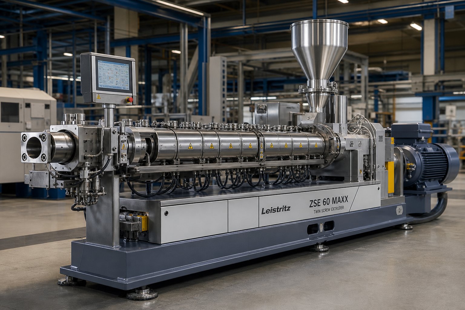
A twin screw extruder is a machine that uses two intermeshing screws rotating inside a heated barrel to convey, melt, mix, and shape materials. It serves as the backbone of modern polymer compounding, reactive extrusion, and advanced material processing across industries ranging from plastics to pharmaceuticals. But what exactly makes this machine so versatile, and why does the presence of a second screw change everything?
Defining the Twin Screw Extruder
At its core, a twin-screw extruder combines two precisely engineered screws within a single figure-eight-shaped barrel. A motor and gearbox supply rotational power, while heaters mounted along the barrel provide thermal energy. Together, these mechanical and thermal inputs transform raw materials — pellets, powders, fibers, or liquids — into a homogeneous melt that can be shaped at the die exit.
A twin screw extruder is a processing machine in which two intermeshing screws rotate within a closed barrel, applying controlled mechanical shear and thermal energy to convey, melt, mix, and shape polymers and other materials with high precision and consistency.
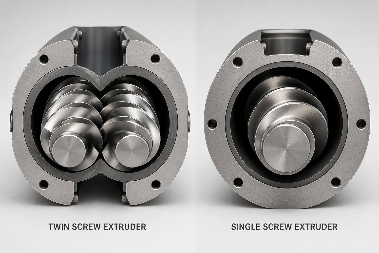
What separates this machine from simpler extrusion equipment is not just the extra screw. It is the way those twin screws interact. In a single screw design, material transport depends heavily on friction and viscous drag against the barrel wall, which leads to a broad residence time distribution and limited mixing. A twin screw extruder, by contrast, relies on positive displacement conveying — the intermeshing screw flights trap material in discrete pockets and push it forward with each rotation, regardless of the material's viscosity or flow characteristics. This fundamental difference gives operators far greater control over throughput, mixing intensity, and product uniformity.
Fundamental Working Principle
Imagine two gears rotating side by side, their teeth always in contact. The twin screws inside the barrel behave in a remarkably similar way. As one screw flight passes over the other, it scrapes material off the neighboring screw's surface and transfers it across the intermeshing zone. This continuous hand-off creates a distinctive figure-eight flow path — material advances in an "∞" shape, moving from one screw to the other as it travels down the barrel length.
This intermeshing geometry produces what engineers call a self-wiping action. Because the screw flights closely engage with one another, they automatically scrape away any material that might otherwise stick to the screw surfaces or barrel wall. The result? Material stagnation is virtually eliminated, and every particle spends a similar amount of time inside the machine. In technical terms, the residence time distribution is narrow and uniform — a critical factor when you need consistent product quality batch after batch.
The self-wiping mechanism is also what makes co-rotating twin screw extruders particularly effective for compounding applications. In a co-rotating configuration, both screws turn in the same direction, and the relative velocity at the intermeshing zone is high. This generates strong shear forces that break down agglomerates, disperse fillers, and blend multiple components into a truly homogeneous mixture. At the same time, the wiping effect prevents material from lingering in dead zones where it could overheat, degrade, or form gels that compromise the final product.
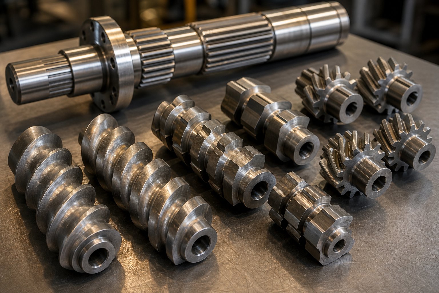
The extruder screw profile itself is modular — individual elements slide onto a splined shaft and can be rearranged to create distinct processing zones along the barrel. Conveying elements move material forward, kneading blocks apply intense shear for melting and dispersive mixing, and reverse elements build pressure or create melt seals. This modularity means a single machine can be reconfigured to process everything from glass-fiber-reinforced nylon to sensitive biodegradable polymers, simply by swapping and rearranging screw elements.
This interplay between positive displacement conveying, self-wiping behavior, and modular design is what gives the twin screw extruder its extraordinary versatility. Yet the real magic happens when you understand how each processing zone — feeding, melting, mixing, devolatilization, and shaping — works together as a coordinated sequence.
The Complete Twin Screw Extrusion Process Step by Step
Every finished pellet, film, or profile starts as a pile of raw ingredients — pellets, powders, liquids, and additives that need to be transformed into a uniform product. The twin screw extrusion process accomplishes this transformation through a carefully orchestrated series of zones, each performing a distinct job. Here is how material travels from hopper to final product.
- Material Feeding — Raw ingredients enter the barrel through a feed throat at the upstream end.
- Conveying — Forward-flighted screw elements transport material downstream.
- Melting — Kneading blocks apply intense shear to convert solids into a molten state.
- Mixing — Distributive and dispersive mixing elements blend all components into a homogeneous melt.
- Devolatilization — Vent ports, often under vacuum, strip moisture and volatiles from the melt.
- Shaping and Downstream Processing — The melt is forced through a die and then cooled, cut, or calibrated into its final form.
Material Feeding and Conveying Zone
How material enters the extruder has a direct impact on everything that follows. Two approaches dominate: starve feeding and flood feeding.
Starve feeding uses a separate gravimetric or volumetric feeder to meter material into the barrel at a precisely controlled rate, independent of screw speed. Because the screws are never completely full, operators can adjust screw speed and feed rate separately — giving them independent control over shear input, residence time, and throughput. This decoupled control is a major reason why starve-fed twin screw extrusion dominates compounding operations where consistency matters.
Flood feeding, by contrast, fills the feed throat completely so screw speed alone dictates how fast material moves through the machine. You will find flood feeding in simpler screw extrusion setups or applications where throughput needs to be maximized and the process is less sensitive to residence time variation.
Once inside the barrel, conveying elements — deep-flighted screw segments with a forward pitch — move the material downstream. Think of them as the engine that keeps everything flowing toward the next processing zone.
Melting, Mixing, and Devolatilization Zones
As material reaches the first set of kneading blocks, things get intense. These staggered disc elements force the material through narrow gaps between the screw and barrel wall, generating high shear that rapidly converts solid pellets or powder into a molten state. The mechanical energy input here is significant — in many formulations, the majority of melting energy comes from shear rather than barrel heaters.
Once a melt forms, mixing elements take over. Dispersive mixing breaks down agglomerates — imagine crushing clumps of carbon black or pigment into individual particles. Distributive mixing then spreads those particles evenly throughout the polymer matrix, like shuffling a deck of cards until every suit is uniformly distributed. Together, these two mixing mechanisms produce the homogeneous blends that define the twin screw extrusion process.
Downstream of the mixing zones, vent ports allow trapped moisture, air, and volatile byproducts to escape. Applying vacuum at these vents pulls gases out of the melt efficiently, a step critical for hygroscopic materials like nylon or recycled feedstocks with residual contamination.
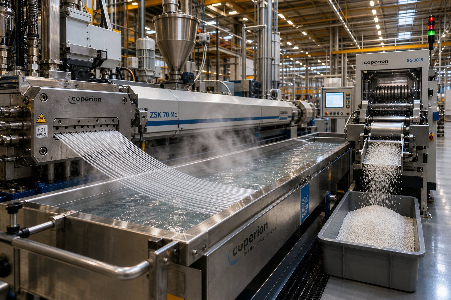
Finally, the fully compounded and degassed melt reaches the die — a shaped orifice that forms the material into strands, sheets, or profiles. From the die, downstream equipment takes over: a water bath or air-cooling system solidifies the extrudate, and a pelletizer or haul-off unit cuts or draws it into its finished form.
Each of these zones relies on specific screw elements arranged in a deliberate sequence along the barrel. The choice, order, and geometry of those elements determine whether the process succeeds or struggles — which raises a practical question: how exactly are those modular screw elements designed, and how do engineers decide which combination to use?
Modular Screw Element Design and Configuration
Picture a set of building blocks, each with a unique shape and purpose, that you can snap together in any order on a central rod. That is essentially how a twin screw extruder's screw profile works. Individual screw elements — conveying segments, kneading blocks, mixing elements, and reverse-flighted sections — slide onto a splined shaft and lock into position. Rearrange them, and you fundamentally change what the machine does to the material passing through it.
This modular approach is the single biggest advantage separating twin screw systems from single screw designs, where the screw is typically machined as one continuous piece with a fixed geometry. A twin screw and barrel system built around interchangeable elements lets engineers reconfigure the same extruder for dozens of different formulations without purchasing new hardware. The screw profile, as NC State Extension research describes, is "a blend of art and science" — every material responds differently to heat and shear, so no single arrangement works universally.
Types of Screw Elements and Their Functions
Each element category performs a specific job within the barrel extruder. Understanding what each one does — and where it belongs in the screw profile — is the foundation for building effective processing zones.
| Element Type | Primary Function | Shear Level | Typical Barrel Zone Placement |
|---|---|---|---|
| Conveying (Transport) Elements | Forward material transport and pressure generation | Low | Feed zone, transitions between processing zones, and metering zone near the die |
| Kneading Blocks (30° stagger) | Moderate melting and mixing with forward conveying action | Medium | Early melting zone or gentle mixing sections |
| Kneading Blocks (60°–90° stagger) | Intensive dispersive mixing — breaks agglomerates, melts solids rapidly | High to Extreme | Primary melting zone and high-shear mixing zone |
| Toothed Mixing Elements (TME/ZME) | Distributive mixing — splits and recombines melt flow for spatial uniformity without excessive shear | Low to Moderate | Downstream mixing zones, color or additive blending sections |
| Reverse (Left-Handed) Elements | Pressure buildup, back-mixing, melt seal creation | High (localized) | Immediately upstream of vent ports or reaction zones |
A few details in this table deserve closer attention. Kneading blocks are the heart of the twin screw barrel's mixing capability. Their stagger angle — the angular offset between each disc in the block — dramatically changes behavior. At 30°, the discs still push material forward while applying moderate shear. Increase that angle to 60° or 90°, and the element stops conveying almost entirely, forcing material to dwell longer under intense shear. As industry engineering guides note, a 90° stagger angle produces maximum residence time and extreme shear, making it powerful for dispersive mixing but risky for heat-sensitive polymers.
Toothed mixing elements work on a completely different principle. Instead of shearing material between disc surfaces, they use gear-like teeth to repeatedly split and recombine the melt stream. Imagine shuffling a deck of cards over and over — you achieve thorough spatial distribution without crushing the cards. This makes TME and ZME elements ideal for blending color concentrates, distributing liquid additives, or mixing polymer blends where particle breakdown is not needed.
Reverse elements deserve special attention because they seem counterintuitive — why would you push material backward in a machine designed to move it forward? The answer is controlled restriction. By creating localized back-pressure, reverse elements force the upstream zone to fill completely, which builds a melt seal. That seal is essential before vent ports, because it prevents vacuum from pulling air backward through the barrel instead of drawing volatiles out of the melt.
Designing a Screw Configuration for Specific Goals
Knowing what each element does is only half the puzzle. The real engineering challenge lies in sequencing them along the extruder screw and barrel to create distinct, coordinated processing zones. Here is how experienced engineers approach common scenarios:
- High-filler compounding (calcium carbonate, talc, glass fiber): Use aggressive kneading blocks with 60° stagger angles in the primary mixing zone to break filler agglomerates and achieve thorough wet-out. However, if you are incorporating glass fibers, position a downstream side-feed port followed by gentle conveying elements — excessive kneading after fiber addition causes severe fiber length degradation, destroying the compound's mechanical properties.
- Shear-sensitive materials (PVC, certain biodegradable polymers): Replace aggressive kneading blocks with toothed mixing elements and lower-angle kneading discs. The goal is adequate blending without generating the high melt temperatures that trigger degradation. Shorter kneading sections and longer conveying zones help keep energy input under control.
- Devolatilization-intensive processes (recycling contaminated feedstock, removing solvents): Place reverse elements immediately upstream of each vent port to create a reliable melt seal. Follow the vent section with deep-flighted conveying elements that expose maximum melt surface area, allowing trapped moisture and volatiles to escape efficiently under vacuum.
- Reactive extrusion (grafting, polymerization, crosslinking): Extend the mixing and residence time zones by combining neutral 90° kneading blocks with reverse elements. This ensures reactants have enough contact time to complete the desired chemical reaction before the melt exits the barrel.
An important point that often gets overlooked: barrel segment modularity mirrors screw modularity. Just as individual screw elements slide on and off the shaft, the barrel itself is built from segmented sections that can be open (for side feeding), closed (for standard processing), or vented (with ports for atmospheric or vacuum degassing). This means the entire barrel extruder system — not just the screws — can be reconfigured to match new process requirements. Need to add a second vent port for a moisture-heavy recycled feedstock? Swap in a vented barrel segment and place matching reverse and conveying elements on the screws. The flexibility runs through every layer of the machine.
Designing a screw profile is ultimately about managing trade-offs. More aggressive mixing improves dispersion but raises melt temperature. Longer residence time aids reactions but risks thermal degradation. Higher fill levels boost throughput but can overload torque. Every element you add, remove, or reposition shifts these balances — which is why the same extruder can produce vastly different results with two different screw configurations, even when processing the same material at the same feed rate.
This flexibility naturally raises a related question: if screw element design governs how a twin screw extruder processes material, does the direction those screws rotate matter just as much? The answer shapes which configuration — co-rotating or counter-rotating — suits a given application.
Co-Rotating vs Counter-Rotating Twin Screw Extruders
Rotation direction might sound like a minor mechanical detail, but it fundamentally changes how material behaves inside the barrel. Two screws turning the same way produce a completely different flow field, shear profile, and mixing character than two screws turning in opposite directions. Choosing between a co-rotating twin screw extruder and a counter-rotating twin screw extruder is not a matter of preference — it is a decision driven by the material you are processing and the outcome you need.
Co-Rotating Intermeshing Twin Screw Extruders
In a co-rotating configuration, both screws turn in the same direction — typically at high speed. Material entering the intermeshing zone is forcibly handed off from one screw flight to the next, tracing that distinctive figure-eight flow path discussed earlier. This geometry creates intense shear fields in two critical locations: between the screw flights themselves and between each screw tip and the barrel wall.
What does this mean in practice? You get aggressive, thorough mixing combined with a strong self-wiping action. Because the screws constantly scrape material off each other's surfaces, dead zones virtually disappear. The residence time distribution stays tight, which matters enormously when processing thermally sensitive formulations or running reactive extrusion where even a few seconds of extra heat exposure can trigger degradation or unwanted side reactions.
The co rotating twin screw extruder also benefits from its modular screw design to the fullest extent. Engineers can freely combine conveying elements, kneading blocks, and mixing elements to build precisely tailored processing zones — high-shear sections for filler dispersion, gentle distributive zones for color blending, and melt seal regions for devolatilization. This flexibility, paired with the machine's naturally high mixing intensity, explains why co-rotating designs dominate applications like:
- Polymer compounding with mineral fillers, glass fibers, or nanoparticles
- Masterbatch and color concentrate production
- Reactive extrusion — grafting, compatibilization, and in-line polymerization
- Devolatilization of moisture-laden or solvent-rich melts
- Polymer blending and alloy development
Parallel twin screw extruder configurations are standard for co-rotating machines, meaning both screws maintain a constant diameter from feed end to discharge. This allows for the longest possible processing length and the most flexible barrel zone arrangement — a key reason high-L/D co-rotating parallel machines have become the workhorses of modern compounding lines.
Counter-Rotating Intermeshing Twin Screw Extruders
Flip one screw's rotation direction, and the physics inside the barrel shift dramatically. In a counter-rotating design, the screws turn in opposite directions. At the intermeshing zone, material is drawn inward between the two screws rather than swept sideways, creating what engineers describe as a calendering effect — think of two rollers squeezing dough between them. The material undergoes compressive and elongational deformation rather than the intense rotational shear characteristic of co-rotating systems.
The practical result is lower shear stress and reduced shear-induced heat generation. Material transport also relies more directly on screw rotation itself, producing a highly positive pumping action even at low speeds. Counter-rotating machines typically operate at high fill levels, which contributes to their stable, pressure-driven conveying.
Why does this matter? Consider rigid PVC — a material with a low thermal decomposition temperature and poor melt flow. Expose it to the aggressive shear of a co-rotating machine, and you risk thermal degradation before the material even reaches the die. A counter-rotating twin screw extruder, by contrast, allows processing at lower temperatures and gentler conditions, preserving material integrity throughout the barrel.
Counter-rotating configurations come in two geometric variants:
- Parallel counter-rotating — Both screws maintain a uniform diameter, similar in layout to their co-rotating counterparts but with fundamentally different flow behavior. Used for applications requiring moderate mixing with strong pressure buildup.
- Conical counter-rotating — The screws taper from a large diameter at the feed end to a smaller diameter at the discharge end. This conical twin screw extruder design creates a natural compression zone as material moves downstream. The larger feed zone accepts bulky, low-density powder efficiently, while the narrowing metering zone builds pressure for stable die extrusion.
Conical designs are the standard choice for PVC pipe and profile extrusion lines worldwide. Their tapered geometry also permits larger bearings at the feed end, enabling higher torque transmission in a compact footprint — a practical engineering advantage when floor space and machine cost are considerations.
Choosing the Right Rotation Configuration
Selecting between co-rotating and counter-rotating is not about which machine is "better" — it is about matching the equipment to the job. A structured approach helps cut through the complexity. Start with your material, define your processing goal, consider your production volume, and let those factors guide you toward the right configuration.
Here is a practical decision path:
- Material type: Is it thermally stable and able to tolerate high shear (polyolefins, engineering plastics)? Co-rotating is your default. Is it heat-sensitive or shear-sensitive (rigid PVC, certain bioplastics)? Counter-rotating deserves serious consideration.
- Processing goal: Do you need intensive dispersive mixing, reactive extrusion, or multi-stage devolatilization? Co-rotating parallel machines excel here. Is the goal gentle melting and direct extrusion into a finished profile or pipe? Counter-rotating — especially conical — is purpose-built for this.
- Production volume and flexibility: High-volume compounding with frequent recipe changes favors co-rotating designs because of their modular screw versatility. Dedicated PVC extrusion lines running a consistent product typically favor counter-rotating conical extruders optimized for that single task.
The table below puts the key differences side by side for a quick comparison between co-rotating and counter-rotating twin screw extruder configurations:
| Dimension | Co-Rotating Intermeshing | Counter-Rotating Intermeshing |
|---|---|---|
| Shear Level | High — strong rotational shear at intermeshing zone | Low to moderate — compressive and elongational deformation |
| Mixing Intensity | Excellent dispersive and distributive mixing | Moderate — effective for gentle blending and calendering-style dispersion |
| Pressure Generation | Moderate — relies on die restriction and downstream elements | High — positive displacement pumping, especially in conical designs |
| Self-Wiping Capability | Strong — continuous scraping eliminates dead zones | Limited — geometry does not produce the same wiping action |
| Geometric Variants | Parallel | Parallel and conical |
| Typical Materials | Polyolefins, engineering plastics, filled compounds, polymer blends, reactive systems | Rigid PVC, heat-sensitive polymers, high-fill-level formulations |
| Primary Applications | Compounding, masterbatch, reactive extrusion, devolatilization, recycling | PVC pipe, PVC profile, sheet extrusion, low-shear direct forming |
Notice a pattern in this comparison? The co-rotating machine is the generalist — flexible, modular, and built for complexity. The counter-rotating machine is the specialist — optimized for specific materials and forming tasks where gentle handling and strong pumping action outweigh the need for mixing versatility. Neither replaces the other; they serve different corners of the extrusion landscape.
Of course, rotation direction and screw configuration only tell part of the story. Both types of twin screw extruders still compete with their simpler cousin — the single screw extruder — and understanding where each machine truly outperforms the other requires a direct, specification-by-specification comparison.
Twin Screw vs Single Screw Extruder Comparison
Picking between a double screw extruder and a single screw machine is one of the most consequential equipment decisions an engineer or plant manager will make. Get it right, and your line runs efficiently for years. Get it wrong, and you are stuck with capability gaps that no process tweak can overcome. The challenge? Most comparisons available online list a few bullet points without connecting those differences to real production outcomes. The table below changes that by putting every major performance dimension side by side in one place.
Key Performance Differences at a Glance
Rather than generalizing, consider each dimension in terms of how it affects your daily operations — from mixing quality and throughput stability to maintenance budgets and capital planning.
| Performance Dimension | Twin Screw Extruders | Single Screw Extruder |
|---|---|---|
| Mixing Capability | Excellent — delivers both distributive and dispersive mixing through modular kneading and mixing elements | Limited — relies primarily on drag flow and barrel-wall shear, producing adequate but basic mixing |
| Process Flexibility | High — modular screw and barrel segments can be rearranged for different formulations on the same machine | Low — screw geometry is typically fixed, requiring a new screw for significantly different processes |
| Throughput Consistency | Stable — starve feeding with gravimetric control decouples feed rate from screw speed, ensuring precise output | Variable — throughput depends on drag flow, making it sensitive to material viscosity changes and feed behavior |
| Material Versatility | Handles high-filler loads, reactive systems, multi-component blends, and recycled feedstock with ease | Best suited for single-polymer processing of pre-compounded or uniform feedstock |
| Residence Time Distribution | Narrow and uniform — self-wiping action prevents stagnation, ensuring consistent thermal history | Broad — material can linger in low-flow zones, leading to uneven heat exposure |
| Devolatilization | Highly effective — multiple vent ports with melt seals allow staged vacuum degassing | Limited — typically one vent port with less efficient melt surface renewal |
| Capital Cost | Higher — complex gearbox, tight screw tolerances, and modular components increase initial investment | Lower — simpler design translates to a more affordable purchase price |
| Maintenance Complexity | Higher — tight intermeshing clearances require precision wear monitoring and periodic element replacement | Simpler — fewer wearing components and wider tolerances make routine upkeep more straightforward |
| Ideal Use Cases | Compounding, reactive extrusion, masterbatch production, devolatilization, plastics recycling, pharmaceutical hot melt extrusion | Single-polymer extrusion of pipe, film, sheet, and profile using pre-compounded material |
You will notice that twin screw extruders dominate wherever the process demands intensive mixing, multiple feeding stages, or tight quality control. The self-wiping screw geometry, modular element design, and independent feed-rate control discussed in earlier sections translate directly into the performance advantages shown above. A screw extruder with a single flight simply cannot replicate that level of process control — not because of poor engineering, but because the underlying conveying mechanism is fundamentally different.
When a Single Screw Extruder Is the Better Choice
It would be misleading to suggest that twin screw machines are always the right answer. For many production lines, a single screw extruder is not just adequate — it is genuinely superior.
Consider film blowing. The process requires steady, pulsation-free melt delivery at high throughput, and the material is typically a single pre-compounded polymer. A single screw machine delivers exactly this, at a fraction of the capital and maintenance cost. The same logic applies to pipe extrusion of pre-compounded PVC or polyethylene, profile extrusion with stable formulations, and sheet lines running single-resin feedstock. In each of these cases, the material arrives already compounded and homogeneous — there is nothing left for intensive mixing to accomplish.
Simplicity carries real operational value, too. Single screw extruders have fewer precision-wear components, wider mechanical tolerances, and lower spare-parts inventory requirements. For plants running around the clock on a single product, the lower downtime risk and reduced maintenance overhead can outweigh any mixing advantage a twin screw system would offer.
The decision ultimately comes down to a straightforward question: does your process need to transform the material, or simply melt and pump it? If you are blending, filling, reacting, or removing volatiles, twin screw extruders earn their higher price tag every production hour. If you are melting a clean, uniform resin and shaping it into a finished product, a single screw extruder does the job more efficiently and economically.
Equipment selection, however, extends well beyond screw count and rotation direction. The machine's physical dimensions — particularly its length-to-diameter ratio — and the interplay of operating parameters like screw speed, temperature, and torque ultimately determine whether your chosen extruder delivers its full potential.
Key Specifications and Operating Parameters
You have selected your rotation direction, decided between co-rotating and counter-rotating, and even mapped out a preliminary screw element configuration. But none of those choices deliver results in isolation. The physical dimensions of the twin screw extruder machine — and the operating parameters you dial into the control panel — determine whether your carefully designed screw profile actually produces the quality and throughput you need.
Understanding L/D Ratio and Its Impact
If screw diameter defines how much material the machine can handle per revolution, then L/D ratio defines how much work the machine can do to that material before it exits the die. L/D — length-to-diameter ratio — is simply the total processing length of the screw divided by its outer diameter. A 50 mm twin-screw extruder machine with a 2,400 mm process section, for example, has an L/D of 48:1.
Why does this number matter so much? Every unit operation you need — feeding, melting, mixing, side feeding, devolatilization, pressure buildup — occupies barrel zones along the screw length. A higher L/D gives you more zones to work with, meaning more room for additional process steps without sacrificing performance in existing ones.
Industry L/D ratios typically fall into three practical ranges, each suited to different levels of processing complexity:
| L/D Range | Processing Complexity | Typical Applications |
|---|---|---|
| 20:1 – 28:1 | Simple — short residence time, limited unit operations | Color masterbatch, thermally sensitive compounding, simple blending |
| 28:1 – 36:1 | Moderate — balanced mixing and residence time | Engineering plastics compounding, fiber reinforcement, medium-filler compounds |
| 36:1 – 48:1+ | Complex — multiple feeding points, venting stages, and extended mixing zones | High-filler compounding, reactive extrusion, devolatilization, recycled-feedstock processing |
A practical guide from Wanplas notes that shorter ratios in the 20:1 to 28:1 range work well for materials sensitive to thermal degradation because they limit heat exposure, while longer ratios of 36:1 and above provide the extended residence time needed for thorough degassing and reactive chemistry. The most commonly used L/D range — 32:1 to 48:1 — reflects the reality that modern compounding operations typically require at least one downstream side-feed port and one or two vacuum vents, each consuming several diameters of barrel length.
Keep in mind that a longer L/D is not automatically better. Every additional barrel section adds cost, increases mechanical deflection risk on the screw shafts, and extends the thermal history of the melt. The goal is to use enough length for the process — and no more.
Critical Operating Parameters
With the machine's geometry fixed, five key operating parameters govern day-to-day performance of the extruder system. Adjust any one, and the others respond — making process control a balancing act rather than a set-and-forget exercise.
- Screw speed (RPM) — Controls shear rate and mixing intensity. Higher RPM increases shear input, which improves dispersion but also raises melt temperature through viscous dissipation. As industry experts at Plastics Technology note, co-rotating machines can reach 1,200 RPM or more, giving operators a wide shear range to optimize compounding efficiency.
- Barrel temperature profile — A series of independently controlled heating and cooling zones along the barrel length. Temperatures typically ramp up from the feed section to the melting zone, then stabilize or decrease slightly through mixing and venting zones. The profile shapes both melt viscosity and reaction kinetics, making it a primary quality lever.
- Feed rate and its interaction with screw speed — In starve-fed operation, the feed-rate-to-screw-speed ratio directly governs fill level inside the barrel. A low ratio means the screws run mostly empty, increasing shear exposure per unit of material and extending residence time. A high ratio fills the channel more completely, boosting throughput but reducing mixing intensity. This decoupled relationship is the defining operational advantage of a starve-fed twin screw extruder machine — you can tune residence time and shear independently of output rate.
- Torque — The rotational force the gearbox transmits to the screw shafts. Torque is often the first parameter to hit a ceiling during process optimization. When the motor reaches its maximum torque rating, you cannot increase feed rate or screw speed further without risking shaft damage or gearbox failure. Monitoring torque as a percentage of maximum capacity — a metric sometimes called specific energy when normalized per kilogram of throughput — is essential for troubleshooting and scale-up.
- Die pressure — The back-pressure generated at the extruder exit by the die geometry and any downstream filtration. Higher die pressure forces material backward into the metering zone, increasing fill level and melt temperature in the final barrel sections. Excessive pressure raises energy consumption and can degrade temperature-sensitive products — a practical reason to keep die and screen pack designs as open as the product allows.
Here is where these parameters connect into a single, intuitive picture. Imagine you are running a mineral-filled polypropylene compound. You increase the filler loading from 30% to 50%, which raises melt viscosity. The motor immediately draws more torque. If torque hits its limit, you have two options: reduce screw speed (lowering shear and throughput) or reduce feed rate (lowering fill level and throughput). Either way, capacity drops unless the machine was originally specified with enough torque headroom for that higher filler load.
This interdependence is why experienced operators treat specific energy — kilowatts applied per kilogram of throughput — as their most reliable process fingerprint. A consistent specific energy reading across batches signals stable processing conditions. A sudden shift, even at unchanged setpoints, flags a change in feedstock properties or machine wear that demands attention before product quality suffers.
Specifications and parameters define what a machine can do. Yet the real question for most teams is what a twin screw extruder should do — which industries and applications genuinely benefit from its capabilities, and where does it deliver advantages that no other equipment can match?
Industry Applications and Why Twin Screws Excel
A compounding extruder processing glass-fiber-reinforced nylon operates under entirely different demands than a pharmaceutical system producing amorphous solid dispersions — yet both rely on the same core machine. That versatility is not accidental. The modular screw design, precise residence time control, and independent feed-rate management discussed in earlier sections translate into tangible advantages across a surprisingly broad range of industries. The key is understanding why each sector reaches for twin screw technology instead of simpler alternatives.
Plastics Compounding, Recycling, and Pelletizing
Plastics compounding remains the largest single application for twin screw extruders, and it is easy to see why. Every formulation challenge that makes compounding difficult — high filler loadings, multi-component blends, reactive additives, moisture-laden recycled feedstock — plays directly to the machine's strengths.
- Masterbatch and color concentrate production — Dispersing pigments uniformly into a carrier resin demands both dispersive mixing (to break agglomerates down to primary particle size) and distributive mixing (to spread those particles evenly throughout the melt). A twin screw compounding extruder achieves both in a single pass by combining kneading blocks with toothed mixing elements, eliminating the need for pre-mixing steps or multiple extrusion passes.
- Filled and reinforced compound preparation — Mineral fillers like calcium carbonate and talc, along with reinforcing fibers such as glass and carbon fiber, require careful incorporation. Side feeders introduce these materials downstream of the melting zone, and the modular screw profile lets engineers place gentle conveying elements after the feed point to preserve fiber length while still achieving thorough wet-out. This level of zone-by-zone control simply is not possible on a fixed-geometry single screw machine.
- Polymer blending and alloy development — Blending immiscible polymers — think nylon with polypropylene, or ABS with polycarbonate — requires compatibilizers and intense mixing to create stable morphologies. The narrow residence time distribution of an extruder for polymer blending ensures every particle of the blend receives the same thermal and mechanical history, which is critical for consistent impact strength, surface finish, and dimensional stability in the final product.
- Plastics recycling — Post-consumer and post-industrial waste streams arrive contaminated, mixed, and moisture-laden. Twin screw extruders handle these challenges through multi-stage devolatilization (stripping water and volatile contaminants via vacuum vents), intensive mixing (homogenizing mixed polymer streams), and filtration compatibility (maintaining stable die pressure even with screen changers in-line). A screw extruder granulator system at the discharge converts the cleaned, compounded melt into uniform pellets ready for reprocessing — closing the loop on material that would otherwise go to landfill.
In each of these plastics applications, the common thread is transformation. Raw ingredients enter the machine as separate, incompatible components and exit as a finished compound with properties none of those ingredients possessed alone.
Pharmaceutical, Food, and Emerging Applications
The same processing principles that make twin screw extruders dominant in plastics have opened doors into sectors where precision, cleanability, and regulatory compliance matter just as much as throughput.
- Pharmaceutical hot melt extrusion (HME) — Imagine a poorly soluble drug molecule that the body cannot absorb efficiently in crystalline form. By dispersing it into a polymeric carrier at the molecular level — creating what pharmacists call an amorphous solid dispersion — bioavailability improves dramatically. Twin screw extruders are the preferred platform for this process because they deliver consistent mixing, precise residence time control, and continuous manufacturing capability aligned with FDA quality-by-design frameworks. The solvent-free nature of HME eliminates drying steps, reducing production complexity and environmental impact. Beyond solid dispersions, twin screw systems also support pharmaceutical granulation, where controlled barrel fill levels and screw speed enable fine-tuning of granule size and tablet tensile strength. The technology even integrates with fused deposition modeling (FDM) 3D printing, where HME-produced filaments enable personalized dosage forms with tailored drug release profiles.
- Food-grade extrusion — Breakfast cereals, snack puffs, textured vegetable protein, and pet food all share a common manufacturing thread: cooking extrusion on twin screw machines. The ability to precisely control temperature, moisture, shear, and residence time allows food engineers to manipulate starch gelatinization, protein texturization, and expansion ratios with a level of consistency that batch cooking processes cannot match. High-moisture extrusion for plant-based meat alternatives has become one of the fastest-growing segments, relying on long-barrel twin screw systems to create the fibrous, muscle-like textures consumers expect.
- 3D printing filament production — Consistent filament diameter and homogeneous material properties are non-negotiable for reliable 3D printing. Twin screw extruders produce filament from custom polymer blends — including color-matched, filled, or composite formulations — with the tight dimensional tolerances and uniform melt quality that single screw systems struggle to achieve at small diameters.
- Battery electrode manufacturing — As the energy storage industry expands, twin screw extruders have taken on a critical role in producing electrode materials for lithium-ion batteries. Mixing active materials, binders, and conductive additives into a homogeneous slurry — or performing dry electrode processing — demands the precise, repeatable blending that twin screw systems provide. Uniformity in electrode composition directly affects battery capacity, cycle life, and safety, making mixing quality a performance-critical specification rather than a manufacturing convenience.
- Biodegradable bioplastic compounding — Materials like PLA, PHA, and starch-based blends are notoriously shear-sensitive and moisture-sensitive. A compounding twin screw extruder configured with gentle mixing elements and effective vacuum devolatilization can process these materials without triggering the hydrolytic degradation that destroys molecular weight and mechanical properties. As sustainability regulations drive adoption of biodegradable packaging and single-use alternatives, this application segment continues to grow rapidly.
What connects these diverse applications — from recycled polyethylene pellets to pharmaceutical tablets to battery electrodes — is a shared need for controlled, reproducible material transformation. The twin screw extruder's modular design, self-wiping geometry, and decoupled process parameters make it uniquely suited to meet that need across scales ranging from a few grams per minute in a research lab to several tons per hour on a production floor.
That range of scales, however, introduces its own challenge. A formulation perfected on a small machine does not automatically perform the same way on a larger one. Bridging the gap between laboratory development and full-scale production requires a deliberate, physics-driven scale-up strategy — one that accounts for the geometric and thermodynamic differences between machine sizes.
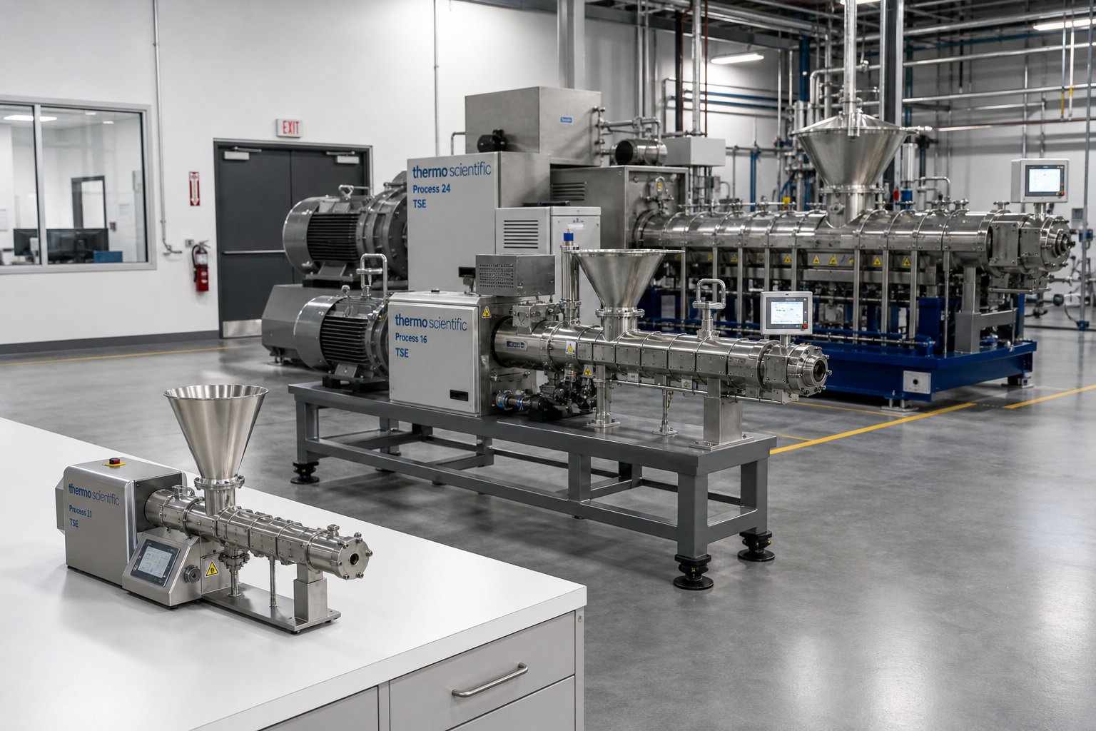
Scaling Up from Laboratory to Production Extruders
A formulation that runs beautifully on a 26 mm laboratory twin screw extruder does not automatically behave the same way on a 92 mm production machine. Scaling up twin screw extrusion is one of the most misunderstood steps in the commercialization process — nearly every equipment brochure mentions "scalability" as a benefit, but few explain the physics behind it or the pitfalls that derail real-world transitions. The reality? Scale-up is governed by a handful of core principles, and ignoring any one of them can turn a proven laboratory recipe into an unstable, off-spec production nightmare.
From Benchtop to Laboratory to Production Scale
The journey from concept to commercial product typically follows a staged progression, with each step serving a distinct purpose in de-risking the final production process.
A benchtop twin screw extruder — with screw diameters in the 10-20 mm range — is the starting point for formulation screening. These compact machines require as little as 5-20 grams of material per run, making them invaluable when working with expensive APIs or novel polymers where raw material availability is limited. Their role is straightforward: answer the question "can this formulation be extruded at all?" and identify promising candidates before committing larger quantities of material.
A laboratory twin screw extruder, typically in the 20-35 mm diameter range with throughputs from roughly 3 to 50 kg/h, is where real process development happens. At this scale, the machine's design attributes — its screw element geometry, OD/ID ratio, L/D ratio, and barrel configuration — closely mirror those of full-production equipment. This geometric similarity is not a minor detail. It is the foundation that makes everything learned at laboratory scale transferable to larger machines. Engineers use the lab scale extruder to optimize screw configuration, temperature profiles, screw speed, and feed rate, generating the baseline process data that will guide every subsequent scale-up decision.
Beyond the laboratory, pilot-scale machines (approximately 35-50 mm diameter) validate that laboratory-optimized conditions translate reliably to a larger barrel volume. Finally, production-scale extruders (60 mm and above) deliver the commercial throughput needed for economically viable manufacturing. The table below summarizes these typical scale categories:
| Scale Category | Screw Diameter Range | Typical Throughput | Primary Purpose |
|---|---|---|---|
| Benchtop | 10 – 20 mm | 0.1 – 5 kg/h | Formulation screening and feasibility studies with minimal material |
| Laboratory | 20 – 35 mm | 3 – 50 kg/h | Process development, screw design optimization, and small-batch production |
| Pilot | 35 – 50 mm | 20 – 200 kg/h | Process validation, customer samples, and intermediate-scale confirmation |
| Production | 60 mm and above | 200 – 4,000+ kg/h | Full commercial manufacturing at economically viable rates |
Three core principles govern how process conditions translate from one scale to the next:
- Geometric similarity — The screw diameter ratio (OD/ID), L/D ratio, and screw element designs must remain consistent across scales. A case study published by Plastics Technology used 26 mm, 40 mm, and 92 mm extruders that all shared an OD/ID ratio of 1.55 and an L/D of 44:1 — this consistency enabled direct comparison of processing conditions at every stage.
- Volumetric scale-up rules — When the process is limited by power and volume (rather than heat transfer), the maximum scaled-up throughput is estimated by the cube of the screw diameter ratio. In other words, doubling the screw diameter does not double throughput — it increases it roughly eightfold, because the free volume inside the barrel grows as the cube of the diameter.
- Specific mechanical energy (SME) consistency — SME, measured in kWh/kg, quantifies the mechanical energy transferred from the motor through the screws into the material. Matching this value across scales is often the single most reliable indicator of whether a larger machine will produce the same product quality as the smaller one.
Practical Scale-Up Considerations
Sounds straightforward enough — match the geometry, calculate the volumetric ratio, keep SME constant, and you are done. In practice, several physical realities complicate the transition.
Heat transfer efficiency decreases with scale. As screw diameter increases, the surface-area-to-volume ratio of the barrel drops dramatically. A small laboratory extruder has a high barrel surface area relative to its melt volume, so barrel heaters and cooling channels exert strong thermal control. Scale up to a 92 mm production machine, and that ratio shrinks. The barrel's ability to add or remove heat per kilogram of material weakens, meaning the melt temperature becomes increasingly driven by viscous shear heating rather than barrel setpoints. The same case study referenced above found that a low-viscosity raw material created a lubricating effect on the 92 mm machine that was never observed at the 26 mm scale — the larger extruder simply could not transfer enough shear energy into the compound, producing an SME of just 0.026 kWh/kg versus the laboratory's 0.083 kWh/kg. Unmelted pellets discharged through the die until engineers redesigned the screw profile and feeding configuration to compensate.
Residence time distribution shifts. Even with geometrically similar screws, the fill level and flow patterns inside a larger barrel are not perfect replicas of the smaller machine. Tip speed — the velocity at the outer edge of the screw flight — increases linearly with diameter at the same RPM. Higher tip speed raises peak shear, which can degrade temperature-sensitive materials or alter the morphology of polymer blends. To maintain similar shear conditions, engineers often reduce screw speed on the larger machine, which in turn changes the fill level and residence time distribution. As pharmaceutical scale-up research notes, these competing limits can result in lower throughput increases than theoretical calculations predict, requiring longer process sections, alternative screw designs, or adjusted operating speeds.
Screw configuration adjustments are almost always necessary. Simply replicating the laboratory screw profile at a larger scale is a starting point — not a solution. In the Plastics Technology case study, directly transferring the optimized 26 mm screw design to the 40 mm machine produced severe pressure fluctuations, phase separation, and unmixable material. Only after engineers increased melting and mixing intensity, lowered processing temperatures, and reduced screw speed did the process stabilize — achieving an SME of 0.079 kWh/kg, within 5% of the laboratory value. The same pattern repeated during the jump from 40 mm to 92 mm, requiring yet another round of screw redesign before the process matched its target SME of approximately 0.083 kWh/kg.
The good news? Modular screw and barrel design dramatically simplifies this iterative process. Because individual elements slide on and off splined shafts, engineers can replicate the laboratory's zone arrangement proportionally on the larger machine and then fine-tune individual sections — adding more kneading intensity here, extending a conveying zone there — without replacing the entire screw. The barrel's segmented construction offers the same flexibility: swapping a closed barrel section for a vented one, or adding a side-feed port at a new position, takes hours rather than weeks.
The most reliable scale-up strategy treats specific mechanical energy as the process fingerprint — if SME at production scale matches the value established on the laboratory extruder, product quality and process stability will follow.
A few additional practical guidelines help smooth the transition:
- Start with the power/volume scale-up equation when no heat-transfer limitations exist at the smaller scale. If the laboratory process runs without excessive barrel cooling demand, the cube of the diameter ratio is a reasonable first estimate of achievable throughput.
- Switch to the heat-transfer-limited equation (square of the diameter ratio) if the laboratory process already relies heavily on barrel cooling to manage melt temperature. This produces a more conservative — and often more realistic — throughput target.
- Run intermediate pilot-scale trials whenever the diameter jump exceeds roughly 2x. Skipping from a 26 mm lab scale extruder directly to a 92 mm production machine leaves too large a gap for comfortable prediction. A 40 mm pilot step surfaces problems — like the lubricating-effect issue described above — at a scale where they are cheaper and faster to solve.
- Monitor SME continuously, not just at steady state. Fluctuations in SME during a production run signal changes in feedstock properties, wear progression, or process drift that demand attention before off-spec product accumulates.
Scale-up is ultimately a risk-management exercise. Each intermediate step — from benchtop screening through laboratory optimization to pilot validation — narrows the uncertainty band before you commit to full production equipment. Skipping steps saves time in the short run but often costs far more when problems surface at a scale where every hour of downtime burns through raw material, labor, and delivery commitments.
With a proven formulation and a validated scale-up pathway in hand, the final decision becomes practical rather than theoretical: which specific twin screw extruder configuration, screw barrel combination, and equipment partner best fit your production requirements and long-term operational strategy?
Selecting the Right Twin Screw Extruder and Screw Barrel Partner
A validated formulation, a clear scale-up pathway, and a solid understanding of screw element design all point toward the same practical question: which specific machine configuration — and which equipment partner — will reliably deliver your target product quality, throughput, and return on investment? The answer lives at the intersection of material science, processing objectives, and production economics. Rather than guessing, work through the decision systematically.
Matching Configuration to Your Processing Requirements
Every selection decision flows through the same logical sequence. Start with what you are processing, define what you need to accomplish, set the scale, and let those inputs narrow the field. The checklist below distills the guidance from every preceding section into a single decision framework you can apply to any twin screw plastic extruder evaluation.
- Identify your material type — Is the base resin a thermoplastic polyolefin, an engineering polymer like nylon or polycarbonate, a thermoset, or a shear-sensitive material such as rigid PVC or PLA? Thermally robust materials tolerate the high-shear environment of co-rotating machines; heat-sensitive resins often require the gentler calendering action of counter-rotating designs.
- Define your processing objective — Compounding with high filler loadings, reactive extrusion, multi-stage devolatilization, and polymer blending all favor co-rotating parallel configurations with L/D ratios in the 36:1 to 48:1+ range and aggressive kneading block sequences. Direct extrusion of PVC pipe or profile, where gentle melting and strong pressure generation matter most, points toward counter-rotating conical extruders with shorter L/D ratios.
- Set the production scale — Laboratory development on a 20-35 mm machine, pilot validation at 35-50 mm, or full production at 60 mm and above? Match the screw diameter to your throughput target, keeping in mind that volumetric output scales roughly with the cube of the diameter ratio when power — not heat transfer — is the limiting factor.
- Select the screw element strategy — High-filler compounds demand aggressive dispersive mixing; shear-sensitive formulations need toothed distributive elements and low-angle kneading blocks. Devolatilization-heavy processes require reverse elements upstream of each vent port. Your screw profile should be designed before you finalize the machine purchase — not after.
- Evaluate torque and specific energy headroom — The gearbox must deliver enough torque to handle your most demanding formulation, not just your average one. A twin screw extruder price that looks attractive on paper means little if the drive system hits its torque ceiling at 70% of your target filler loading.
- Plan for future flexibility — Will you run multiple formulations on the same line? If so, modular barrel segments and a broad screw element library become essential. A plastic twin screw extruder that handles only today's recipe locks you into a narrow operational window as your product portfolio evolves.
Walking through these checkpoints before contacting twin screw extruder manufacturers saves time on both sides of the conversation. You arrive with clear specifications rather than vague requirements, and the supplier can recommend a configuration grounded in your actual process needs — not a generic catalog offering.
Finding Reliable Screw Barrel Support and Equipment Partners
Here is something easy to overlook during the excitement of specifying a new machine: the screw and barrel are the heart of any twin screw extruder, and their long-term performance depends entirely on metallurgy, manufacturing precision, and wear resistance. As ENTEK's metallurgy engineers have documented, the shift from nitrided tool steels to Hot Isostatic Pressed (HIP) alloys — now representing roughly 60% of screw and barrel production — reflects how demanding modern formulations have become. Abrasive glass-fiber compounds, corrosive fluoropolymer processes, and high-torque operating conditions all accelerate wear in ways that standard materials cannot withstand.
This means the relationship with your screw barrel supplier matters as much as the initial machine purchase. Screws and barrels are consumable components — they wear, they need refurbishment, and they occasionally need reconfiguration when you change formulations. A twin-screw extruder manufacturer may build an excellent machine, but if replacement wear parts arrive late, are machined to loose tolerances, or use the wrong alloy for your application, uptime and product quality suffer.
When evaluating partners, look for suppliers who understand the full range of extrusion applications rather than specialists limited to a single niche. Teams running pipe lines, profile extrusion, sheet production, pelletizing systems, and recycling operations all need screw barrel support — and sourcing those components from a single knowledgeable partner simplifies procurement, ensures metallurgical compatibility across your fleet, and reduces the risk of miscommunication when specifying replacement parts.
NANHAIYA is one such resource worth exploring. Their screw barrel support covers plastic extruder machines used across pipe, profile, sheet, pelletizing, recycling, and general processing lines — a breadth of application knowledge that benefits extrusion manufacturers and recycling plants managing diverse equipment inventories. For technical teams evaluating screw barrel solutions, their product page offers a practical starting point to assess whether their capabilities align with your specific processing requirements.
Ultimately, the best twin screw extruder for sale is not the one with the lowest sticker price or the longest feature list. It is the machine whose configuration, specifications, and support ecosystem match the realities of your material, your process, and your growth trajectory. Invest the time upfront to work through the decision framework above, secure a screw barrel partner who understands your applications at a metallurgical level, and the equipment will reward that diligence with years of consistent, high-quality production.
Frequently Asked Questions About Twin Screw Extruders
1. What is the difference between a twin screw extruder and a single screw extruder?
A twin screw extruder uses two intermeshing screws inside a figure-eight barrel, providing positive displacement conveying, self-wiping action, and modular screw elements that can be rearranged for different formulations. A single screw extruder relies on one screw and friction-based drag flow, offering simpler operation at lower cost but with limited mixing capability. Twin screw machines excel at compounding, reactive extrusion, and devolatilization, while single screw extruders are better suited for straightforward melting and pumping of pre-compounded polymers into finished forms like film, pipe, or sheet.
2. What is the purpose of a twin screw extruder?
A twin screw extruder transforms raw ingredients — polymer pellets, powders, fillers, fibers, and additives — into homogeneous compounds through controlled melting, mixing, devolatilization, and shaping. Its modular screw and barrel design allows engineers to configure distinct processing zones for dispersive mixing, distributive blending, volatile removal, and pressure buildup. This makes it the preferred machine for plastics compounding, masterbatch production, polymer recycling, pharmaceutical hot melt extrusion, food processing, and emerging applications like battery electrode manufacturing.
3. How do co-rotating and counter-rotating twin screw extruders differ?
Co-rotating twin screw extruders have both screws turning in the same direction, generating high shear, strong self-wiping action, and excellent dispersive and distributive mixing. They are ideal for compounding, reactive extrusion, and devolatilization. Counter-rotating extruders have screws turning in opposite directions, producing a gentler calendering effect with lower shear and stronger positive pumping action. Available in parallel and conical configurations, they are best suited for heat-sensitive materials like rigid PVC in pipe and profile extrusion. The choice depends on material sensitivity, mixing requirements, and the end product being manufactured.
4. What does L/D ratio mean on a twin screw extruder and why does it matter?
L/D ratio stands for length-to-diameter ratio — the total processing length of the screw divided by its outer diameter. It determines how many processing zones fit along the barrel. Ratios of 20:1 to 28:1 suit simple blending and thermally sensitive materials, while 36:1 to 48:1 or higher accommodate complex operations like multi-stage devolatilization, side feeding, and reactive extrusion. A higher L/D provides more room for unit operations but also increases capital cost, mechanical deflection risk, and thermal exposure. The goal is to match barrel length to process complexity without exceeding what the formulation requires.
5. How do you scale up a twin screw extrusion process from lab to production?
Successful scale-up relies on three principles: geometric similarity (maintaining consistent OD/ID ratio, L/D ratio, and screw element designs across machine sizes), volumetric scale-up rules (throughput scales roughly with the cube of the screw diameter ratio), and keeping specific mechanical energy (SME, measured in kWh/kg) consistent between scales. Challenges include reduced heat transfer efficiency on larger machines, shifted residence time distributions, and the need to adjust screw configurations. Running intermediate pilot-scale trials and monitoring SME continuously are critical practices. Sourcing screw barrel components from knowledgeable partners like NANHAIYA (nhyscrews.com) ensures metallurgical consistency across machine sizes.
Written by
Nanhaiya Technical Team
Zhoushan Nanhaiya Plastic Machinery Co., Ltd.
The Nanhaiya technical team supports screw and barrel manufacturing projects through application review, technical communication, custom manufacturing coordination, and production and quality control.
Discuss Your Application
Related Articles
More insights on screw barrel technology and plastics processing.

Extruder Machine Decoded: From Raw Pellet To Finished Product
Oct 6, 2026
Learn how an extruder machine works, compare single-screw vs. twin-screw types, and get expert guidance on specs, troubleshooting, and selection.
Read Article
PE Pipe Making Machine Decoded: From Raw Resin to Flawless Pipe
Oct 4, 2026
Learn how a PE pipe making machine works, from resin to finished pipe. Covers components, material grades, automation, troubleshooting, and buyer selection tips.
Read Article
PVC Profile Making Machine Decoded: From Raw Resin To Profit
Oct 3, 2026
Learn how a PVC profile making machine works — extrusion process steps, key technical parameters, die design, calibration methods, maintenance, and total cost of ownership.
Read ArticleLooking for something else?
Search by material, symptom or product and jump straight to the relevant page.
These are navigation suggestions based on keyword matching — not a quotation, not a delivery commitment, and not a substitute for engineering review. Final specification is confirmed by our engineers against your drawings and processed material.
Need help with screw barrel selection?
Share your machine model, processed material and application. Our team can help with pricing and technical support.