

What Is a Twin Screw Extruder
Imagine a machine that can take raw plastic pellets, mineral powders, pharmaceutical compounds, or even food ingredients and transform them into a perfectly blended, precisely shaped product in a single continuous process. That machine exists, and it sits at the heart of countless manufacturing lines worldwide. It is the twin screw extruder.
Twin Screw Extruder Definition
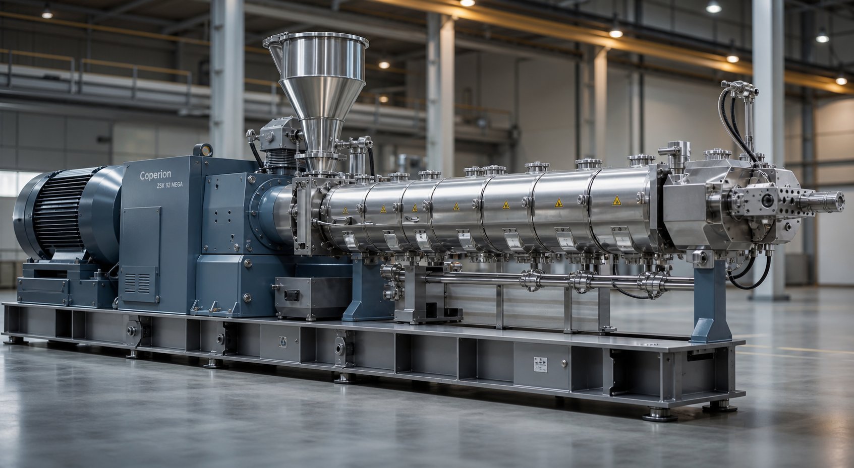
A twin screw extruder is a machine that uses two screws rotating side by side inside a heated barrel to convey, melt, mix, and shape materials. The screws can be intermeshing, where the flights of one screw engage the channels of the other, or non-intermeshing, where they operate independently within the same barrel. This dual-screw arrangement is what separates a twin-screw extruder from its simpler single-screw cousin and gives it far greater control over mixing intensity, residence time, and process flexibility.
A twin screw extruder is a continuous processing machine in which two co-rotating or counter-rotating screws operate inside a closely fitted, heated barrel to convey, melt, compound, and shape materials with superior mixing performance and precise process control.
Why does this twin screw design matter so much? Single-screw machines rely primarily on friction-driven drag flow to move material forward. They work well for straightforward melting and shaping tasks, but they struggle when a process demands intensive blending of multiple ingredients or tight control over temperature and shear. A twin screw extruder solves those problems through positive displacement conveying and self-wiping screw geometry, giving engineers the ability to independently tune throughput, mixing energy, and thermal exposure. The result is a level of versatility that a single screw simply cannot match.
Why Twin Screw Extrusion Matters in Modern Manufacturing
When you look across industries that rely on continuous processing, the twin screw extruder keeps showing up. In plastics compounding, it blends base polymers with fillers, stabilizers, and colorants to create engineered materials. In pharmaceuticals, hot-melt extrusion on twin screw platforms produces amorphous solid dispersions that improve drug bioavailability. Food manufacturers use these machines to cook, texturize, and shape cereals, snacks, and pet food. Recycling plants depend on them to reprocess contaminated post-consumer plastic waste that would overwhelm simpler equipment.
Understanding extruders meaning in each of these contexts reveals a common thread: the need for consistent, high-quality output from complex, multi-component feedstocks. Twin screw extrusion meets that need through modular hardware, where both barrel sections and screw elements can be rearranged to suit an entirely different process on the same machine frame.
This guide is built as a comprehensive, neutral educational resource. In the sections ahead, you will walk through every major component from motor to die, see exactly how material transforms zone by zone, compare co-rotating and counter-rotating configurations side by side, explore screw element design in detail, weigh twin screw performance against single screw alternatives, review real-world industry applications, and learn the key specifications and decision criteria for choosing the right machine. Each section builds on the last, so by the end you will have a clear, practical understanding of how twin screw extruders work and where they fit.
The best place to start is with the hardware itself, the physical components that make all of this possible.
Anatomy of a Twin Screw Extruder From Motor to Die
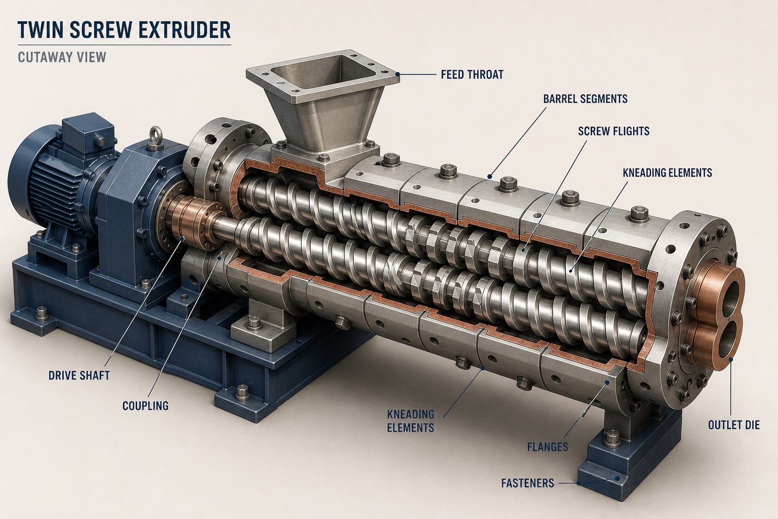
Every twin screw extruder, regardless of manufacturer or application, shares the same fundamental architecture. Think of it as a chain of specialized stations, each performing a distinct mechanical job. Understanding what each component does, and how they connect, is the foundation for making sense of everything else in this guide.
Core Mechanical Components
The journey begins at the drive motor. This is the prime mover of the entire extruder system, converting electrical energy into rotational force, or torque. Motor size directly determines how much energy can be transferred into the material during processing. A motor that is undersized for the application will stall under load; one that is oversized wastes capital and energy. You will often see AC motors paired with variable frequency drives so operators can adjust screw speed in real time.
Sitting between the motor and the screws is the gearbox, sometimes called the gear reducer. Its role is twofold: it reduces motor speed to the optimal RPM range for extrusion, and it splits the incoming torque evenly between two output shafts. Because both screws must rotate in precise synchronization, the gearbox is one of the most heavily engineered and expensive components in the machine. High torque density gearboxes allow processors to push more energy into difficult-to-mix formulations without mechanical failure.
The barrel assembly is where modular design truly shines. Rather than a single monolithic tube, a modern barrel extruder uses a series of individually bolted barrel segments. Each segment can serve a different purpose:
- Solid barrel sections for conveying and melting
- Vented barrel sections with openings for atmospheric or vacuum degassing
- Side-feed barrel sections with ports for introducing downstream fillers, fibers, or liquids
This modularity lets engineers reconfigure the same machine for completely different processes by rearranging, adding, or removing segments. The extruder feed barrel, typically the first segment in the series, features an open port on top where raw material enters. Volumetric feeders deliver material at a set volume per unit time, while gravimetric feeders use real-time weight measurement for tighter accuracy. Starve feeding, where the feeder controls throughput rather than the screw speed, is the standard approach for twin screw operations because it decouples feed rate from screw RPM.
Screw Shaft and Die Assembly
Here is a detail that surprises many newcomers: the extruder screw in a twin screw machine is not a single machined part. Each screw shaft is a splined steel rod onto which individual screw elements are stacked and locked. Conveying elements, kneading blocks, mixing elements, and reverse-flight elements can all be arranged in any sequence along the shaft. Swap the element order, and you fundamentally change how the machine processes material. This is the heart of what makes the twin screw and barrel platform so adaptable.
Because the screw elements and barrel liners endure extreme mechanical stress, abrasive fillers, and corrosive additives, sourcing precision-engineered components is essential for sustained performance. Providers like NANHAIYA offer screw barrel support tailored to pipe, profile, sheet, pelletizing, and recycling extrusion lines, connecting manufacturers and technical teams with components matched to their specific processing demands.
At the discharge end of the barrel sits the die head. This is where the molten, homogenized material is forced through a shaped opening to produce its final cross-section, whether that is a strand for pelletizing, a flat sheet, a blown film bubble, or a hollow pipe profile. Die geometry, combined with downstream cooling and haul-off equipment, determines the final product dimensions.
Temperature control runs the full length of the barrel. Electric heating bands wrapped around each segment bring the barrel to target temperatures during startup and processing, while internal cooling channels circulating water or oil remove excess heat generated by shear. Precise zone-by-zone temperature management prevents material degradation and ensures consistent melt quality.
Venting ports deserve special attention. Positioned at strategic locations along the barrel, these openings allow trapped moisture, air, residual monomers, and other volatiles to escape from the melt. Vacuum-assisted venting is common for demanding devolatilization tasks. Without effective venting, finished products can suffer from bubbles, surface defects, and compromised mechanical properties.
Here is the full component chain from input to output, laid out in sequence:
- Motor — delivers rotational energy
- Gearbox — reduces speed and splits torque to both shafts
- Feed Port — introduces raw material into the barrel
- Barrel Segments — modular heated sections forming the processing chamber
- Screw Elements — interchangeable conveying, kneading, and mixing components on splined shafts
- Vent Ports — release moisture and volatiles from the melt
- Die Head — shapes the melt into its final profile
Each of these components influences every other. A higher-torque gearbox enables more aggressive screw element configurations. A longer barrel with more segments provides space for additional mixing or venting zones. The interplay between these parts is what transforms a collection of hardware into a fully integrated extruder system capable of continuous, precision processing.
Of course, hardware alone does not tell the full story. The real magic happens when material enters that feed port and begins its transformation through a carefully orchestrated series of functional zones, each driven by specific screw element geometry.
How a Twin Screw Extruder Works Zone by Zone
Picture a handful of plastic pellets dropped into the feed port of a twin screw extruder. Within seconds, those solid granules begin a tightly controlled journey through heat, pressure, and shear, emerging at the other end as a perfectly homogenized melt ready to be shaped. What happens between those two points is not random. It is governed by a sequence of distinct functional zones, each engineered to perform a specific transformation. Understanding this twin screw extrusion process step by step is the key to understanding why these machines deliver results that simpler equipment cannot.
From Feed Throat to Die Head Step by Step
The process begins the moment raw material, whether pellets, powder, or a combination of both, drops through the feed throat into the first barrel segment. In most twin screw operations, material enters under gravity from a hopper mounted above the feed opening. Some processes use forced-feeding devices like crammer feeders when dealing with low-bulk-density materials that resist flowing freely. Either way, the goal is the same: get a consistent stream of solids into the screw channels.
Once inside, the deep-flighted screw elements in the feed zone catch the material and push it forward. These elements act like an Archimedes screw, using their helical flights to drag solids downstream. At this stage, the barrel temperature is kept relatively low. You do not want the material melting prematurely and sticking to surfaces before it has been properly conveyed.
As the material advances into the melting and plasticizing zone, things change quickly. Here, a combination of external barrel heating and internal frictional shear generated by kneading blocks begins softening the solid particles. Imagine squeezing cold butter between your palms. The pressure and friction warm it, and eventually it yields into a pliable mass. The same principle applies here, only the "palms" are precisely engineered kneading elements rotating at high speed. Progressively shallower screw channels compress the material, forcing more intimate contact between particles and heated barrel walls, accelerating the phase transition from solid to melt.
The now-molten material flows into the mixing and kneading zone, where the real blending work happens. If the formulation includes mineral fillers, color pigments, stabilizers, or a second polymer, this is where those components are dispersed and distributed throughout the melt. Intensive shear from narrow kneading discs breaks apart agglomerates, while distributive mixing elements split and recombine the melt stream repeatedly to ensure every region of the material reaches the same composition. This is the zone that defines the twin screw extrusion advantage: achieving true homogeneity at a molecular and micro-structural level.
Many processes include a devolatilization zone downstream of the mixing section. Here, the screw geometry opens up dramatically. Large-pitch conveying elements reduce the degree of fill inside the barrel, exposing a greater melt surface area to an open vent port. A vacuum pump connected to the port pulls trapped moisture, residual monomers, solvents, and dissolved gases out of the melt. Without this step, those volatiles would show up as bubbles, voids, or surface defects in the finished product. Upstream of each vent port, reverse-flight elements or reverse kneading blocks create a melt seal, a localized pressure barrier that prevents molten material from escaping backward through the vent opening.
Finally, the cleaned, homogenized melt reaches the metering and pumping zone. Shallow-channeled conveying elements compress the melt, building the stable, consistent pressure needed to push it through the die at the barrel's discharge end. Pressure fluctuations here translate directly into dimensional inconsistencies in the final product, so this zone's job is all about steadiness. The melt exits the die as a strand, sheet, film, or profile, depending on the downstream equipment waiting on the other side.
Functional Zones and the Screw Elements That Drive Them
Each of these zones does not exist in isolation. They are created entirely by the selection and sequencing of screw elements along the splined shaft, combined with the barrel temperature profile set by the operator. Swap a set of gentle conveying elements for aggressive kneading blocks, and you shift where melting begins. Add a reverse element, and you create a new melt seal for an additional vent port. This modularity is what makes screw extrusion on twin screw platforms endlessly configurable.
The table below maps each zone to its primary function, the screw elements that define it, and a general sense of where barrel temperatures typically fall relative to the material's processing window.
| Zone Name | Primary Function | Key Screw Elements | Typical Barrel Temperature Range |
|---|---|---|---|
| Feed Zone | Intake and initial forward conveyance of solid material | Deep-flighted, large-pitch forward conveying elements | Below or near the material's softening point |
| Melting / Plasticizing Zone | Transition from solid to molten state via shear and conducted heat | Progressively shallower conveying elements, kneading blocks | Approaching to slightly above the material's melt temperature |
| Mixing / Kneading Zone | Dispersive and distributive blending of all formulation components | Narrow kneading discs, gear-type or split-flight distributive mixing elements | At or slightly above the material's melt temperature |
| Devolatilization Zone | Removal of moisture, volatiles, and trapped gases under vacuum | Large-pitch conveying elements under vent port; reverse elements upstream for melt seal | At or slightly above the material's melt temperature |
| Metering / Pumping Zone | Pressure buildup for stable, consistent melt delivery to the die | Shallow-channel, standard or short-pitch forward conveying elements | Close to the target processing or die temperature |
Three engineering concepts tie all of these zones together and help process engineers fine-tune performance:
- Specific energy input — the total mechanical and thermal energy delivered per kilogram of material processed. Too little, and the melt is poorly mixed. Too much, and the polymer degrades.
- Fill fraction — the percentage of available screw channel volume actually occupied by material at any point along the barrel. Starve-fed twin screw extruders run partially filled in most zones, which gives engineers the freedom to control residence time independently of screw speed.
- Residence time distribution — a measure of how long individual material particles spend inside the extruder and how uniform that time is across the entire flow. A narrow residence time distribution means every particle receives nearly identical thermal and shear history, which is critical for heat-sensitive polymers and reactive extrusion processes.
These three parameters interact constantly. Increasing screw speed raises shear rate and reduces average residence time but also increases specific energy input. Adjusting feed rate changes fill fraction, which shifts both residence time and the intensity of mixing in partially filled zones. Mastering the twin screw extrusion process means learning to balance all three simultaneously.
Knowing what each zone does and which elements drive it naturally raises the next question: how do different machine configurations, co-rotating versus counter-rotating, parallel versus conical, change the way these zones behave and the results they produce?
Types of Twin Screw Extruders Compared
The zone-by-zone process described above does not play out identically on every twin screw machine. How those zones behave, how much shear the material experiences, how much pressure builds at the die, and which polymers the machine handles best, all depend heavily on two fundamental design choices: the direction the screws rotate and the geometric shape of those screws. Choosing the wrong configuration for your application is like putting a sprint engine in a tractor. The hardware matters.
Co-Rotating vs Counter-Rotating Configurations
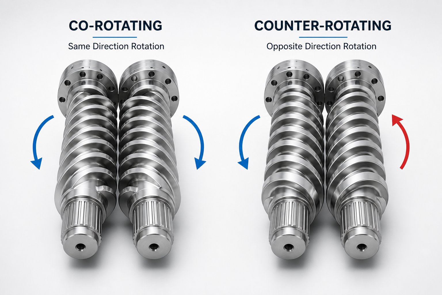
The most important classification in twin screw technology comes down to rotation direction. In a co rotating twin screw extruder, both screws turn the same way, typically at high speeds. In a counter-rotating design, the screws spin in opposite directions, creating an entirely different flow and pressure profile inside the barrel.
Why does rotation direction change everything? Consider the self-wiping mechanism. In an intermeshing co-rotating system, the flight of one screw continuously sweeps the channel of the other. Picture two gears rolling together: the leading edge of one cleans the trailing surface of its partner. This self-wiping action prevents material from stagnating in dead spots, which is critical when you are processing heat-sensitive polymers that degrade with extended residence time. The result is excellent distributive and dispersive mixing, tight residence time distribution, and high throughput flexibility. That combination makes the co rotating twin screw extruder the dominant platform for compounding, reactive extrusion, and masterbatch production.
Counter-rotating configurations tell a different story. Because the screws turn toward each other at the nip point, material gets trapped in roughly closed, C-shaped chambers between intermeshing flights and pushed forward almost like a positive displacement pump. This generates significantly higher pressure buildup with comparatively lower shear intensity. For applications like PVC pipe and profile extrusion, where excessive shear can degrade the polymer and where high die pressure is essential for forming thick-walled products, counter-rotating machines are the natural fit.
The table below lays out the key performance differences between co rotating and counter rotating twin screw extruder designs across the dimensions that matter most to process engineers:
| Dimension | Co-Rotating | Counter-Rotating |
|---|---|---|
| Shear Intensity | High — aggressive kneading and dispersive mixing | Moderate to low — gentler material handling |
| Mixing Capability | Superior distributive and dispersive mixing | Good distributive mixing; limited dispersive mixing |
| Self-Wiping | Excellent — flights continuously clean opposing channels | Limited — C-shaped chambers reduce but do not eliminate stagnation |
| Pressure Generation | Moderate — typically relies on downstream gear pumps for very high pressures | High — closed chamber design acts as a positive displacement pump |
| Throughput Range | Broad — starve-fed operation allows wide feed rate adjustment | Narrower — often flood-fed with throughput linked to screw speed |
| Typical Applications | Polymer compounding, masterbatch, reactive extrusion, pharmaceuticals, food | PVC pipe and profile extrusion, highly filled compounds, high-pressure forming |
One nuance worth noting: both co-rotating and counter-rotating designs can be either intermeshing or non-intermeshing. Intermeshing versions dominate commercial production because the screw engagement improves conveying efficiency and mixing quality. Non-intermeshing variants, where the screws rotate close to each other without engaging, are less common and tend to appear in specialized applications where gentler processing conditions are needed, such as handling shear-sensitive biomaterials.
Parallel vs Conical Screw Geometry
Rotation direction is only half the picture. The physical shape of the screws themselves introduces another layer of differentiation. A parallel twin screw extruder uses screws with a constant diameter from feed end to discharge end. This is the standard geometry for co-rotating compounders, and it offers a significant practical advantage: the L/D ratio can be adjusted by adding or removing modular barrel segments, giving engineers flexibility to lengthen the processing path for complex formulations without redesigning the screws.
A conical twin screw extruder, on the other hand, features screws that taper from a large diameter at the feed opening to a smaller diameter at the die end. Imagine two tapered cones meshing together inside a matching barrel. This geometry delivers two key benefits. First, the large feed-end diameter creates a generously sized intake area relative to the output diameter, which dramatically improves material intake for low-bulk-density powders like dry-blend PVC. Second, the natural taper provides a built-in compression ratio as material moves from the wide section to the narrow section, compacting and densifying the melt progressively without relying solely on screw element geometry.
Conical designs are almost exclusively paired with counter-rotating screw rotation and are the workhorse configuration for PVC window profiles, pipe, and siding. Their larger feed-end geometry also allows for bigger bearings and more robust gearbox internals, translating into higher torque capacity despite the compact output diameter. However, their fixed taper means limited flexibility in adjusting the L/D ratio, which is one reason they rarely appear in compounding applications where process versatility is paramount.
The choice between parallel and conical geometry ultimately maps back to the material and the process. If you need a versatile, reconfigurable platform that handles dozens of different formulations, a parallel twin screw extruder with modular barrels is the stronger choice. If you are running a dedicated PVC line where high compression, reliable powder intake, and robust torque delivery matter more than configurability, the conical twin screw extruder is purpose-built for that job.
Selecting the right configuration is a critical first step, but it is only the beginning. The real performance tuning happens at a more granular level, inside the screw elements themselves, where the sequence and style of individual conveying, kneading, and mixing components determine exactly what the machine does to the material passing through it.
Screw Element Design and Configuration Explained
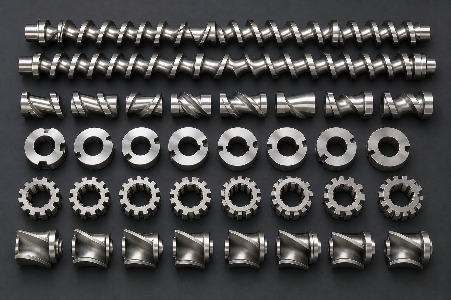
Every plastic extruder screw in a twin screw machine is assembled, not machined as a single piece. Individual elements slide onto a splined shaft and lock into position, each one designed to perform a very specific job on the material flowing through it. Change the order, swap one element for another, and you fundamentally alter how the machine processes your formulation. This is the feature that gives twin screws their legendary versatility, and it is also the aspect that demands the most engineering judgment.
Understanding Conveying, Kneading, and Mixing Elements
Four primary element types make up the toolkit that engineers draw from when building a screw profile. Each serves a distinct function, and understanding what they do individually is the first step toward understanding how they work together.
Forward conveying elements are the workhorses of material transport. They look like traditional helical screw flights and move material downstream through drag and pressure. Varying their pitch controls how quickly material advances. A large-pitch element moves bulk material aggressively, ideal for the feed zone, while a smaller-pitch element slows things down, compresses the melt, and builds the pressure needed at the die. As process engineering resources note, adjusting pitch along the screw lets engineers create starved zones for venting and fully filled zones for pressure generation, all on the same shaft.
Kneading blocks are where the heavy mixing happens. Picture a series of staggered elliptical discs mounted in sequence. As the twin screws rotate, these discs force material through rapidly changing cross-sectional flow patterns, generating both shear and elongational stress. Three design variables control their intensity:
- Disc width — narrower discs create more frequent flow disruptions and higher local pressure fluctuations, boosting dispersive mixing for breaking apart stubborn agglomerates. Wider discs produce smoother flow with gentler, more distributive blending.
- Stagger angle — a low angle maintains some forward pumping while mixing moderately. A high angle slashes net conveying, increases back-mixing, and dramatically raises shear intensity.
- Conveying direction — forward kneading blocks retain some downstream pumping. Neutral blocks have zero net conveying, trapping material in an oscillating mixing zone. Reverse kneading blocks actively push material backward, creating the most aggressive shear and the strongest melt seals.
According to research published by NC State Extension, forward kneading elements are less aggressive, neutral elements do not convey material and therefore are more aggressive because they only impart energy, and reverse kneading blocks ensure maximum restriction in forward flow, creating maximum shear. This hierarchy gives engineers a fine-grained dial to turn when balancing mixing intensity against thermal safety.
Distributive mixing elements take a fundamentally different approach. Instead of applying brute-force shear, these elements, often called toothed or gear-type mixers, repeatedly split, stretch, and recombine the melt stream. Imagine a river dividing around a series of islands and merging again on the other side. Every split-and-merge cycle improves spatial uniformity without the intense stress that can overheat polymers or break delicate fillers like glass fibers. These elements are the go-to choice when you need homogeneity without aggression.
Reverse elements are the gatekeepers. Flighted in the opposite direction to overall screw rotation, they pump material backward, creating a dam of pressurized melt. This localized pressure barrier serves two critical purposes: it forms the melt seal upstream of vent ports that prevents molten material from escaping through the opening during devolatilization, and it increases fill level and residence time in the zone immediately before it, intensifying mixing in upstream elements. Their length is typically kept shorter than the screw diameter to avoid excessive pressure peaks.
Here is a quick-reference summary of each element type and its primary role:
- Forward conveying elements — transport material downstream; pitch controls fill level and residence time
- Kneading blocks — apply shear for melting and dispersive or distributive mixing; disc width, stagger angle, and direction determine intensity
- Distributive mixing elements — split and recombine the melt stream for uniform blending at low shear
- Reverse elements — pump material backward to create melt seals and increase upstream fill and mixing intensity
How Element Arrangement Shapes the Process
Knowing what each element does is one thing. Knowing how to sequence them is where screw design becomes, as one industry saying puts it, a blend of art and science.
Engineers design a plastic extrusion screw profile by selecting and ordering elements along the splined shaft to match specific processing goals. Consider two very different scenarios running on the exact same machine frame.
A compounding configuration for filling a polyolefin with calcium carbonate might start with large-pitch conveying elements in the feed zone, transition to forward kneading blocks for initial melting, then hit an aggressive mixing zone of narrow-disc, high-stagger kneading blocks positioned immediately after a side feeder port. Those intense kneading blocks break apart filler agglomerates while the surrounding melt wets each particle. Downstream, conveying elements open up the channel for vacuum devolatilization, with reverse elements upstream of the vent port forming a reliable melt seal. A final set of tight-pitch conveying elements builds stable die pressure.
A configuration for blending a heat-sensitive biopolymer, on the other hand, tells the twin screws to take a gentler approach. Melting might rely more on barrel heating than mechanical shear, with only mild forward kneading blocks at moderate stagger angles. The mixing zone would favor distributive elements, toothed or split-flight designs that homogenize the blend without generating the intense viscous heating that would degrade the polymer. Reverse elements would still appear for melt sealing at vent ports, but shorter ones to limit pressure spikes.
The critical takeaway is this: the same motor, gearbox, and barrel segments can run entirely different processes simply by reconfiguring the screw elements. That modularity is precisely what makes twin screw extruders the platform of choice across industries as diverse as plastics, food, and pharmaceuticals.
This element-level flexibility also highlights an important distinction that shapes machine selection: the difference between intermeshing and non-intermeshing screw arrangements. The table below compares how these two configurations affect mixing, pressure, and overall process behavior.
| Performance Dimension | Intermeshing | Non-Intermeshing |
|---|---|---|
| Mixing Efficiency | High — screw engagement forces material through tight gaps, maximizing shear and flow rearrangement | Moderate — relies on individual screw channel flow with less forced interaction between screws |
| Pressure Buildup | Strong — positive displacement conveying generates consistent downstream pressure | Lower — open screw gap reduces pressure generation; may need supplemental gear pumps |
| Residence Time Distribution | Narrow and controllable — self-wiping prevents stagnation and dead zones | Broader — material can circulate in open channels, leading to wider variation |
| Self-Wiping | Excellent — the flight of one screw continuously cleans the channel of the other | Absent — screws do not engage, so material can accumulate on surfaces |
| Application Suitability | Polymer compounding, reactive extrusion, masterbatch, devolatilization, food processing | Gentle blending of shear-sensitive materials, certain specialty rubber and adhesive applications |
Intermeshing designs dominate commercial production for good reason. Their self-wiping geometry, tight residence time control, and superior mixing efficiency make them the standard for nearly every compounding and reactive extrusion application. Non-intermeshing configurations carve out a niche where the processing priority is minimizing mechanical stress on the material, even at the cost of mixing intensity and throughput consistency.
With a solid grasp of how individual screw elements work and how their arrangement drives performance, a natural next question emerges: how does all of this compare to the simpler, more traditional single screw approach, and when does each design make the most sense?
Twin Screw vs Single Screw Extruder: Key Differences That Shape Your Process
Both single screw and twin screw extruders push molten material through a die, yet the way they move that material could not be more different. Those differences in flow mechanics ripple outward into mixing quality, process flexibility, cost, and the range of applications each machine can handle. If you have ever wondered whether a double screw extruder is truly worth its higher price tag, or whether a single screw machine might be all your process actually needs, this side-by-side breakdown will give you the clarity to decide.
Single Screw vs Twin Screw Extruder Performance
A single screw extruder uses one helical screw rotating inside a smooth cylindrical barrel. Material advances primarily through drag flow: friction between the polymer and the barrel wall pushes it forward along the screw channel. Think of it like twisting a bolt into a fixed nut. The nut stays still, and the threads push whatever sits between them in one direction. This mechanism is elegant, reliable, and comparatively simple to build. It works beautifully for straightforward melting and shaping tasks, such as blowing film from a pre-compounded polyethylene resin or extruding a pipe from a single-material pellet feed.
Twin screw extruders change the physics. With two screws intermeshing inside a figure-eight barrel bore, the conveying mechanism shifts toward positive displacement. Material gets trapped between screw flights and barrel walls and is physically pushed forward rather than dragged. Research on polymer flow in twin screw machines confirms that in intermeshing counter-rotating designs, the positive displacement mechanism dominates, while in co-rotating systems, the polymer moves in an open figure-eight pattern that subjects it to higher shear and longer flow paths compared to single screw alternatives. This fundamental shift in conveying is what unlocks independent control of throughput, mixing intensity, and residence time, the three variables that single screw machines inherently couple together.
Sounds abstract? Here is a practical way to think about it. On a single screw extruder, increasing screw speed simultaneously raises output rate, shear input, and heat generation. You cannot turn one knob without moving the others. On twin screw extruders operating in starve-fed mode, the feeder controls how much material enters the barrel independently of screw speed. Raise the RPM to intensify mixing, and the throughput stays unchanged because the feeder, not the screw, governs feed rate. That decoupling is what makes every screw extruder in the twin screw category so much more versatile for complex processes.
The table below compares single screw and twin screw performance across the dimensions that matter most when selecting equipment:
| Performance Dimension | Single Screw Extruder | Twin Screw Extruder |
|---|---|---|
| Mixing Capability | Limited — relies on drag flow with modest shear; suitable for pre-compounded materials only | Excellent — intermeshing screws deliver intense dispersive and distributive mixing for multi-component formulations |
| Throughput Flexibility | Narrow — output is tightly linked to screw speed | Broad — starve-fed operation allows wide feed rate adjustment independent of RPM |
| Feed Flexibility | Typically flood-fed; struggles with powders, fibers, and low-bulk-density feedstocks | Starve-fed with gravimetric feeders; handles pellets, powders, liquids, and side-fed fillers with ease |
| Cost of Ownership | Lower capital cost, simpler drive train, less expensive replacement parts | Higher capital cost, more complex gearbox and barrel segments, but often lower per-kilogram processing cost for compounding tasks |
| Maintenance Complexity | Simpler — fewer wear components, single screw and barrel to monitor | More involved — modular screw elements and barrel segments require periodic inspection and replacement |
| Process Control | Basic — limited ability to independently adjust mixing, throughput, and residence time | Advanced — screw configuration, feed rate, RPM, and barrel temperature can be tuned independently |
| Ideal Use Cases | Film blowing, pipe and profile extrusion of pre-compounded resins, sheet extrusion, wire coating | Polymer compounding, masterbatch, reactive extrusion, devolatilization, recycling, pharmaceuticals, food processing |
One detail from the research literature reinforces why mixing quality differs so dramatically between the two platforms. In a single screw machine, the polymer velocity distribution is relatively uniform and predictable. In twin screw machines, the distribution is far more complex: material transfers between screws, passes through high-shear intermeshing zones, and follows elongated flow paths that create significantly more opportunities for blending. That complexity is harder to model mathematically, but it is precisely what gives twin screw extruders their superior mixing and devolatilization capabilities.
When Each Design Makes Sense
Despite everything a double screw extruder brings to the table, it is not always the right tool. Single screw machines remain the logical choice for high-volume production of finished goods from pre-compounded resins. If your process involves melting a single polymer and shaping it into a film, pipe, or sheet without needing to blend additional ingredients, the simplicity and lower cost of a single screw line deliver better value. There is no reason to pay for mixing capacity you will never use.
Twin screw extruders earn their place when the process demands more than basic melting and forming. Any operation that involves compounding, where multiple raw materials must be intimately blended into a uniform product, needs the mixing intensity and feed flexibility that only twin screw machines provide. The same applies to reactive extrusion, where the extruder functions as a continuous chemical reactor. Devolatilization tasks, recycling of contaminated post-consumer plastics, and processing of heat-sensitive pharmaceuticals or food ingredients all require the precise control over shear, residence time, and temperature that twin screw extruders deliver.
Here is the reality many production facilities live with: they use both. A co-rotating twin screw compounder blends the base resin with pigments, stabilizers, flame retardants, or mineral fillers and pelletizes the output. Those finished pellets then move to a single screw extruder that melts and shapes them into the final product, whether that is a blown film, an extruded pipe, or a thermoformed sheet. Each machine handles the task it was designed for, and the production line is stronger because of it.
Understanding when to deploy each platform is a practical decision, but it is only one layer of the selection process. The real-world value of twin screw extruders becomes even clearer when you see how specific industries leverage their capabilities to solve processing challenges that would be impossible on simpler equipment.
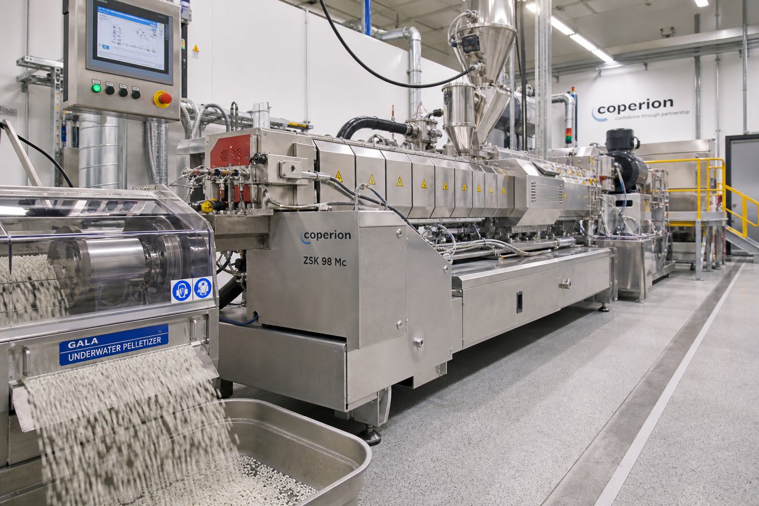
Key Industry Applications for Twin Screw Compounding Extruders
Knowing that a twin screw extruder mixes better, handles more feedstocks, and offers tighter process control than simpler alternatives is useful in theory. But the real proof is in what these machines actually produce. Across a surprisingly wide range of industries, twin screw extruders solve problems that no other continuous processing equipment can touch. The specific way each industry leverages the technology, however, varies dramatically.
Polymer Compounding and Masterbatch Production
Polymer compounding is, by volume, the single largest application for co-rotating twin screw extruders. The concept is straightforward: take a base resin and blend it with whatever additives are needed to create a material with the right mechanical, thermal, optical, or flame-retardant properties for a finished product. In practice, though, "straightforward" is the wrong word. A typical compounding formula might combine a polyolefin or engineering thermoplastic with mineral fillers like calcium carbonate or talc, glass fibers for structural reinforcement, UV stabilizers, antioxidants, flame retardants, impact modifiers, and processing aids, sometimes ten or more ingredients at once.
Why does this require a compounding twin screw extruder rather than a batch mixer or single screw machine? Because each of those additives has different particle sizes, densities, melting behaviors, and sensitivity to shear. Mineral fillers arrive as agglomerates that must be broken apart and wetted by the polymer matrix. Glass fibers need to be dispersed uniformly without being shattered into dust. Heat-sensitive stabilizers must be blended in quickly and gently. Only the modular screw configuration of a twin screw compounding extruder gives engineers the ability to stage these tasks sequentially along the barrel, applying aggressive kneading where dispersion demands it and gentler distributive mixing where fragile components need protection.
Masterbatch production takes this a step further. Imagine a manufacturer who needs to supply a consistent blue color concentrate to dozens of downstream processors, each running a different base resin. The masterbatch producer must disperse pigment particles at extremely high loading levels, sometimes 40 to 70 percent by weight, into a carrier resin. Achieving uniform color without streaks, specks, or agglomerates requires the kind of intensive dispersive mixing that only intermeshing co-rotating screws deliver. The compounded melt then passes through a die and into a screw extruder granulator setup, typically a strand pelletizer or underwater die-face cutter, that chops the output into uniform pellets ready for the customer's hopper.
This pelletizing step is so integral to the workflow that many compounding lines are defined by their downstream screw extruder granulator system as much as by the extruder itself. The pellet size, shape, and cooling rate all influence how the material behaves when it is remelted on the customer's single screw line for final shaping.
Reactive Extrusion, Recycling, and Pharmaceutical Applications
Compounding blends existing materials together. Reactive extrusion goes a step further: it uses the twin screw extruder as a continuous chemical reactor. Imagine running a polymerization reaction, a grafting reaction, or a controlled degradation process not in a stirred tank over several hours, but inside a barrel in under a minute. That is exactly what reactive extrusion achieves.
The co-rotating twin screw extruder is particularly well suited to this role because it handles the core challenges of reactive processing simultaneously. Research published in Mechanics & Industry highlights the key advantages: reactions proceed in bulk without solvents, devolatilization removes byproducts efficiently, the continuous process replaces slow batch methods, and the modular screw design allows engineers to sequence reaction and mixing steps within a single barrel. Common reactive extrusion processes include maleic anhydride grafting onto polyolefins for adhesion improvement, chain extension of polyesters and polyamides for molecular weight control, and in-situ synthesis of polymer blends through reactive compatibilization. The same research notes that corotating twin screw extruders have proven to be the most widely used platform in reactive extrusion, precisely because of their modular design and superior mixing characteristics.
One particularly compelling industrial example involves Thermoplastic Vulcanizates, where an elastomer phase is crosslinked in-situ during melt blending within a thermoplastic matrix. Reactive extrusion is the only technology that can simultaneously control the dispersion of the crosslinked rubber particles while maintaining the processability of the thermoplastic host, a feat that batch mixing simply cannot replicate.
Plastics recycling represents another rapidly growing application. Post-consumer waste streams are messy. They arrive contaminated with labels, adhesives, moisture, and mixed polymer species that would choke a single screw extruder. Twin screw machines handle these feeds because their self-wiping screws resist material buildup, their vacuum venting strips out moisture and volatile contaminants, and their modular screw configurations can be tuned to accommodate the unpredictable rheology of recycled feedstocks. Industrial recycling operations even combine reactive extrusion with recycling, using peroxides or other additives to adjust the viscosity and compatibility of mixed PP/PE waste streams during extrusion. The result, demonstrated in real-world production of automotive bumpers from post-consumer waste, is a high-quality compound that would be impossible to achieve without the twin screw platform.
In pharmaceuticals, the hot melt extruder has opened up entirely new approaches to drug delivery. Many drug candidates suffer from poor water solubility, which limits how much active ingredient the body can actually absorb. Hot-melt extrusion on twin screw platforms solves this by intimately dispersing the active pharmaceutical ingredient into a polymer carrier at elevated temperature, creating what is known as an amorphous solid dispersion. The drug molecules are trapped in a non-crystalline state within the polymer matrix, dramatically improving bioavailability. Commercial products like Kaletra (HIV treatment) and Noxafil (antifungal) are manufactured using this exact process. The twin screw extruder's tight residence time distribution is especially important here, because pharmaceutical APIs can degrade rapidly at processing temperatures if they linger too long in the barrel. Residence times of under one minute are common.
Food processing rounds out the application landscape. Twin screw extruders cook, texturize, and shape products ranging from breakfast cereals and snack puffs to pet food kibble and plant-based meat alternatives. The combination of high shear, precise temperature control, and the ability to inject water or steam at specific barrel locations gives food engineers the tools to transform raw starches and proteins into expanded, textured products with controlled density and crunch.
Here is a consolidated view of the major industries and how each leverages twin screw technology:
- Polymer compounding — blending resins with fillers, reinforcements, stabilizers, and colorants to produce engineered plastics and masterbatch concentrates
- Reactive extrusion — running grafting, polymerization, chain extension, and compatibilization reactions continuously inside the barrel
- Plastics recycling — reprocessing contaminated, mixed-polymer post-consumer waste with simultaneous devolatilization and viscosity adjustment
- Pharmaceuticals — creating amorphous solid dispersions and controlled-release formulations via hot melt extrusion to improve drug bioavailability
- Food processing — cooking, texturizing, and shaping cereals, snacks, pet food, and plant-based proteins through combined thermal and mechanical energy input
- Advanced materials — producing nanocomposites, conductive compounds, biodegradable polymers, and high-performance engineering blends
What connects all of these applications is a shared dependence on the twin screw extruder's ability to precisely control shear, temperature, residence time, and feed composition in a continuous process. The specific screw configuration, barrel layout, and operating parameters differ enormously from one application to the next, but the underlying platform remains the same.
That adaptability also raises a practical question: when you are evaluating a twin screw extruder for any of these applications, which technical specifications actually matter, and how do you translate a process that works on a small lab machine into a full-scale production line?
Key Specifications and Scale-Up Considerations for Twin Screw Extruders
A spec sheet for a twin screw extruder can feel like alphabet soup: L/D, RPM, Nm/cm³, kW. Each number describes something important about how the machine performs, yet none of them tells the full story in isolation. The real skill lies in understanding how these parameters interact, and why a number that looks ideal on paper can produce terrible results if the other specs are not aligned with it. Whether you are comparing machines on the market or trying to translate a successful lab trial into a production-scale operation, these are the specifications that deserve your attention.
Critical Specifications Every Buyer Should Understand
L/D ratio — the length-to-diameter ratio — is arguably the first number you will encounter and one of the most consequential. It describes how long the processing path is relative to the screw diameter. A higher L/D ratio gives material more barrel length to travel through, which means more room for additional functional zones: extra mixing sections, longer melting zones, multiple devolatilization stages, or side-feed ports for downstream filler introduction. Machines designed for simple blending tasks might use a moderate L/D, while demanding compounding or reactive extrusion processes often call for significantly higher ratios to accommodate the number of unit operations packed into a single barrel. The key tradeoff? Longer barrels increase residence time, which is beneficial for thorough mixing but risky for heat-sensitive polymers that degrade with prolonged thermal exposure.
Screw diameter directly governs throughput capacity. Larger diameters mean larger screw channel volumes, which translates to higher mass flow rates at equivalent screw speeds. But diameter is not just about volume. It also determines the scale of forces at play: the torque required to rotate the screws, the surface area available for heat transfer, and the shear rates generated in the nip region between intermeshing flights. Doubling the screw diameter does not simply double throughput — it changes the entire thermomechanical environment inside the barrel.
Maximum screw speed (RPM) controls shear rate, which in turn affects mixing intensity, melt temperature, and energy input. Higher RPM means more aggressive kneading, faster melting, and shorter residence time for any given fill level. Sounds like a win across the board? Not always. Pushing RPM too high on a shear-sensitive material can overheat the melt, degrade the polymer chain, or destroy delicate additives like long glass fibers. The optimal speed is always a compromise between mixing quality and thermal safety.
Torque density describes how much rotational force each screw can deliver per unit of cross-sectional area, often expressed in Nm/cm³. This specification sets the ceiling on how much mechanical energy the screws can transfer into the material. A machine with high torque density can process high-viscosity formulations, heavily filled compounds, and high-throughput operations without the gearbox becoming the bottleneck. When a process engineer says a machine "ran out of torque," they mean the motor and gearbox could not deliver enough energy to mix or convey the material at the target feed rate and RPM — one of the most frustrating limitations in production.
Number of barrel temperature zones determines how precisely operators can control the thermal profile along the machine's length. Each zone is independently heated and cooled, allowing different setpoints for the feed section, melting zone, mixing zone, venting section, and metering area. More zones mean finer thermal resolution, which becomes critical for processes involving reactive chemistry, heat-sensitive polymers, or multi-stage devolatilization. Fewer zones reduce hardware cost but limit your ability to tailor the temperature curve to the needs of complex formulations.
Here is the crucial insight: these specifications do not operate independently. They interact in ways that can either amplify or undermine each other.
- Increasing RPM raises shear rate, which generates more viscous heating inside the melt. If barrel cooling capacity is insufficient, the melt overheats regardless of what the temperature zone setpoints say.
- Increasing L/D provides more processing length, but it also increases total residence time. For a heat-sensitive biopolymer, the added mixing capability may come at the cost of thermal degradation.
- A larger screw diameter boosts throughput capacity, but the surface-area-to-volume ratio drops. Heat removal through the barrel wall becomes less efficient per kilogram of material, making thermal management harder at scale.
- Higher torque density enables more aggressive screw configurations, but only if the screw elements and barrel metallurgy can withstand the resulting mechanical stress without accelerated wear.
The best machine for any application is the one where all of these parameters are balanced against the specific demands of the material and process, not the one with the most impressive single number on the data sheet.
Scaling from Laboratory to Production
Almost every new twin screw extrusion process starts small. A lab extruder with a screw diameter in the range of 16 to 27 mm lets engineers develop formulations, test screw configurations, and establish baseline processing windows using just a few kilograms of material. A laboratory twin screw extruder is invaluable during this phase because it costs a fraction of a production machine to operate, consumes minimal raw material, and allows rapid iteration. You can trial ten different screw profiles in a single day, something that would be impossibly expensive and time-consuming on a full-scale line.
The challenge arrives when that successful lab trial needs to become a production reality on a machine with a screw diameter two, three, or even five times larger. Scaling up a twin screw extrusion process is not simply a matter of building a bigger version of the same machine. The physics change as dimensions grow, and what worked perfectly on a lab scale extruder can fail spectacularly at production scale if the transition is not handled carefully.
Three principles guide successful scale-up:
- Geometric similarity — the L/D ratio of the production machine should match the laboratory scale extruder as closely as possible. If the lab process was developed at an L/D of 40:1, the full-scale machine should maintain that same ratio. This ensures that the number and relative length of functional zones — feeding, melting, mixing, venting, metering — remain proportional. Research on counter-rotating twin screw extrusion scaling has confirmed that keeping the L/D ratio constant between reference and target machines is a foundational requirement for preserving process similarity.
- Matching specific energy input — specific energy, measured as energy per kilogram of throughput, captures the combined mechanical and thermal history the material experiences. If the lab scale twin screw extruder delivered a certain specific energy that produced ideal melt quality, the production machine must deliver the same value. This typically requires adjusting screw speed, feed rate, and barrel temperature profiles simultaneously, because the ratio of motor power to throughput shifts as diameter increases.
- Preserving residence time distribution — the distribution of how long individual material particles spend inside the extruder must remain as narrow and consistent as it was on the small machine. A wider residence time distribution on the production line means some material is underprocessed while other material is overcooked, leading to inconsistent product quality. Residence time distribution is influenced by fill fraction, screw speed, and the specific arrangement of conveying and mixing elements, all of which may need adjustment during scale-up.
A subtlety that trips up even experienced engineers is the surface-area-to-volume ratio problem. As screw diameter increases, the volume of material in each channel grows faster than the barrel surface area available for heat transfer. On a small lab extruder, barrel heating and cooling have an outsized influence on melt temperature because every particle of material sits close to a heated or cooled wall. On a large production machine, the core of the melt stream is farther from the barrel surface, so the material relies more heavily on viscous shear heating for energy input and less on conduction from the barrel. This shift means that screw element configurations often must be adjusted during scale-up — a kneading block arrangement that produced gentle mixing on a 26 mm machine may generate excessive shear heating on a 92 mm machine because the core material cannot shed heat to the barrel wall fast enough.
The practical implication is clear: screw profile translation is not one-to-one. Engineers frequently need to reduce kneading block aggressiveness, lengthen conveying zones, or modify stagger angles when moving from a laboratory twin screw extruder to a production platform. The scaling study by Nastaj and Wilczynski demonstrated this by showing that even when geometric similarity and operating conditions were carefully matched between a 34 mm reference extruder and a 51 mm target machine, barrel temperatures and screw speeds had to be independently optimized to minimize deviations in melt temperature and plasticating profiles.
Lab scale twin screw extruder trials remain indispensable not because they give you a production recipe you can copy directly, but because they establish the processing boundaries — the specific energy window, the thermal limits, the minimum mixing intensity needed for adequate dispersion — that inform how the production-scale screw profile and operating parameters should be set. Skipping the lab phase and going straight to production is a gamble that almost always costs more in wasted material, lost time, and suboptimal product quality than the laboratory work would have.
With a clear picture of what the specifications mean and how laboratory results translate to full-scale operations, the final piece of the puzzle is pulling all of this knowledge together into a practical framework for selecting the right twin screw extruder configuration, and the right component partners, for your specific application.
How to Choose the Right Twin Screw Extruder Machine
Specifications, screw element theory, and scale-up principles are valuable knowledge, but at some point, every manufacturer faces the same concrete question: which configuration do I actually buy? The answer is never one-size-fits-all. It depends on the intersection of your material, your process, your throughput targets, and your budget. Walking through a structured set of decision questions will narrow the field far more efficiently than browsing catalogs from twin screw extruder manufacturers and comparing numbers in isolation.
Decision Framework for Choosing the Right Configuration
Think of selection as a funnel. Each question eliminates options that do not fit, leaving you with a progressively smaller set of viable configurations. Here is a practical sequence that works whether you are sourcing your first twin-screw extruder machine or replacing an aging line:
- What material are you processing? Identify the base polymer or ingredient — thermoplastic, thermoset, food, pharmaceutical active. Document its melt temperature, thermal sensitivity, viscosity range, and any abrasive or corrosive additives in the formulation. A glass-fiber-reinforced nylon compound and a heat-sensitive biopolymer blend demand entirely different barrel metallurgy, screw element materials, and temperature control precision.
- What level of mixing intensity does the process require? Simple melt blending of two compatible polymers sits at one end of the spectrum. Dispersing nano-fillers or running a reactive grafting reaction sits at the other. Higher mixing demands push you toward co-rotating intermeshing configurations with aggressive kneading block sections, while gentler blending can sometimes be handled by distributive mixing elements alone.
- What throughput do you need now, and what will you need in three to five years? Screw diameter sets the throughput ceiling. Undersizing forces you to run at maximum capacity with no room for growth. Oversizing wastes capital and energy. Industry guidance from equipment selection frameworks suggests building in a 20 to 30 percent capacity margin above current requirements to accommodate market expansion without requiring a second machine.
- What is your budget for equipment and ongoing maintenance? Twin screw extruder price varies significantly based on screw diameter, L/D ratio, torque class, and automation level. A double screw extruder machine equipped for demanding engineering plastics with high-torque gearboxes and advanced control systems will cost substantially more than a standard compounding platform. However, the cheapest machine is rarely the most economical over a ten-year ownership horizon. Factor in energy consumption, screw and barrel replacement intervals, and downtime costs when comparing quotes.
- Do you need process versatility or dedicated production? If your product mix includes dozens of different formulations, a modular parallel co-rotating design with swappable screw elements and configurable barrel segments gives you maximum flexibility. If you are running a single PVC pipe formulation 24 hours a day, a dedicated conical counter-rotating machine optimized for that specific material and output profile delivers better value.
How do these answers map to configurations? The pattern is consistent across most applications:
- Co-rotating intermeshing — the default for compounding, masterbatch, reactive extrusion, devolatilization, pharmaceutical hot-melt extrusion, and recycling. Offers the widest operating window, best self-wiping behavior, and greatest screw configuration flexibility.
- Counter-rotating intermeshing — the natural fit for PVC pipe, profile, and sheet extrusion, and for highly filled compounds where high die pressure and gentle shear are priorities.
- Conical counter-rotating — purpose-built for powder processing with high compression needs, particularly dry-blend PVC, where the tapered geometry excels at material intake and progressive densification.
When evaluating a twin screw extruder for sale, request trial runs on your specific material. Reputable twin screw extruder manufacturers maintain application laboratories where you can test formulations on the actual machine platform before committing capital. This step alone can prevent the single most expensive mistake in equipment procurement: buying a machine that cannot handle your real-world feedstock under production conditions.
Partnering With the Right Screw Barrel Supplier
Selecting the right machine frame is only part of the equation. The screw elements and barrel segments are the components that actually touch your material, and their quality directly determines product consistency, energy efficiency, and how often you shut down for maintenance. A poorly manufactured kneading block with inconsistent flight clearances will leak flow, reduce mixing efficiency, and wear prematurely. A barrel liner with inadequate hardness will erode within months when processing glass-filled compounds.
This is why sourcing screw and barrel components from a supplier who understands the full range of extrusion applications matters as much as choosing the right extruder platform. A knowledgeable supplier does not just sell steel — they match metallurgy, surface treatments, and dimensional tolerances to the specific demands of each process, whether that is pipe extrusion, profile lines, sheet production, pelletizing, or post-consumer recycling.
For manufacturers, recycling plants, and technical teams moving from research into implementation, connecting with specialized screw barrel support providers is a practical next step. NANHAIYA's Plastic Extruder Machine and Screw Barrel Support page offers a resource for sourcing screw barrel components tailored to specific processing lines, covering applications from pipe and profile to sheet, pelletizing, and recycling extrusion. Having a component partner who can respond quickly with correctly specified replacement elements minimizes unplanned downtime and keeps your line running at peak performance.
Ultimately, the best twin-screw extruder manufacturer relationship is one that extends beyond the initial sale. The machine will evolve as your product mix changes, as materials shift, and as market demands grow. The suppliers who earn long-term partnerships are the ones who understand that reality and support it with application expertise, responsive component supply, and genuine process knowledge — not just competitive pricing on hardware.
Twin Screw Extruder FAQs
1. What is the difference between a co-rotating and counter-rotating twin screw extruder?
In a co-rotating twin screw extruder, both screws spin in the same direction, producing high shear, excellent self-wiping action, and superior dispersive and distributive mixing. This makes them ideal for polymer compounding, reactive extrusion, and masterbatch production. Counter-rotating extruders have screws turning in opposite directions, trapping material in C-shaped chambers that generate higher pressure with lower shear. They excel in PVC pipe and profile extrusion where gentle material handling and strong die pressure are priorities. Co-rotating designs dominate the market for versatility, while counter-rotating machines serve dedicated, pressure-intensive applications.
2. Why choose a twin screw extruder over a single screw extruder?
A twin screw extruder offers independent control over throughput, mixing intensity, and residence time, which a single screw machine cannot match because it couples all three variables to screw speed. Twin screw designs use positive displacement conveying and self-wiping geometry, enabling them to handle multi-component feedstocks, starve-fed operation, side feeding of fillers and liquids, and vacuum devolatilization. They are essential for compounding, reactive extrusion, recycling contaminated plastics, and pharmaceutical hot-melt extrusion. Single screw extruders remain the better choice for simpler, high-volume shaping tasks like film blowing or pipe extrusion using pre-compounded pellets where intensive mixing is unnecessary.
3. What industries use twin screw extruders and for what applications?
Twin screw extruders serve a wide range of industries. In plastics, they compound base resins with fillers, colorants, and reinforcements and produce masterbatch concentrates. Reactive extrusion uses them as continuous chemical reactors for grafting and polymerization. Recycling plants rely on them to reprocess contaminated post-consumer waste. Pharmaceutical manufacturers use hot-melt extrusion to create amorphous solid dispersions that improve drug bioavailability. Food processors cook, texturize, and shape cereals, snacks, and pet food. Precision-engineered screw and barrel components from providers like NANHAIYA (https://www.nhyscrews.com/products/plastic-extruder-machine) help these operations maintain consistent quality across pipe, profile, sheet, pelletizing, and recycling lines.
4. How do you scale up a twin screw extrusion process from lab to production?
Successful scale-up follows three core principles: maintaining geometric similarity by keeping the L/D ratio constant between the lab extruder and the production machine, matching specific energy input so the material receives the same mechanical and thermal history per kilogram, and preserving a narrow residence time distribution for consistent product quality. Engineers must also account for the surface-area-to-volume ratio change as screw diameter grows. Larger machines remove heat less efficiently per kilogram through the barrel wall, so screw element configurations often need adjustment, such as reducing kneading block aggressiveness, to prevent overheating. Lab-scale trials remain essential for establishing processing boundaries before committing to full-scale production.
5. What are the most important specifications when buying a twin screw extruder?
Five specifications matter most. L/D ratio determines how many functional zones fit along the barrel, with higher ratios supporting complex compounding or reactive extrusion. Screw diameter governs throughput capacity. Maximum screw speed (RPM) controls shear rate and mixing intensity. Torque density sets the ceiling on mechanical energy the screws can transfer, which is critical for high-viscosity or heavily filled formulations. The number of barrel temperature zones dictates how precisely the thermal profile can be managed. These parameters interact, so the best machine is one where all specs are balanced against specific material and process demands rather than optimized for a single impressive number.
Written by
Nanhaiya Technical Team
Zhoushan Nanhaiya Plastic Machinery Co., Ltd.
The Nanhaiya technical team supports screw and barrel manufacturing projects through application review, technical communication, custom manufacturing coordination, and production and quality control.
Discuss Your Application
Related Articles
More insights on screw barrel technology and plastics processing.

Extruder Machine Decoded: From Raw Pellet To Finished Product
Oct 6, 2026
Learn how an extruder machine works, compare single-screw vs. twin-screw types, and get expert guidance on specs, troubleshooting, and selection.
Read Article
PE Pipe Making Machine Decoded: From Raw Resin to Flawless Pipe
Oct 4, 2026
Learn how a PE pipe making machine works, from resin to finished pipe. Covers components, material grades, automation, troubleshooting, and buyer selection tips.
Read Article
PVC Profile Making Machine Decoded: From Raw Resin To Profit
Oct 3, 2026
Learn how a PVC profile making machine works — extrusion process steps, key technical parameters, die design, calibration methods, maintenance, and total cost of ownership.
Read ArticleLooking for something else?
Search by material, symptom or product and jump straight to the relevant page.
These are navigation suggestions based on keyword matching — not a quotation, not a delivery commitment, and not a substitute for engineering review. Final specification is confirmed by our engineers against your drawings and processed material.
Need help with screw barrel selection?
Share your machine model, processed material and application. Our team can help with pricing and technical support.