

What Is a Twin Screw Extruder and Why Types Matter
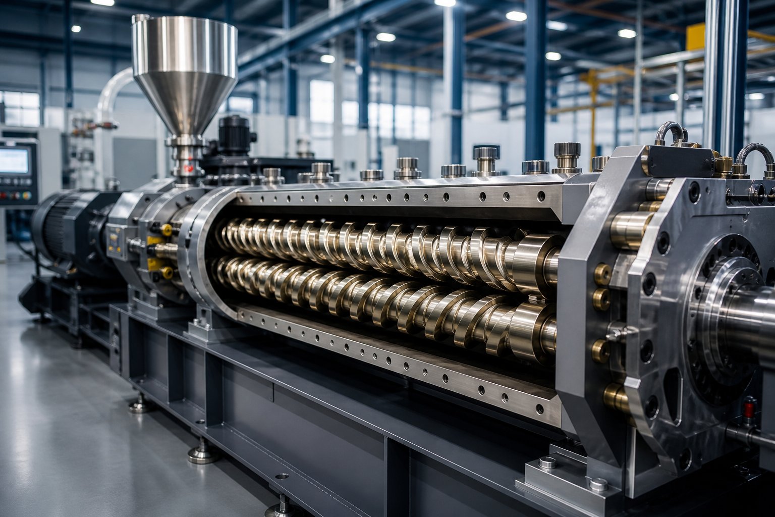
Imagine two screws spinning side by side inside a heated barrel, working together to grab raw material, melt it, blend it, and push it into a finished shape. That, in essence, is what a twin screw extruder does. Yet the way those two screws interact with each other varies dramatically from one machine to the next, and that variation changes everything about how your material behaves during processing.
Defining the Twin Screw Extruder
A twin screw extruder is a polymer and materials processing machine that uses two co-acting screws, rotating inside a closely fitted barrel, to convey, melt, mix, and pressurize raw materials into a controlled output. The screws may intermesh or operate tangentially, rotate in the same or opposite directions, and follow parallel or tapered geometries, giving rise to distinct extruder types suited to different process demands.
This definition hints at something important: there is no single twin-screw extruder design. Instead, you'll encounter a family of configurations, each engineered around a specific combination of rotation direction, intermeshing degree, and screw geometry. A screw extruder built for gentle PVC pipe processing looks and operates very differently from one designed for high-intensity polymer compounding.
Why Classification Matters for Engineers and Processors
Selecting the wrong twin screw configuration leads to real consequences. Poor dispersive mixing, excessive thermal degradation, throughput bottlenecks, or inadequate pressure at the die are all symptoms of a mismatch between extruder type and process requirement. Each configuration produces its own mixing intensity, residence time distribution, and pressure profile. Understanding these differences is not academic; it is the foundation of sound equipment selection.
A bit of history helps explain why so many types exist. Counter-rotating designs appeared first, developed primarily in the 1960s to handle heat-sensitive PVC, which demanded gentle, controlled conveying. Co-rotating intermeshing machines followed as the compounding industry grew, offering high-speed, self-wiping action ideal for engineering plastics and masterbatch production. Over decades, the twin screw platform branched into parallel, conical, tangential, and laboratory-scale variants, each answering a specific processing challenge.
The result is a rich but sometimes confusing landscape of machine types. What separates one from another, and how do you match design to process? That question hinges on three classification axes that, when combined, define every twin screw extruder configuration on the market.
A Hierarchical Framework for Classifying Twin Screw Extruders
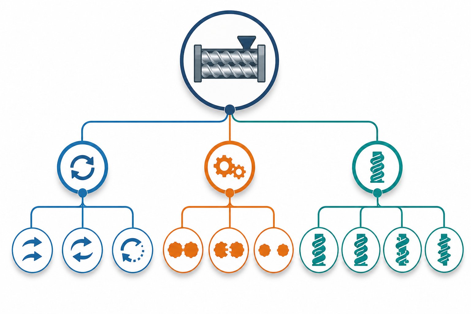
Most guides list twin screw extruder types as if they exist in isolation: co-rotating here, conical there, intermeshing somewhere else. That flat-list approach hides the real logic behind the classification. In practice, every twin screw extruder you encounter sits at the intersection of three independent design decisions. Think of these as classification axes. Once you understand each axis, you can systematically decode any configuration rather than memorizing disconnected categories.
Three Classification Axes for Twin Screw Extruders
Every twin-screw extruder on the market can be described by answering three questions. Each question represents one axis of the classification framework:
- Axis 1 - Rotation Direction: Do the two screws rotate in the same direction or in opposite directions?
- Co-rotating - Both screws turn the same way (both clockwise or both counterclockwise).
- Counter-rotating - One screw turns clockwise while the other turns counterclockwise.
- Axis 2 - Intermeshing Degree: How closely do the flights of one screw engage with the channels of the other?
- Closely (fully) intermeshing - The flight of one screw reaches deep into the channel of the other, leaving minimal clearance. This tight engagement drives strong mechanical interaction and enables self-wiping in co-rotating designs or positive displacement conveying in counter-rotating designs.
- Tangential / loosely intermeshing - The screws sit with a larger gap between them. They still influence each other's flow field but without the tight mechanical engagement of a fully intermeshing pair.
- Non-intermeshing - The distance between shaft centers equals or exceeds the sum of the outer radii. Each screw operates essentially independently, reducing shear forces significantly.
- Axis 3 - Screw Geometry: Are the screws cylindrical from feed to discharge, or do they taper?
- Parallel - Both screw diameter and center-to-center distance remain constant along the full barrel length, providing uniform shear distribution and allowing greater design freedom for processing zones.
- Conical - Screws taper from a larger diameter at the feed end to a smaller diameter at the discharge end, naturally creating a compression zone that builds pressure as material moves forward.
Mathematically, combining two rotation options, three intermeshing options, and two geometry options produces twelve theoretical permutations. In reality, the market uses far fewer because some combinations offer no practical advantage or are mechanically impractical. Understanding which combinations dominate - and why - is far more useful than memorizing all twelve.
How Classification Axes Combine Into Real Configurations
When you layer these three axes on top of each other, specific twin screw extruders emerge as distinct configurations. The table below maps the most commercially relevant combinations, linking each one to its defining characteristics and where you'll typically find it on a production floor:
| Rotation Direction | Intermeshing Degree | Screw Geometry | Common Name | Primary Application |
|---|---|---|---|---|
| Co-rotating | Closely intermeshing | Parallel | Standard compounding extruder | Polymer compounding, masterbatch, reactive extrusion |
| Counter-rotating | Closely intermeshing | Conical | PVC profile / pipe extruder | Rigid PVC pipe, window profiles, WPC decking |
| Counter-rotating | Closely intermeshing | Parallel | Parallel counter-rotating extruder | PVC pipe, calendar feeding, specialty compounding |
| Counter-rotating | Tangential / non-intermeshing | Parallel | Tangential counter-rotating extruder | Devolatilization, chemical reactions, specialty polymers |
| Co-rotating | Closely intermeshing | Parallel (lab scale) | Laboratory / benchtop extruder | Formulation R&D, small-batch trials, academic research |
Notice a pattern: co-rotating twin screw extruders are almost always closely intermeshing and parallel. That pairing unlocks the self-wiping, high-speed mixing behavior the compounding industry demands. Counter-rotating screw extruders, by contrast, appear across a wider spread of intermeshing degrees and geometries because they serve diverse needs - from gentle PVC conveying to high-volume devolatilization.
This framework gives you a practical decoding tool. The next time you encounter a machine described as a "co-rotating parallel twin screw" or a "counter-rotating conical," you can instantly locate it on these three axes and predict its core behavior: mixing intensity, pressure capability, conveying mechanism, and likely application. The real engineering question is what happens inside each of these configurations at a process level - starting with the one that dominates modern compounding: the co-rotating intermeshing design.
Co-Rotating Intermeshing Twin Screw Extruders
Why has one particular configuration become the default choice for polymer compounding worldwide? The answer lies in a deceptively simple kinematic principle: make both screws turn the same way, mesh them tightly together, and let geometry do the rest. The co-rotating intermeshing twin screw extruder creates a processing environment that no other configuration can replicate - one that combines aggressive mixing, continuous self-cleaning, and extraordinary flexibility within a single machine platform. Understanding how it works reveals why it dominates.
The Self-Wiping Mechanism Explained
Picture two closely intermeshing screws rotating in the same direction inside a figure-eight-shaped barrel bore. As they spin, the flight tip of one screw sweeps across the root of the adjacent screw with minimal clearance. This tight engagement scrapes material off every metal surface, preventing anything from sticking, stagnating, or degrading on the screw walls.
Here is where the magic happens. Because both screws rotate the same way, material trapped in the channel of one screw gets intercepted by the advancing flight of the other screw and transferred across the intermeshing zone to the opposite channel. Then it gets pushed forward, crosses back over at the next intermeshing region, and repeats. If you could trace the path of a single polymer pellet through the barrel, you would see it tracing a continuous figure-eight pattern - looping from one screw to the other while simultaneously traveling from the feed port toward the die.
This figure-eight flow path achieves two things simultaneously. First, the constant surface renewal prevents stagnant pockets where heat-sensitive material might sit and degrade into burned specks or discolored particles. Second, the repeated cross-channel transfer ensures that every particle experiences nearly the same thermal and shear history. In technical terms, the co rotating twin screw extruder produces an exceptionally narrow residence time distribution. Almost all material spends roughly the same amount of time inside the machine, which is critical for applications like reactive extrusion where under-reacted and over-reacted material both mean rejected product.
The wiping action also delivers a practical operational benefit that production teams appreciate: dramatically faster color changes and material transitions. Because degraded polymer cannot accumulate on screw surfaces, purge times drop significantly compared to single screw or counter-rotating machines. A well-designed co-rotating system can run for extended production campaigns without needing to be pulled apart for cleaning.
Advantages and Limitations of Co-Rotating Extruders
No machine is perfect for every job. The co-rotating design brings powerful strengths to compounding and mixing-intensive processes, but it also carries trade-offs that engineers must weigh. Here is a clear breakdown:
Pros
- Superior distributive and dispersive mixing: Specialized kneading block elements create high-shear and elongational flow zones that break apart pigment agglomerates, filler clumps, and immiscible polymer domains. Mixing intensity is adjustable by changing kneading disc stagger angles - 30-degree offsets for gentle blending, up to 90 degrees for maximum shear.
- Self-cleaning operation: The wiping action between flights and channels eliminates dead zones, reducing degradation risk and enabling cleaner transitions between products.
- High throughput potential: Co-rotating machines can operate at significantly higher screw speeds than counter-rotating designs - often reaching 300 to 1,000 RPM depending on screw diameter. Higher speed translates directly into greater volumetric output per unit of screw size.
- Modular screw design: Segmented screw elements slide onto a splined shaft, letting engineers rearrange conveying elements, kneading blocks, and mixing elements to tailor the screw profile for each formulation. A single machine can handle dozens of different recipes.
- Narrow residence time distribution: The self-wiping figure-eight flow ensures uniform thermal history, which is essential for heat-sensitive engineering resins and reactive compounding processes.
- Excellent devolatilization: The positive conveying action and constant melt surface renewal make co-rotating designs highly effective at removing moisture, monomers, and volatile byproducts under vacuum.
Cons
- Lower pressure generation: Compared to counter-rotating closely intermeshing designs, co-rotating machines generate less die-head pressure. Applications requiring very high discharge pressures - such as direct extrusion of thick-walled PVC profiles - may need additional melt pump support.
- Higher capital cost: The precision gearbox, segmented barrel system, and modular screw elements make co-rotating extruders more expensive to purchase than comparable counter-rotating or single screw machines.
- Sensitivity to screw element configuration: The very flexibility that makes modular screws powerful also means a poorly designed screw profile can cause surging, insufficient mixing, or excessive melt temperature. Getting the configuration right demands process expertise.
Why Co-Rotating Extruders Dominate Compounding
Walk into any modern compounding facility producing engineering plastics, color masterbatch, filled compounds, or thermoplastic elastomers, and you will almost certainly find a co-rotating intermeshing parallel twin screw extrusion line at its core. This dominance is not accidental. It stems from two features that align perfectly with what compounders need: modularity and material-safe processing.
The modular screw element system is arguably the single most important innovation behind the co-rotating platform's success. Rather than committing to a fixed screw geometry, processors assemble custom screw profiles from an inventory of standardized elements - forward-pitch conveying segments for transport, reverse-pitch elements for building pressure or creating melt seals, and kneading blocks of varying disc widths and stagger angles for tuning shear intensity. A twin screw compounding extruder built this way can be reconfigured in a matter of hours to switch from dispersing carbon black in polyethylene to blending glass fiber into nylon - without purchasing a new machine.
This adaptability is especially valuable in job shops and custom compounding operations that run many different formulations. A single compounding extruder platform handles everything from high-filler-loading mineral compounds to low-viscosity reactive systems simply by rearranging the screw profile and adjusting process parameters. Counter-rotating and conical machines, by contrast, frequently use monolithic one-piece screws that lock in a single processing behavior.
The self-wiping behavior adds a second, equally important advantage. Engineering resins like polycarbonate, polyamide, and PET are sensitive to extended heat exposure. Stagnant material degrades into gels, black specks, or discolored particles that ruin product quality. Because a co-rotating twin screw compounding extruder continuously scrapes its own surfaces, these heat-sensitive resins can be processed with confidence that thermal history remains uniform and brief. The same principle makes the platform ideal for reactive extrusion, where grafting reactions, polymerizations, or chain-extension chemistry demand tight control over how long material stays at elevated temperatures.
Taken together, modularity and self-wiping explain why twin screw extrusion on the co-rotating platform captured the compounding market so thoroughly. Yet co-rotating machines are only one side of the story. The very limitations just described - particularly in pressure generation and gentle low-speed conveying - point directly to applications where counter-rotating designs hold a clear advantage.
Counter-Rotating Twin Screw Extruders
Pressure generation and gentle, controlled conveying are exactly what heat-sensitive materials demand. Counter-rotating twin screw extruders deliver both by reversing a fundamental kinematic relationship: instead of spinning in the same direction, the twin screws rotate in opposite directions. That single change transforms the entire flow field inside the barrel, creating a conveying mechanism that is fundamentally different from the co-rotating approach - and ideally suited to an entirely different class of applications.
Operating Principle and Calendering Action
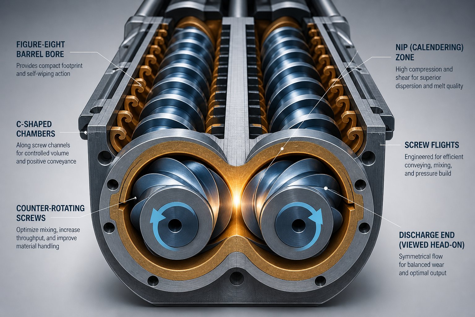
Imagine two rollers in a printing press or a rubber mill, turning toward each other and squeezing material through the narrow gap between them. That is essentially the calendering action that occurs in a counter-rotating twin screw extruder. As the twin screws rotate in opposite directions, their surfaces move in the same direction at the intermeshing zone, dragging material into the narrowing gap - the nip region - between the core of one screw and the flight tip of the other.
This squeeze-flow dynamic generates substantial localized pressure. Research on a 55 mm parallel twin screw extruder measured pressure differences of 4.7 to 7.1 MPa between upstream and downstream positions around the barrel near the nip, with separating forces exceeding one metric ton acting on the screws during rigid PVC processing. These forces are large enough to deflect the screws toward the barrel wall, which is why closely intermeshing counter-rotating machines typically run at lower rotational speeds than their co-rotating counterparts.
The real magic of counter-rotation, though, lies in what happens along the screw length. Because the flights of one screw penetrate the channels of the other, the material becomes trapped in helically distorted C-shaped chambers - enclosed pockets formed between successive flight tips, the screw root, and the barrel wall. These chambers do not open into each other the way channels do in a co-rotating design. Instead, each chamber acts like an individual bucket on a conveyor belt, carrying its payload forward from feed to discharge with minimal leakage.
This is what engineers call positive displacement conveying. The output of a closely intermeshing counter-rotating extruder is nearly proportional to screw speed and almost independent of die resistance. You'll notice this stands in sharp contrast to co-rotating machines, where drag flow and pressure flow interact and throughput varies with back pressure. For materials that need predictable, low-shear transport - where you want to move material forward without subjecting it to intense mixing - positive displacement is a decisive advantage.
Closely Intermeshing vs. Tangential Counter-Rotating Designs
Not all counter-rotating extruders work the same way. The degree of intermeshing creates two fundamentally different machines, each optimized for distinct processing goals. Treating them as interchangeable is a common mistake.
- Closely intermeshing counter-rotating: The flights of one screw engage deeply into the channels of the other, leaving only small calender gaps (often under 1 mm), screw-barrel clearances around 0.1 mm, and narrow flank gaps. This tight geometry creates well-sealed C-shaped chambers that deliver true positive displacement pumping. Material transport depends almost entirely on screw rotation rather than viscous drag. These machines run at relatively low screw speeds - large-diameter production units are often limited to below 50 RPM to manage the enormous separating forces generated in the nip. They are the standard choice for PVC pipe, profile, and sheet screw extrusion, where gentle handling and predictable output are non-negotiable.
- Tangential (loosely intermeshing or non-intermeshing) counter-rotating: Here the inter-screw gap is substantially wider. The screws still rotate in opposite directions, but without the tight sealing that creates closed C-chambers. This sacrifices the positive displacement characteristic but unlocks a major benefit: the machine can run at much higher rotational speeds without generating destructive separating forces. Higher speeds mean greater throughput and more energy input, making tangential configurations well suited for devolatilization, reactive processing, and specialty applications where extended residence time and large free volume are more important than gentle conveying. The broader residence time distribution of tangential designs is acceptable - even desirable - in applications like solvent removal, where longer exposure under vacuum improves mass transfer efficiency.
In short, closely intermeshing counter-rotating machines prioritize precision and gentleness; tangential designs trade that precision for speed and volume. Both fall under the counter-rotating umbrella, yet they serve very different roles in a processing operation.
Why Counter-Rotating Designs Excel with PVC
Rigid PVC presents one of the toughest challenges in polymer processing. Its decomposition temperature sits dangerously close to its processing temperature, it exhibits poor melt flow, and excessive shear generates frictional heat that accelerates degradation. A co-rotating extruder's high-shear, high-speed mixing environment - its greatest strength with engineering plastics - works against the process when rigid PVC is the feedstock.
The closely intermeshing counter-rotating parallel twin screw extruder solves this problem elegantly. Operating at high fill levels and low rotational speeds, it conveys PVC powder through sealed C-shaped chambers with minimal shear input. The calendering effect between the screws provides gentle dispersive mixing of additives like calcium carbonate, stabilizers, and impact modifiers - enough to achieve a homogeneous blend without generating the aggressive shear fields that would overheat and degrade the compound. As specialists in extrusion processing have noted, this approach allows the extrusion temperature to remain low while still achieving stable forming of pipes, sheets, and profiles.
This is precisely why PVC processing and counter-rotating technology have been linked since the early days of twin screw development. The combination of positive displacement conveying, low frictional heating, and controlled compressive mixing creates the exact thermal environment that PVC demands.
Key Advantages and Limitations
Like every extruder configuration, counter-rotating designs bring clear strengths alongside inherent trade-offs. Here is what you should weigh:
Pros
- Positive displacement conveying: Output is nearly proportional to screw speed and largely independent of die back pressure, providing predictable throughput for downstream processes.
- Low shear and frictional heating: Enclosed C-chambers move material with minimal mechanical energy input, making these machines ideal for thermally sensitive polymers like rigid PVC, CPVC, and certain bio-based resins.
- Excellent pressure generation: The sealed-chamber mechanism builds high discharge pressures efficiently, which is critical for direct extrusion through complex profile dies without auxiliary melt pumps.
- Effective dispersive mixing via calendering: The compressive and elongational deformation at the nip region disperses additives and fillers under gentle conditions - sufficient for PVC formulations where moderate dispersion outperforms aggressive high-shear mixing.
- Proven reliability for PVC forming: Decades of industrial refinement have made closely intermeshing counter-rotating extruders the mature, well-understood platform for rigid PVC pipes, window profiles, siding, and decking.
Cons
- Lower maximum screw speed: The large separating forces generated in the calender gap limit rotational speed. Production-scale closely intermeshing machines often stay below 150 RPM, and large-diameter units may be restricted to under 50 RPM. This caps maximum throughput relative to co-rotating designs of comparable screw diameter.
- Greater wear in the intermeshing zone: The calender forces push the twin screws toward the barrel wall, concentrating abrasive wear at predictable locations - typically between the 30-degree and 60-degree positions from vertical. This wear pattern demands harder barrel linings and periodic screw replacement.
- Limited mixing intensity: Positive displacement inherently means limited mixing. While the calendering action provides adequate dispersion for PVC compounds, it cannot deliver the intensive distributive and dispersive mixing that engineering plastics and nanocomposites require.
- Less modular screw design: Many counter-rotating extruders - especially conical models - use one-piece or limited-segment screw designs rather than the fully modular, segmented shafts common in co-rotating machines. This reduces process flexibility and makes reconfiguration more difficult.
- Narrower application range: The inherent speed and mixing limitations confine closely intermeshing counter-rotating machines primarily to PVC and similar low-shear applications, whereas co-rotating platforms serve a much broader material portfolio.
These limitations explain why the industry did not settle on a single twin screw design. Counter-rotating machines carved out a dominant position in PVC and certain specialty processes, while co-rotating machines captured compounding and reactive extrusion. Some applications, however, fall outside both of these mainstream platforms - which is where specialized variants like conical geometry, laboratory-scale systems, and reciprocating designs enter the picture.
Conical, Laboratory, and Other Specialized Twin Screw Extruder Variants
Not every processing challenge fits neatly into the co-rotating or parallel counter-rotating categories. Some applications demand a more compact footprint with exceptional pressure output. Others require only grams of material to test a new formulation. And a few niche processes need screw motion that goes beyond simple rotation. These edge cases gave rise to three specialized variants - conical, laboratory-scale, and reciprocating twin screw extruders - that round out the full spectrum of available configurations.
Conical Twin Screw Extruders for Compact High-Pressure Output
Imagine taking two counter-rotating intermeshing screws and gradually shrinking their diameter from the feed end to the discharge end. That is the core idea behind a conical twin screw extruder. The screws start with a large diameter at the hopper - creating a wide feed opening that readily accepts bulky powders and dry blends - and taper down to a noticeably smaller diameter at the exit. This geometry does something clever: it naturally compresses the material as it moves forward, building discharge pressure without relying on restrictive screw elements or separate melt pumps.
The taper also allows the gearbox to sit behind the larger end of the screws, where wider shaft spacing accommodates robust bearings and higher torque transmission. This gives conical designs a mechanical advantage that parallel configurations cannot match at equivalent screw lengths. The result is a surprisingly compact twin screw extruder machine that packs high torque and strong pressure generation into a small physical envelope.
In practice, conical designs are almost exclusively counter-rotating and closely intermeshing. That combination pairs the gentle, positive-displacement conveying behavior discussed in the previous section with the built-in compression of the tapered geometry. You'll find these machines dominating PVC window profile lines, rigid PVC pipe production, WPC (wood-plastic composite) decking extrusion, and foam board manufacturing - all applications where heat-sensitive material must be conveyed gently, compressed predictably, and pushed through complex dies at stable pressure.
The trade-off? Limited scalability. Because the taper constrains channel volume at the discharge end, conical extruders face practical throughput ceilings at larger sizes. Manufacturers needing very high output rates for PVC pipe, for example, sometimes shift to parallel counter-rotating machines that can scale to larger screw diameters without the geometric constraints imposed by converging screw geometry.
Laboratory and Benchtop Twin Screw Extruders
What if you only have 20 grams of a new API-polymer blend to test? Or you need to screen a dozen filler loadings before committing to a production trial? This is where the laboratory twin screw extruder earns its place. These scaled-down machines - typically co-rotating intermeshing with screw diameters ranging from about 5 mm to 20 mm - allow formulation scientists and process engineers to evaluate materials at a fraction of the cost and time a production run would require.
A benchtop twin screw extruder can process batch sizes as small as 5 to 25 grams, making it invaluable for early-stage screening of drug-polymer solid dispersions in pharmaceutical development, new color concentrate formulations, or experimental nanocomposite blends. As pharmaceutical researchers have noted, benchtop extruders expose material to shorter residence times and lower thermal stress than batch mixers, producing more representative samples of what a continuous process would deliver.
Here is the critical caveat that many equipment guides skip entirely: benchtop results do not scale up directly. The fundamental equipment-design attributes of a small laboratory extruder differ from those of a production machine. The surface-area-to-volume ratio is much higher in a small barrel, meaning heat transfer from the barrel wall dominates the melt temperature profile in ways it does not on a 50 mm or 75 mm production unit. Residence time distributions shift, shear rate profiles change nonlinearly, and the fill behavior of small-diameter channels differs from larger ones.
Successful scale-up typically requires an intermediate step. Mid-size extruders in the 12 to 20 mm range, sharing the same OD/ID screw geometry ratios as their larger production counterparts, bridge the gap between benchtop screening and full-scale manufacturing. Skipping this intermediate step - jumping directly from a 5 mm lab unit to a 40 mm production line - risks discovering that the process window identified in the lab simply does not translate. Mass-transfer and heat-transfer limitations at larger scales can require longer process sections, modified screw designs, or lower screw speeds that alter the residence time distribution of the material entirely.
Reciprocating Twin Screw Extruders
The least common variant in this family adds a second axis of motion. In a reciprocating (or oscillating) twin screw extruder, the screws not only rotate but also oscillate axially - moving back and forth along their length during operation. This axial pulse creates additional mixing and pressure-building action beyond what rotation alone can achieve.
Reciprocating designs occupy a narrow but important niche: injection molding compounding, where the extruder must plasticize, mix, and meter material in discrete shots rather than a continuous stream. The axial oscillation helps ensure thorough homogenization within the limited barrel length available on an injection unit. You'll also encounter this concept in certain specialized reactive processing and direct compounding-injection applications where inline blending of additives or reinforcements must happen immediately before mold filling.
Because production volumes for reciprocating units are small compared to continuous extrusion lines, this variant receives less attention in the industry literature. Yet for operations that need to compound and mold in a single integrated step, it eliminates the pelletizing stage entirely - a meaningful cost and energy advantage in the right context.
Comparing Conical, Laboratory, and Reciprocating Variants
The table below places these three specialized configurations side by side, highlighting where each fits within the broader twin screw landscape:
| Parameter | Conical Twin Screw Extruder | Laboratory / Benchtop Twin Screw Extruder | Reciprocating Twin Screw Extruder |
|---|---|---|---|
| Screw Geometry | Tapered (large feed diameter to small discharge diameter) | Parallel, constant diameter (typically 5-20 mm) | Parallel, with axial oscillation superimposed on rotation |
| Rotation Direction | Counter-rotating (almost exclusively) | Co-rotating intermeshing (most common) | Co-rotating or counter-rotating, depending on design |
| Primary Application | PVC pipe, profiles, WPC decking, foam board | Formulation R&D, small-batch production, academic research | Injection molding compounding, direct compounding |
| Typical Scale | Production (medium to high throughput) | Lab to pilot (grams to a few kg/h) | Production (shot-based, not continuous) |
| Key Advantage | Compact footprint, high torque, natural compression | Minimal material consumption, rapid formulation screening | Combines compounding and molding in one step |
| Key Limitation | Limited scalability at very high throughputs | Results do not scale directly to production extruders | Narrow application niche, limited commercial availability |
| Screw Modularity | Usually one-piece or limited-segment screws | Modular segmented elements on splined shafts | Varies by manufacturer; often limited modularity |
Each of these variants fills a gap that mainstream co-rotating and counter-rotating parallel machines leave open. Conical extruders deliver compact pressure for PVC forming. Laboratory units enable low-volume R&D screening. Reciprocating designs merge compounding with injection molding. Together with the co-rotating and counter-rotating platforms covered earlier, they complete the picture of what the twin screw extruder family offers.
Yet hardware alone only tells half the story. The real versatility of modern twin screw systems - especially co-rotating platforms - comes from what sits on the screw shafts and inside the barrel housings: modular elements that can be rearranged to create entirely different processing profiles within the same machine frame.
Modular Screw Elements and Barrel Design Across Extruder Types
Strip away the motor, gearbox, and control panel, and what really defines the processing behavior of a twin screw extruder is the arrangement of individual elements sitting on the screw shafts. This modular element system is the engineering innovation that turned co-rotating intermeshing machines into the most flexible processing platform in the polymer industry. It is also the design feature that most sharply separates one type of twin screw extruder from another in terms of day-to-day operational versatility.
Conveying, Kneading, and Mixing Elements
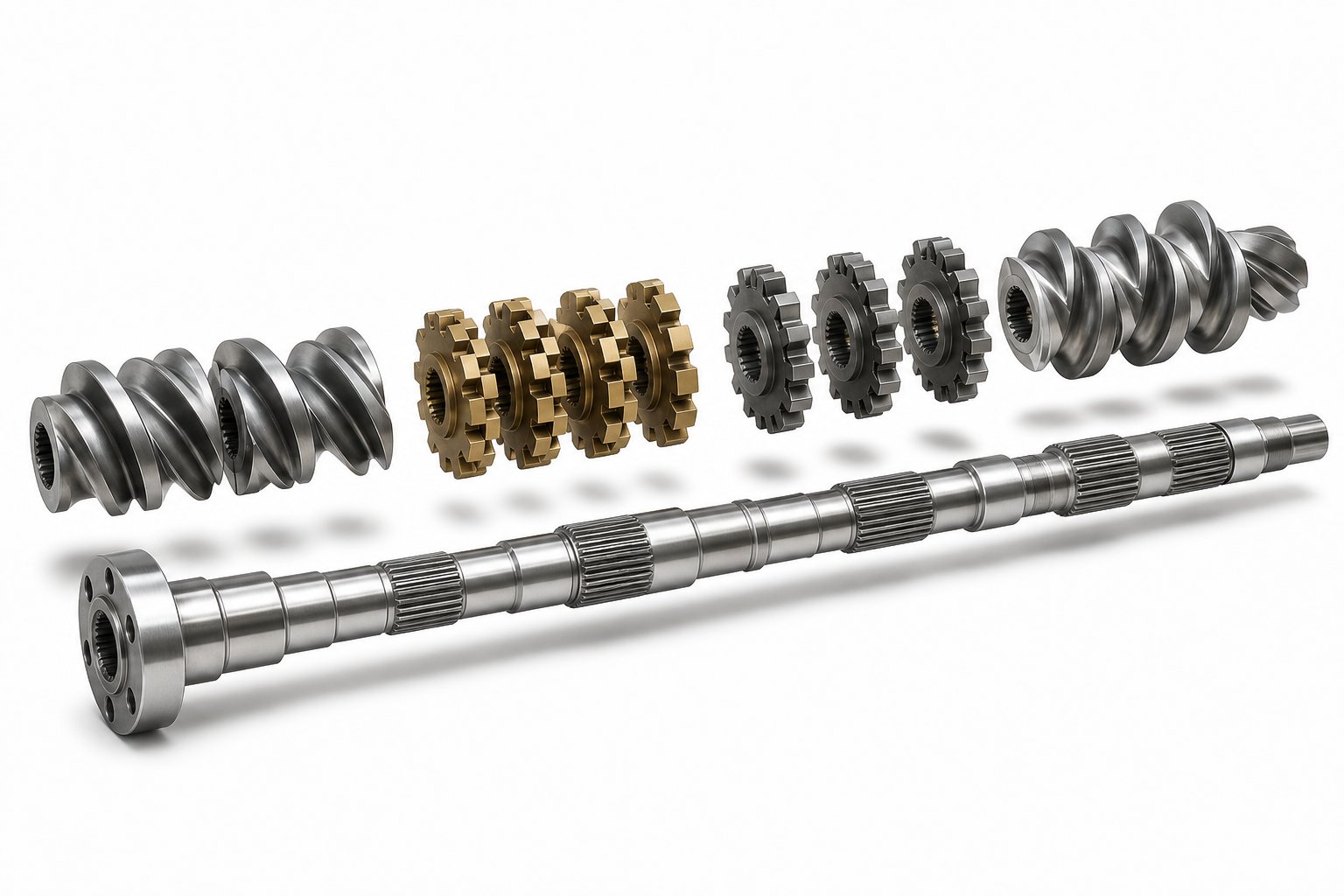
Every extruder screw profile on a modular twin screw machine is assembled from three fundamental categories of elements, each serving a distinct role in material transformation. Think of them as building blocks: you select, sequence, and combine them along a splined shaft to create a custom processing recipe without ever machining a new screw.
- Conveying elements look like traditional helical screws with defined pitch and flight depth. Forward-pitch versions transport material toward the die, while reverse-pitch versions intentionally push material backward, creating localized pressure buildup and melt seals upstream of vent ports or mixing zones.
- Kneading blocks are stacks of individual discs offset at specific stagger angles. Narrow discs at steep angles (60 to 90 degrees) generate intense shear for dispersive mixing - breaking apart pigment agglomerates or filler clusters. Wider discs at shallow angles (30 degrees) produce gentler distributive mixing, spreading components evenly without excessive energy input.
- Specialized mixing elements include toothed or gear-type geometries that repeatedly split and recombine the melt stream. These elements excel at distributive blending while strictly limiting temperature rise - a valuable trait when processing heat-sensitive formulations.
The table below maps these element categories to their function and typical position within a screw profile:
| Element Type | Sub-Variants | Primary Function | Typical Position Along Screw Profile |
|---|---|---|---|
| Conveying elements | Forward pitch (coarse, medium, fine); Reverse pitch | Material transport, pressure generation, melt sealing | Feed zone, between mixing sections, metering zone near die |
| Kneading blocks | Narrow disc / high stagger (dispersive); Wide disc / low stagger (distributive); Neutral (90-degree) | Melting, dispersive and distributive mixing, deagglomeration | Plasticizing zone, primary mixing zone, secondary mixing zone |
| Specialized mixing elements | Toothed / gear mixers, comb elements, interrupted-flight elements | Low-shear distributive blending, flow splitting and recombination | Final homogenization zone, downstream of high-shear sections |
| Reverse / back-conveying elements | Reverse-pitch conveying, reverse kneading blocks | Pressure seal creation, increased fill and residence time upstream | Before vent openings, before side-feed ports |
By sliding these elements on and off the splined shaft, an engineer can transform a plastic extruder screw from a gentle conveying profile into an aggressive compounding configuration in a matter of hours. One machine handles color masterbatch in the morning and glass-fiber-reinforced nylon in the afternoon - a level of adaptability that would be unthinkable with a fixed-geometry screw.
How Screw Configuration Intersects with Extruder Type
Here is a distinction that many equipment comparisons gloss over entirely: not all twin screw extruder types use modular extruder screws. This single difference in screw barrel architecture has enormous practical consequences for flexibility, maintenance, and long-term cost of ownership.
Co-rotating intermeshing extruders almost universally feature segmented, modular screw-and-barrel systems. Each element slides individually onto the shaft and can be replaced, rearranged, or upgraded independently. When a kneading block wears after processing abrasive calcium carbonate filler, you replace that one element - not the entire screw. When a new formulation demands a longer mixing zone, you swap conveying segments for additional kneading blocks without purchasing new hardware. This modularity extends to the twin screw barrel as well: barrels are divided into individual segments, each bolted together and independently heated or cooled.
Counter-rotating designs tell a different story. Many parallel counter-rotating machines, and nearly all conical counter-rotating extruders, use monolithic one-piece screws machined as a single unit. A conical plastic extrusion screw, for instance, is manufactured with its entire taper, flight geometry, and mixing features cut into one solid piece of hardened steel. You cannot reconfigure it for a different process. If it wears, the entire screw must be replaced or refurbished. This locks operators into a fixed processing profile - perfectly acceptable for dedicated PVC lines running one product continuously, but a significant limitation for operations that need to adapt to changing formulations.
The practical takeaway? If your operation demands frequent recipe changes and process optimization, the modular extruder screw and barrel system of a co-rotating platform offers a decisive advantage. If your line runs a single material around the clock, the simplicity and lower initial cost of a monolithic screw may be the smarter choice.
Barrel Segmentation and Process Zone Design
Modular screws only reach their full potential when paired with modular barrels. On a co-rotating intermeshing twin screw extruder, the barrel is not a single tube - it is a series of individual segments, each roughly one to two screw diameters long, bolted together in sequence. Each barrel segment can be specified with different features to create distinct process zones along the extruder length:
- Closed barrel segments provide maximum heat transfer and pressure containment for melting and mixing zones.
- Vented barrel segments include open ports - often connected to vacuum systems - for removing moisture, solvents, or entrapped air during devolatilization.
- Side-feeding barrel segments have lateral openings that accept auxiliary feeders for introducing fillers, fibers, or additives downstream of the main feed throat, preventing premature exposure to high-shear zones.
- Liquid-injection barrel segments feature ports for metering liquid additives, plasticizers, or reactive agents directly into the melt stream.
This barrel segmentation, combined with the modular screw profile, creates a fully configurable processing pipeline. An engineer designing a twin screw and barrel layout for a devolatilization application, for example, can place a reverse kneading block upstream of a vented barrel segment to build a pressure seal, then follow it with deep-flighted conveying elements that reduce fill level and maximize surface area for gas escape. A different application - say, incorporating glass fiber into polyamide - would use a closed barrel through the melting zone, then introduce a side-feeding segment precisely where the screw transitions from high-shear kneading to gentle forward conveying, protecting fiber length from excessive breakage.
For facilities operating any type of twin screw platform, the extruder screw and barrel are the wear components that most directly affect product quality and processing efficiency. Worn flights reduce conveying efficiency, degraded barrel bores increase clearances and diminish self-wiping performance, and damaged kneading elements compromise mixing uniformity. Whether your line runs co-rotating compounding equipment or counter-rotating PVC forming systems, maintaining the screw and barrel in optimal condition is a non-negotiable requirement for consistent output. Technical teams evaluating replacement or upgrade options across different extruder configurations can explore screw barrel support resources from suppliers like NANHAIYA, which serves extrusion manufacturers and recycling plants with components matched to specific machine types and processing demands.
Barrel and screw modularity define the physical architecture of a twin screw system. Yet the real performance differences between extruder types only become fully visible when you examine the processing parameters each configuration produces - the measurable outputs like L/D ratio, screw speed, torque density, and residence time distribution that determine whether your material exits the die as a premium product or an off-spec reject.
Key Processing Parameters That Differ Between Twin Screw Extruder Types
Two extruders can look almost identical on the outside - same barrel length, same motor frame, same hopper sitting on top - yet produce wildly different results with the same feedstock. Why? Because the measurable processing parameters each configuration delivers are not the same. Screw speed ranges, torque capacity, residence time behavior, and energy input all shift depending on whether your extruder system is co-rotating, counter-rotating, conical, or tangential. Understanding these numbers is what separates an optimized twin screw extrusion process from one that wastes energy, damages material, or leaves throughput on the table.
L/D Ratio, Screw Speed, and Torque Density by Extruder Type
Three parameters shape the fundamental operating envelope of any polymer extruder: the length-to-diameter ratio (L/D), maximum screw speed, and torque density. Each one varies significantly across twin screw configurations, and understanding the typical ranges helps you predict what a machine can - and cannot - do with your material.
- L/D ratio determines how much barrel length is available for feeding, melting, mixing, venting, and pressurization. A longer L/D gives you more room to stage unit operations sequentially. Co-rotating parallel extruders typically operate at L/D ratios of 32:1 to 48:1, with configurations reaching up to 60:1 for processes demanding extended devolatilization or reactive residence. Counter-rotating conical extruders, by contrast, tend to work with shorter effective L/D ratios - often in the 22:1 to 28:1 range - because the tapered geometry accomplishes compression naturally, reducing the need for additional barrel length.
- Screw speed dictates throughput capacity and shear intensity. Co-rotating machines can reach 1,200 RPM or higher on modern high-speed designs, while counter-rotating closely intermeshing machines often stay below 150 RPM - and large-diameter conical units may be restricted to under 50 RPM due to the separating forces generated in the nip zone.
- Torque density measures the rotational force available per unit of center distance between the screw shafts. It is the metric that determines how much mechanical work the screws can impart to high-viscosity melts before the drive system reaches its limit. Modern co-rotating extruders have pushed torque density steadily upward through improved shaft metallurgy, spline design, and gearbox engineering - enabling higher specific throughputs without increasing screw diameter.
The table below summarizes how these parameters typically differ across the main twin screw extruder configurations:
| Parameter | Co-Rotating Parallel | Counter-Rotating Parallel (Closely Intermeshing) | Counter-Rotating Conical | Tangential Counter-Rotating |
|---|---|---|---|---|
| Typical L/D Ratio | 32:1 to 48:1 (up to 60:1) | 22:1 to 40:1 | 22:1 to 28:1 | 30:1 to 50:1 |
| Screw Speed Range | 200 to 1,200+ RPM | 10 to 150 RPM | 5 to 50 RPM | 100 to 600 RPM |
| Relative Torque Density | High (advancing with each generation) | Moderate | High (leveraged by taper geometry) | Moderate to high |
| Conveying Mechanism | Drag flow (starve-fed) | Positive displacement (flood-fed) | Positive displacement (flood-fed) | Drag flow (starve-fed or flood-fed) |
| Primary Mixing Action | High shear and elongational via kneading blocks | Calendering compression at nip | Calendering compression at nip | Moderate shear at higher speeds |
Notice how dramatically the screw speed ranges diverge. A co-rotating extruder for polymer compounding might spin at 600 RPM to achieve aggressive mixing, while a conical counter-rotating machine processing the same diameter of PVC pipe runs at 25 RPM. These are not minor operational differences - they reflect entirely distinct philosophies of how material should be transported and transformed inside the barrel.
Residence Time Distribution and Its Impact on Product Quality
Imagine sending a hundred identical polymer pellets into an extruder at the exact same moment, then recording when each one exits the die. If they all emerge within a tight window - say, 18 to 22 seconds - the machine has a narrow residence time distribution (RTD). If some exit in 10 seconds while others linger for 40, the distribution is broad. That spread directly affects product quality because it determines how uniformly your material experiences heat and shear.
Co-rotating intermeshing extruders produce the narrowest RTD of any twin screw design. The self-wiping mechanism continuously scrapes material from screw surfaces, preventing any portion from stagnating while the rest moves forward. Every particle follows roughly the same figure-eight path at roughly the same velocity. For heat-sensitive engineering resins like polycarbonate or polyamide - materials that degrade noticeably with even a few extra seconds of thermal exposure - this uniform thermal history is essential. In reactive extrusion, where chemical conversion depends on consistent time-at-temperature, narrow RTD means the difference between a uniform product and a batch contaminated with under-reacted and over-reacted material.
Closely intermeshing counter-rotating extruders also deliver relatively narrow RTD, but through a different mechanism. The closed C-shaped chambers act as individual conveying pockets, carrying material forward with minimal leakage between chambers. Each pocket moves at the same speed, so residence time is consistent. The trade-off is that these machines operate at much lower screw speeds and throughput rates to maintain the sealed-chamber integrity.
Tangential counter-rotating designs fall on the opposite end of the spectrum. The wider inter-screw gap eliminates the sealed conveying pockets, allowing significant back-mixing and recirculation. This produces a broader RTD - some material passes through quickly while other portions circulate multiple times. For devolatilization processes, this broader distribution is actually beneficial: longer average residence under vacuum improves volatile removal efficiency. For temperature-sensitive formulations, however, the unpredictable thermal exposure can cause degradation in the slower-moving fraction.
Narrow residence time distribution ensures uniform thermal history - the single most important processing parameter for heat-sensitive polymers and reactive extrusion processes.
When selecting a twin screw configuration, you'll want to match the RTD profile to your material's sensitivity. Tight RTD requirements push you toward co-rotating or closely intermeshing counter-rotating designs. Processes where extended exposure is tolerable or even helpful - like solvent stripping or crosslinking - open the door to tangential configurations.
Energy Efficiency Considerations
Every kilowatt of motor power that enters the gearbox eventually becomes either useful work on the material or wasted heat. How efficiently a twin screw extruder converts electrical input into productive mixing and conveying varies meaningfully between types - and has real implications for operating cost and product quality.
The key metric here is specific energy (SE): the motor power consumed per kilogram of material processed. SE is calculated by multiplying the motor rating by the percentage of torque used and the ratio of running RPM to maximum RPM, accounting for gearbox efficiency, then dividing by the throughput rate. A lower SE means less mechanical energy per kilogram - the process is either less mixing-intensive or more efficient at converting energy into useful work. As industry practitioners have documented, tracking SE provides a powerful diagnostic tool: sudden changes in SE for the same formulation and machine setup almost always signal a change in feedstock properties, worn hardware, or process drift.
Twin screw extruders, as a class, offer meaningful energy advantages over single screw systems for equivalent mixing tasks. A single screw machine relies on viscous drag alone to transport and mix material, requiring extensive barrel length and multiple passes to achieve the same dispersion quality that a twin screw achieves in a single pass. The intermeshing action of twin screws - whether co-rotating or counter-rotating - forces material through high-deformation zones more efficiently, reducing the total energy needed to reach a target mixing state.
Among twin screw types, energy consumption patterns differ based on speed, intermeshing, and process design:
- Co-rotating machines running at high RPM consume more absolute power but process proportionally higher throughputs. Their SE values typically fall in a competitive range because the high screw speed maximizes the ratio of useful mixing to parasitic losses. Starve feeding - a defining feature of co-rotating extruder technology - also contributes to efficiency by allowing screw speed and feed rate to be optimized independently.
- Counter-rotating closely intermeshing machines consume less total power due to lower screw speeds, but their SE for mixing-intensive tasks can be higher because the gentle calendering action requires more passes to achieve equivalent dispersion.
- Tangential counter-rotating designs can achieve high throughputs at moderate power consumption for devolatilization and simple blending, where intensive mixing is not the primary goal.
Advances in modern extruder technology - including higher torque-density gearboxes, optimized screw element geometries, and improved barrel cooling systems - continue to push energy efficiency upward across all twin screw platforms. For process engineers comparing configurations, SE provides an apples-to-apples metric that cuts through marketing claims and reveals how hard a machine actually works to deliver each kilogram of finished product.
These processing parameters - L/D ratio, screw speed, torque density, RTD, and specific energy - are the quantitative fingerprints of each twin screw extruder type. Yet numbers in isolation only tell part of the story. Placing every configuration side by side, with all performance dimensions visible at once, reveals the full competitive landscape and exposes the misconceptions that still trip up even experienced processors.
Side-by-Side Comparison of All Twin Screw Extruder Types
Numbers like L/D ratio, screw speed, and torque density give you deep insight into individual configurations - but they only reveal their full value when you can see every configuration mapped onto one unified reference. The comparison table below does exactly that. It consolidates every twin screw extruder type covered in this article into a single, scannable resource, so you can instantly identify which design aligns with your processing goals.
Complete Comparison Table of Twin Screw Extruder Types
This table captures the essential performance and design attributes of each major configuration. Whether you are evaluating a double screw extruder machine for a new PVC line or upgrading an existing compounding operation, use it as a quick-reference decision tool:
| Type | Rotation Direction | Intermeshing Degree | Screw Geometry | Self-Wiping Capability | Mixing Quality | Pressure Generation | Typical Screw Speed Range | Modular Screw Design | Primary Applications |
|---|---|---|---|---|---|---|---|---|---|
| Co-Rotating Closely Intermeshing Parallel | Co-rotating | Closely intermeshing | Parallel | Excellent (continuous figure-eight wiping) | Excellent dispersive and distributive | Moderate (may need melt pump for high-pressure dies) | 200 - 1,200+ RPM | Yes - fully segmented, modular elements on splined shafts | Polymer compounding, masterbatch, reactive extrusion, devolatilization |
| Counter-Rotating Closely Intermeshing Parallel | Counter-rotating | Closely intermeshing | Parallel | Limited (no true self-wiping; calendering action only) | Moderate (calendering dispersion, limited distributive mixing) | High (positive displacement via sealed C-chambers) | 10 - 150 RPM | Limited - often one-piece or semi-modular screws | PVC pipe, PVC profiles, calender feeding, specialty compounding |
| Counter-Rotating Closely Intermeshing Conical | Counter-rotating | Closely intermeshing | Conical (tapered) | None (monolithic screw design, no wiping mechanism) | Moderate (compression-driven mixing along taper) | Very high (taper geometry naturally builds discharge pressure) | 5 - 50 RPM | No - one-piece monolithic screws | PVC window profiles, rigid PVC pipe, WPC decking, foam board |
| Counter-Rotating Tangential | Counter-rotating | Tangential / non-intermeshing | Parallel | None (wide inter-screw gap prevents wiping) | Low to moderate (relies on speed and back-mixing) | Low to moderate (no sealed chambers for positive displacement) | 100 - 600 RPM | Varies - some modularity, depending on manufacturer | Devolatilization, reactive processing, solvent stripping |
| Laboratory / Benchtop (typically co-rotating) | Co-rotating (most common) or counter-rotating | Closely intermeshing | Parallel or conical (5 - 20 mm diameter) | Yes (on co-rotating versions) | Good (scaled-down version of production mixing) | Low (small diameter limits absolute pressure output) | Varies widely by manufacturer | Yes - modular elements on co-rotating designs | Formulation R&D, small-batch trials, pharmaceutical HME, academic research |
Scan the table column by column and patterns jump out. Self-wiping capability belongs almost exclusively to co-rotating designs. High pressure generation clusters around counter-rotating configurations - especially conical. Modular screw design, the feature that enables rapid process reconfiguration, is a co-rotating hallmark. These are not subtle differences; they define which machine belongs on which production line.
Common Misconceptions About Twin Screw Extruder Classification
Even experienced processors sometimes carry assumptions that lead to confusion - or worse, to purchasing the wrong equipment. Here are the most frequent misconceptions, along with clear corrections:
- Misconception: Co-rotating automatically means intermeshing.
Correction: Co-rotating describes rotation direction only - it says nothing about how closely the screw flights engage. In theory, co-rotating screws can be tangential or even non-intermeshing. However, in commercial practice, co-rotating extruders are almost universally closely intermeshing because the combination produces the self-wiping action that makes the platform so valuable. Saying "co-rotating" and meaning "co-rotating closely intermeshing" is a safe shorthand in most conversations, but understanding the distinction matters when evaluating less common configurations.
- Misconception: All twin screw extruders are the same type - they just come in different sizes.
Correction: Two machines can have the same barrel diameter and motor power yet behave completely differently if one is co-rotating and the other counter-rotating. The internal flow field, mixing intensity, conveying mechanism, and suitable material range differ fundamentally. Size scales a machine's throughput; type determines its processing character. When people ask about extruders meaning in the twin screw context, the answer always starts with configuration, not dimensions.
- Misconception: "Parallel" and "conical" describe rotation direction.
Correction: These terms refer exclusively to screw geometry - whether the screw diameter stays constant along its length (parallel) or tapers from feed to discharge (conical). Both parallel and conical extruders can be counter-rotating. Parallel machines can also be co-rotating. Geometry and rotation direction are independent classification axes, as the framework earlier in this article makes clear. Mixing up these terms leads to confusing equipment specifications during procurement.
- Misconception: A "double screw extruder" is a different category of machine.
Correction: The term double screw extruder is simply an alternative name for a twin screw extruder. You will encounter it frequently in international trade literature, equipment catalogs, and procurement documents - particularly from manufacturers in Asia and Europe. It refers to the same family of machines, the same classification axes, and the same design variations. If someone offers you a "double screw extruder machine," they are selling a twin screw extruder. Apply the same three-axis framework - rotation direction, intermeshing degree, and screw geometry - to determine exactly what configuration you are evaluating.
These misconceptions persist because the terminology can sound interchangeable at first glance. Clearing them up prevents costly specification errors and ensures that conversations between processors, equipment suppliers, and engineering teams start from a shared vocabulary. With all configurations compared and common confusion points addressed, the remaining question is the most practical one: given your specific application, which twin screw extruder type should you actually choose?
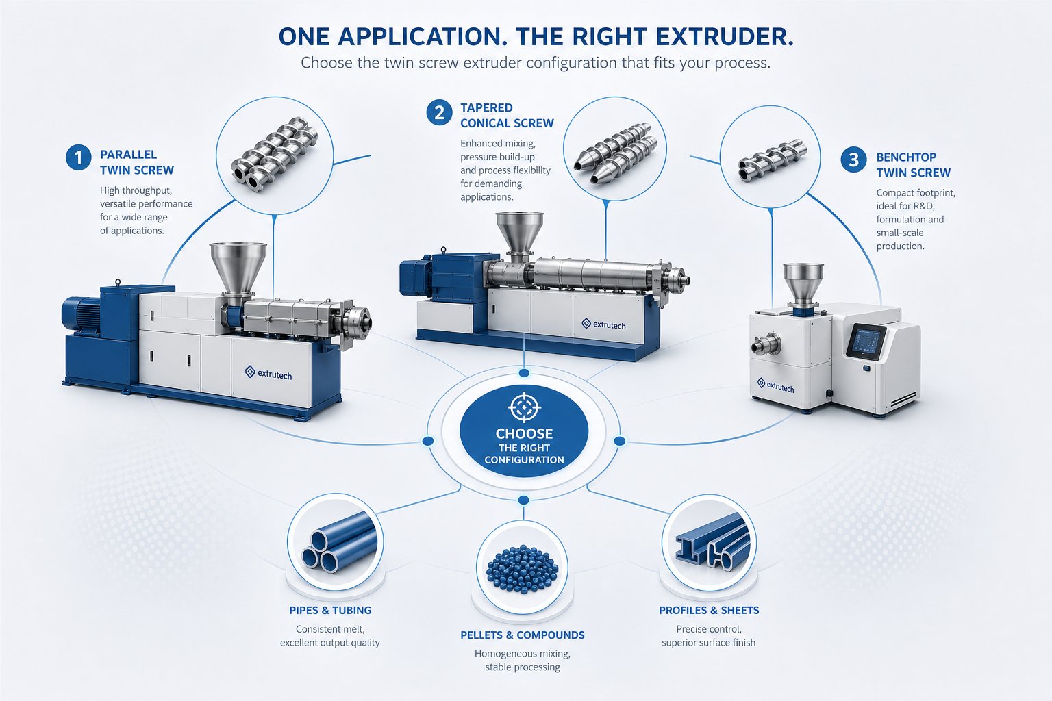
How to Choose the Right Twin Screw Extruder for Your Application
Start with your material and your process goal - not with a machine catalog. Most selection mistakes happen because engineers fall in love with a particular extruder platform before asking the fundamental question: what does my application actually demand? Flip that sequence. Define the material, the transformation it needs, and the throughput you require, then let those answers point you to the right configuration.
Matching Your Application to the Right Twin Screw Extruder Type
The table below reverses the typical equipment-first approach. Find your application scenario in the left column, and the recommended twin screw extruder type follows directly. Whether you are sourcing a twin-screw extruder machine for a new production line or validating an existing setup, this mapping gives you a concrete starting point:
| Application Scenario | Recommended Extruder Type | Why This Configuration Fits |
|---|---|---|
| Polymer compounding and masterbatch production | Co-rotating intermeshing parallel | Modular screw elements allow customized mixing intensity; self-wiping prevents degradation of engineering resins; high throughput at elevated screw speeds |
| PVC pipe and profile extrusion | Counter-rotating conical or counter-rotating parallel | Positive displacement conveying handles heat-sensitive PVC gently; high discharge pressure supports complex profile dies without auxiliary melt pumps |
| Plastic recycling and pelletizing | Co-rotating intermeshing parallel with venting zones | Vacuum venting removes moisture and volatiles from contaminated post-consumer feedstock; self-wiping tolerates variable input quality; a twin screw extruder plastic recycling line with downstream pelletizing delivers consistent output from inconsistent input |
| Screw extruder granulator for filled compounds | Co-rotating intermeshing parallel with side-feeding | Side-feed ports introduce fillers downstream of the melting zone, protecting fiber length and preventing feeder bridging at high loading levels |
| Reactive extrusion (grafting, polymerization, chain extension) | Co-rotating intermeshing parallel with specific kneading and devolatilization configuration | Narrow residence time distribution ensures uniform reaction conversion; modular barrel allows placement of liquid injection and vacuum vent ports at precise locations |
| Food and pharmaceutical continuous processing | Co-rotating intermeshing parallel with specialized barrels and GMP-compliant design | Controlled residence time and temperature uniformity critical for starch gelatinization, hot-melt extrusion of amorphous solid dispersions, and consistent product quality |
| WPC decking and foam board | Counter-rotating conical | Compact footprint with natural compression handles wood-fiber-filled PVC compounds at controlled shear rates |
You'll notice that co-rotating intermeshing parallel machines appear across the widest range of applications. That versatility is precisely why they dominate the global market. Yet for PVC-centric operations and certain niche forming applications, counter-rotating configurations remain the technically superior choice. The key is matching the machine's inherent strengths - mixing intensity, pressure capability, conveying gentleness - to your material's specific sensitivities.
Scale-Up Considerations When Selecting an Extruder Type
Choosing the right configuration is only half the decision. You also need to consider how the process will scale from development to full production. This is where platform choice carries long-term consequences.
Co-rotating intermeshing extruders scale more predictably than any other twin screw type. Their behavior is well characterized through specific mechanical energy (SME) modeling - a metric that relates motor power input to throughput and serves as a reliable bridge between extruder sizes. A case study published by Plastics Technology demonstrated this approach across 26 mm, 40 mm, and 92 mm co-rotating machines: when process adjustments maintained SME within approximately 5% of the laboratory baseline, the production-scale extruder achieved both process stability and target product quality. The predictable relationship between screw diameter, fill ratio, and energy input gives engineers a quantitative framework for scaling - something that reduces trial-and-error and shortens commissioning timelines.
Conical counter-rotating designs face inherent scalability limits. The tapered geometry constrains discharge-end channel volume, and separating forces in the nip grow rapidly with screw diameter. Above certain throughput thresholds, twin screw extruder manufacturers typically recommend transitioning from conical to parallel counter-rotating platforms to achieve higher output without the mechanical compromises that oversized conical screws impose.
For operations beginning at the laboratory stage, selecting a plastic twin screw extruder platform that shares the same OD/ID ratio and screw element geometry as the target production machine simplifies scale-up dramatically. As the reference study highlighted, jumping directly from a small lab extruder to a large production unit risks encountering heat-transfer and feed-behavior changes that invalidate laboratory results. An intermediate pilot-scale step - ideally on equipment from the same twin-screw extruder manufacturer - reduces that risk and provides critical process data for the final production specification.
Partnering with the Right Screw Barrel Supplier
Regardless of which twin screw plastic extruder configuration your facility operates, one reality applies universally: the screw and barrel are the wear components that most directly determine processing performance. Worn screw flights reduce conveying efficiency. Degraded barrel bores increase clearances, compromise self-wiping action on co-rotating machines, and diminish the positive displacement seal on counter-rotating systems. In both cases, product quality deteriorates before the wear becomes visually obvious.
This makes screw and barrel maintenance a strategic decision, not just a procurement task. Technical teams evaluating replacement components need a supplier who understands the differences between extruder types - from the modular segmented elements of a co-rotating compounder to the monolithic tapered screws of a conical PVC line. A supplier who serves only one machine type may not appreciate the metallurgical, geometric, and tolerance requirements of another.
For extrusion manufacturers and recycling plants seeking screw barrel support across all twin screw extruder types - whether for pipe, profile, sheet, pelletizing, or recycling lines - NANHAIYA's plastic extruder machine and screw barrel resources provide a practical starting point. Their support covers the range of configurations discussed throughout this article, connecting technical teams with components matched to their specific extruder design and processing demands. When the screw and barrel are right, the extruder delivers what it was designed to deliver. When they are worn or mismatched, no amount of process optimization can compensate.
Frequently Asked Questions About Types of Twin Screw Extruder
1. What are the main types of twin screw extruders?
Twin screw extruders are classified along three independent axes: rotation direction (co-rotating vs. counter-rotating), intermeshing degree (closely intermeshing, tangential, or non-intermeshing), and screw geometry (parallel vs. conical). The most commercially relevant configurations include co-rotating closely intermeshing parallel extruders for polymer compounding, counter-rotating closely intermeshing conical extruders for PVC profile and pipe production, counter-rotating closely intermeshing parallel extruders for PVC and specialty processing, and tangential counter-rotating extruders for devolatilization. Laboratory-scale and reciprocating variants also serve niche R&D and injection molding compounding roles. Each combination produces distinct mixing behavior, pressure generation, and residence time characteristics that determine its ideal application.
2. What is the difference between co-rotating and counter-rotating twin screw extruders?
Co-rotating twin screw extruders have both screws spinning in the same direction, creating a self-wiping figure-eight material flow path that prevents stagnation and delivers excellent dispersive and distributive mixing at high screw speeds (up to 1,200+ RPM). They dominate polymer compounding, masterbatch, and reactive extrusion. Counter-rotating extruders have screws turning in opposite directions, producing a calendering action that squeezes material through a nip zone. This generates high pressure and positive displacement conveying through sealed C-shaped chambers at lower speeds (often under 150 RPM). Counter-rotating designs excel with heat-sensitive materials like rigid PVC, where gentle handling and predictable output are essential. The choice between them depends primarily on whether your process prioritizes intensive mixing or gentle, pressure-driven conveying.
3. Why are counter-rotating twin screw extruders preferred for PVC processing?
Rigid PVC has a decomposition temperature dangerously close to its processing temperature, making it extremely sensitive to shear-generated heat. Counter-rotating closely intermeshing extruders solve this challenge by conveying PVC powder through sealed C-shaped chambers at low screw speeds with minimal shear input. The calendering effect between screws provides gentle dispersive mixing of stabilizers and fillers without the aggressive shear fields that would overheat the compound. Additionally, the positive displacement mechanism builds high discharge pressure efficiently, which is critical for pushing material through complex profile dies. This combination of low frictional heating, controlled compressive mixing, and strong pressure generation makes counter-rotating designs the standard platform for PVC pipes, window profiles, siding, and WPC decking.
4. What is a conical twin screw extruder and when is it used?
A conical twin screw extruder features screws that taper from a large diameter at the feed end to a smaller diameter at the discharge. This geometry creates a wide feed opening that accepts bulky powders easily while naturally compressing material as it moves forward, building high discharge pressure without needing restrictive screw elements or melt pumps. The wider shaft spacing at the feed end also accommodates a robust gearbox with higher torque capacity. Conical designs are almost exclusively counter-rotating and closely intermeshing, making them ideal for PVC window profiles, rigid PVC pipe, WPC decking, and foam board. Their key limitation is scalability - the taper constrains discharge-end channel volume, so operations needing very high throughputs may need to transition to parallel counter-rotating machines.
5. How do modular screw elements affect twin screw extruder performance?
Modular screw elements are standardized components - conveying segments, kneading blocks, and specialized mixing elements - that slide onto a splined shaft, allowing engineers to customize the screw profile for each formulation without purchasing a new machine. Conveying elements transport material forward or create pressure seals, kneading blocks deliver dispersive or distributive mixing depending on disc width and stagger angle, and gear-type mixing elements blend components with minimal temperature rise. This system is primarily available on co-rotating intermeshing extruders, enabling one machine to handle dozens of different recipes. Counter-rotating and conical designs typically use monolithic one-piece screws that cannot be reconfigured. For any twin screw platform, maintaining screw and barrel components in optimal condition is critical - suppliers like NANHAIYA (nhyscrews.com) provide matched replacement components across all extruder types to maintain processing performance.
Written by
Nanhaiya Technical Team
Zhoushan Nanhaiya Plastic Machinery Co., Ltd.
The Nanhaiya technical team supports screw and barrel manufacturing projects through application review, technical communication, custom manufacturing coordination, and production and quality control.
Discuss Your Application
Related Articles
More insights on screw barrel technology and plastics processing.

Extruder Machine Decoded: From Raw Pellet To Finished Product
Oct 6, 2026
Learn how an extruder machine works, compare single-screw vs. twin-screw types, and get expert guidance on specs, troubleshooting, and selection.
Read Article
PE Pipe Making Machine Decoded: From Raw Resin to Flawless Pipe
Oct 4, 2026
Learn how a PE pipe making machine works, from resin to finished pipe. Covers components, material grades, automation, troubleshooting, and buyer selection tips.
Read Article
PVC Profile Making Machine Decoded: From Raw Resin To Profit
Oct 3, 2026
Learn how a PVC profile making machine works — extrusion process steps, key technical parameters, die design, calibration methods, maintenance, and total cost of ownership.
Read ArticleLooking for something else?
Search by material, symptom or product and jump straight to the relevant page.
These are navigation suggestions based on keyword matching — not a quotation, not a delivery commitment, and not a substitute for engineering review. Final specification is confirmed by our engineers against your drawings and processed material.
Need help with screw barrel selection?
Share your machine model, processed material and application. Our team can help with pricing and technical support.