

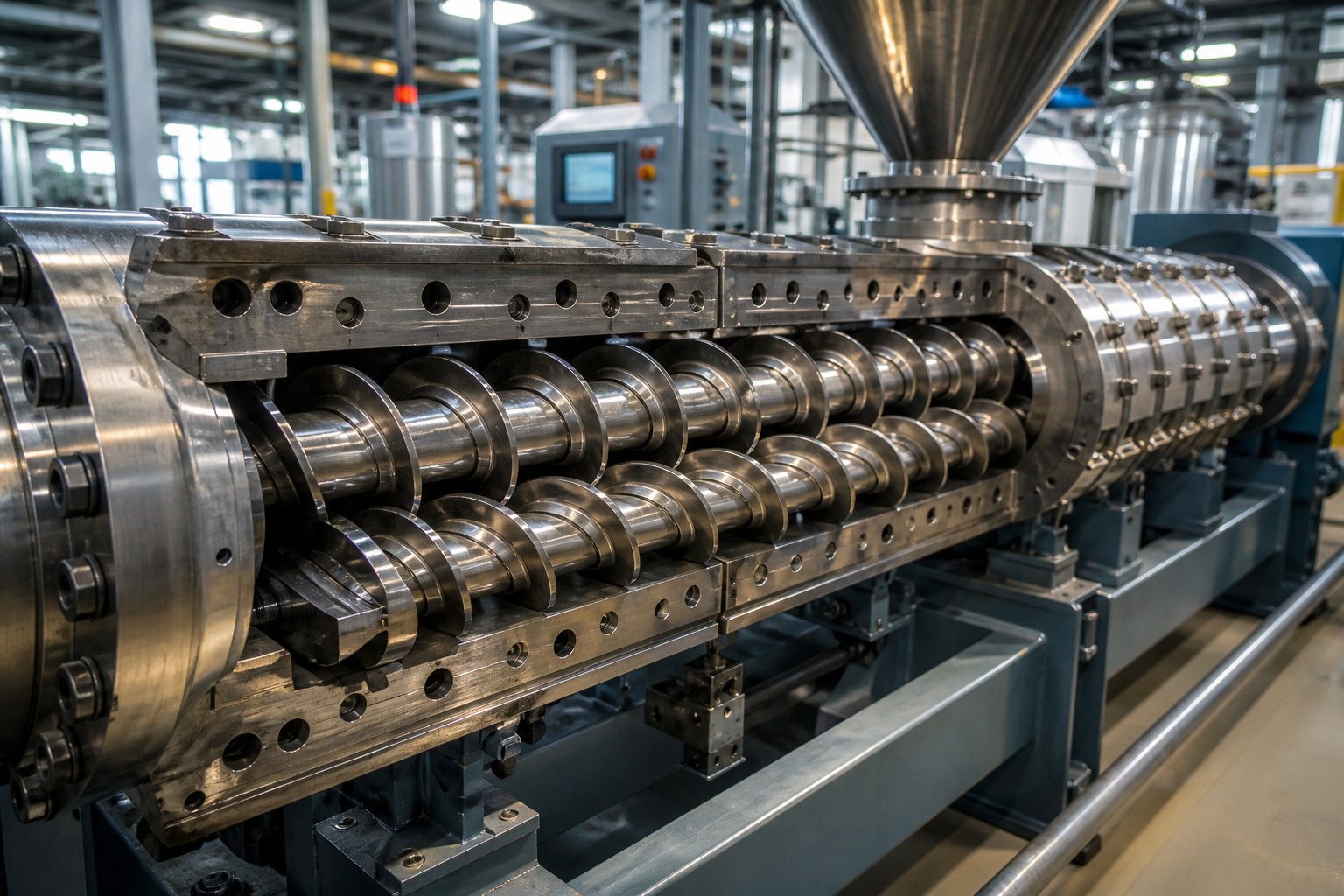
What Are Twin-Screw Extruders and Why They Matter
Imagine two helical screws spinning side by side inside a heated barrel, grabbing raw material at one end and pushing out a perfectly blended, molten product at the other. That, in the simplest terms, is the core idea behind twin-screw extruders. They show up in plastics compounding lines, masterbatch production facilities, recycling plants, and even pharmaceutical labs—and for good reason. Their ability to simultaneously convey, melt, mix, and shape materials in a single continuous process makes them one of the most versatile workhorses in modern manufacturing.
Whether you're a newcomer trying to grasp the fundamentals, an engineer evaluating equipment options, or an operator looking to squeeze more performance out of an existing line, this article breaks down every critical detail—from internal flow mechanics and screw configuration design to troubleshooting strategies and barrel maintenance.
What Exactly Is a Twin-Screw Extruder
A twin screw extruder is a machine that uses two intermeshing, co-rotating or counter-rotating screws housed within a closely fitted barrel to transport, melt, mix, and pressurize materials into a continuous, homogeneous output. It is the preferred platform for any process that demands thorough blending of multiple ingredients under tightly controlled thermal and mechanical conditions.
You'll often see the term "double screw extruder" used interchangeably with "twin screw extruder" across industry literature, trade catalogs, and international supplier listings. Both refer to the same class of equipment. Understanding this synonym is helpful when researching extruders meaning and specifications from global manufacturers, since terminology can vary by region. The word "extruder" itself traces back to the Latin extrudere—to push out—which is exactly what these machines do: they force processed material through a die to create pellets, profiles, sheets, or films.
Why Twin-Screw Technology Became the Industry Standard
Single-screw machines handle straightforward melting and forming tasks well enough. But the moment a process calls for compounding additives into a polymer, dispersing pigments at high loading levels, devolatilizing contaminants from recycled feedstock, or running reactive extrusion in pharmaceuticals, twin screw extruders pull ahead decisively. Here's why:
- Superior mixing: The intermeshing screw geometry generates both distributive and dispersive mixing forces, ensuring uniform blending of fillers, colorants, and stabilizers throughout the melt.
- Self-wiping action: As each screw flight sweeps the surface of its counterpart, material is continuously scraped away from barrel walls and screw channels. This eliminates stagnant zones where heat-sensitive polymers could degrade—a persistent challenge in single-screw systems.
- Modular flexibility: Individual screw elements and barrel segments can be rearranged on a splined shaft to tailor the machine for vastly different applications, from gentle blending of temperature-sensitive food ingredients to high-shear dispersion of nano-fillers.
- Precise process control: Independent adjustment of screw speed, feed rate, and multi-zone barrel temperatures gives engineers fine-grained command over residence time, shear input, and melt quality.
The defining advantage of twin-screw extruders over single-screw alternatives is their ability to deliver intensive, uniform mixing with self-wiping geometry and modular screw configurations—making them adaptable to virtually any compounding, recycling, or reactive processing challenge.
These core strengths explain why twin-screw extruders have become the standard across plastics, food, and pharma sectors. Yet the real engineering depth lies beneath this surface-level overview—in the flow mechanics that make all of this mixing possible.
How Twin-Screw Extrusion Actually Works
Knowing what a twin-screw extruder does is one thing. Understanding how it does it is where real process mastery begins. Inside the barrel, material doesn't simply ride forward on a conveyor belt. Instead, three distinct flow mechanisms compete and interact with every rotation of the screws—and that interplay is precisely what makes twin screw extrusion so effective at producing homogeneous compounds.
Drag Flow, Pressure Flow, and Leakage Flow Explained
Think of a rotating screw as a spiral staircase that's been laid on its side. As the screw turns, its helical flights push material forward along the barrel—much like your hand dragging honey across a plate. This forward-pushing action is called drag flow, and it's the primary mechanism responsible for moving material from the feed opening toward the die. The faster the screw spins, the stronger the drag flow becomes.
At the discharge end, however, the die creates resistance. Material can't exit freely, so pressure builds up and forces some of the melt backward against the direction of travel. This opposition is known as pressure flow. Imagine squeezing toothpaste toward the cap while someone partially blocks the opening—some paste pushes back toward your hand. In screw extrusion, the pressure gradient between the die and the feed end drives this reverse current, and managing the balance between drag flow and pressure flow is critical for maintaining stable output rates.
The third mechanism is leakage flow—small amounts of material that escape through the narrow clearances between screw flight tips and the barrel wall, or through the gaps in the intermeshing region between the two screws. While leakage flow is sometimes viewed as parasitic because it reduces volumetric pumping efficiency, it actually contributes to mixing quality by forcing material through tight gaps where it undergoes intense shear.
Here's what makes the twin screw extrusion process fundamentally different from single-screw systems: the intermeshing, self-wiping geometry of two screws creates a figure-eight flow path that constantly transfers material from one screw channel to the other. This cross-channel movement eliminates dead zones—pockets where material could stagnate, overheat, and degrade. In a single-screw machine, material can cling to the barrel wall or settle into low-flow regions. In a twin-screw system, every particle is swept, folded, and reoriented repeatedly, resulting in far superior distributive and dispersive mixing.
The Twin-Screw Extrusion Process From Feed to Die
Material doesn't go from raw pellets to finished product in one vague step. A twin-screw extruder is organized into distinct functional zones, each performing a specific task in sequence. Understanding this progression helps engineers and operators pinpoint exactly where in the barrel a problem originates—and where adjustments will have the greatest impact.
- Feeding zone: Raw materials—pellets, powders, or liquids—enter the barrel through a feed throat, typically via a gravimetric or volumetric feeder. The screws operate in a starve-fed condition here, meaning the barrel is only partially filled, which allows precise control over material intake.
- Conveying zone: Conveying screw elements with deep flights transport the loosely packed material forward. Air trapped among particles escapes rearward through the partially filled channel. The material begins absorbing heat from the barrel walls but remains largely solid.
- Melting and plasticizing zone: Kneading blocks and narrower-pitch elements apply mechanical shear, converting solid particles into a continuous melt. Friction between the material, the screw surfaces, and the barrel wall generates additional heat. This is where the majority of phase transition occurs.
- Mixing and kneading zone: Additional kneading elements intensify distributive and dispersive mixing, breaking down agglomerates and uniformly distributing additives, fillers, or pigments throughout the melt. Stagger angles and disc widths in these blocks are selected to match the required mixing intensity.
- Venting and devolatilization zone: An open-top barrel section exposes the melt to atmospheric pressure or vacuum. Trapped moisture, volatiles, and reaction byproducts escape as gas. A melt seal created by reverse screw elements upstream prevents material from flooding the vent port.
- Pumping and die discharge zone: Tight-pitch conveying elements build the pressure needed to push the homogeneous melt through the die. The die shapes the output into strands, films, profiles, or sheets, which are then cooled and pelletized downstream.
The primary compounding operations of a parallel twin-screw compounder—feeding, melting, conveying, mixing, venting, and extrusion of the homogenized product—follow this sequence in virtually every application, as outlined by Thermo Fisher Scientific's process parameters overview.
One metric ties all these zones together and deserves far more attention than it typically receives: specific energy input (SEI), sometimes referred to as specific mechanical energy (SME). Expressed in kilowatt-hours per kilogram (kWh/kg), SEI quantifies how much energy the extruder's drive motor transfers through the screws and into the material being processed. It is calculated from motor power, screw speed, torque, and throughput rate.
Why does this matter? Because SEI acts as a diagnostic fingerprint for the entire twin screw extrusion process. Too-low SEI typically signals insufficient melting or mixing—material passes through the barrel without receiving enough mechanical work, resulting in poor dispersion or unmolten particles. Too-high SEI, on the other hand, indicates excessive shear, which can overheat the melt and trigger thermal degradation. A Dow case study on scaleup across 26-mm, 40-mm, and 92-mm extruders demonstrated this vividly: when the optimized SME of approximately 0.083 kWh/kg achieved on the laboratory-scale machine dropped to 0.026 kWh/kg on the 92-mm production extruder, solid pellets discharged unmelted, and the process became unsustainable. Restoring the SME to 0.086 kWh/kg through screw redesign and feed adjustments resolved the issue entirely.
For process engineers, monitoring SEI provides a single number that captures the combined effects of screw speed, feed rate, and barrel temperature profile. It's especially valuable during scaleup, where matching the SEI from a laboratory extruder to a production machine helps replicate product quality at higher throughput—a challenge that can otherwise derail commercialization timelines.
With the flow physics and process zones mapped out, the next logical question becomes: how does the direction of screw rotation change everything? Co-rotating and counter-rotating configurations produce strikingly different flow fields, pressure profiles, and mixing behaviors—differences that determine which design suits a given application.
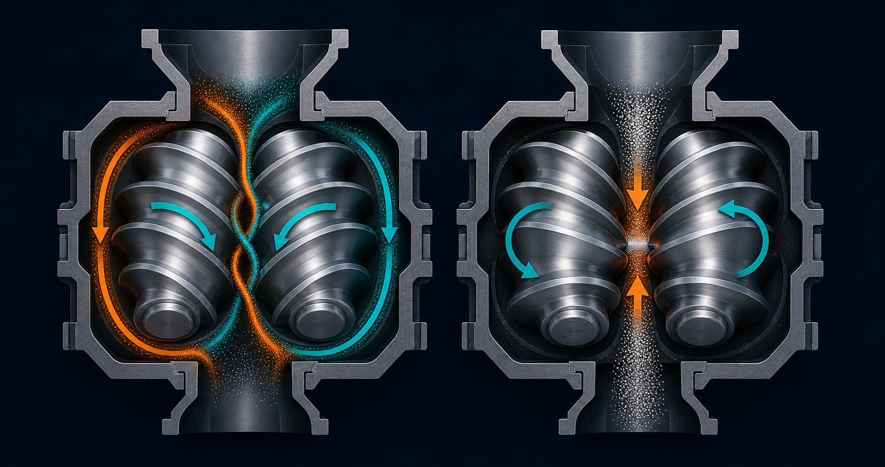
Co-Rotating vs Counter-Rotating Twin-Screw Configurations
Rotation direction might sound like a minor detail. After all, the twin screws spin, material moves forward, and product comes out the die—right? In practice, whether those two screws turn the same way or in opposite directions reshapes the entire flow field inside the barrel. It changes how material is handed from one screw to the other, how much shear the melt experiences, how much pressure builds before the die, and ultimately which applications the machine can handle well. Choosing between a co rotating twin screw extruder and a counter-rotating one is less about preference and more about physics.
Mechanical Differences Between Co-Rotating and Counter-Rotating Designs
In a co rotating twin screw extruder, both screws spin in the same direction—either both clockwise or both counterclockwise. A fully intermeshing geometry is the standard here, meaning the flight of one screw reaches deep into the channel of the other with minimal clearance. Picture two gears meshing together while turning the same way: material caught between them gets forcibly transferred from one screw channel to the next at the intermeshing zone. This transfer creates a distinctive figure-eight flow path as the melt zigzags between the two screws along the barrel length.
That figure-eight pattern is the engine behind the co-rotating design's famous mixing intensity. Material doesn't just travel forward—it gets folded, split, and reoriented with every pass through the intermeshing region. The self-wiping action is equally important: because the flight tip of one screw constantly sweeps the root of its partner, virtually no material can stagnate. Dead zones disappear, and the residence time distribution stays narrow—a critical factor when processing thermally sensitive polymers or running reactive extrusion where even a few extra seconds of heat exposure can degrade the product.
Counter-rotating designs flip the script. Here, the twin screws rotate in opposite directions—one clockwise, the other counterclockwise. At the intermeshing zone, the screw surfaces move toward each other rather than alongside each other. Material gets drawn into the narrowing gap between the screws and compressed as it passes through. Imagine two rollers in a printing press squeezing paper between them. That analogy captures the calendering effect that defines counter-rotating extrusion: material undergoes compressive and elongational deformation rather than the high-shear folding action seen in co-rotating machines.
This calendering mechanism produces gentler processing conditions. Shear stress between the screws is lower, shear-induced heat generation drops, and material temperature stays closer to the barrel setpoint. As Technovel's extrusion specialists note, counter-rotating machines allow extrusion at low temperatures while suppressing any rise in material temperature—a decisive advantage for compounds like rigid PVC that sit dangerously close to their thermal decomposition temperature during processing.
There's a trade-off, of course. The lower shear environment means counter-rotating extruders cannot match the intensive distributive and dispersive mixing that co-rotating systems deliver. They also operate at lower screw speeds and often run fully filled rather than starve-fed, which limits the flexibility to adjust fill level and residence time independently.
When to Choose Each Configuration
Selecting between co-rotating and counter-rotating configurations comes down to matching the machine's flow mechanics to your material's needs and your process goals. The comparison table below lays out the key differences across the criteria that matter most in practice:
| Criteria | Co-Rotating Twin Screw Extruder | Counter-Rotating Twin Screw Extruder |
|---|---|---|
| Mixing Intensity | High—strong shear fields develop between screws and between screw and barrel; kneading blocks add elongational flow | Moderate—relies on compressive and elongational deformation via calendering effect; lower shear stress |
| Pressure Generation | Moderate—effective for compounding but may require gear pumps for high-pressure die applications | High—opposing screw rotation and conical taper naturally compress material, building strong die pressure |
| Self-Wiping Capability | Excellent—fully intermeshing geometry continuously scrapes all surfaces, eliminating dead zones | Good in intermeshing designs; poor in non-intermeshing configurations where screws operate independently |
| Shear Rate | High—screw speeds commonly reach 400-900 RPM; some high-speed models exceed 1,000 RPM | Low to moderate—typical operating speeds range from 30-150 RPM, minimizing shear heating |
| Throughput Range | Wide—starve-fed operation allows flexible adjustment; highest throughput rates among twin-screw types | Narrower—operates at high fill levels and lower speeds; throughput linked closely to screw rotation rate |
| Primary Applications | Compounding, masterbatch, polymer blends, reactive extrusion, nanocomposites, recycling | PVC pipe and profile extrusion, wood-plastic composites, thermally sensitive polymer processing |
| Typical Screw Geometry | Parallel (constant diameter along full length)—modular barrel and screw elements are easily interchangeable | Conical (tapered from feed to discharge) is most common; some parallel counter-rotating designs exist for devolatilization |
A few patterns jump out from this comparison. If your process demands intensive blending of multiple additives, high-shear dispersion of fillers or pigments, or the flexibility to reconfigure the screw layout between product runs, a co-rotating machine is the natural fit. Parallel twin screw extruders dominate this space because their constant-diameter barrel design supports true modularity—you can swap individual barrel segments and screw elements in and out to adapt the same machine to compounding, devolatilization, or reactive extrusion tasks.
When the application involves thermally fragile materials like rigid PVC, or when the process requires high die pressure for pipe and profile forming, a counter-rotating design earns its keep. The conical twin screw extruder is the workhorse here. Its tapered screws—wider at the feed end, narrower at the discharge—create a natural compression ratio that builds pressure progressively while keeping shear gentle. That geometry also allows for larger bearings at the wide end of the screws, which increases the torque capacity of the gearbox and improves mechanical reliability under high-load conditions.
One distinction within counter-rotating designs deserves its own attention: intermeshing versus non-intermeshing configurations. In intermeshing counter-rotating machines, the screw flights of one screw fit closely into the channels of the other, creating the calendering effect described earlier. This is the standard setup for PVC processing. Non-intermeshing counter-rotating extruders, by contrast, position the twin screws far enough apart that their flights never make contact. Each screw essentially processes its own channel of material independently. The result is the lowest shear environment of any twin-screw configuration—ideal for high-level devolatilization (removing 30% or more volatiles), processing shear-sensitive specialty polymers, and pharmaceutical hot-melt extrusion where precise, gentle thermal control is paramount.
In short, the choice between co rotating and counter rotating twin screw extruder designs isn't a matter of one being "better" than the other. It's a matter of matching flow physics to material behavior. Get that match right, and the extruder works with you. Get it wrong, and you'll fight degradation, poor dispersion, or unstable output from day one.
Rotation direction and screw geometry set the boundaries of what's possible—but the real performance tuning happens at the component level. The barrel segments, screw elements, and metallurgical choices that go inside these machines determine whether the theoretical advantages actually show up on the production floor.
Essential Components and Modular Barrel-Screw Systems
Strip away the motor, gearbox, and control panel, and a twin-screw extruder is fundamentally a barrel wrapped around two shafts loaded with interchangeable elements. Sounds simple? The engineering depth hiding inside that barrel-and-screw assembly is what separates a capable extruder system from a mediocre one. Every barrel segment, every screw element, and every metallurgical decision plays a specific functional role—and understanding those roles is essential for anyone specifying, operating, or maintaining this equipment.
Modular Barrel Segments and Their Functions
Unlike a single-screw machine where the barrel is often one continuous cylinder, a twin-screw extruder barrel is built from individual segments bolted together end to end. Each segment can be configured differently based on its position in the process. You'll typically encounter three main types:
- Closed barrel segments: These are solid-walled sections used in conveying and melting zones. Their job is containment—keeping material under pressure and in full contact with the heated barrel wall to facilitate heat transfer and maintain melt stability.
- Open-top barrel segments: These feature ports cut into the top of the barrel for material feeding or gas venting. Feed barrels accept the main hopper, side feeders for downstream addition of fillers and fibers, or liquid injection nozzles. Vent barrels expose the melt to atmosphere or vacuum so that moisture, trapped air, and volatile byproducts can escape.
- Jacketed barrel segments: Equipped with internal channels for circulating heating oil or cooling water, these segments provide precise thermal control. Some zones need aggressive heating to initiate melting, while others need cooling to prevent shear-induced overheating in kneading-intensive regions.
This modularity means you can reconfigure the same machine for completely different processes simply by rearranging barrel sections—moving a vent port further downstream, adding a side-feed barrel for glass fiber incorporation, or swapping a standard segment for one with enhanced cooling capacity.
Barrel metallurgy is where longevity gets engineered in—or engineered out. The twin screw and barrel interface is a high-wear zone. Every kilogram of material that passes through grinds against the barrel's inner bore, and abrasive fillers like glass fiber, calcium carbonate, or titanium dioxide accelerate that erosion dramatically. The industry relies on a progression of metallurgical solutions matched to processing severity:
- Nitrided steel (e.g., 38CrMoAlA): The baseline for general-purpose polymer compounding. A nitrogen-diffusion surface treatment creates a hard case layer that resists moderate abrasive wear at an accessible cost point.
- Bimetallic liners: A wear-resistant alloy—typically iron-based with high boron and chromium content—is centrifugally cast inside a structural steel shell. This construction provides significantly higher abrasion resistance than nitriding alone and allows the liner to be replaced when worn without discarding the entire barrel body. As ENTEK's metallurgy engineers have documented, lined barrels can be refurbished by removing the worn liner and inserting a new one, reusing the body with its machined cooling passages, thermocouple wells, and bolt holes—substantially reducing long-term cost of ownership compared to one-piece barrels.
- Tungsten carbide or ceramic coatings: Reserved for the most abrasive applications—high glass-fiber loadings, mineral-filled engineering plastics, or recycled feedstock contaminated with metal particles. These coatings deliver extreme hardness values but come at premium cost and require specialized application processes.
Choosing the right metallurgy isn't just an upfront purchasing decision—it's a wear-life calculation. The wrong liner material in a highly filled compound can erode within weeks, widening the clearance between screw flights and barrel wall. That increased clearance degrades conveying efficiency, reduces mixing quality, and eventually forces unplanned downtime for replacement. When barrel replacement does become necessary, sourcing high-quality components from specialized manufacturers is critical. NANHAIYA, for example, produces custom parallel twin screw barrels engineered for compounding, masterbatch, recycling, and pelletizing applications—offering barrels optimized for stable conveying and high-wear resistance that match the demands of specific processing conditions.
Screw Elements That Define Process Performance
If the barrel provides the container, the extruder screw elements provide the action. Individual elements slide onto a splined shaft and are locked in sequence, creating a complete screw profile that dictates exactly how material is transported, melted, mixed, and pressurized at every point along the barrel length. This is the heart of modularity in twin-screw extrusion—and the reason why process engineers can tune the same machine for hundreds of different formulations without changing the base hardware.
The three primary element categories each serve a distinct purpose in the extruder screw and barrel system:
- Conveying elements: Helical flights that transport material forward. Pitch is the key variable—large-pitch elements move material quickly with low shear and low pressure buildup, ideal for feed zones where you want rapid intake without overloading downstream sections. Short-pitch elements slow material down, increase the fill level, and build pressure, making them essential in the pumping zone near the die. Improper conveying geometry can overload downstream kneading sections, creating excessive melt temperature spikes and torque surges.
- Kneading blocks: Stacks of elliptical discs offset at specific angular intervals. These are the primary mixing workhorses. The stagger angle between discs governs intensity: a 30-degree offset provides moderate, forward-conveying mixing; a 60-degree offset delivers aggressive dispersive shear; and a 90-degree (neutral) offset maximizes residence time and mixing energy with virtually no forward conveying. Wider discs favor dispersive mixing—physically breaking down agglomerates—while narrower discs promote distributive mixing, spreading the dispersed phase uniformly without reducing particle size. As NC State Extension's extrusion research explains, forward kneading elements are less aggressive, neutral elements only impart energy and increase residence time, and reverse kneading blocks push material backward, creating maximum restriction and maximum shear.
- Reverse elements: These are conveying elements with opposite-hand flight geometry, intentionally pushing material backward against the main flow direction. They create localized melt seals—fully filled, high-pressure zones that serve two critical functions: preventing material from flooding upstream into vent ports, and increasing residence time in mixing zones where additional energy input is needed. Without properly positioned reverse elements, vacuum venting becomes impossible because melt would simply flow up and out of the vent opening.
- Toothed mixing elements: Gear-like elements that split and recombine the melt stream repeatedly. They excel at distributive mixing—achieving uniform spatial distribution of additives—while generating minimal temperature rise compared to aggressive kneading blocks. These elements fill a niche when you need thorough blending without the thermal penalty of high shear.
Engineers sequence these elements strategically to build application-specific screw profiles. A compounding line for color masterbatch might stack aggressive kneading blocks in the mixing zone to break down pigment agglomerates, while a recycling line processing degradation-sensitive HDPE might rely on gentler toothed mixing elements paired with extended conveying sections. The extruder screw configuration—not the machine frame, not the motor, not the brand name—is what ultimately defines product quality.
Knowing which elements exist and what they do is the foundation. The deeper engineering challenge lies in figuring out where each element belongs on the shaft—and how changing its position by even one slot can alter melt temperature, torque load, and dispersion quality in ways that ripple through the entire process.
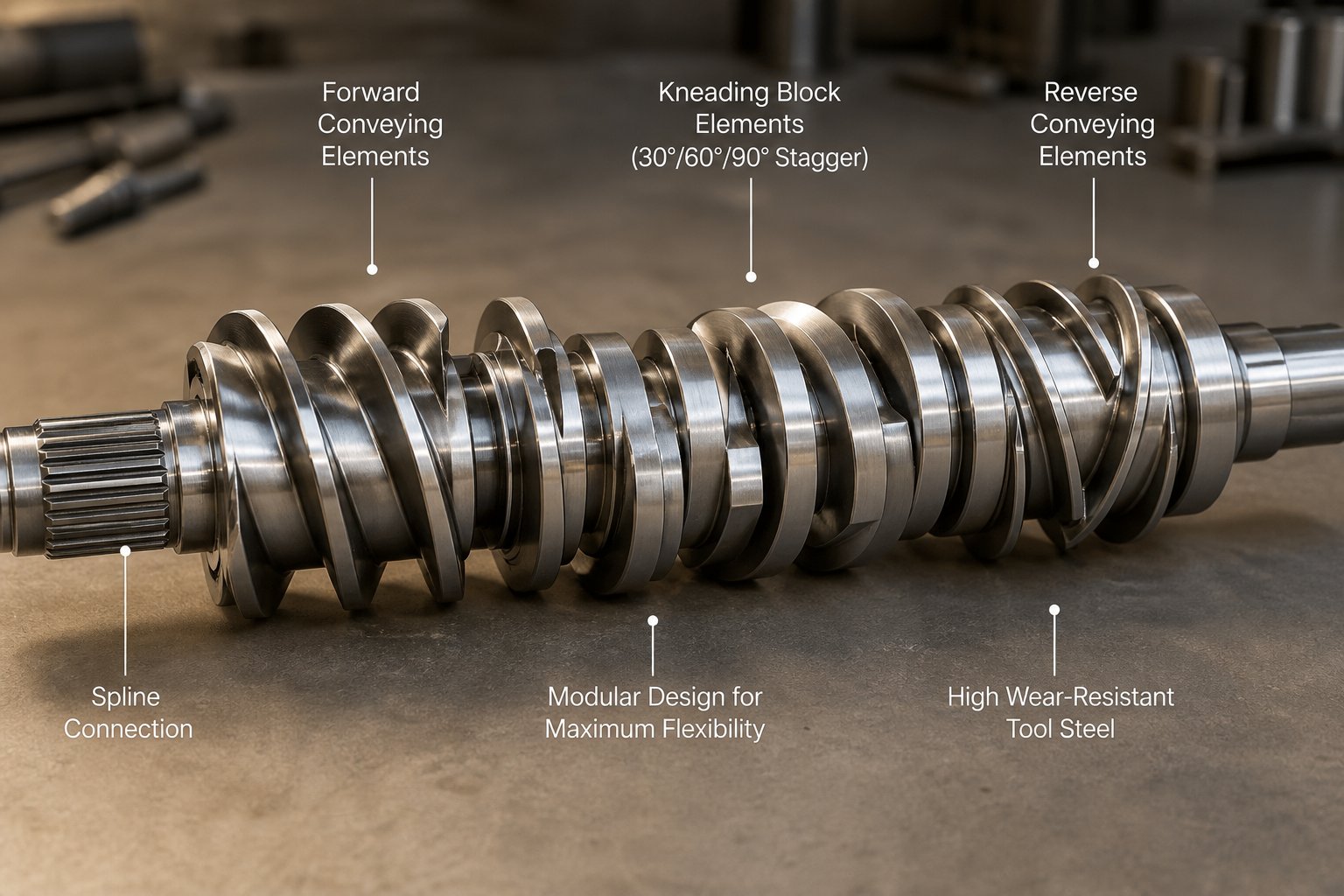
Screw Configuration Design Principles for Extruder Twin Screw Systems
Every element on a splined shaft has a job. But placing those elements in the right sequence—and tuning their geometry to match the material, throughput, and quality targets—is what separates a functional plastic extruder screw layout from an optimized one. The ability to customize screw geometry element by element is the defining engineering advantage of twin-screw extruders. No other mixing platform offers this level of reconfigurability. Yet it's also the area where most technical resources go silent, leaving engineers to rely on trial and error or supplier rules of thumb that may not translate across applications.
Screw configuration design boils down to two interconnected challenges: understanding how individual elements behave, and knowing how to arrange them into a coherent profile that controls melting, mixing, venting, and pressure generation across the full barrel length.
How Kneading Block Geometry Controls Mixing
Kneading blocks are the primary mixing workhorses in any screw extruders configuration. But not all kneading blocks behave the same way. Three geometric variables determine how aggressively a kneading block works the material—and getting those variables right is the difference between excellent dispersion and a degraded, overheated product.
Disc width is the first lever. Imagine a kneading block as a stack of elliptical paddles. A narrow-disc block slices through the melt, splitting and redistributing it across the screw channel—this promotes distributive mixing, spreading additives uniformly without breaking them down further. A wide-disc block, by contrast, acts more like a plow. It forces a greater proportion of material over the tip of each disc and through the tight gap between the disc and the barrel wall. That high-shear zone delivers dispersive mixing—physically rupturing agglomerates, breaking down pigment clusters, or delaminating layered fillers. As Plastics Technology's kneading block analysis explains, increasing disc width causes more polymer to flow over the disc tip, subjecting it to the highest shear forces in the extruder and resulting in higher melt temperatures.
Stagger angle—the angular offset between consecutive discs—is the second variable. Think of it as a dial that controls how hard the block pushes material forward versus how much energy it dumps into mixing:
- 30-degree offset: Gentle, forward-conveying action. The block moves material downstream efficiently with minimal energy input. Best suited for transitioning from conveying elements into the melting zone without creating excessive backpressure.
- 60-degree offset: Moderate mixing intensity with reduced forward-conveying capability. These blocks begin to trap and work the melt more aggressively, generating meaningful shear without fully stalling the flow.
- 90-degree offset (neutral): Maximum mixing intensity. The block imparts energy to the polymer but provides zero net forward conveyance—material moves only because upstream elements push it through. Residence time spikes in this region, and melt temperature rises sharply. NC State Extension's screw design research confirms that neutral kneading elements do not convey material at all, making them the most aggressive option for energy input.
Reverse-staggered kneading blocks take this further. By offsetting discs in the opposite rotational direction, these elements actively push material backward. A reverse 30-degree block is more severe than a reverse 60-degree block because the tighter stagger angle pumps more material upstream, creating a longer dwell time under intense shear conditions.
Number of discs per block is the third variable. Most kneading blocks contain four to five discs, though configurations range from three to seven. For a given block length, increasing the disc count produces narrower individual discs—shifting the balance toward distributive mixing. Reducing the count yields wider discs and more dispersive action. Engineers often specify disc count in tandem with block length to fine-tune the energy-input profile for a specific polymer or filler system.
These three parameters—disc width, stagger angle, and disc count—don't operate in isolation. A wide-disc, 90-degree block delivers the most aggressive shear environment possible, generating the highest melt temperatures and longest local residence times. A narrow-disc, 30-degree block is the gentlest option, providing light distributive mixing with efficient forward conveyance. Every combination in between offers a different trade-off, and selecting the right one depends on the material's melt viscosity, thermal sensitivity, and the specific mixing task at hand.
Building a Screw Profile for Specific Applications
Knowing how individual elements behave is necessary but not sufficient. The real skill lies in assembling them into a complete plastic extrusion screw profile that achieves the desired process outcome across all barrel zones simultaneously. While every application demands its own tailored solution, several design principles hold true across virtually all twin-screw compounding operations:
- Start with high-pitch conveying elements at the feed throat. Large-pitch flights maximize free volume and intake capacity, preventing bridging or feed limitations—especially important when processing low-bulk-density powders or fluffy recycled flake.
- Transition to shorter-pitch conveying elements before the melting zone. Gradually reducing pitch increases fill level and prepares the material for the higher-energy kneading section ahead. This prevents sudden pressure spikes and torque surges.
- Position kneading blocks at the melting and mixing zones. Begin with a forward-conveying kneading block (30-degree) to ease the transition from conveying elements, then increase intensity with 60-degree and 90-degree blocks. Leistritz research demonstrated that an extended melting zone using narrow-disc, less-intensive elements produced both higher throughput rates and lower melt temperatures compared to an aggressive melting zone compressed into fewer barrel sections.
- Place reverse elements immediately upstream of each vent port. A left-hand conveying element or reverse kneading block creates a fully filled melt seal that prevents molten material from flooding upward through the vent opening. Without this seal, vacuum devolatilization becomes impossible.
- Use gentle mixing elements after vent zones. Aggressive kneading blocks downstream of the vent can re-entrain the volatiles you just removed. Toothed mixing elements or narrow-disc forward kneading blocks provide additional blending without generating excessive shear or temperature.
- Finish with tight-pitch conveying elements at the discharge. These elements build stable pressure for the die, ensuring consistent output rate and uniform strand or pellet quality. The pressure generated here also contributes to melt temperature rise—a factor that must be accounted for in the overall thermal budget.
In practice, screw configuration is an iterative process. Engineers rarely get the perfect profile on the first attempt. The typical development cycle works like this: start with a baseline configuration based on known design rules, run the extruder at target conditions, and then evaluate three key feedback signals—torque readings (indicating mechanical load), melt temperature (indicating shear-induced heating), and product quality (dispersion level, appearance, mechanical properties). If torque runs too high, it may signal an overly aggressive kneading section or excessive fill level. If melt temperature exceeds acceptable limits, the kneading blocks may need to be spread over a longer barrel length or swapped for narrower-disc elements. If dispersion is insufficient, additional kneading intensity or a reverse element to increase residence time may be needed.
Screw design is an art—engineers will design screws differently to achieve the same function, and both approaches can be acceptable if the product quality meets requirements.
That observation, shared by veteran compounding engineer Kenneth Russell in Plastics Technology, captures an important reality: there is no single "correct" screw profile for any given material. The modular nature of the plastic extruder screw system means that multiple configurations can produce acceptable results, and optimization is a continuous process driven by data, experience, and material-specific behavior.
With the screw configuration toolkit in hand, a natural next question emerges: how does this element-level engineering translate into choosing between a twin-screw and a single-screw machine in the first place—and what decision criteria should guide that selection?
Twin-Screw vs Single-Screw Extruder Selection Guide
Configuring a screw profile element by element is a powerful capability—but it only matters if you're running the right type of machine in the first place. The single most common equipment decision in polymer processing is whether a given application calls for a single-screw or a twin-screw extruder machine. Get that decision wrong, and no amount of kneading block optimization will compensate. Get it right, and you've built the foundation for efficient, stable production from day one.
The trouble is, this comparison often gets reduced to vague statements like "twin-screw is better for mixing." That's true, but it's not actionable. What you actually need is a structured side-by-side view of where each architecture excels—and a clear decision path that matches machine type to your material, process, and budget.
Core Mechanical and Process Differences
A single screw extruder relies on friction between the polymer and the barrel wall to generate drag flow—the sole mechanism driving material forward. It excels at steady-state melting and pressure generation for pre-compounded pellets. A twin-screw extruder, by contrast, uses intermeshing screws that provide positive displacement and intensive internal mixing. That mechanical distinction cascades into performance differences across every process parameter that matters:
| Decision Criteria | Single-Screw Extruder | Twin-Screw Extruder |
|---|---|---|
| Mixing Capability | Low to moderate—limited to what barrel shear and optional static mixers can achieve | High—modular kneading blocks deliver both distributive and dispersive mixing across multiple zones |
| Feed Flexibility | Flood-fed; requires consistent pellet or granule feedstock for stable output | Starve-fed via gravimetric feeders; handles powders, flakes, dry blends, and inconsistent recycled streams |
| Residence Time Distribution | Broad—material near the barrel wall moves slower than material in the screw channel center, causing uneven thermal history | Narrow—self-wiping and cross-channel flow ensure all particles experience similar processing time and shear exposure |
| Self-Wiping | None—material can stagnate in low-flow regions, risking degradation of heat-sensitive polymers | Continuous—intermeshing flights scrape all barrel and screw surfaces, eliminating dead zones |
| Modularity | Limited—screw is typically a one-piece design; process adjustments require a new screw | High—individual conveying, kneading, and reverse elements can be rearranged on a splined shaft for different formulations |
| Throughput Range | High-volume continuous output; well-suited for dedicated production lines | Flexible range from laboratory scale (a few kg/h) to industrial scale (tens of thousands of kg/h) |
| Capital Cost | Lower—simpler gearbox, single screw, less complex barrel design | Higher—precision-machined intermeshing screws, heavy-duty gearbox, modular barrel system |
| Typical Applications | Pipe, tube, profile, sheet, and film extrusion from pre-compounded pellets | Compounding, masterbatch, reactive extrusion, devolatilization, recycling, pharmaceutical hot-melt extrusion |
The pattern is straightforward. A single screw extruder is the practical, cost-effective architecture when the material arrives as a uniform, pre-compounded pellet and the line simply needs to melt, pressurize, and form it. A double screw extruder machine earns its place when the process itself must perform the compounding—blending multiple raw ingredients, dispersing fillers, removing volatiles, or reacting components within the barrel.
A Decision Framework for Extruder Selection
Rather than debating features in the abstract, imagine walking through a checklist every time a new project lands on your desk:
- What form is the feedstock? Consistent pellets point toward single-screw. Powders, dry blends, fluffy regrind, or multi-component recipes push toward twin-screw.
- Where does mixing happen? If the resin supplier already compounded the material, the extruder only needs to remelt it—single-screw territory. If the extruder must combine base resin with fillers, pigments, stabilizers, or reactive additives, only a twin-screw extruder delivers the mixing intensity required.
- Does the process need devolatilization? Removing moisture, monomers, or solvents from the melt requires open vent barrels and upstream melt seals—features native to twin-screw systems but difficult to implement effectively on single-screw platforms.
- How sensitive is the polymer to thermal history? The narrow residence time distribution of a twin-screw machine protects heat-sensitive materials from localized degradation that broader distributions in single-screw systems can cause.
Choose a single-screw extruder when the material is already compounded and the line needs stable melting, pressure, and output. Choose a twin-screw extruder when the process requires compounding, reactive processing, devolatilization, or feeding of multiple ingredients.
Two additional specifications deserve attention during selection: L/D ratio and screw diameter. The length-to-diameter ratio determines how much barrel length is available for each processing stage. Short L/D ratios (20:1 to 28:1) suit thermally sensitive materials that need minimal residence time, while longer ratios (36:1 to 48:1) provide extended zones for devolatilization, reactive extrusion, or processing heavily filled compounds that require thorough mixing and degassing. Screw diameter, meanwhile, directly governs throughput capacity—a 26 mm laboratory twin screw extruder might process a few kilograms per hour for formulation development, while a 135 mm production-scale machine handles thousands of kilograms per hour on the same platform architecture.
The cost conversation is worth having honestly. When you search for a twin screw extruder for sale, the twin screw extruder price will typically run significantly higher than a comparable single-screw unit—driven by the precision-machined intermeshing screws, the heavier gearbox needed to transmit torque through two shafts, and the modular barrel system. That premium is fully justified when the application demands what only a twin-screw platform can deliver: intensive mixing, feedstock flexibility, and process reconfigurability. But for a straightforward PE pipe line running pre-compounded pellets, that additional investment buys complexity you won't use.
The right screw extruder is never the more expensive or more complicated one by default. It's the one whose mechanical architecture matches what the material and the process actually require. And once that match is made, the real differentiation shifts to how you run the machine—tuning process parameters around the specific material flowing through the barrel.
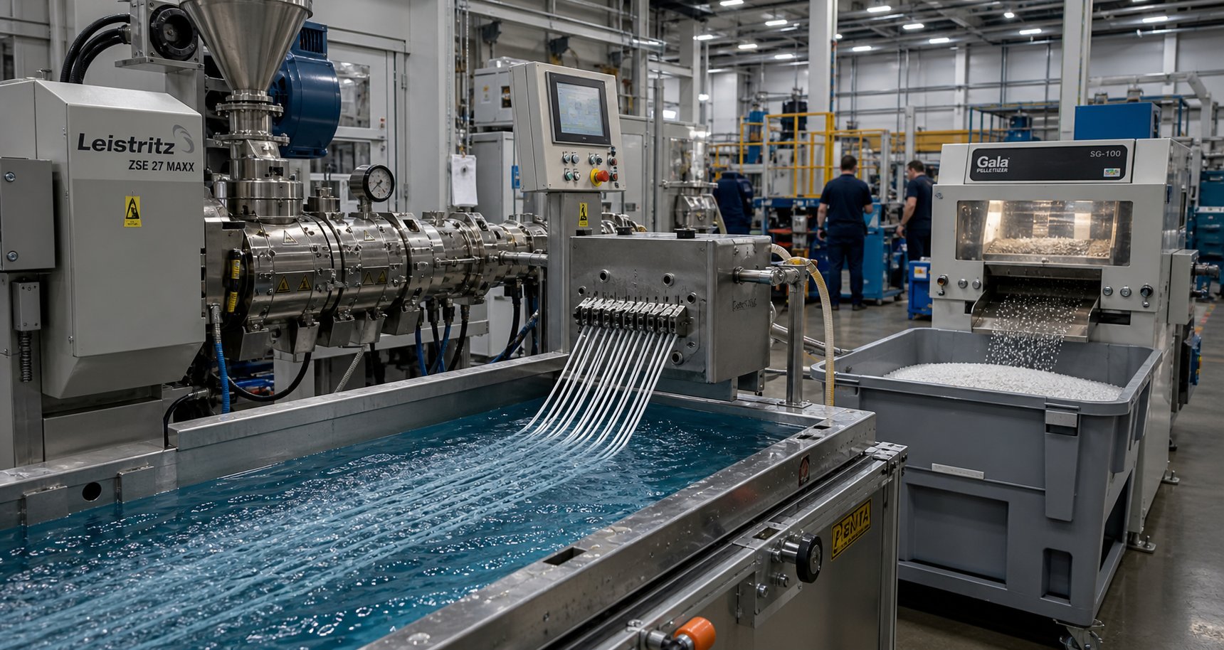
Material-Specific Processing and Industry Applications
Matching machine type to process need is only half the equation. The other half is adapting how the machine runs—screw profile, barrel temperatures, feed strategy, and shear intensity—to the specific material flowing through it. A compounding twin screw extruder processing glass-fiber-filled polypropylene operates under a completely different logic than one dispersing carbon black into a polyethylene masterbatch, even though both might share the same frame, motor, and gearbox. Material dictates process. Ignore that reality, and you'll chase quality problems that no hardware upgrade can solve.
Processing Engineering Plastics and Filled Compounds
Filled compounds are among the most demanding applications for any polymer extruder. The challenge isn't just melting a base resin and pushing it through a die—it's incorporating rigid or abrasive reinforcements without destroying the very properties those reinforcements are supposed to deliver.
Glass-fiber-reinforced thermoplastics illustrate this tension perfectly. Fiber length is the critical quality metric: longer fibers produce stronger, stiffer parts with better impact resistance. But every aggressive kneading block in the screw profile acts like a set of scissors. Research conducted at the University of Kassel and Paderborn University demonstrated that screw configurations containing kneading discs and mixing elements consistently produced shorter glass fibers than configurations relying solely on conveying elements after the fiber feeding zone. The fiber length decreased rapidly within the first few centimeters after the fiber addition point—dropping from 3 mm to under 1 mm within roughly 80 mm of axial screw length when kneading blocks were present. Even more striking, the same screw configuration run on different twin-screw extruders produced different fiber length distributions, suggesting that manufacturer-specific tolerances in screw-to-barrel clearances also influence fiber breakage.
The practical takeaway? When processing fiber-filled compounds on a twin screw compounding extruder, gentler is better. Use narrow-disc kneading blocks at moderate stagger angles—or eliminate them entirely downstream of the fiber feed point—and rely on toothed mixing elements for distributive blending. A screw profile with only conveying elements after fiber addition preserved measurably longer fibers in the study referenced above, even though mixing intensity was lower.
Nano-fillers flip this equation. Materials like nano-clays, carbon nanotubes, and nano-calcium carbonate arrive as tightly bound agglomerates that resist separation. Achieving true nanoscale dispersion demands exactly what fiber-filled compounds avoid: high-shear dispersive mixing with wide-disc, high-stagger-angle kneading blocks. Without sufficient energy input, you'll produce a compound filled with micro-scale clusters that provide none of the surface-area-driven property enhancements nano-fillers promise.
Two feed-system strategies are critical across both filler types:
- Side feeders for downstream addition: Rather than dumping abrasive fillers or fragile fibers into the main feed throat—where they'd travel through every barrel zone including the most aggressive melting sections—side feeders introduce them partway down the barrel after the resin is already molten. This reduces the total shear exposure for fibers and minimizes wear on upstream barrel segments and screw elements. As Nanoscience Instruments notes, side feeders, injectors, or syringes introduce additional components—including solids, liquids, or powders—at controlled points along the barrel to manage exactly this kind of processing sensitivity.
- Liquid injection systems: Plasticizers, coupling agents, reactive silanes, or peroxide initiators often need to enter the melt as precisely metered liquids. Injection nozzles positioned at specific barrel locations deliver these additives directly into the molten stream, where kneading elements downstream ensure rapid incorporation. Coupling agents like maleic anhydride-grafted polypropylene are especially important in glass-fiber compounds—they improve fiber-matrix adhesion, and their effectiveness depends heavily on being introduced at the right barrel temperature and residence time window.
Applications in Recycling, Masterbatch, and Specialty Polymers
The versatility of twin-screw technology extends far beyond engineering plastics. Several major industry sectors rely on the same core platform, each demanding its own tailored approach to screw design, venting, and thermal management.
Plastics recycling represents one of the fastest-growing application areas—and one of the most technically challenging. Post-consumer and post-industrial waste streams arrive with wildly inconsistent composition, moisture content, and contamination levels. A compounding extruder processing recycled HDPE bottles, for example, must handle residual labels, adhesive residue, and trace solvents that would compromise product quality if left in the melt. Coperion's devolatilization technology data shows that twin-screw compounders can reduce volatile organic compounds to remarkably low levels—stripping hexane from LLDPE down from 10-15% to below 500 ppm, or reducing styrene in PS from 3,000-5,000 ppm to under 300 ppm. Adding water as a stripping agent further lowers residual VOC content by an additional 20-35%. Melt filtration screens positioned between the extruder discharge and the pelletizing die catch particulate contaminants, while extended devolatilization zones with multiple vacuum ports handle the volatile removal.
Masterbatch production lives at the opposite end of the precision spectrum. Here, the goal is loading a carrier resin with extremely high concentrations of pigments, additives, or functional fillers—sometimes exceeding 60-70% by weight—while achieving flawless dispersion and consistent pellet quality. A single undispersed pigment agglomerate can create a visible speck in the final molded part, making the entire batch unacceptable. The extruder for polymer masterbatch production typically runs aggressive kneading block sequences to shatter pigment clusters, followed by distributive mixing elements to spread the dispersed particles uniformly. Color consistency between production lots depends on repeatable screw speed, feed rate, and temperature control—any drift in specific energy input shows up immediately as a color shift.
Beyond plastics, twin-screw platforms have carved out essential roles in sectors that demand the same combination of precise thermal control, modularity, and continuous processing:
- Pharmaceutical hot-melt extrusion: Drug molecules with poor water solubility are embedded in polymer carriers at controlled temperatures, creating amorphous solid dispersions that dramatically improve bioavailability. A laboratory twin screw extruder is often the starting point for formulation development, processing just grams of expensive active pharmaceutical ingredients before scaling up. The tight residence time distribution of co-rotating machines ensures uniform drug distribution without thermal degradation of sensitive compounds.
- Food processing: Textured vegetable proteins, breakfast cereals, snack products, and pet food all pass through twin-screw systems. The screws cook, texturize, and shape starch-based or protein-based formulations in a single continuous operation. Temperature precision prevents scorching while achieving the exact degree of gelatinization or protein denaturation the product requires.
- Polyester extruder applications: PET and PBT compounds benefit from twin-screw processing for reactive chain extension, glass-fiber reinforcement, and blending with impact modifiers. Moisture sensitivity makes barrel venting critical—residual water hydrolyzes the polyester backbone, destroying molecular weight and mechanical properties if not removed before the die.
- Biodegradable and bio-based polymers: PLA, PHA, and starch-based blends are inherently sensitive to both temperature and shear. Twin-screw systems provide the narrow processing window these materials require—enough energy to melt and mix without triggering hydrolytic or thermal degradation chains.
Across every one of these sectors, the pattern repeats: the same modular platform adapts to radically different materials by changing screw configuration, barrel layout, feed strategy, and process parameters. That adaptability is what makes twin-screw technology the default choice for any application where the process must do more than simply melt and form.
Yet adaptability cuts both ways. The same flexibility that enables diverse applications also means more variables that can drift out of spec—and when they do, diagnosing the root cause requires a systematic approach to troubleshooting that connects symptoms on the production floor to their origins inside the barrel.
Troubleshooting and Process Optimization for Twin-Screw Extruders
Something changed on the line. Output is surging, torque alarms are firing, or pellets are coming off the strand cutter with visible specks that weren't there yesterday. The screw profile hasn't been touched. The recipe is the same. So what went wrong?
For operators and process engineers running a plastic twin screw extruder day after day, the frustration isn't usually the problem itself—it's figuring out which of a dozen possible causes is the real one. Twin-screw systems have more variables than single-screw machines, which means more potential failure modes. The upside is that those same variables also give you more control levers to pull once you've identified the root cause. Systematic diagnosis, not guesswork, is what separates a quick fix from a week of chasing shadows.
Diagnosing Common Twin-Screw Extrusion Problems
Most production issues on a twin screw plastic extruder trace back to a handful of recurring failure patterns. The trick is reading the symptoms correctly—because two very different root causes can produce nearly identical surface-level effects.
Output surging shows up as fluctuating strand diameter, inconsistent pellet weight, or pulsating die pressure. Operators often blame the extruder first, but the feeder deserves the initial investigation. Gravimetric feeders rely on load cells that drift out of calibration, and material bridging inside the hopper—especially with hygroscopic powders or irregular flake—interrupts the steady mass flow the extruder expects. If the feed rate oscillates, the fill level in the screw channels oscillates with it, and that variation propagates all the way to the die as pressure and output swings. When feeder performance checks out clean, the screw design itself may be the culprit. Insufficient conveying capacity in the feed zone—caused by worn flight tips or an undersized pitch relative to the bulk density of the incoming material—creates a bottleneck that starves downstream sections unevenly.
Torque overload triggers protective shutdowns that halt production entirely. The motor's torque reading reflects how much mechanical resistance the screws encounter, and three conditions drive it beyond safe limits. First, excessive fill level—either from overfeeding or from a downstream restriction like a clogged screen changer—forces the screws to push through more material than the drive can handle. Second, overly aggressive kneading blocks generate intense shear forces that spike the load. An extruder running a 90-degree neutral kneading sequence across multiple barrel diameters will draw significantly more torque than one using 60-degree forward blocks in the same position. Third, insufficient barrel temperature in the melting zone leaves unmelted polymer lumps in the screw channels. Solid particles resist deformation far more than molten material, and their presence creates localized torque peaks that can trip the overload protection. Kerke Extrusion's troubleshooting documentation confirms that highly viscous polymers, highly filled compounds, and abrasive additives all require lower throughput and higher torque thresholds that must be accounted for in operational settings.
Poor dispersion appears as visible agglomerates, streaking in masterbatch strands, or substandard mechanical test results in compounded parts. When pigment clusters or filler agglomerates survive the mixing zone intact, the kneading section isn't delivering enough energy to break them apart. The most common culprits are kneading blocks with insufficient stagger angle—30-degree forward blocks don't generate the shear stress needed for dispersive mixing—or worn kneading elements whose edges have rounded off, reducing the tight tip-to-barrel clearances that create high-shear zones. Increasing screw speed can help by raising shear rate, but it simultaneously shortens residence time in the mixing zone, which may negate the benefit. A more effective fix is often replacing worn mixing elements or adding an additional kneading block section, rather than simply cranking up RPM.
Die build-up is the slow accumulation of degraded polymer, carbonized additives, or crosslinked residue on the die face and inside die orifices. It manifests as gradually declining output, increasingly rough strand surfaces, and eventually strand breakage as partially blocked die holes produce uneven flow. The root cause is almost always thermal—material degrading at the melt temperatures present in the final barrel zones and die adapter. Excessively high melt temperature, driven by over-aggressive kneading blocks or insufficient barrel cooling, accelerates carbonization of heat-sensitive additives. Extended residence time in low-flow regions of the die head compounds the problem. As a practical guideline, optimizing the temperature profile to ensure full melting without overshooting the polymer's stability window—and cleaning the die plate on a scheduled basis—are the two most effective countermeasures.
Process Optimization Using Specific Energy Input
Troubleshooting fixes the immediate problem. Process optimization prevents the next one—and the metric that ties every control variable together into a single actionable number is specific energy input (SEI), expressed in kilowatt-hours per kilogram (kWh/kg).
SEI quantifies how much mechanical energy the motor delivers through the screws into each kilogram of material processed. It captures the combined effect of screw speed, feed rate, and torque in one value. The calculation, as described in a peer-reviewed review published in AAPS PharmSciTech, follows this approach:
SEI = (Motor power x % Torque x RPM running / RPM max x Gearbox efficiency) / Throughput (kg/h)
Why does this matter on the production floor? Because SEI functions as an early-warning system and a quality fingerprint simultaneously. If a formulation consistently runs at an SEI of 0.20 kWh/kg and the value suddenly drops to 0.14 without any intentional process change, something has shifted—feedstock viscosity, filler moisture content, or worn screw elements that no longer transmit energy effectively. Conversely, an unexpected rise to 0.28 might indicate a downstream blockage forcing higher backpressure, or a barrel heater failure leaving the screws to do all the melting work mechanically.
The general optimization principle is intuitive once you see it:
- Too-low SEI means the material isn't receiving enough mechanical work. Symptoms include unmelted particles, poor filler dispersion, and inconsistent melt viscosity. The melt exits the die underprocessed.
- Too-high SEI means the material is absorbing excessive shear energy. Melt temperature climbs beyond the polymer's thermal stability window, triggering degradation, discoloration, molecular weight loss, or crosslinking. The melt exits the die overprocessed.
Three primary control levers allow engineers to dial SEI into the target range for a given formulation:
- Screw speed (RPM): Increasing RPM raises shear rate and energy input directly. It also shortens residence time, which can either help (less thermal exposure) or hurt (less time in mixing zones). Adjusting RPM is the fastest lever to pull, but its effects cascade through every process zone simultaneously.
- Feed rate (kg/h): Raising feed rate at constant RPM increases fill level and reduces specific energy—each kilogram receives less mechanical work. Lowering feed rate does the opposite. This is the primary lever for adjusting SEI without changing shear rate. As Plastics Today's expert analysis explains, higher fill levels also produce a tighter residence time distribution and lower shear per unit mass, while lower fill levels widen the distribution and increase shear exposure.
- Barrel temperature profile: Higher barrel temperatures reduce melt viscosity, which lowers the mechanical energy needed to process the material—effectively reducing SEI. Lower barrel temperatures force the screws to do more of the melting work, increasing SEI. Temperature adjustments are the slowest lever (thermal inertia delays the effect) but the most targeted—you can change a single zone without affecting the rest of the barrel.
Tracking SEI over time—shift by shift, lot by lot—builds a process history that makes anomalies visible immediately. A screw extruder granulator line producing 500 kg/h of filled PP at a consistent 0.18 kWh/kg for six months will reveal a worn screw set long before a quality complaint arrives, simply because the SEI will drift downward as flight clearances widen and energy transfer efficiency drops.
The table below maps the most common production problems to their likely causes and recommended corrective actions, providing a structured diagnostic reference for operators running any twin-screw line:
| Problem | Likely Causes | Recommended Corrective Actions |
|---|---|---|
| Output surging | Feeder calibration drift; hopper bridging; worn feed-zone screw flights; inconsistent feedstock bulk density | Recalibrate gravimetric feeder with production material; install hopper agitator or vibrator; inspect and replace worn conveying elements; pre-blend feedstock to uniform particle size |
| Torque overload | Excessive feed rate relative to screw speed; overly aggressive kneading block sequence; insufficient barrel temperature in melting zone; blocked screen changer or die | Reduce feed rate gradually; replace 90-degree kneading blocks with 60-degree forward blocks; raise melting zone barrel temperature by 10-15 degrees C; clean or replace screen pack and inspect die passages |
| Poor dispersion | Insufficient kneading intensity (low stagger angle); worn kneading element tips; inadequate residence time in mixing zone; excessive feed rate through mixing section | Swap to wider-disc or higher-stagger-angle kneading blocks; measure and replace worn elements exceeding clearance limits; add reverse element upstream of mixing zone to increase fill and dwell time; reduce feed rate at constant RPM |
| Die build-up / strand breakage | Melt temperature exceeding polymer stability; degraded additives carbonizing at die face; extended residence in low-flow die regions; contaminated feedstock | Reduce barrel temperature in final zones and die adapter; shorten kneading section or use narrower-disc elements to lower shear heating; schedule regular die cleaning intervals; improve feedstock screening for contaminants |
| Rising melt temperature | Excessive screw speed; aggressive screw profile generating shear heat faster than barrel cooling can remove; worn barrel cooling channels with restricted flow | Reduce RPM and compensate with increased feed rate to maintain throughput; spread kneading blocks over longer barrel length; flush cooling lines to restore flow rate; verify cooling water temperature and pump pressure |
| Vent flooding | Insufficient melt seal upstream of vent port; reverse element worn or missing; excessive fill level in venting zone; melt viscosity too low for seal geometry | Verify reverse element is present and properly positioned upstream of vent; replace worn reverse elements; reduce feed rate or increase screw speed to lower fill level under vent; adjust barrel temperature to raise melt viscosity in seal region |
| Inconsistent pellet quality | Unstable strand extrusion from die pressure fluctuations; dull pelletizer blades; uneven strand cooling; melt temperature variation | Stabilize die pressure by addressing upstream feed or screw issues; sharpen or replace cutter blades; equalize cooling water distribution across all strands; tighten barrel temperature PID control |
Every row in that table traces a line from production-floor symptom to barrel-level root cause. But notice a recurring theme across many of these corrective actions: worn screw elements, eroded barrel liners, and degraded clearances appear as contributing factors in nearly every failure mode. That pattern points to the topic most production facilities overlook until it's too late—maintenance, wear protection, and knowing when barrel replacement is no longer optional.
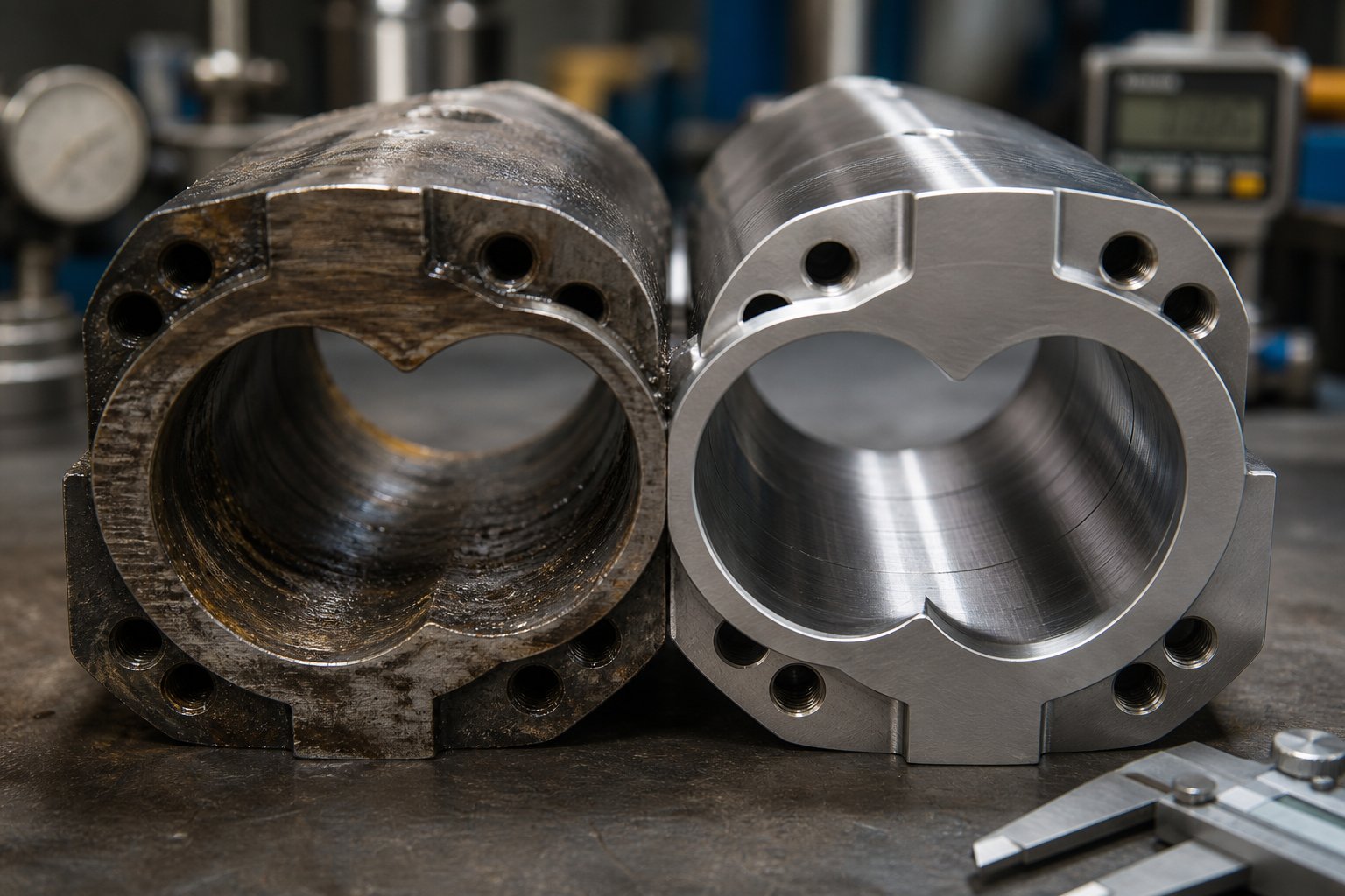
Maintenance, Wear Protection, and Twin Screw Barrel Replacement
Worn screw flights, eroded barrel bores, and widening clearances showed up as contributing factors in nearly every troubleshooting scenario above—and that's not a coincidence. Wear is the slow, invisible process running in the background of every production shift. It doesn't trip an alarm or flash a warning light. Instead, it quietly degrades conveying efficiency, mixing quality, and output consistency over weeks and months until the day you realize the extruder can no longer hold spec. By then, unplanned downtime and emergency part sourcing are already eating into margins.
For operators and maintenance teams, understanding how wear happens, where it concentrates, and what metallurgical defenses are available is the difference between proactive management and reactive firefighting. This section fills that gap.
Understanding Screw and Barrel Wear Patterns
Wear inside a twin screw barrel isn't random. It follows predictable mechanisms, concentrates in specific zones, and produces measurable symptoms long before catastrophic failure. Three distinct wear types dominate:
Abrasive wear is the most common culprit in compounding operations. Every mineral filler, glass fiber, pigment particle, and reinforcing additive acts like fine sandpaper grinding against the barrel wall and screw flight surfaces. Calcium carbonate, talc, titanium dioxide, and especially glass fiber are notorious for accelerating this erosion. Industry documentation on twin-screw wear factors identifies the glass fiber and filler addition zone as one of the most severe wear areas in the entire barrel—long fibers entangle at the feed port, shear during screw rotation, and form sharp fragments that intensify abrasion far beyond what the base polymer alone would produce.
Corrosive wear attacks from a chemical angle. Acidic or halogenated polymers—PVC being the classic example—release hydrochloric acid during processing. Fluoropolymers emit hydrofluoric acid. Flame-retardant formulations containing brominated compounds generate corrosive byproducts at elevated temperatures. These chemicals eat into the barrel's inner surface, pitting the bore and undermining the hard surface layers that are supposed to resist abrasion. Moisture and trapped oxygen inside the barrel compound the problem by accelerating oxidation reactions, particularly under the high-temperature, high-pressure conditions typical of extrusion.
Adhesive wear occurs when metal contacts metal directly. In a properly running extruder, a thin film of molten polymer separates screw flight tips from the barrel wall. But under certain conditions—startup with cold, unmelted material; screw deflection under heavy axial load; or worn elements that have lost their designed clearance geometry—the screw tips physically scrape the barrel bore. Each contact transfers microscopic metal fragments from one surface to the other, scoring both parts and accelerating further deterioration. The feeding zone and discharge zone are particularly vulnerable: in the feed section, solid materials haven't yet formed a lubricating melt film; at the discharge end, the cantilevered screw sags under gravity, causing the screw edge to rub against the barrel's lower bore surface.
How does wear actually manifest on the production floor? You won't see it directly—but you'll feel its effects. As the clearance between screw flight tips and barrel wall widens, several things happen simultaneously:
- Declining output at constant screw speed: Leakage flow through the enlarged gap increases, reducing the net forward pumping efficiency. The extruder moves less material per revolution than it did when the components were new.
- Rising melt temperature: Material recirculating through widened clearances undergoes additional shear cycles, absorbing more energy and heating beyond the target setpoint. You'll notice the melt temperature creeping upward even without changing barrel heater settings or screw speed.
- Loss of self-wiping action: The tight intermeshing geometry that prevents dead zones depends on precise clearances. As flight tips erode, the wiping efficiency drops. Material begins to stagnate in areas that were previously swept clean, leading to degradation, discoloration, and contamination of the product stream.
- Reduced mixing quality: Kneading block effectiveness depends on the high-shear zone between disc tips and the barrel wall. Worn tips widen that gap, reducing shear stress and allowing agglomerates that would previously have been dispersed to survive intact.
A twin screw barrel that has lost just a few tenths of a millimeter in bore diameter can reduce conveying efficiency, degrade mixing quality, and raise melt temperature enough to shift product properties outside specification.
Barrel Metallurgy and Replacement Strategies
Since wear is inevitable, the engineering question becomes: how do you slow it down—and what do you do when replacement becomes unavoidable?
Material selection for the barrel's inner bore is the first and most impactful decision. The right metallurgy matched to your processing conditions can extend barrel life from months to years. The wrong choice can leave you replacing components on an exhausting and expensive cycle. Here's how the major options stack up:
- Nitrided steel (e.g., 38CrMoAlA or 1.8519): The entry-level solution for general-purpose polymer processing. A nitrogen-diffusion treatment hardens the bore surface to approximately 900-1,100 HV, providing adequate resistance for unfilled or lightly filled thermoplastics. Cost-effective and widely available, but insufficient for compounds containing more than modest filler loadings. Best suited for virgin polymer processing with minimal abrasive content.
- Bimetallic liners: A centrifugally cast alloy liner—typically iron-boron-chromium or nickel-chromium-based—bonded inside a structural steel barrel shell. This dual-layer construction delivers 3 to 7 times higher abrasion resistance than standard nitrided barrels, depending on the alloy grade selected. Bimetallic barrels are the workhorse solution for moderately to heavily filled compounds—glass-fiber-reinforced polyamides, mineral-filled polypropylene, and pigment-loaded masterbatch formulations. Because the liner is bonded to a reusable steel shell, worn liners can be replaced without discarding the entire barrel body, reducing long-term replacement costs substantially.
- Tungsten carbide or ceramic-lined barrels: The premium tier, reserved for the most punishing applications—ultra-high glass-fiber loadings (40%+), recycled streams contaminated with metal particles, or highly abrasive mineral fillers like wollastonite and barium sulfate. Tungsten carbide coatings achieve hardness values exceeding 2,000 HV, dramatically outperforming both nitrided and bimetallic options. The trade-off is significantly higher cost and longer lead times for custom-manufactured segments.
- Powder metallurgy (PM) steel elements: An emerging option for screw elements and barrel liners that offers finer, more uniform grain structure than conventionally cast alloys. The controlled production process minimizes segregation of alloying elements like nickel, chromium, and molybdenum, resulting in higher mechanical strength and more consistent wear performance across the entire component surface.
Choosing the right metallurgy isn't just a technical exercise—it's a lifecycle cost calculation. A nitrided barrel processing a 40% glass-fiber-filled PA66 might last eight weeks before clearances exceed tolerance. A bimetallic barrel on the same line could run six months or longer. The upfront price difference pales next to the avoided downtime, labor, and scrap costs of frequent replacements.
Preventive maintenance protocols are what keep wear from becoming a surprise. Experienced twin screw extruder manufacturers universally recommend scheduled bore measurements at defined intervals—typically every 2,000 to 4,000 operating hours for abrasive applications, or every 6,000 to 8,000 hours for less demanding formulations. Coperion's preventive wear diagnostics program demonstrates how this works in practice: with the screws pulled out and the barrel cooled, a bore measurement device and high-resolution camera traverse the process section, imaging the barrel surface in HD and measuring bore diameter at multiple points. For larger machines (screw diameters of 240 mm and above), laser-supported surface measurement maps the entire internal geometry into a three-dimensional model, enabling engineers to identify localized wear patterns and plan targeted repairs before a full barrel replacement becomes necessary.
A practical preventive maintenance schedule for most twin-screw operations should include:
- Every 500-1,000 hours: Visual inspection of screw elements during scheduled shutdowns. Check kneading block tips and conveying element flight edges for rounding, scoring, or material buildup. Measure screw element outer diameters and compare against new-part specifications.
- Every 2,000-4,000 hours: Full barrel bore measurement using precision gauges. Record bore diameter at each barrel segment, paying particular attention to the feeding zone, filler addition zone, and the high-shear kneading sections—the four zones where wear concentrates most aggressively.
- Every 4,000-8,000 hours (or when measurements approach tolerance limits): Evaluate whether individual barrel segments or the full process section require replacement. Single-segment replacement is possible with modular barrel designs, allowing targeted repairs rather than full-line shutdowns.
When bore measurements confirm that a barrel segment has exceeded its wear tolerance—typically defined as a specified percentage increase over the original bore diameter—replacement becomes the only path back to specification-grade production. This is the point where your choice of twin-screw extruder manufacturer or barrel supplier directly impacts recovery time and long-term performance. Sourcing replacement barrels from a specialized manufacturer ensures the new components match the original bore tolerances, metallurgical specifications, and cooling channel configurations your process requires. NANHAIYA, for example, produces custom-engineered parallel twin screw barrels designed for specific wear conditions—supporting compounding, masterbatch, recycling, and pelletizing operations with barrels optimized for stable conveying and high-wear resistance. Partnering with a dedicated barrel manufacturer like this ensures access to metallurgy options matched to your exact processing severity, rather than settling for generic replacement parts that may underperform in demanding applications.
Ultimately, maintenance isn't a cost center—it's a performance strategy. Tracking wear progression with data, selecting barrel metallurgy based on your actual material profile, and replacing components proactively before they compromise product quality is what keeps a twin-screw line running at peak efficiency year after year. The operators who treat their barrel and screw system as a consumable with a predictable lifecycle—rather than a permanent fixture that should last forever—are the ones who consistently hit throughput targets, quality specs, and uptime goals without the chaos of unplanned breakdowns.
Frequently Asked Questions About Twin-Screw Extruders
1. What is the difference between a twin-screw extruder and a single-screw extruder?
A single-screw extruder relies on barrel-wall friction to push material forward and is best suited for melting and forming pre-compounded pellets. A twin-screw extruder uses two intermeshing screws that provide positive displacement, intensive distributive and dispersive mixing, self-wiping action, and modular screw configurations. This makes twin-screw systems the preferred choice whenever a process requires compounding multiple ingredients, devolatilizing contaminants, reactive processing, or handling inconsistent feedstocks like recycled flake and powders. The trade-off is higher capital cost, but the processing flexibility and mixing quality justify the investment for mixing-intensive applications.
2. How do I choose between a co-rotating and counter-rotating twin-screw extruder?
The selection depends on your material and process goals. Co-rotating twin-screw extruders spin both screws in the same direction, generating a figure-eight flow path that delivers high-shear mixing, excellent self-wiping, and broad process flexibility—ideal for compounding, masterbatch, reactive extrusion, and recycling. Counter-rotating extruders spin screws in opposite directions, producing a calendering effect with gentler shear and higher pressure generation—making them the standard for thermally sensitive materials like rigid PVC pipe and profile extrusion. Within counter-rotating designs, intermeshing versions suit PVC processing while non-intermeshing configurations handle high-level devolatilization and shear-sensitive specialty polymers.
3. What is specific energy input (SEI) and why does it matter in twin-screw extrusion?
Specific energy input, measured in kilowatt-hours per kilogram (kWh/kg), quantifies the mechanical energy the extruder motor delivers into each kilogram of processed material. It serves as both a diagnostic fingerprint and an optimization tool. Too-low SEI indicates insufficient melting or mixing, producing unmelted particles and poor filler dispersion. Too-high SEI signals excessive shear that overheats the melt and triggers degradation. Engineers adjust SEI using three control levers—screw speed, feed rate, and barrel temperature profile—and track it over time to detect wear progression, feedstock changes, or process drift before quality problems reach the finished product.
4. How often should twin-screw extruder barrels and screws be inspected for wear?
Inspection frequency depends on the abrasiveness of the materials being processed. For highly filled compounds containing glass fiber or mineral fillers, screw element visual checks every 500 to 1,000 operating hours and full barrel bore measurements every 2,000 to 4,000 hours are recommended. Less abrasive applications can extend bore measurement intervals to 6,000 to 8,000 hours. Key warning signs of excessive wear include declining output at constant screw speed, rising melt temperature without process changes, and deteriorating mixing or dispersion quality. When barrel bores exceed tolerance, sourcing precision-engineered replacement barrels from specialized manufacturers like NANHAIYA ensures restored conveying stability and wear resistance.
5. What barrel metallurgy is best for processing abrasive filled compounds in a twin-screw extruder?
The optimal barrel metallurgy depends on filler type, loading level, and processing severity. Nitrided steel suits general-purpose unfilled or lightly filled polymer processing at the lowest cost. Bimetallic liners—centrifugally cast iron-boron-chromium or nickel-chromium alloys inside a structural steel shell—deliver 3 to 7 times higher abrasion resistance and are the standard for moderately to heavily filled compounds like glass-fiber polyamides and mineral-filled polypropylene. Tungsten carbide or ceramic-lined barrels handle the most extreme applications, including ultra-high glass-fiber loadings above 40% or metal-contaminated recycled feedstocks. Choosing correctly is a lifecycle cost decision: a bimetallic barrel may cost more upfront but can outlast a nitrided barrel by months in abrasive service.
Written by
Nanhaiya Technical Team
Zhoushan Nanhaiya Plastic Machinery Co., Ltd.
The Nanhaiya technical team supports screw and barrel manufacturing projects through application review, technical communication, custom manufacturing coordination, and production and quality control.
Discuss Your Application
Related Articles
More insights on screw barrel technology and plastics processing.

What Nobody Tells You About Screw Barrel For Plastic Machine Design
Oct 10, 2026
Learn how screw barrel for plastic machine design affects melt quality, throughput, and wear life. Covers geometry, resin matching, troubleshooting, and sourcing.
Read Article
Single Screw Extruder for Sheet: Stop Guessing, Start Specifying
Oct 9, 2026
Learn how to specify a single screw extruder for sheet production. Covers screw geometry, resin-specific processing, troubleshooting, and maintenance best practices.
Read Article
PE Pipe Extruder Machine: What Datasheets Won't Tell You
Oct 9, 2026
Learn how a PE pipe extruder machine works, key specs explained, material grade selection, maintenance tips, and buyer guidance beyond the datasheet.
Read ArticleLooking for something else?
Search by material, symptom or product and jump straight to the relevant page.
These are navigation suggestions based on keyword matching — not a quotation, not a delivery commitment, and not a substitute for engineering review. Final specification is confirmed by our engineers against your drawings and processed material.
Need help with screw barrel selection?
Share your machine model, processed material and application. Our team can help with pricing and technical support.