

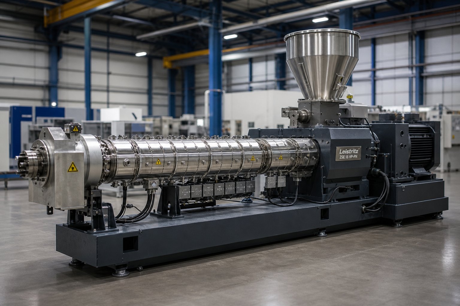
What Is a Twin-Screw Extruder Machine and Why It Matters
A twin-screw extruder machine is a high-performance processing system that uses two intermeshing screws rotating inside a heated, segmented barrel to convey, melt, mix, and shape polymer and non-polymer materials into finished or semi-finished products. It is the workhorse behind modern compounding, masterbatch production, pelletizing, plastic recycling, and profile extrusion - and for good reason. No other single piece of equipment offers the same combination of mixing intensity, process flexibility, and feedstock versatility in a continuous operation.
If you already know the basics, this article is built for you. Rather than rehashing introductory concepts, the sections ahead break down every engineering dimension that matters: screw element selection and sequencing, co-rotating versus counter-rotating configurations, critical technical specifications like L/D ratio and torque density, process parameter interactions, material-specific screw design strategies, and real-world troubleshooting. Consider it a technical reference for process engineers, production managers, and informed buyers who need depth, not just definitions.
What a Twin-Screw Extruder Machine Actually Does
At its core, a twin screw extruder performs five sequential functions along the length of its barrel:
- Feeding - Raw material, whether pellets, powder, flakes, or liquids, enters the barrel through a hopper or side feeder and is picked up by the rotating screws.
- Melting (Plasticizing) - A combination of barrel heat and mechanical shear from the screw elements converts solid feedstock into a molten or semi-molten state.
- Mixing - Specialized screw elements, particularly kneading blocks, deliver intensive dispersive and distributive mixing to homogenize additives, fillers, pigments, or blended polymers throughout the melt.
- Devolatilization - Venting or vacuum zones along the barrel remove moisture, trapped air, and volatile compounds from the melt, which is critical for product quality and surface finish.
- Pumping (Metering) - The final screw section builds pressure to push the homogenized melt through a die or into downstream equipment like a pelletizer or calibration tool.
Each of these stages can be fine-tuned independently, and that brings us to the single most important characteristic of the twin screw extruder:
The modularity of screw and barrel design enables virtually infinite process customization. By rearranging, swapping, or replacing individual screw elements and barrel segments, engineers can reconfigure the same machine for entirely different materials and applications without purchasing new equipment.
Why Twin-Screw Technology Dominates Modern Plastics Processing
Imagine trying to uniformly disperse 40% calcium carbonate filler into a polypropylene matrix, or devolatilize moisture from recycled PET flakes, using a single-screw extruder. You'll quickly hit limitations. Single-screw machines rely primarily on drag flow to move material forward, which limits their mixing intensity and makes them less effective at handling diverse or difficult feedstocks.
A twin screw extruder machine changes the equation in three fundamental ways. First, the intermeshing screw geometry creates a self-wiping action that continuously scrapes material off barrel walls and screw surfaces, preventing stagnation and thermal degradation. Second, the ability to incorporate aggressive kneading blocks and mixing elements delivers far higher shear and mixing intensity than any single-screw design can achieve. Third, the starve-fed operation typical of co-rotating designs decouples feed rate from screw speed, giving operators independent control over residence time, fill level, and specific energy input.
These advantages explain why twin-screw technology has become the default for compounding, reactive extrusion, masterbatch production, and recycling operations worldwide. The question for most engineers and buyers is not whether to use a twin-screw extruder, but which configuration, screw design, and process settings will deliver the best results for their specific material and application - and that is exactly what the following sections address.
Co-Rotating vs Counter-Rotating Twin-Screw Extruders Compared
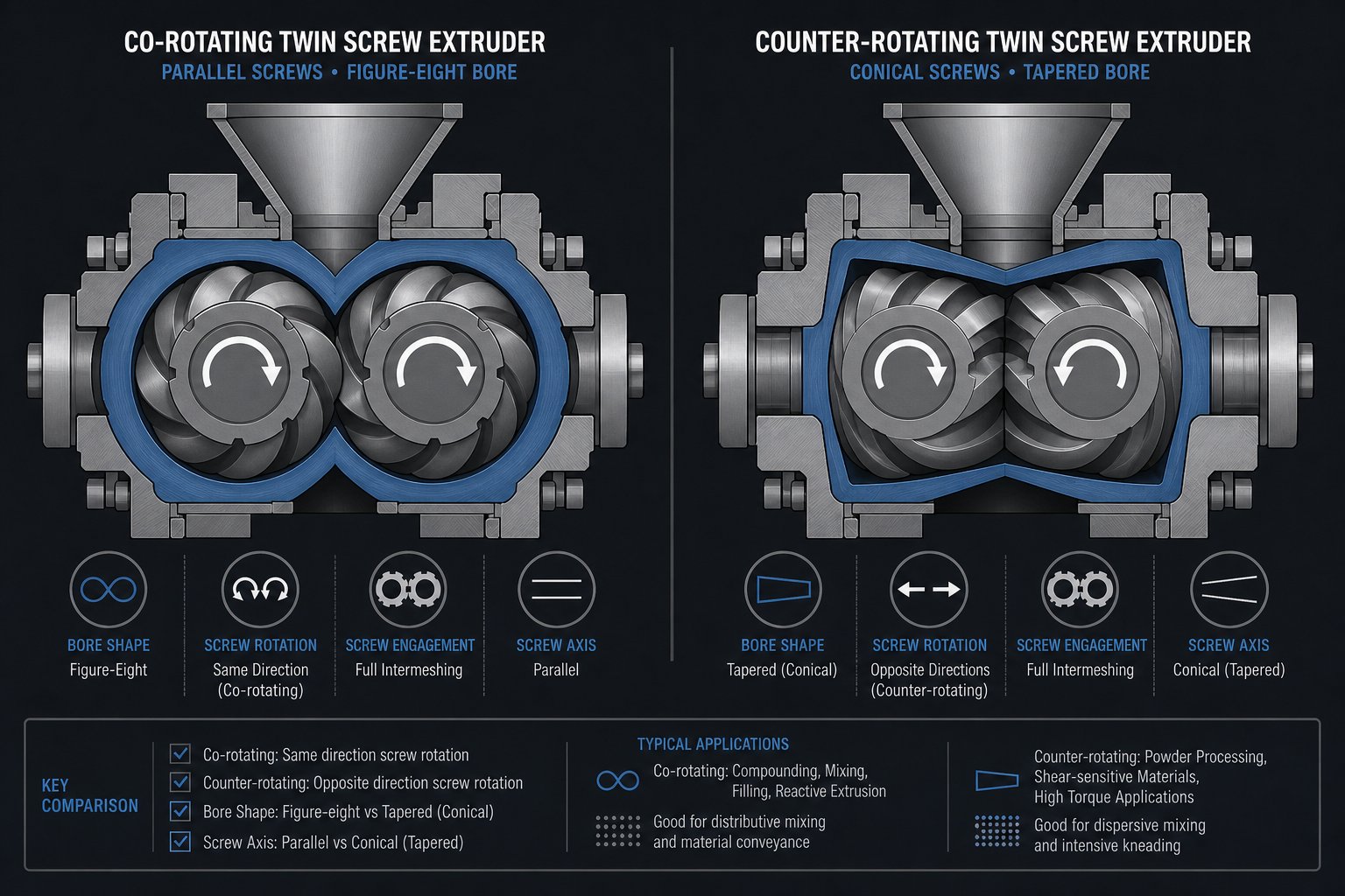
Configuration choice shapes everything downstream - mixing quality, thermal control, throughput, and even which materials you can process reliably. Twin screw extruders split into two principal categories based on how the screws rotate relative to each other: co-rotating, where both screws turn in the same direction, and counter-rotating, where they turn in opposite directions. The differences in screw geometry that result from this single design decision produce dramatically different flow fields, shear profiles, and processing characteristics. Understanding the distinction between a co rotating and counter rotating twin screw extruder is the first real decision point in any equipment selection process.
Co-Rotating Twin-Screw Extruders and Their Strengths
In a co rotating twin screw extruder, both screws rotate in the same direction using a fully intermeshing geometry. Picture material being forcibly handed off from one screw flight to the next at the intermeshing zone - this creates a powerful self-wiping action that continuously scrapes polymer from every surface. The result? Very few dead zones inside the barrel, a narrow residence time distribution, and minimal risk of material stagnation or thermal degradation.
The mixing performance of co-rotating designs is where they truly separate from other configurations. Intense shear fields develop both between the two screws and between each screw and the barrel wall. Add kneading blocks into the screw profile, and you introduce an elongational flow component that works alongside the shear forces. Together, these mechanisms impose a complex deformation history on the material - exactly what you need for breaking down filler agglomerates, controlling phase morphology in polymer alloys, or driving chemical reactions in reactive extrusion.
This combination of high-shear dispersive mixing, modular screw element flexibility, and self-wiping capability makes co-rotating extruders the dominant choice for:
- Compounding with inorganic, organic, and nanoscale fillers
- Polymer alloy and blend production
- Masterbatch manufacturing
- Reactive extrusion involving polymerization or compatibilization
- Devolatilization and recycling operations
The trade-off? All that shear intensity generates heat. For materials with narrow thermal processing windows, a co-rotating twin screw can work against you if screw design and operating parameters are not carefully managed.
Counter-Rotating Configurations for Pressure-Sensitive Applications
Flip one screw's rotation direction, and the processing physics change substantially. In a counter-rotating twin screw extruder, the screws turn in opposite directions, drawing material into the intermeshing region and advancing it forward under compression. Material transport depends heavily on screw rotation itself, enabling stable extrusion even at comparatively low rotational speeds and under high fill conditions.
Mixing here does not rely on the aggressive shear stress typical of co-rotating machines. Instead, a calendering effect appears at the intermeshing zone, where material undergoes repeated compressive and elongational deformation under relatively gentle conditions. Shear heating stays low, and extrusion temperatures can be held well below what a co-rotating design would produce at similar throughput.
This makes counter-rotating extruders the clear choice for materials like rigid PVC, which combines a low thermal decomposition temperature with poor melt flow. High shear would degrade PVC before you could form it into anything useful. Counter-rotating designs allow the extrusion temperature to stay low through high-fill, low-speed operation - which is exactly why this configuration dominates PVC pipe, sheet, and profile extrusion worldwide.
Counter-rotating twin screw extruders come in two distinct geometries:
- Parallel counter-rotating - The screws maintain a constant diameter along their length, similar to co-rotating machines. A parallel twin screw extruder in counter-rotating mode suits compounding tasks where moderate shear and strong positive conveying are both needed.
- Conical counter-rotating - The screws taper from a larger diameter at the feed end to a smaller diameter at the discharge end. A conical twin screw extruder provides enhanced feeding capability for bulky or low-bulk-density materials, while the tapering geometry naturally builds pressure toward the die. This design is particularly well established for PVC pipe and profile extrusion, where stable pressure generation and gentle processing are essential.
Decision Matrix for Choosing the Right Configuration
Selecting between co rotating and counter rotating twin screw extruder configurations comes down to matching machine characteristics to your material, application, and processing priorities. The table below organizes the key decision parameters across all three common geometries - giving you a side-by-side comparison that clarifies when each design delivers its best performance.
| Parameter | Co-Rotating (Parallel) | Counter-Rotating (Parallel) | Counter-Rotating (Conical) |
|---|---|---|---|
| Typical Applications | Compounding, masterbatch, reactive extrusion, polymer alloys, recycling | Moderate-shear compounding, specialty formulations | PVC pipe and profile extrusion, PVC sheet, heat-sensitive polymer forming |
| Shear Level | High | Low to moderate | Low |
| Mixing Intensity | High (dispersive and distributive) | Moderate (calendering-based dispersion) | Moderate (gentle compressive mixing) |
| Throughput Range | Broad (lab scale to several thousand kg/h) | Moderate | Moderate (optimized for forming rather than maximum throughput) |
| Self-Wiping Capability | Excellent - fully self-wiping geometry | Limited | Limited |
| Ideal Material Types | Polyolefins, engineering plastics, filled compounds, polymer blends, recycled resins | Moderately shear-sensitive compounds, specialty formulations | PVC (rigid and flexible), heat-sensitive bioplastics, low-melt-flow polymers |
| Pressure Generation | Moderate (often paired with gear pump for high-pressure needs) | Good (positive conveying action) | Good (taper geometry builds pressure naturally) |
| Residence Time Control | Precise (starve-fed operation decouples feed rate from screw speed) | Moderate | Moderate |
| Relative Equipment Cost | Moderate to high | Moderate | Moderate (simpler drive systems in some designs) |
A quick rule of thumb: if your primary goal is intensive mixing, filler dispersion, or reactive processing, the co-rotating configuration is almost always the starting point. If you are forming PVC or processing materials that degrade under high shear, counter-rotating - especially conical - is where you should focus your evaluation.
Of course, choosing the right twin screw configuration is only the beginning. The real performance of any extruder lives in its screw elements - the individual building blocks that determine exactly how material is conveyed, sheared, kneaded, and pressurized at every point along the barrel. That element-level engineering is where process outcomes are truly defined.
Screw Element Design and Configuration Strategies
Every extruder screw profile is essentially a recipe. Individual screw elements are the ingredients, and the order you place them along the shaft determines whether your process delivers perfectly dispersed compounds or inconsistent, degraded output. Surprisingly, most technical resources skip this level of detail entirely - leaving engineers to piece together screw configuration logic through trial and error. That gap ends here.
Configuring a screw profile is, as NC State Extension research describes it, "a blend of art and science." No universal standard exists because every material exhibits unique flow properties influenced by temperature, shear rate, and extruder geometry. However, the underlying logic of element selection follows clear functional principles that every process engineer should internalize.
Types of Screw Elements and What Each One Does
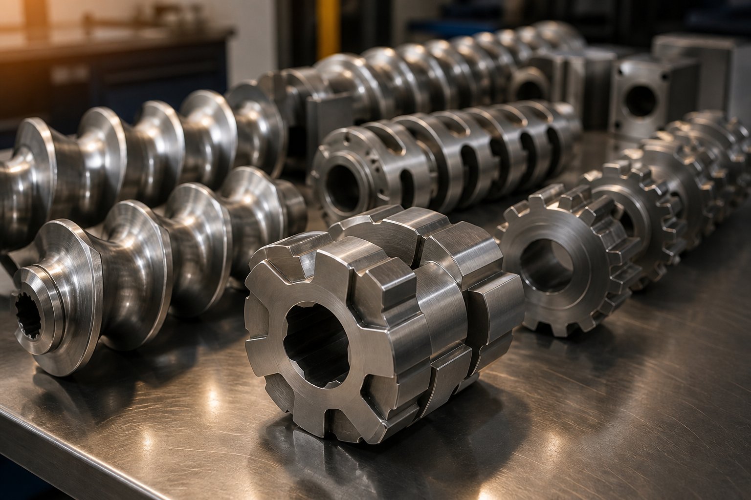
An extruder twin screw assembly is built from modular elements that slide onto a splined shaft. Each element category serves a distinct processing function, and its geometry directly controls how material experiences residence time, shear intensity, and pressure as it moves through the barrel.
- Forward-pitch conveying elements - These are the workhorses of material transport. Deep-flighted designs move material forward efficiently without imparting significant shear. Increasing the pitch raises conveying speed but reduces pressure buildup; decreasing pitch does the opposite. You'll find these elements dominating the feed zone and metering zone of virtually every screw profile.
- Reverse-pitch conveying elements (re-conveying elements) - These push material backward against the flow direction, creating a restriction that increases local fill level and residence time. Engineers place them strategically to build pressure seals upstream of venting zones or to intensify mixing in specific barrel sections.
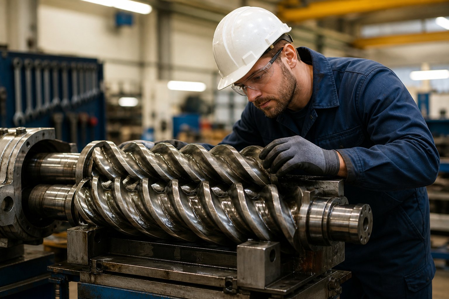
- Kneading blocks - The primary mixing workhorses. Kneading blocks consist of multiple lobed discs stacked at stagger angles along the shaft. According to published research on screw functionality, wider kneading elements promote dispersive mixing - breaking down agglomerates through strong shear stress - while narrow kneading elements contribute more toward distributive mixing, spreading the dispersed phase evenly without particle breakdown. The stagger angle matters just as much: forward-staggered kneading blocks are less aggressive and maintain some conveying action, neutral (90-degree) blocks halt forward flow and maximize energy input, and reverse-staggered blocks push material backward for maximum restriction and shear intensity.
- Toothed mixing elements (TME, ZME) - These gear-like elements feature rows of teeth that split and recombine flow streams repeatedly. They deliver strong distributive mixing with minimal shear stress, making them ideal for blending heat-sensitive additives or achieving uniform color dispersion without thermally degrading the polymer matrix.
- Specialty elements - This category includes open-flight designs for devolatilization zones that maximize melt surface area for volatile removal, as well as elements engineered to accommodate side feeders for downstream introduction of fillers, fibers, or liquid additives. Some specialty elements also serve as melt seals that isolate vacuum zones from atmospheric barrel sections.
The interplay between these element types is what makes the extruder screw profile so powerful - and so demanding to get right. A single misplaced kneading block can spike melt temperature by tens of degrees. A reverse element positioned too aggressively can cause torque overloads at startup.
Building a Screw Configuration for Specific Processing Goals
Imagine walking along the barrel from the feed throat to the die. Each zone you pass through has a specific job, and the screw elements in that zone must be selected and sequenced to accomplish it.
The feed zone uses deep-flight, high-pitch conveying elements. The goal here is simple: pull material in and move it forward as quickly as possible without compacting or melting it prematurely. Starve-fed operation keeps this zone partially filled, preventing backflow into the hopper.
Transitioning into the plasticizing zone, the element profile shifts from conveying to kneading. Forward-staggered kneading blocks begin softening and melting the material through a combination of barrel heat and mechanical shear. As material progresses, you may encounter neutral or reverse-staggered kneading blocks that intensify mixing - breaking down filler agglomerates in compounding applications or achieving phase dispersion in polymer blends. The length and aggressiveness of this kneading section must be calibrated to the material: too little and you get undispersed particles; too much and you risk thermal degradation.
A devolatilization zone often follows, featuring open-flight conveying elements under a barrel vent or vacuum port. Reverse elements placed just upstream create a melt seal that prevents vapor from escaping backward. The melt spreads into thin films across the screw flights, exposing maximum surface area for moisture and volatile removal.
The metering zone at the barrel's end uses shallow-pitch conveying elements that compress the melt and build the pressure needed to push material through the die. Consistency here is critical - pressure fluctuations in this zone translate directly into dimensional variation in the final product.
What ties this entire approach together is modularity. The twin screw barrel is segmented into individual barrel sections that bolt together, and the screw elements slide onto the shaft in any sequence the engineer specifies. You can rearrange, replace, and swap individual elements without replacing the entire screw assembly. Need to add a second kneading zone for a more demanding compound? Slide in additional kneading blocks and adjust the adjacent conveying elements. Switching from a filled polyolefin to an unfilled engineering plastic? Reconfigure the same machine in hours rather than purchasing a new one.
This modularity, however, only delivers its full value when every extruder screw and barrel component is manufactured to tight tolerances. Worn elements lose their self-wiping clearance, degrading mixing efficiency and creating dead zones where material can stagnate and thermally decompose. Barrel liners that have lost their dimensional accuracy allow melt leakage past the screw flights, reducing pumping efficiency and destabilizing output.
That reality makes the supply chain for precision screw and barrel components just as important as the initial machine selection. Specialized suppliers like NANHAIYA provide extruder screw and barrel support engineered specifically for pipe, profile, sheet, pelletizing, and recycling extrusion lines - enabling production teams to reconfigure, maintain, and restore their twin screw barrel and screw assemblies without depending solely on the original equipment manufacturer. This kind of modular supply chain access is what keeps extrusion lines running at peak consistency, even as screw elements wear and processing requirements evolve.
The screw configuration is arguably the single most impactful engineering decision in twin-screw extrusion - yet it remains one of the least documented. Mastering element selection and sequencing is what separates routine processing from truly optimized output.
Element-level design governs what happens inside the barrel. But how do you quantify the machine's overall capability before a single element is placed on the shaft? That question leads directly to the technical specifications - L/D ratio, screw diameter, torque density, and temperature zone architecture - that define the performance envelope every screw configuration must operate within.
Critical Technical Specifications Engineers Must Understand
Screw element selection determines what happens to material inside the barrel - but the barrel itself, the drive system, and the thermal architecture define the boundaries of what is even possible. Think of it this way: you can design the most sophisticated screw profile in the world, but if the machine lacks the torque to turn it, the barrel length to execute every processing stage, or the thermal control to hold a precise melt temperature, that profile never reaches its potential.
This is where technical specifications matter. For process engineers evaluating twin screw extruders and for buyers comparing double screw extruder options across manufacturers, a handful of key specs separate machines that merely run from machines that consistently produce high-quality output. Let's break each one down.
L/D Ratio and Its Impact on Processing Capability
The length-to-diameter ratio - written as L/D - expresses how long the barrel is relative to the screw diameter. A machine with a 40 mm screw diameter and 1,600 mm functional barrel length has an L/D of 40:1. Simple math, but the processing implications are anything but simple.
A higher L/D ratio gives you more barrel real estate. That extra length translates directly into more functional zones: additional kneading sections for intensive mixing, dedicated devolatilization stages for moisture or volatile removal, and extended metering zones for pressure stabilization. As research on screw parameters confirms, enhanced L/D ratios combined with optimized thermal gradients facilitate superior polymer blending and plasticization, because the extended residence time within the barrel allows more comprehensive heat distribution throughout the material.
However, longer is not automatically better. Increasing the L/D ratio also increases power consumption, manufacturing precision requirements, and the risk of shaft deflection - where the screw bows slightly under its own weight and operational loads, potentially scoring the barrel wall. For thermally sensitive polymers like PVC, a shorter L/D ratio is generally preferred because extended residence time raises the risk of thermal degradation.
Here is a practical way to think about L/D selection:
- Lower L/D values (around 20:1 to 28:1) - Suitable for simpler compounding tasks, pre-pelletized materials that melt easily, and heat-sensitive polymers where minimizing residence time is critical.
- Moderate L/D values (around 32:1 to 36:1) - The most common range for general-purpose compounding, masterbatch production, and moderate devolatilization requirements.
- Higher L/D values (40:1 and above) - Required for complex multi-stage processes: reactive extrusion, aggressive devolatilization, high-filler-loading compounding, and applications where multiple side feeders introduce downstream ingredients that need additional mixing length.
The number of barrel zones maps directly to L/D ratio. Each barrel section typically contributes a fixed length, so a higher L/D machine simply has more individually controllable barrel segments - and more opportunities to place vents, side feeders, and liquid injection ports along the processing path.
Screw Diameter, Speed, and Torque Ratings
If L/D ratio determines how much processing you can fit into the barrel, screw diameter determines the scale at which that processing happens. Larger screws process more material per revolution - and the relationship is not linear. As gearbox engineering data illustrates, extrusion volume is roughly proportional to the square of the screw diameter, so even a modest increase in diameter yields a substantial rise in throughput capacity.
Twin-screw extruders span an enormous diameter range - from laboratory-scale machines with screws as small as 16 mm to production-scale twin-screw extruders with diameters exceeding 130 mm. The diameter you need depends on your target throughput, but the mechanical consequences of that choice ripple through every other specification.
Screw speed, measured in RPM, controls the shear rate imposed on the material and the rate at which it moves through each processing zone. Increasing RPM raises shear intensity and throughput potential, but it also shortens residence time and generates more viscous dissipation (frictional heat). For shear-sensitive or thermally delicate materials, you'll often run at lower speeds to avoid degradation - which means the machine needs enough torque to maintain rotational force even at reduced RPM.
And that brings us to the specification that arguably matters most for a double screw extruder machine: specific torque density. Measured in Nm/cm3, torque density relates the gearbox's torque output to the cross-sectional area of the screws it drives. It is the truest measure of an extruder's mechanical capability because it normalizes for screw size and tells you how much rotational force the machine can deliver per unit of screw volume.
Modern high-performance twin-screw extruders achieve torque densities of up to 18 Nm/cm3, representing roughly a 30% increase over previous-generation machines. This higher torque density enables processing of materials - like glass-filled polyamide and heavily loaded mineral compounds - that would have been torque-limited on older equipment. Standard machines typically operate in the 5-10 Nm/cm3 range, while high-torque designs exceed 10 Nm/cm3.
A reliable operating guideline: run at roughly 80% of maximum continuous torque and 80% of maximum speed. This margin provides headroom for process variations, startup transients, and cold-material surges without risking gearbox damage.
Temperature Zone Control and Throughput Capacity
Imagine trying to bake bread in an oven with a single temperature setting for the entire cavity. You'd burn the crust and undercook the center. Twin-screw extrusion faces the same challenge - different barrel zones need different thermal conditions, and the barrel is divided into multiple zones, each with independent temperature control, to achieve precise melt temperature profiles along the entire processing path.
Each barrel section typically incorporates electric heater bands for heating and internal cooling channels (water or oil circulation) for removing excess heat. In the feed zone, barrels are usually cooled to prevent premature melting and bridging. The plasticizing and mixing zones are heated to promote melting and reduce melt viscosity. The metering zone may need cooling to counteract the viscous dissipation from shear-intensive screw elements.
The key insight is that barrel temperature and actual melt temperature are not the same thing. Particularly in the mixing zones of twin-screw extruders, the mechanical energy from kneading blocks generates significant frictional heat within the polymer melt - a phenomenon called viscous dissipation. In high-speed, high-shear operations, the melt temperature can exceed the barrel set point by a substantial margin. This is why barrel cooling is just as important as barrel heating: you need the ability to pull heat out, not just add it in.
Throughput capacity ties everything together. The volume of material a twin-screw extruder can process per hour is a function of screw diameter (which sets the channel volume), screw speed (which determines how many times per minute that volume moves forward), and the bulk density of the feed material (which determines how much mass actually fills the available screw channel volume). Powders, with their low bulk density, fill screw channels less efficiently than pellets, which means powder-fed processes often require larger-diameter screws or higher screw speeds to achieve the same mass throughput.
The table below organizes all of these specification categories into a single reference that links each parameter to what it controls and why it matters for process outcomes.
| Specification | What It Controls | Why It Matters for Process Outcomes |
|---|---|---|
| L/D Ratio | Available barrel length for functional zones (mixing, devolatilization, reaction, metering) | Determines how many processing stages can be accommodated; higher values enable complex multi-step operations but increase residence time and power demand |
| Screw Diameter | Throughput scale and channel volume per revolution | Sets the production capacity baseline; larger diameters process more material but require proportionally higher torque (roughly cubic relationship) |
| Screw Speed (RPM) | Shear rate, conveying speed, and residence time | Higher speeds increase throughput and shear intensity but shorten residence time and raise melt temperature through viscous dissipation |
| Specific Torque Density (Nm/cm3) | Maximum rotational force available per unit screw cross-section | Defines the mechanical ceiling for processing high-viscosity, highly filled, or otherwise torque-demanding materials; insufficient torque density limits throughput and material range |
| Number of Barrel Zones | Temperature profile resolution and placement flexibility for vents, feeders, and injection ports | More zones provide finer thermal control and greater flexibility to configure side-feed, venting, and liquid injection locations along the barrel |
| Barrel Temperature Range | Heating and cooling capacity per zone | Must cover the full processing window of target materials; cooling capacity is often the limiting factor in high-shear operations where viscous dissipation dominates |
| Throughput Capacity (kg/h) | Mass output rate achievable under specific screw speed, fill level, and material conditions | Must match downstream equipment capacity (pelletizer, die, cooling system); influenced by screw diameter, speed, and feed material bulk density |
| Do/Di Ratio (Outer/Inner Screw Diameter) | Free volume in screw channels and shaft strength | Higher ratios provide more channel volume for throughput but reduce shaft cross-section and torque capacity; a ratio of approximately 1.55 balances high-torque applications |
These specifications do not operate in isolation. Raising the L/D ratio on a given screw diameter increases the torque demand on the gearbox. Boosting screw speed amplifies both throughput and viscous dissipation, shifting the burden onto the barrel cooling system. Selecting a larger screw diameter multiplies throughput but also multiplies the torque requirement by roughly the cube of the diameter change. Every specification interacts with every other - and those interactions extend beyond the machine's nameplate into the process parameters that operators control in real time: screw speed, feed rate, and barrel temperature profile.
Process Parameters and How They Shape Output Quality
Specifications tell you what a machine can do. Process parameters determine what it actually does on any given production run. Two identically specified twin screw extruders running the same material can produce dramatically different output quality depending on how three controllable variables are set: screw speed, feed rate, and barrel temperature profile. For process engineers working in twin screw extrusion, mastering these parameters - and understanding how they interact - is the difference between consistent, first-pass quality and hours lost to trial-and-error adjustment.
How Screw Speed and Feed Rate Work Together
Here is a concept that trips up many operators: in a starve-fed co-rotating extruder, screw speed and feed rate are independently controllable. The output rate is set by the feeder, not the screws. The screws simply process whatever material the feeder delivers. This decoupling is fundamental to the twin screw extrusion process and is what makes these machines so tunable.
The ratio between feed rate and screw speed determines the fill ratio - the percentage of available screw channel volume that actually contains material at any given moment. A lower fill ratio (less material, higher screw speed) means material spends more time exposed to shear-intensive mixing elements and experiences higher specific energy input. A higher fill ratio (more material, lower screw speed) produces tighter residence time distribution with less shear per unit of material.
Feeders themselves come in two categories, each with different implications for process stability:
- Volumetric feeders deliver material at a constant volume per unit time. They are simpler and less expensive but cannot compensate for changes in material bulk density - meaning actual mass flow fluctuates if pellet size, moisture content, or powder packing varies.
- Gravimetric (loss-in-weight) feeders continuously weigh the hopper and adjust feed speed to maintain a constant mass flow rate. They deliver far better process consistency, especially with powders, flakes, or recycled feedstocks where bulk density varies significantly.
What happens when you increase screw speed while holding feed rate constant? The fill ratio drops, residence time shortens, and shear rate rises. The material passes through kneading zones faster but experiences more intense deformation during each pass. Specific energy - the amount of motor power input per kilogram of material - shifts accordingly. Tracking specific energy over time provides one of the best diagnostic tools available: if a product that normally runs at a certain specific energy suddenly drops or spikes while hardware and settings remain unchanged, the feedstock itself has likely changed.
Barrel Temperature Profile Strategies
The barrel temperature profile - the sequence of zone setpoints from feed throat to die - shapes how and where the polymer melts, what viscosity the melt reaches in each processing zone, and how much thermal headroom remains before degradation begins. Three common profile strategies cover most screw extrusion applications:
- Ascending profile - Zone temperatures increase progressively from feed end to discharge. This approach suits materials that benefit from gradual melting and reduced viscosity toward the die, such as certain polyolefin compounds where you want the melt as fluid as possible for pelletizing or sheet extrusion.
- Descending profile - Temperatures start high in the melting zone and decrease toward the discharge. This strategy is common for engineering plastics and shear-sensitive materials where early, complete melting is desirable, but you need to pull heat out of the melt downstream to prevent thermal degradation caused by viscous dissipation in the mixing and metering zones.
- Humped (bell-curve) profile - Temperatures peak in the middle of the barrel and drop at both ends. This profile works well for reactive extrusion or processes where maximum mixing intensity occurs mid-barrel and you need cooler conditions in both the feed zone (to prevent bridging) and the discharge zone (to control melt temperature at the die).
A critical nuance that separates experienced engineers from operators following set-point recipes: barrel temperature and melt temperature are not the same thing. In the mixing zones of screw extruders, kneading blocks and mixing elements convert mechanical energy into frictional heat within the polymer - viscous dissipation. At high screw speeds or with high-viscosity melts, this internally generated heat can push actual melt temperature well above the barrel wall setpoint. The barrel cooling system then works to extract that excess energy. In practice, many high-speed compounding operations run with barrel cooling active in the mixing zones even while the setpoint reads well above ambient - because the melt itself is generating more heat than the setpoint would suggest.
The Interaction Effect on Output Quality
This is where twin screw extrusion gets genuinely complex - and genuinely rewarding for engineers who invest the time to understand it. Screw configuration, speed, feed rate, and temperature profile are not independent levers. Pulling one shifts the optimal setting for every other.
Consider a practical scenario. You increase screw speed to improve filler dispersion. The higher shear does break down more agglomerates, but it also raises melt temperature through viscous dissipation. To compensate, you lower barrel temperature setpoints in the mixing zone. That reduces barrel-side heat input but may also slow melting in the plasticizing zone, meaning the material arrives at the kneading blocks only partially molten - which increases torque demand and may trigger a torque overload. One adjustment cascades into the next.
The same cascade applies in reverse. Increasing feed rate at constant screw speed raises fill ratio, which improves throughput but reduces specific energy input per kilogram. If the material needs a minimum energy input for adequate mixing, increasing feed rate without also increasing screw speed produces under-dispersed output. Technical analysis from Leistritz confirms this dynamic: feed rate versus screw RPM, combined with the screw design and temperature profile, regulates the mass transfer and mixing properties of the process. Highly dispersive mixing applications run at comparatively lower throughput rates because the material needs to spend more time in zones where shear effects and extensional flow fields dominate.
In twin-screw extrusion, process optimization is always multivariate - no single parameter can be tuned in isolation.
This principle is what makes process engineering in twin screw extrusion as much about systematic thinking as it is about mechanical knowledge. Operators who adjust one variable at a time and wait for results will eventually find a workable setting - but they will rarely find the optimal one. Engineers who understand the interaction map between screw speed, fill ratio, specific energy, barrel temperature, and melt temperature can move through the optimization space far more efficiently, reaching stable, high-quality operating points in a fraction of the time.
These parameter interactions play out differently depending on the polymer you are processing. A setting that delivers excellent dispersion in a polyolefin compound may cause catastrophic degradation in PVC or a heat-sensitive bioplastic. The material itself introduces another layer of constraints - and matching machine configuration and process parameters to specific material families is where general extrusion knowledge becomes application-specific expertise.
Material-Specific Processing Guidance by Application
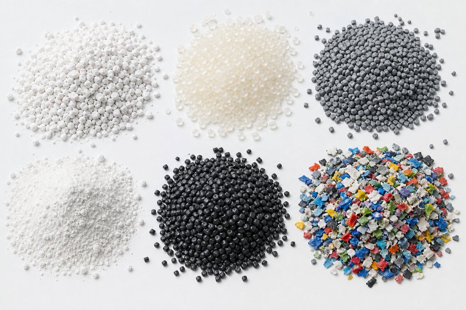
A perfectly tuned compounding extruder running the wrong screw profile for the material in the hopper will still produce bad output. Every polymer family brings its own combination of melt viscosity, thermal stability, filler compatibility, and shear sensitivity to the barrel - and those properties dictate which extruder type, screw element strategy, and barrel zone approach will actually work. Here is the material-to-configuration mapping that turns general extrusion knowledge into application-specific action.
Polyolefins and Engineering Plastics
Polyolefins like polypropylene (PP) and polyethylene (PE) are the bread and butter of twin screw compounding extruder operations. These materials melt cleanly, tolerate relatively high shear, and flow easily once plasticized. The processing challenge is rarely the polymer itself - it is dispersing whatever you are putting into it. Calcium carbonate at 40% loading, talc, glass fibers, flame retardants, UV stabilizers, pigment concentrates: each additive demands that filler agglomerates be broken apart and distributed uniformly through the melt.
Co-rotating extruders dominate here because their self-wiping geometry and aggressive kneading block capability deliver the dispersive mixing intensity these formulations require. Screw profiles typically feature multiple kneading zones with forward and neutral stagger angles, sometimes followed by toothed mixing elements for distributive polishing. Barrel temperatures follow an ascending or flat profile that keeps viscosity low enough for efficient filler wetting.
Engineering plastics - polyamide (PA), polybutylene terephthalate (PBT), polycarbonate (PC) - shift the equation. These resins process at significantly higher temperatures, and many are hygroscopic, meaning moisture causes hydrolytic degradation if not removed. A compounding twin screw extruder running glass-filled PA66, for example, needs gentler kneading sections to avoid fiber breakage, robust devolatilization zones for moisture removal, and precise descending temperature profiles that prevent the melt from overshooting its thermal ceiling in the mixing zones. Screw speed is often moderated compared to polyolefin processing because excessive shear generates enough viscous dissipation to push melt temperatures into the degradation range.
PVC and Heat-Sensitive Polymers
PVC stands apart from nearly every other commodity polymer. It begins degrading - releasing hydrochloric acid and discoloring - at temperatures uncomfortably close to its processing range. High shear accelerates this degradation by converting mechanical energy into localized heat spikes that the barrel cooling system cannot remove quickly enough. This is why PVC processing overwhelmingly relies on counter-rotating conical twin-screw extruders, as industry application data confirms: their low-shear, high-pressure design prevents material breakdown while maintaining the dimensional stability required for rigid pipes, profiles, and sheet.
The screw plastic extruder configuration for PVC looks fundamentally different from a polyolefin setup. Screw speeds are low - often 10 to 60 RPM compared to the hundreds of RPM common in co-rotating compounding. Barrel temperatures are held tightly within a narrow window, sometimes spanning as little as 10-15 degrees across all zones. The conical screw geometry naturally builds pressure toward the die without requiring the aggressive compression elements that would generate destructive shear.
This same logic extends to other heat-sensitive materials. Certain bioplastics, such as PLA and PHA blends, degrade rapidly under excessive shear and prolonged residence time. While these materials may use co-rotating machines at reduced speeds, the screw profile must minimize aggressive kneading in favor of gentler distributive mixing elements - and barrel zones must provide active cooling to counteract viscous dissipation.
Recycled Plastics and Specialty Compounds
Recycling is where the polymer extruder faces its toughest test. Post-consumer and post-industrial feedstocks arrive contaminated with moisture, paper labels, residual food, mixed polymer fractions, and volatile degradation byproducts. The extruder for polymer recycling must handle all of this variability while producing pellets clean and consistent enough for downstream molding or extrusion.
Co-rotating machines dominate recycling applications because their devolatilization capability is unmatched. Multiple vacuum venting zones strip moisture and volatiles from the melt, while robust screw elements tolerate the abrasive contaminants that would rapidly wear less durable components. Melt filtration - typically a screen changer positioned between the extruder discharge and pelletizer - removes solid contaminants that survive the extrusion process. Screw profiles emphasize long melting sections, intensive devolatilization, and extended metering zones for stable output pressure.
Specialty compounds add their own layer of complexity. Thermoplastic elastomers (TPE) require careful balancing of dispersive mixing for phase morphology control without over-shearing the soft-block phase. Masterbatch production - concentrating pigments or additives at high loading levels - demands maximum distributive mixing to achieve streak-free dispersion. Highly filled compounds with mineral loadings exceeding 70% push torque density to its limits and require a plastic twin screw extruder with gearbox capacity well beyond what unfilled resins demand.
The following reference list organizes these material families into a scannable format, mapping each to its recommended configuration:
- Polyolefins (PP, PE) with fillers or additives - Recommended: co-rotating parallel extruder. Screw emphasis: aggressive kneading blocks for filler dispersion. Barrel strategy: ascending or flat temperature profile. Primary challenge: achieving uniform filler distribution at high loading levels without excessive melt temperature rise.
- Engineering plastics (PA, PBT, PC) - Recommended: co-rotating parallel extruder at moderate screw speed. Screw emphasis: gentler kneading sections, robust devolatilization zones. Barrel strategy: descending temperature profile with active cooling in mixing zones. Primary challenge: preventing thermal degradation and fiber breakage while removing moisture.
- Rigid PVC (pipes, profiles, sheet) - Recommended: counter-rotating conical extruder. Screw emphasis: low-shear conveying with gradual compression. Barrel strategy: tight, narrow temperature window across all zones. Primary challenge: staying within PVC's extremely narrow processing window to avoid degradation.
- Heat-sensitive bioplastics (PLA, PHA) - Recommended: co-rotating extruder at reduced speed, or counter-rotating for forming applications. Screw emphasis: distributive mixing elements over aggressive kneading blocks. Barrel strategy: moderate temperatures with active cooling. Primary challenge: balancing adequate melting and mixing against thermal and hydrolytic degradation.
- Recycled plastics (post-consumer PE, PP, PET) - Recommended: co-rotating parallel extruder with multiple vent zones. Screw emphasis: extended melting sections, intensive devolatilization, robust wear-resistant elements. Barrel strategy: profile matched to base resin type with cooling capacity for volatile removal zones. Primary challenge: managing feedstock variability, moisture, and contamination while producing consistent pellet quality.
- TPE (thermoplastic elastomers) - Recommended: co-rotating extruder. Screw emphasis: controlled dispersive mixing for phase morphology without destroying elastomeric domains. Barrel strategy: moderate temperatures to avoid soft-phase degradation. Primary challenge: achieving target hardness and mechanical properties through precise morphology control.
- Masterbatch (pigment and additive concentrates) - Recommended: co-rotating extruder. Screw emphasis: maximum distributive mixing with toothed elements (TME/ZME) for streak-free dispersion. Barrel strategy: temperature matched to carrier resin. Primary challenge: complete pigment or additive dispersion at very high concentrate loadings.
- Highly filled mineral compounds (CaCO3, BaSO4 > 60%) - Recommended: co-rotating extruder with high torque density gearbox. Screw emphasis: staged side feeding of filler downstream of melt zone, intensive kneading. Barrel strategy: ascending profile to reduce melt viscosity for filler incorporation. Primary challenge: extreme torque demand and abrasive wear on screw elements and barrel liners.
Each of these material-configuration pairings represents a starting point, not a final answer. Real-world optimization always involves adjusting screw element sequencing, speed, feed rate, and temperature profile in response to actual output quality - which is why no extruder operates in isolation. The upstream feeding systems, downstream pelletizers, cooling equipment, and die design that surround the extruder all influence whether a theoretically correct configuration translates into consistently good product at the end of the line.
The Complete Twin-Screw Extrusion Line Explained
A perfectly configured screw extruder means little if the feeder starving it fluctuates by 5% or the pelletizer downstream cannot keep pace with throughput. The extruder is the heart of the processing line, but production quality is ultimately determined by every piece of equipment between the raw material hopper and the finished product. Thinking in terms of a complete extruder system - not just the barrel and screws - is what separates lines that produce consistent output from lines that fight bottlenecks shift after shift.
Upstream Feeding Systems
The extrusion process begins before material ever reaches the screws. Feeders set the pace and accuracy of the entire operation, and the type of feeder you choose directly impacts process consistency.
Volumetric feeders deliver material at a constant volume per unit time using a screw or vibratory mechanism. They are simpler and less expensive, but as feeding system specialists point out, the control system has no awareness of how much material is actually on the feeder. If bulk density shifts - due to moisture absorption, varying pellet size, or powder bridging - the mass flow rate drifts without any automatic correction.
Gravimetric (loss-in-weight) feeders incorporate a weighing system that continuously measures material usage and adjusts the feed mechanism to maintain a constant mass flow rate. When multiple ingredients must be dosed into the barrel simultaneously - polymer, filler, stabilizer, pigment - gravimetric feeders maintain recipe accuracy that volumetric systems simply cannot match. The cost premium is real, but for any process where formulation consistency drives product quality, it pays for itself quickly.
Beyond primary feeders, two additional upstream systems play critical roles:
- Side feeders - These are small co-rotating twin-screw augers that push fillers, fibers, or secondary additives into the barrel extruder at a point downstream of the melt zone. Introducing glass fibers or mineral fillers after the polymer has already melted protects them from the high-shear melting zone, reducing fiber breakage and improving dispersion. As described in published extrusion research, side stuffing also reduces residence time exposure for heat-sensitive materials by avoiding the initial high-energy melting section entirely.
- Liquid injection systems - Piston pumps or gear pumps introduce plasticizers, coupling agents, reactive additives, or liquid colorants directly into the melt stream at designated barrel ports. Precise volumetric or mass-flow-controlled injection ensures uniform distribution without flooding the screw channels or destabilizing pressure profiles.
Downstream Equipment and Finishing
Everything that happens after material exits the die determines the final form, dimensions, and quality of the product. Imagine the extruder delivering a perfectly homogenized melt - if the downstream chain cannot cool, cut, and collect it properly, all that upstream precision goes to waste.
The downstream chain varies by application, but the core sequence of a complete extrusion line from raw material to finished product follows a consistent logic:
- Raw material storage and handling - Silos, dryers, and conveying systems deliver feedstock to the loss-in-weight or volumetric feeders positioned above the extruder throat.
- Primary feeding - Gravimetric or volumetric feeders meter the base polymer and primary additives into the screw extruder at controlled rates.
- Side feeding and liquid injection - Secondary ingredients enter the barrel downstream through side stuffers or injection ports at designated barrel zones.
- Extrusion and processing - The twin-screw extruder melts, mixes, devolatilizes, and pressurizes the formulation through its modular screw and barrel assembly.
- Die head - The pressurized melt exits through a die that shapes it into the required form. Common die types include strand dies (producing spaghetti-like strands for pelletizing), underwater pelletizing dies (with a cutting face submerged in water), sheet and film dies (flat slot geometry), and profile dies (custom cross-sections for pipes, window frames, or structural shapes).
- Cooling - Strands pass through a water bath or are air-cooled on a conveyor belt. Underwater pelletizing systems cool and cut simultaneously. Sheet exits onto temperature-controlled chill rolls. Profile extrusions pass through vacuum sizing tanks followed by spray cooling.
- Pelletizing or sizing - Strand pelletizers pull cooled strands through rotating blades that chop them into uniform pellets. Underwater pelletizers cut molten strands at the die face, producing spherical pellets that cool instantly in the water stream. Hot-face pelletizers operate similarly but without full water immersion.
- Drying and classification - Pellets are dried using centrifugal dryers or fluidized beds, then screened or classified to remove fines, oversized pieces, or agglomerates before packaging or further processing.
- Packaging or secondary operations - Finished pellets are conveyed to bagging stations, bulk containers, or directly to downstream molding or extrusion equipment. Profiles and sheets may undergo printing, punching, or assembly operations.
Why System Integration Determines Line Performance
Here is a scenario that plays out in facilities everywhere: a production team upgrades to a higher-throughput barrel extruder but keeps the existing pelletizer. The extruder can now push 800 kg/h, but the pelletizer maxes out at 600 kg/h. The result is not a 600 kg/h line - it is an unstable one. Back-pressure builds at the die, melt temperature rises, strand breaks increase, and product quality deteriorates. The bottleneck is not the extruder. It never was.
The same principle applies in reverse. A gravimetric feeder rated for laboratory-scale throughput cannot supply a production-scale screw extruder with the consistent mass flow it needs. Feed rate oscillations translate directly into torque swings, pressure fluctuations at the die, and dimensional variation in the final product.
Screw extruder granulator setups illustrate this interdependence perfectly. The extruder's throughput capacity, the die's hole count and geometry, the pelletizer's cutting speed, and the cooling system's heat removal rate must all be designed as a matched extruder system. Changing any single component without evaluating its impact on the rest of the chain risks creating a new bottleneck - or exposing a hidden one that was previously masked by lower throughput.
Extruder performance is only as good as the weakest link in the line. A mismatch between feeder accuracy, extruder throughput, and pelletizer capacity does not reduce output proportionally - it destabilizes the entire process.
Even the best-integrated line, however, will encounter problems during production. Filler agglomerates that survive the mixing zone, thermal degradation that appears as black specks, surging output that defies parameter adjustments - these are the operational realities that every extrusion team faces. Diagnosing these issues quickly, before they cascade into scrap and downtime, requires a structured troubleshooting approach built on understanding root causes rather than chasing symptoms.
Troubleshooting Common Twin-Screw Extrusion Problems
You have the right extruder configuration, a well-designed screw profile, an integrated downstream line - and yet something goes wrong. Maybe the pellets show color streaks. Maybe output surges erratically every few minutes. Maybe there are black specks in the extrudate that were not there last week. Every production team encounters these situations, and the difference between an hour of downtime and a full shift of scrap often comes down to how quickly you can connect a visible symptom to its root cause.
What follows is a structured troubleshooting reference organized by problem category. Bookmark this section - it is designed to be the first place you look when something on the line stops behaving the way it should.
Mixing and Dispersion Problems
Poor mixing is one of the most common quality complaints in twin-screw compounding, and it shows up in ways that are easy to spot but harder to diagnose. Undispersed filler agglomerates appear as visible specks or gritty texture in pellets and molded parts. Color streaks indicate that pigment concentrates are not being distributed uniformly through the melt. Inconsistent melt viscosity - visible as strand diameter variation at the die - suggests the melt itself is not homogeneous.
The instinct is to crank up screw speed, but that is a blunt instrument. Before adjusting any parameter, consider the three most likely causes:
- Insufficient kneading block intensity - If the screw profile lacks enough kneading elements, or if the stagger angles are too gentle (all forward-pitch kneading with no neutral or reverse blocks), the melt simply does not experience enough shear stress to break down agglomerates. This is a screw design issue, not an operating parameter issue. Increasing the number of kneading blocks in the mixing zone - or swapping forward-stagger blocks for neutral 90-degree blocks - directly increases dispersive mixing intensity.
- Incorrect screw speed-to-feed ratio - If the fill ratio is too high (overfeeding relative to screw speed), material passes through the kneading zone too quickly for adequate dispersion. Reducing the feed rate while maintaining screw speed gives the material more time under shear. Conversely, if the fill ratio is extremely low, the kneading blocks may not have enough material to work against, producing inconsistent mixing.
- Worn screw elements - This is the cause that operators most often overlook. As a plastic extruder screw wears, the self-wiping clearance between intermeshing screw flights increases. That gap, which may start at fractions of a millimeter, allows material to leak past the kneading zone without experiencing the full shear field. The result is a gradual, progressive decline in mixing quality that gets worse month after month. Industry troubleshooting guidelines recommend measuring screw diameter at multiple points during routine maintenance - once wear exceeds the manufacturer's specified limit, mixing efficiency drops significantly and element replacement becomes necessary.
Material Degradation and Thermal Issues
Degradation problems are insidious because they often develop slowly before becoming obvious. Discoloration - yellowing in natural resins, darkening in colored compounds - indicates thermal or thermal-oxidative damage to the polymer chains. Black specks are typically carbonized material that has stagnated in a dead zone within the barrel, burned onto a surface, and then broken free into the melt stream. Reduced mechanical properties in finished parts, especially impact strength and elongation at break, point to molecular weight reduction caused by chain scission during processing.
Research on polypropylene degradation during twin-screw extrusion from Paderborn University confirms that high rotational speeds, low throughputs, and high melt temperatures all increase material degradation - independent of machine size. The study demonstrated that these three parameters drive chain scission through combined thermal, thermal-oxidative, and mechanical degradation mechanisms, with the effect of higher shear and temperature outweighing the material-protective benefit of shorter residence time.
When degradation symptoms appear on a previously stable process, work through these probable causes:
- Excessive residence time - A low feed rate relative to barrel volume means material spends too long at elevated temperatures. Increasing throughput or reducing the number of restrictive elements in the screw profile shortens residence time and reduces thermal exposure.
- Barrel temperature overshoot - Faulty heaters, malfunctioning thermocouples, or incorrect PID controller tuning can push zone temperatures well above setpoints. Verify actual barrel temperature with a calibrated handheld thermometer, inspect heater bands for damage, and flush cooling lines to remove mineral deposits that restrict cooling water flow.
- Dead zones in the screw configuration - Improperly placed reverse elements, damaged kneading blocks, or worn barrel liners can create pockets where material stagnates, overheats, and carbonizes. These dead zones are the primary source of black specks. Pulling the screws for inspection usually reveals the telltale burned residue at the problem location.
- Insufficient cooling capacity - In high-shear zones, viscous dissipation generates significant heat inside the melt. If the barrel cooling system cannot remove that energy fast enough - due to low water flow rates, fouled cooling channels, or undersized heat exchangers - actual melt temperature climbs above the barrel setpoint and degradation accelerates.
Off-gassing during extrusion is another degradation indicator. Volatile byproducts released by overheated polymer create bubbles in the melt, surface voids in pellets, and unpleasant odors at the die. In many cases, improving devolatilization alone will not solve the problem - you need to address the upstream cause of degradation rather than just venting its symptoms.
Output Instability and Mechanical Wear
Surging - a rhythmic fluctuation in output rate that appears as pressure oscillation at the die head - is one of the most frustrating problems in twin-screw extrusion. The extrudate alternately thickens and thins, pellet dimensions vary, and line operators chase the problem from one end of the machine to the other without finding a clear cause.
Practical troubleshooting experience identifies four root causes behind most surging events: inconsistent feeding (feeder speed too high or material bridging in the hopper), screw and barrel wear (reduced conveying efficiency), contamination by foreign objects creating intermittent blockages, and faulty temperature control leaving zones underheated so material passes through partially unmelted.
Die drool - the slow buildup of degraded material at the die lip - is another output quality issue with mechanical roots. As material exits the die, low-molecular-weight fractions and degradation byproducts accumulate on the die face, eventually breaking free and contaminating the extrudate. The causes overlap with degradation: excessive melt temperature, polymer breakdown, and inadequate die design or surface finish.
Torque spikes - sudden jumps in motor load that may trigger overload alarms - often signal that something has changed mechanically. A foreign object entering the barrel, a cold slug of unmelted polymer hitting the kneading zone, or severely worn twin screws that can no longer convey material efficiently can all produce torque events. Repeated torque spikes without an obvious external cause usually point to worn screw elements or barrel liners that have increased clearance to the point where the screws struggle to build and maintain pressure.
When the plastic extrusion screw and barrel wear progresses far enough, the effects compound. Increased clearance between flights reduces pumping efficiency, which lowers throughput at any given screw speed. The machine draws more power trying to maintain output, melt temperature climbs from the extra energy input, and product quality degrades on multiple fronts simultaneously. This is why regular inspection and timely replacement of twin screw and barrel components is the single most effective preventive maintenance strategy available to production teams.
Quick-Reference Troubleshooting Table
The table below consolidates the most common twin-screw extrusion problems into a scannable diagnostic reference. For each issue, it lists the most probable causes and the corrective actions to try first.
| Problem | Probable Causes | Corrective Actions |
|---|---|---|
| Undispersed filler agglomerates or color streaks | Insufficient kneading block intensity in screw profile; screw speed-to-feed ratio too low; worn screw elements with increased self-wiping clearance | Add or intensify kneading blocks (switch to neutral or reverse stagger); reduce feed rate or increase screw speed to lower fill ratio; inspect and replace worn screw elements |
| Discoloration or yellowing of extrudate | Barrel temperature overshoot; excessive residence time at elevated temperature; thermal-oxidative degradation from oxygen exposure at low fill levels | Verify thermocouple accuracy and PID settings; increase throughput to reduce residence time; check barrel cooling system for flow restrictions; increase fill ratio to limit oxygen contact |
| Black specks in pellets or extrudate | Carbonized material in dead zones from stagnant flow; degraded buildup on barrel wall or screw root; worn elements creating pockets where material hangs up | Pull screws and inspect for carbon deposits; clean barrel thoroughly; eliminate dead zones by adjusting screw element sequencing; replace damaged or worn elements |
| Reduced mechanical properties (impact, elongation) | Molecular weight reduction from excessive shear or thermal exposure; high screw speed at low throughput maximizing chain scission | Lower screw speed or increase throughput to reduce specific energy input; use a less aggressive screw profile; reduce barrel temperatures in mixing zones |
| Surging or fluctuating output | Inconsistent feeder delivery; material bridging in hopper; worn screw or barrel reducing conveying efficiency; partially unmelted material from faulty heater zones | Recalibrate feeder; install hopper agitator; inspect and replace worn twin screws and barrel liners; verify all heater bands and thermocouples are functional |
| Die drool and lip buildup | Low-molecular-weight degradation products accumulating at die exit; excessive melt temperature; poor die surface finish | Reduce melt temperature by lowering barrel setpoints or screw speed; polish die exit surfaces; clean die face regularly during production; review screw profile for excessive shear zones |
| Torque spikes or overload alarms | Foreign object in barrel; cold startup with unmelted polymer slug; severely worn screw elements unable to convey efficiently; overfeeding beyond machine capacity | Shut down immediately and inspect barrel for foreign material; ensure proper preheat before starting screws; replace worn elements; reduce feed rate to match extruder capacity |
| Bubbles or voids in extrudate | Moisture in feedstock; volatile degradation byproducts from overheating; insufficient devolatilization vacuum | Pre-dry all hygroscopic materials to target moisture level; reduce barrel temperatures to eliminate degradation; verify vacuum pump performance and vent port clearance |
| Excessive screw and barrel wear | Processing abrasive fillers (glass fiber, mineral) without wear-resistant metallurgy; screw misalignment; operating above recommended torque or speed limits | Upgrade to nitrided or bimetallic screw elements and barrel liners; check screw alignment and shaft concentricity; operate within 80% of maximum torque rating |
A pattern runs through nearly every row in this table: worn twin screws and barrel components appear as either a direct cause or a contributing factor in the majority of common extrusion problems. Mixing quality degrades as clearances open up. Output surges as pumping efficiency drops. Degradation accelerates as dead zones form around damaged elements. The implication is clear - proactive inspection and replacement of plastic extruder screw elements and barrel liners before they reach critical wear limits prevents most of these problems from ever reaching the production floor.
Troubleshooting fixes the immediate issue. But the longer-term question - choosing the right equipment and maintaining access to quality replacement components over the life of the machine - is what determines whether these problems remain rare events or recurring disruptions. That decision starts with evaluating both the extruder manufacturer and the screw barrel supply partner who will support the line for years after installation.
Choosing the Right Twin-Screw Extruder and Screw Barrel Partner
Diagnosing a surging output or replacing a worn kneading block solves today's problem. The question that shapes the next five to ten years of production quality is different: which twin-screw extruder machine do you invest in, and who supplies the screw and barrel components that keep it running at specification long after installation day?
These two decisions - the original equipment purchase and the aftermarket component partnership - are equally consequential. A machine from a reputable twin-screw extruder manufacturer will deliver strong initial performance, but every set of screws and barrel liners has a finite service life. Abrasive fillers, high-torque operations, and aggressive kneading profiles accelerate wear. When clearances open up, mixing quality drops, output destabilizes, and degradation issues start appearing - as the troubleshooting section above illustrates. The facility that has a reliable, fast source for precision replacement components recovers in hours. The one that does not loses days waiting for parts while scrap accumulates.
Key Factors When Evaluating Twin Screw Extruder Manufacturers
Shopping for a twin screw extruder for sale can feel overwhelming. Brochures from every twin-screw extruder manufacturer highlight impressive throughput numbers and polished machine photos, but the specifications that actually determine long-term value are often buried or unstated. When comparing options, work through the following evaluation criteria systematically - they separate machines that perform reliably for years from machines that look good on paper but underdeliver in production.
- Application-specific experience - Has the manufacturer built and commissioned lines for your specific material and application? A company with deep experience in PVC profile extrusion may not be the right fit for reactive compounding, and vice versa. Ask for reference installations processing similar formulations at comparable throughput.
- Available screw diameter range - The diameter range a manufacturer offers signals the breadth of their engineering capability. Twin screw extruder manufacturers who cover everything from lab-scale (16-27 mm) through pilot (35-50 mm) to full production (62-135 mm+) typically maintain deeper process knowledge across applications and scales.
- Torque density class - As discussed in the specifications section, specific torque density (Nm/cm3) defines the mechanical ceiling for demanding materials. Compare gearbox ratings directly - not just maximum torque, but the torque density normalized to screw cross-section. High-performance machines reaching 13-18 Nm/cm3 handle heavily filled compounds and high-viscosity melts that would stall lower-capacity drives.
- Barrel metallurgy options - Different materials attack barrel liners in different ways. Glass-fiber-filled compounds demand wear-resistant metallurgy; corrosive polymers like fluoropolymers or halogenated flame retardants require corrosion-resistant alloys. Verify that the manufacturer offers multiple barrel liner materials - nitrided steel, bimetallic liners, and specialty alloys - matched to your processing conditions.
- Automation and control system sophistication - Modern extrusion lines benefit from integrated PLC or DCS control with real-time monitoring of torque, melt pressure, melt temperature, and specific energy. Some twin screw extruder manufacturers offer proprietary control platforms with data logging and recipe management; others integrate with third-party systems. Evaluate whether the control architecture supports the level of process visibility and reproducibility your operation requires.
- Spare parts availability and lead time - This is the factor most buyers underweight during the initial purchase decision and most regret later. Ask explicitly: what is the lead time for replacement screw elements, barrel sections, and gearbox components? Are standard wear parts stocked, or manufactured to order? A twin screw extruder price that looks attractive upfront becomes far less appealing if every replacement barrel section takes twelve weeks to arrive.
- Aftermarket screw and barrel support - Original equipment manufacturers are not the only source for replacement components, and in many cases they are not the fastest or most cost-effective option. Independent screw and barrel specialists often deliver precision components with shorter lead times and competitive pricing - particularly for standard screw element geometries and barrel liner configurations used across multiple machine brands.
That last point deserves emphasis. The twin screw extruder price you pay at purchase covers the machine, installation, and commissioning. But over the machine's operational lifetime - typically ten to twenty years or more - the cumulative cost of screw elements, barrel liners, and wear components can rival or exceed the original capital investment. Worn components are the primary source of quality degradation over time: mixing efficiency drops, output stability erodes, and degradation problems emerge. Having a dependable aftermarket supply chain for these critical parts is not optional - it is a core operational requirement.
Where to Find Reliable Screw Barrel Support for Your Extrusion Line
Whether your facility runs PVC pipe lines, engineering plastic compounding systems, sheet extrusion setups, pelletizing operations, or post-consumer recycling lines, the need is the same: precision-manufactured screw and barrel replacements that maintain the tight tolerances your process depends on, delivered fast enough to minimize production downtime.
This is exactly the gap that specialized component suppliers fill. Rather than waiting weeks for OEM parts or accepting generic components with uncertain dimensional accuracy, production teams benefit from working with suppliers who focus exclusively on extruder screw and barrel engineering. NANHAIYA's plastic extruder machine and screw barrel support is one such resource - connecting extrusion manufacturers, recycling plants, and technical teams with components engineered for pipe, profile, sheet, pelletizing, and general plastic processing lines. Their focus on screw barrel solutions across all major extrusion applications means that whether you need replacement kneading blocks for a co-rotating compounder or barrel liners for a conical PVC line, the components are designed to match your machine's specifications and processing demands.
When evaluating any screw barrel supplier - NANHAIYA or otherwise - apply the same rigor you would to the extruder purchase itself:
- Do they offer components for your specific machine type and screw diameter?
- Can they provide metallurgy options matched to your material (nitrided, bimetallic, specialty alloys)?
- What are their dimensional tolerances, and do they document them?
- How quickly can they deliver standard and custom components?
- Do they support both co-rotating and counter-rotating configurations?
A supplier who can answer these questions with specifics - not generalities - is a supplier worth building a long-term relationship with. The goal is simple: keep your twin-screw extruder running at original-equipment performance levels throughout its entire service life, not just during the first year after installation.
The right twin-screw extruder machine, paired with quality screw and barrel components maintained on a proactive replacement schedule, is the foundation of efficient, high-quality plastics processing - not just on day one, but for every production year that follows.
Frequently Asked Questions About Twin-Screw Extruder Machines
1. What is the difference between a co-rotating and counter-rotating twin-screw extruder?
A co-rotating twin-screw extruder has both screws turning in the same direction, producing high-shear dispersive mixing and a fully self-wiping action that prevents material stagnation. It excels in compounding, masterbatch, reactive extrusion, and recycling. A counter-rotating twin-screw extruder turns the screws in opposite directions, generating lower shear through a calendering effect at the intermesh zone. This gentler processing makes it ideal for heat-sensitive materials like PVC, where thermal degradation is a constant risk. Counter-rotating designs come in parallel and conical geometries, with conical versions dominating PVC pipe and profile extrusion due to their natural pressure-building taper.
2. How do you choose the right screw elements for a twin-screw extruder?
Screw element selection depends on the processing goal at each barrel zone. Forward-pitch conveying elements dominate the feed and metering zones for material transport and pressure buildup. Kneading blocks handle the primary mixing work - wider discs with neutral or reverse stagger angles deliver aggressive dispersive mixing for breaking filler agglomerates, while narrow forward-stagger blocks provide gentler distributive blending. Toothed mixing elements like TME and ZME split and recombine flow for uniform distribution without excessive shear. Reverse-pitch elements create pressure seals upstream of devolatilization vents. The key is sequencing these elements along the shaft so each barrel zone accomplishes its specific function - feeding, melting, mixing, devolatilizing, and metering - without creating dead zones or excessive thermal exposure. Suppliers like NANHAIYA (nhyscrews.com) offer precision-manufactured elements engineered for specific extrusion applications including pipe, profile, sheet, and pelletizing lines.
3. What L/D ratio should I choose for my twin-screw extruder?
The ideal L/D ratio depends on process complexity. Lower ratios around 20:1 to 28:1 suit simpler compounding tasks and thermally sensitive polymers like PVC, where minimizing residence time prevents degradation. Moderate ratios of 32:1 to 36:1 cover general-purpose compounding, masterbatch production, and moderate devolatilization needs. Higher ratios of 40:1 and above are necessary for multi-stage processes such as reactive extrusion, heavy devolatilization, high-filler-loading compounding, and applications requiring multiple side feeders. Each barrel section adds independently controlled temperature zones and potential locations for vents or injection ports, so a higher L/D ratio also means greater process configuration flexibility - but at the cost of increased power demand and potential shaft deflection.
4. Why does my twin-screw extruder produce inconsistent output or surging?
Surging typically stems from four root causes: inconsistent feeding from a poorly calibrated feeder or material bridging in the hopper, worn screw elements and barrel liners that reduce conveying efficiency, contamination creating intermittent blockages in the barrel or die, and faulty temperature control leaving certain zones underheated so material passes through partially unmelted. Start troubleshooting at the feeder - verify consistent mass flow using a gravimetric system if possible. Next, inspect screw elements for wear by measuring flight diameters at multiple points. Check all heater bands and thermocouples for proper function. If wear is the culprit, replacing worn screw and barrel components restores pumping efficiency and stabilizes output pressure at the die.
5. What materials are best processed on a twin-screw extruder versus a single-screw extruder?
Twin-screw extruders outperform single-screw machines whenever intensive mixing, filler dispersion, devolatilization, or feedstock variability is involved. Filled polyolefin compounds, engineering plastic blends, masterbatch concentrates, thermoplastic elastomers, recycled plastics with contaminants, and reactive extrusion chemistries all benefit from the superior mixing intensity and self-wiping action of twin-screw designs. Single-screw extruders remain effective for simpler tasks like unfilled profile extrusion, blown film, and pipe extrusion with pre-compounded materials where the polymer just needs to be melted and shaped without intensive mixing. If your process requires dispersing additives above roughly 10-15% loading, blending immiscible polymers, or removing volatiles from the melt, a twin-screw extruder is nearly always the better choice.
Written by
Nanhaiya Technical Team
Zhoushan Nanhaiya Plastic Machinery Co., Ltd.
The Nanhaiya technical team supports screw and barrel manufacturing projects through application review, technical communication, custom manufacturing coordination, and production and quality control.
Discuss Your Application
Related Articles
More insights on screw barrel technology and plastics processing.

What Nobody Tells You About Screw Barrel For Plastic Machine Design
Oct 10, 2026
Learn how screw barrel for plastic machine design affects melt quality, throughput, and wear life. Covers geometry, resin matching, troubleshooting, and sourcing.
Read Article
Single Screw Extruder for Sheet: Stop Guessing, Start Specifying
Oct 9, 2026
Learn how to specify a single screw extruder for sheet production. Covers screw geometry, resin-specific processing, troubleshooting, and maintenance best practices.
Read Article
PE Pipe Extruder Machine: What Datasheets Won't Tell You
Oct 9, 2026
Learn how a PE pipe extruder machine works, key specs explained, material grade selection, maintenance tips, and buyer guidance beyond the datasheet.
Read ArticleLooking for something else?
Search by material, symptom or product and jump straight to the relevant page.
These are navigation suggestions based on keyword matching — not a quotation, not a delivery commitment, and not a substitute for engineering review. Final specification is confirmed by our engineers against your drawings and processed material.
Need help with screw barrel selection?
Share your machine model, processed material and application. Our team can help with pricing and technical support.