

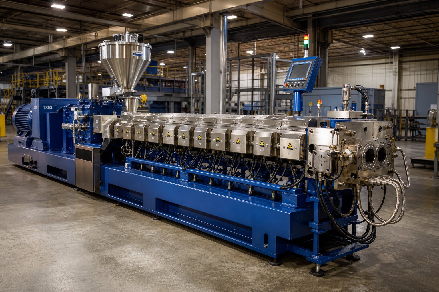
What Is a Twin-Screw Extruder and How Does It Work
Imagine two precisely engineered screws spinning side by side inside a heated barrel, pulling in raw plastic pellets at one end and pushing out a perfectly mixed, molten stream at the other. That, in its simplest form, is what a twin-screw extruder does — and it is the single most versatile processing machine in the polymer industry today.
Whether you are exploring extruders meaning for the first time or evaluating a machine upgrade for a production line, this guide walks you through everything from foundational definitions to advanced screw design strategy. Beginners will leave with a solid understanding of how the technology works, while seasoned engineers will find actionable guidance on element arrangement, specification interpretation, and process optimization.
Definition and Core Function of a Twin-Screw Extruder
A twin-screw extruder is a processing machine that uses two intermeshing or non-intermeshing screws, rotating inside a closely fitted barrel, to convey, melt, mix, and shape polymers and other materials through precisely controlled combinations of shear, heat, and pressure.
The two screws are the engine of the entire process. As they rotate — either in the same direction (co-rotating) or in opposite directions (counter-rotating) — they grip incoming material, drag it forward, and subject it to intense mechanical and thermal energy. Raw feedstock enters the barrel as a solid powder, pellet, or flake. Within seconds, it is compressed, melted, thoroughly blended with additives or fillers, degassed, and pressurized before exiting through a shaping die.
What makes a twin screw extruder fundamentally different from a single-screw machine is the interaction between those two screws. In intermeshing designs, the flight of one screw fits into the channel of the other, creating a self-wiping action that prevents material from stagnating on the barrel wall. This geometry delivers tight residence time control, consistent melt quality, and far superior mixing — capabilities that a single screw simply cannot match.
Why Twin Screw Extruders Matter in Modern Processing
You will find twinscrew technology at the core of industries you might not immediately associate with plastic processing. Plastics compounding is the most obvious application — color masterbatch, glass-fiber-reinforced compounds, and flame-retardant formulations all depend on the machine's ability to disperse additives uniformly into a polymer matrix. Yet the same operating principles power snack food texturization lines, pharmaceutical hot-melt extrusion systems, and specialty chemical reactors.
Three characteristics explain why twin screw extruders have become the dominant processing platform across these diverse fields:
- Versatility — A single machine can process low-viscosity resins, highly filled compounds, reactive chemistries, and moisture-laden recyclates simply by reconfiguring its modular screw elements.
- Modularity — Barrel segments, screw elements, and downstream dies can be swapped to match virtually any formulation or product geometry, reducing the need for dedicated equipment.
- Superior mixing — The intermeshing screw geometry provides both distributive mixing (spreading additives evenly) and dispersive mixing (breaking down agglomerates), often in a single pass.
It is also important to see the twin screw extruder not as a standalone device but as the centerpiece of a complete process ecosystem. Upstream, gravimetric and volumetric feeders meter raw materials into the barrel at precise rates. Downstream, strand pelletizers, underwater pelletizers, and cooling conveyors convert the extrudate into finished pellets ready for shipment or further molding. Every link in this chain affects final product quality — a concept we will revisit throughout the article.
The real depth, however, lies in the details: how individual screw elements shape the melt, how specification numbers translate into processing capability, and how parameter adjustments at the control panel ripple through the entire extrusion process. That journey begins with the step-by-step path material follows from the moment it enters the feed throat.
How the Twin-Screw Extrusion Process Works Step by Step
A pellet drops into the feed throat. Less than a minute later, a uniform, bubble-free melt strand emerges from the die — compounded, degassed, and ready for pelletizing. What happens in between is not one continuous event but a carefully staged sequence, and understanding each stage is the key to understanding twin screw extrusion itself.
From Feed Throat to Die Exit — The Processing Stages
Think of the barrel as a series of task-specific rooms, each designed to do one job extremely well. The material passes through these rooms in a fixed order, and the screw geometry changes from zone to zone to accomplish each task. Here is the complete twin screw extrusion process laid out sequentially:
- Solids conveying zone — Coarse-pitch screw flights grip incoming pellets, powders, or flakes and push them forward with minimal compression. The goal here is efficient transport, not melting. The channel is only partially filled in starve-fed operation, which prevents surging and gives operators precise control over throughput.
- Melting and plastication zone — As material advances into heated barrel sections, the screw pitch gradually tightens. A combination of barrel heat and viscous dissipation — the friction generated by shear between the screws, barrel wall, and polymer mass — converts solid feedstock into a molten state. Getting this balance right matters enormously: incomplete melting sends unmelted particles into the mixing zone, while excessive early heating triggers degradation.
- Mixing and kneading zone — This is the heart of the screw extrusion process. Kneading blocks and specialized mixing elements replace simple conveying flights, splitting, folding, and recombining the melt to distribute additives and break apart agglomerates. The stagger angle and disc width of the kneading elements determine whether the mixing is primarily distributive (spreading ingredients evenly) or dispersive (shattering particle clusters).
- Devolatilization and venting zone — Screw geometry shifts again to reduce local pressure and create a partially filled channel. Moisture, trapped air, residual solvents, and reaction by-products escape through vent ports in the barrel. A melt seal formed by upstream elements prevents molten polymer from flooding the opening.
- Melt conveying zone — After venting, conveying elements re-establish a stable, fully filled channel to homogenize the melt and prepare it for final pressurization.
- Pressurization zone — Tighter-pitch elements compress the melt and build the stable, consistent pressure needed to push it through the die at a uniform flow rate. Any fluctuation here shows up immediately as dimensional inconsistency or pellet weight variation downstream.
Each zone's performance depends on the one before it — a concept that makes the entire extruder system function as an integrated chain rather than a collection of independent parts.
Devolatilization and Venting as a Distinct Capability
Venting deserves special attention because it is one of the capabilities that separates twin-screw technology from simpler extrusion platforms. Many polymers absorb moisture from ambient air. Recycled plastics carry residual contaminants. Reactive extrusion generates gaseous by-products. If these volatiles remain trapped in the melt, they cause bubbles, porosity, surface defects, odor, and even hydrolytic degradation of the polymer chain.
How does the machine actually remove them? The screw design creates a deliberate drop in pressure by transitioning from tight-pitch, fully filled elements to wider-pitch, partially filled elements just upstream of a barrel vent port. This pressure reduction, combined with the high melt temperature, causes dissolved volatiles to flash out of the polymer and escape through the opening. Two venting methods are common:
- Atmospheric venting — The vent port is open to ambient pressure, allowing steam and light volatiles to escape naturally. Suitable for moderate moisture levels.
- Vacuum venting — A vacuum pump draws a negative pressure at the vent port, dramatically increasing the driving force for volatile removal. Essential for hygroscopic engineering resins, heavily contaminated recyclates, and processes where residual volatile levels must meet strict specifications.
Effective venting also requires a robust melt seal — typically created by reverse-conveying elements or high-stagger kneading blocks positioned upstream of the vent. Without this seal, molten polymer can flow backward into the vent opening, a defect known as vent flow, which disrupts degassing and creates maintenance headaches.
Upstream and Downstream Equipment in Context
The extruder itself is only the middle act of a larger production story. Upstream, the feeding system sets the stage for everything that follows. Gravimetric feeders weigh material in real time and adjust feed rates to maintain precise formulation ratios — critical when blending a base resin with 40% mineral filler and trace-level stabilizers. Volumetric feeders offer simpler, lower-cost metering for less demanding recipes. Side feeders introduce shear-sensitive ingredients like glass fiber or heat-sensitive additives further down the barrel, after the polymer has already melted.
Downstream, the molten extrudate must be converted into a usable form. Strand pelletizers pull continuous melt strands through a water bath, cool them, and chop them into cylindrical pellets — a straightforward, proven approach. Underwater pelletizers cut the melt directly at the die face, producing spherical pellets ideal for high-throughput compounding lines. Cooling conveyors and classifying screens then bring pellets to storage temperature and sort out any off-spec material.
Viewing the entire line as a single, coordinated extruder system — rather than focusing on the barrel in isolation — is what separates a stable, high-quality operation from one that constantly chases downstream defects back to upstream causes. And yet, even the best feeding strategy and pelletizing setup cannot compensate for a mismatched screw configuration, which is precisely why the choice between co-rotating and counter-rotating designs carries so much weight.
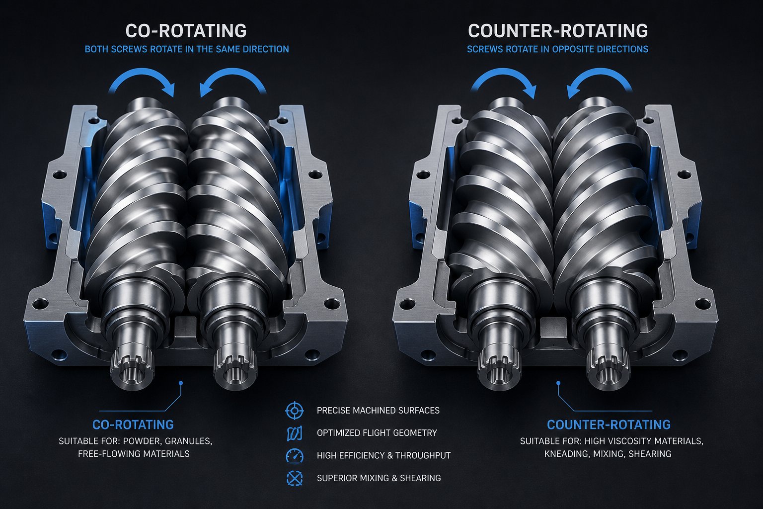
Co-Rotating vs Counter-Rotating Twin-Screw Configurations Explained
Screw configuration is not a minor specification detail — it is the single design choice that determines what your machine can and cannot do. Two screws can rotate in the same direction, in opposite directions, mesh tightly together, or barely interact at all. Each combination creates a fundamentally different flow field, shear profile, and mixing mechanism inside the barrel. Choosing incorrectly means fighting the machine on every production run. Choosing wisely means the process practically runs itself.
So what actually separates a co rotating twin screw extruder from a counter-rotating one, and when does an intermeshing geometry outperform a non-intermeshing design? Let's break each configuration down.
Co-Rotating Intermeshing Twin-Screw Extruders
In a co-rotating design, both screws turn in the same direction — typically with a fully intermeshing, self-wiping geometry. Imagine two gears rotating together: the flight of one screw sweeps through the channel of the other, continuously scraping the barrel wall and the opposing screw surface. This self-wiping action is the defining feature of the configuration, and it produces several critical processing advantages.
First, dead zones virtually disappear. Because neither the barrel wall nor the screw channels ever accumulate stagnant material, the residence time distribution stays remarkably narrow. Every particle of polymer spends roughly the same amount of time inside the barrel, which is essential when processing heat-sensitive materials or running reactive chemistries where even a few extra seconds at temperature can cause degradation or uncontrolled side reactions.
Second, the co-rotating intermeshing geometry generates intense and highly tunable mixing. Material follows a figure-eight ("∞"-shaped) flow path as it transfers from one screw to the other at the intermeshing zone. This continuous handoff, combined with the high shear fields that develop both between the screws and between each screw flight and the barrel wall, delivers excellent distributive and dispersive mixing simultaneously. Engineers can further refine the mixing intensity by selecting different kneading block stagger angles and element sequences — a level of configurability that other designs simply do not offer.
These characteristics explain why the co rotating twin screw extruder dominates the most demanding applications in polymer processing. Compounding with inorganic fillers, carbon nanotubes, and cellulose nanofibers all require aggressive agglomerate breakup without excessive polymer degradation — a balance the co-rotating platform handles well. Reactive extrusion processes, where monomers polymerize or graft inside the barrel, depend on the narrow residence time distribution and precise energy input that this configuration provides. Pharmaceutical hot-melt extrusion, which must meet strict content uniformity standards, relies on the same predictable mixing behavior.
The parallel twin screw extruder — where both screws share a constant diameter from feed end to discharge — is the most common embodiment of this co-rotating, intermeshing concept. Its modular barrel and screw design allows processors to swap individual elements without replacing the entire shaft, making it the preferred workhorse for compounding operations that frequently change formulations.
Counter-Rotating Intermeshing and Non-Intermeshing Designs
Flip the rotation direction and the flow physics change dramatically. In a counter-rotating configuration, the two screws turn in opposite directions. At the intermeshing zone, material is drawn inward between the screws and compressed — a mechanism that resembles two calendar rolls squeezing a sheet of material between them. This calendering effect produces compressive and elongational deformation rather than the intense shear stress characteristic of co-rotating machines.
Why does that matter? Some materials simply cannot tolerate high shear. Rigid PVC, for example, has a narrow window between its processing temperature and its thermal decomposition temperature. The high shear fields inside a co-rotating extruder can push PVC past that threshold, causing discoloration, degradation, and gas evolution. A counter-rotating design keeps shear stress low, holds melt temperature down through low-speed, high-fill operation, and uses the gentle calendering action to achieve adequate dispersion of stabilizers and lubricants without destroying the polymer.
The conical twin screw extruder is a specialized variant of the counter-rotating concept. Its screws taper from a large diameter at the feed end to a smaller diameter at the discharge end, creating a natural compression ratio along the barrel length. This tapered geometry offers two practical benefits: it allows a larger feed opening to accept bulky powders while generating high discharge pressures in a compact footprint. Conical designs are the standard choice for PVC pipe, profile, and sheet extrusion lines — applications where forming pressure matters more than mixing intensity.
Non-intermeshing twin-screw extruders occupy a different niche entirely. Here, the distance between the screw axes equals or exceeds the sum of their outer radii, so the screws rotate side by side without direct mechanical engagement. Material exchange between the two channels occurs through the open gap rather than through forced displacement. The result is a gentler processing environment with lower shear and less self-cleaning capability. Non-intermeshing designs find use in applications that require controlled, low-intensity mixing — certain devolatilization processes, specialty chemical reactions, and situations where preserving molecular weight is more important than achieving microscopic dispersion.
Choosing the Right Configuration for Your Application
With three distinct geometries on the table, how do you pick the one that fits? Rather than guessing, work through a structured decision framework based on your material, your process, and your performance targets:
- What is the primary material? Heat-sensitive polymers like rigid PVC strongly favor counter-rotating intermeshing or conical designs. Engineering resins, polyolefins, and most thermoplastics perform well on co-rotating platforms.
- What mixing intensity do you need? If the process demands aggressive dispersive mixing — breaking apart nanoparticle agglomerates, dispersing pigments to single-particle level, or creating fine-phase polymer alloys — a co rotating and counter rotating twin screw extruder comparison almost always tilts toward the co-rotating side. For moderate blending or gentle incorporation of pre-dispersed additives, counter-rotating or non-intermeshing designs may suffice.
- Does the process involve reactive chemistry? Reactive extrusion processes (grafting, polymerization, compatibilization) depend heavily on narrow residence time distribution and precise temperature control. Co-rotating intermeshing machines are the standard platform for these applications.
- What throughput volume is required? Co-rotating parallel designs scale efficiently from laboratory sizes up to very high production rates. Conical counter-rotating extruders are typically limited to medium-capacity lines due to mechanical constraints at the tapered screw root.
- Is self-cleaning important? Frequent material or color changes favor fully intermeshing co-rotating configurations, where the self-wiping geometry minimizes purge time and cross-contamination. Non-intermeshing machines require longer changeovers.
- Is the goal extrusion forming or compounding? If the end product exits directly as a finished profile, pipe, or sheet, counter-rotating machines — especially conical models — provide the stable pressure and low-shear forming conditions needed. If the goal is to produce compounded pellets for downstream injection molding or film blowing, co-rotating compounding extruders are the industry default.
No single configuration is universally superior. Each represents an engineering trade-off between mixing intensity, shear control, throughput flexibility, and equipment complexity. The best choice is always the one aligned with the specific material behavior and processing objective — not the one with the most impressive specification sheet.
Of course, selecting between co-rotating and counter-rotating is only half the design equation. Within any configuration, it is the individual screw elements — conveying flights, kneading blocks, reverse elements, and specialized mixers — that ultimately shape what happens to the material at every point along the barrel. That element-level design is where twin-screw versatility truly comes alive.
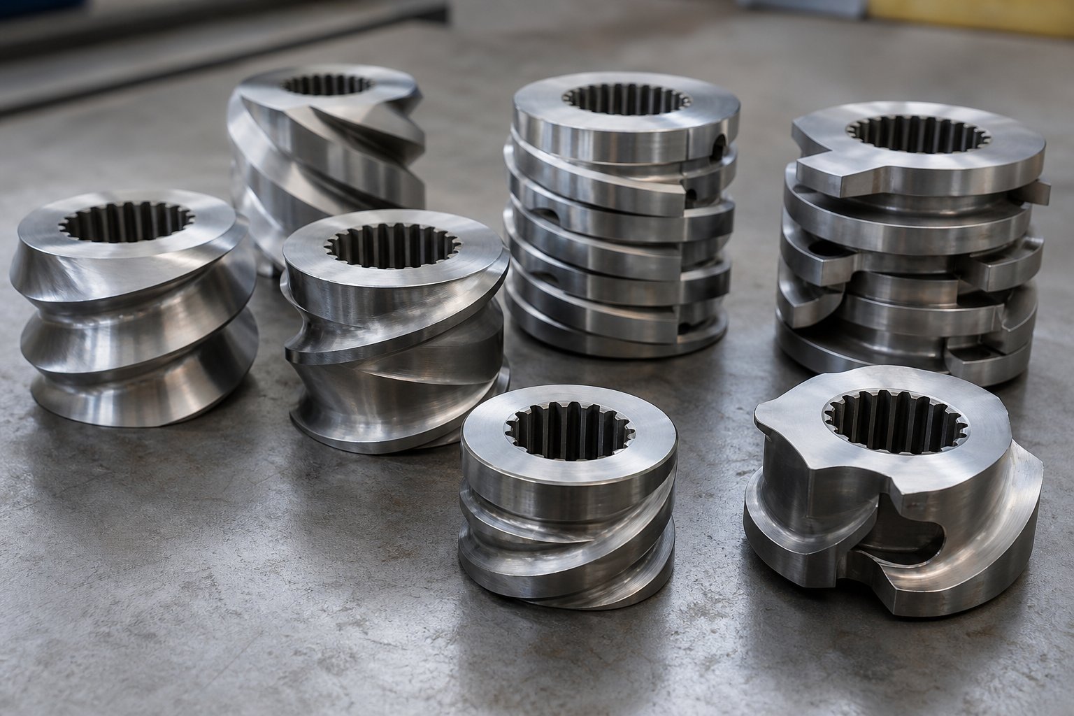
Modular Screw Element Design and How Element Arrangement Affects Processing
Here is the part of twin-screw technology that most resources gloss over — and it happens to be the part that matters most. Every extruder screw in a co-rotating machine is not a single machined piece. It is a modular assembly of individual elements, each slid onto a common splined shaft and locked into position. Change one element, and you change the processing behavior in that zone. Rearrange the entire sequence, and you have essentially built a different machine.
This modularity is precisely why twin screws can handle everything from delicate pharmaceutical blends to heavily filled engineering compounds. But to leverage it, you need to understand what each element type actually does to the material passing through it.
Conveying Elements and Their Pitch Variations
Conveying elements are the workhorses of material transport. They look like traditional helical flights wrapped around the shaft, and their job is straightforward: move material forward. What makes them interesting is how pitch — the axial distance between consecutive flights — controls the character of that movement.
Imagine two scenarios. A wide-pitch element acts like a fast conveyor belt: it moves material rapidly with minimal compression, keeping the channel only partially filled. Shear is low, pressure build-up is modest, and material spends very little time in that zone. This is exactly what you want in the solids conveying section near the feed throat, where the priority is getting pellets or powder downstream without premature melting or surging.
A tight-pitch element does the opposite. It slows material down, increases the degree of fill within the channel, and generates significant forward pressure. You will find these elements positioned near the die end, where stable metering pressure is essential for consistent output, and upstream of kneading zones, where fully filled channels ensure that mixing elements work on a continuous melt phase rather than a partially starved stream.
Between these extremes, engineers use graduated pitch transitions — progressively tightening the lead along the barrel — to control melting behavior and avoid abrupt pressure spikes. A screw design reference from NC State Extension notes that channel depth decreases in the order conveying > compression > metering zone, reinforcing the idea that conveying elements are not passive hardware but active tools for managing fill level, pressure profile, and residence time along the entire barrel length.
One common mistake is relying on conveying elements alone for mixing. They do generate some shear as melt is dragged through helical channels, but it is nowhere near enough to distribute pigments evenly or break apart filler agglomerates. For that, the plastic extruder screw profile needs a fundamentally different class of element.
Kneading Blocks, Mixing Elements, and Reverse Elements
If conveying elements are the transportation network, kneading blocks are the processing engines. A kneading block consists of multiple lobed discs stacked on the shaft, each offset from its neighbor by a defined stagger angle. Three design variables control how aggressively a kneading block works:
- Stagger angle — This is the angular offset between adjacent discs. A low angle (around 30°) promotes forward conveying with moderate shear — ideal for distributive mixing, where the goal is to spread additives evenly without generating excessive heat. A steep angle (60° or 90°) restricts forward flow, forces material to recirculate, and produces intense shear stress and pressure fluctuations. These high-stagger configurations excel at dispersive mixing — physically shattering pigment agglomerates, carbon black clusters, or tightly bonded filler particles.
- Disc width — Narrower discs create more frequent changes in flow direction over a given axial length, intensifying local pressure gradients and extensional flow. Wider discs produce smoother, gentler flow paths. As a rule, narrow discs boost dispersive action while wide discs favor distribution.
- Number of discs (block length) — More discs in a block mean longer residence time in that mixing zone and greater cumulative energy input. Shorter blocks provide a localized mixing effect without drastically raising melt temperature or torque.
Beyond stagger angle, kneading blocks come in three conveying orientations that fundamentally alter their behavior:
- Forward kneading blocks — Net positive conveying effect. They mix while still pushing material downstream, making them useful where moderate mixing is needed without excessive back-pressure.
- Neutral kneading blocks (90° stagger) — Zero net conveying. Material oscillates back and forth across the block, dramatically increasing residence time and energy input. These are aggressive mixers, often placed where intensive homogenization is required.
- Reverse kneading blocks — Negative conveying effect. They actively push material backward against the overall flow direction, creating a restrictive dam that forces upstream zones to fill completely. This back-pressure is critical for building melt seals ahead of vent ports and for delivering maximum dispersive mixing intensity.
Specialized elements round out the toolkit. Toothed mixing elements (TME) feature rows of protruding teeth that repeatedly split and recombine the melt with minimal forward or backward pumping effect — pure distributive mixing with very little added shear. They are especially valuable for heat-sensitive formulations where you need uniform composition without temperature overshoot. Comb mixing elements (ZME) work on a similar principle, using interrupted flights to divide the melt flow into many small streams that recombine further down the channel.
The interplay between these element types is what gives a plastic extrusion screw its character. Aggressive dispersive mixing from narrow-disc, high-stagger kneading blocks can deliver exceptional pigment dispersion — but at the cost of elevated melt temperature and higher torque demand. Gentler distributive elements preserve molecular weight and fiber length but may leave agglomerates intact. The art lies in sequencing both types strategically along the barrel.
Designing a Screw Profile for Specific Outcomes
Sounds complex? It is — but the logic follows a consistent pattern. Engineers design screw profiles by mapping each barrel zone to a processing task, then selecting the element type that best accomplishes that task without compromising downstream performance.
Consider three common applications. Each demands a very different arrangement of the same modular building blocks:
| Zone | Color Masterbatch Compounding | Glass-Fiber Reinforced Compound | Reactive Extrusion |
|---|---|---|---|
| Feed / Solids Conveying | Wide-pitch conveying elements for fast, low-shear intake of pellets and pigment powder | Wide-pitch conveying elements; side feeder port reserved downstream for fiber introduction | Wide-pitch conveying elements with controlled feed rate for stoichiometric dosing |
| Melting / Plastication | Gradual pitch reduction with mild forward kneading blocks to melt base resin | Moderate kneading blocks to melt resin before fiber addition | Short, gentle kneading zone to melt polymer without premature reaction initiation |
| Primary Mixing | High-stagger (60°–90°) narrow-disc kneading blocks for aggressive dispersive mixing to break pigment agglomerates to single-particle level | Mild distributive mixing elements (wide-disc, low-stagger) to wet-out and distribute fibers without excessive breakage | Forward kneading blocks at moderate stagger for controlled distributive mixing; residence time tuned for reaction kinetics |
| Venting / Devolatilization | Conveying elements with increased pitch to reduce fill; atmospheric vent for moisture removal | Conveying elements at vent zone; vacuum vent to remove moisture absorbed by hygroscopic glass fibers | Reverse elements create strong melt seal; vacuum vent removes reaction by-products and residual monomers |
| Secondary Mixing / Homogenization | TME or low-stagger kneading blocks for final distributive polishing of color uniformity | Short conveying section only — no additional mixing to preserve fiber length | Neutral or reverse kneading blocks to extend residence time and drive reaction to target conversion |
| Metering / Pressurization | Tight-pitch conveying elements to build stable die pressure for strand pelletizing | Tight-pitch conveying elements for consistent die pressure and uniform strand diameter | Tight-pitch conveying elements; precise pressure control to avoid foaming from residual volatiles |
Notice the pattern: the same six zones appear in every profile, but the element choices within each zone shift dramatically based on what the material needs. A color masterbatch demands brutal dispersive intensity in the mixing zone because pigment agglomerates must be shattered to achieve acceptable color strength and transparency. A glass-fiber compound, by contrast, requires the gentlest possible mixing after fiber introduction — every unnecessary kneading disc shortens fibers and degrades final mechanical properties. Reactive extrusion sits somewhere in between, prioritizing residence time control and by-product removal over raw mixing intensity.
This is the real power of the twin-screw platform. A single machine frame, gearbox, and motor can serve dozens of applications simply by reconfiguring the modular elements on the shaft. An engineer designing a screw profile for a new formulation is not buying a new machine — they are rearranging the building blocks to create a custom processing pathway tailored to the material's rheology, thermal sensitivity, and mixing requirements.
Yet even a perfectly designed screw profile means little if you cannot evaluate the machine it sits inside. Specification sheets for twin-screw extruders are packed with numbers — screw diameter, L/D ratio, torque density, free volume — that look opaque until you understand what each parameter actually controls and how they interact to define a machine's processing envelope.
How to Read Twin-Screw Extruder Specifications Like an Engineer
Open any twin screw extruder machine datasheet and you will see a wall of numbers — screw diameters in millimeters, L/D ratios expressed as cryptic ratios, torque densities in Nm/cm³, and motor power ratings in kilowatts. For someone evaluating a twin screw extruder for sale or comparing quotes from different twin screw extruder manufacturers, these figures can feel like a foreign language. Yet every one of them describes a specific capability limit of the machine. Learn to read them, and you can predict whether a given extruder will meet your process demands before you ever run a trial.
Screw Diameter and L/D Ratio Explained
Screw diameter is the single most fundamental sizing parameter. It defines the scale of everything else — barrel bore, free volume, throughput capacity, and even price. A 27 mm lab scale twin screw extruder designed for formulation development handles grams-per-minute throughputs, while a 140 mm production machine processes thousands of kilograms per hour. As a general volumetric scaling principle, throughput capacity increases roughly with the cube of the diameter ratio: doubling the screw diameter can yield approximately eight times the output, assuming the process is not limited by heat transfer or devolatilization. Industry references from Plastics Today express this relationship as Qtarget = Qreference × (ODtarget / ODreference)³, though the exponent drops toward 2.0 for heat-transfer-limited processes and to roughly 2.3–2.7 for devolatilization-heavy applications.
L/D ratio — the total barrel length divided by the screw diameter — tells you how many processing zones the machine can accommodate. A 32:1 ratio provides enough length for basic compounding with a single vent, while 48:1 to 52:1 ratios support multiple mixing stages, sequential venting, and downstream side feeding. Some specialty configurations stretch to 60:1 or even 68:1 for processes like reactive extrusion or multi-stage devolatilization that demand extended residence time. When reviewing a twin-screw extruder machine specification, always consider L/D alongside diameter: a 50 mm extruder at 48:1 offers far more process flexibility than the same diameter at 32:1, even though the screw size is identical.
Torque Density, Specific Torque, and Free Volume
Torque density is arguably the most important — and most misunderstood — number on a specification sheet. Expressed in Nm/cm³, it measures how much mechanical energy the gearbox and shaft assembly can deliver per unit of available screw volume. A higher torque density means the machine can process higher-viscosity melts, push through more restrictive dies, and handle tougher formulations before the drive system reaches its limit. Modern co-rotating machines achieve torque densities around 18 Nm/cm³, a significant leap over older-generation designs that operated below 12 Nm/cm³.
Specific torque normalizes the total shaft torque against screw diameter, making it possible to compare machines of different sizes from different twin screw extruder manufacturers on a level playing field. Two extruders may both claim 3,000 Nm of total torque, but if one achieves that number on a 50 mm shaft and the other on a 75 mm shaft, the smaller machine has a significantly higher specific torque — and, practically speaking, more usable power relative to its throughput capacity.
Free volume — the open cross-sectional area available for material inside the barrel — determines how much bulk feedstock the screws can physically accept. It is closely tied to the OD/ID ratio (outside diameter divided by inside diameter of the screw). A higher OD/ID ratio, such as 1.66 versus 1.55, yields substantially more free volume at the same nominal screw diameter. Leistritz technical data illustrates this clearly: comparing a 70 mm machine at 1.55 OD/ID with 240 cc/dia to a 75 mm machine at 1.66 OD/ID with 300 cc/dia reveals a 30% throughput advantage for the higher-volume geometry — a difference invisible if you only compare screw diameters.
Here is a framework for evaluating these critical specifications side by side:
| Specification | What It Measures | Typical Range | Why It Matters |
|---|---|---|---|
| Screw Diameter (mm) | Fundamental machine size and throughput scale | 20–200+ mm | Determines output capacity, barrel bore, and price class; lab scale extruder sizes start around 12–27 mm |
| L/D Ratio | Available processing length relative to diameter | 32:1 to 52:1 (up to 68:1) | Longer ratios accommodate more mixing, venting, and reaction zones |
| Torque Density (Nm/cm³) | Mechanical energy per unit of screw volume | 10–18+ Nm/cm³ | Higher values handle viscous melts and high-filler formulations without stalling |
| Specific Torque (Nm/a³) | Total torque normalized to screw diameter cubed | Manufacturer-specific | Enables fair cross-manufacturer comparison independent of machine size |
| Free Volume (cc/dia) | Open channel volume per diameter of screw length | 1–300+ cc/dia | Dictates bulk material intake capacity; critical for low-density powders and high-fill processes |
| OD/ID Ratio | Ratio of screw outer diameter to inner (root) diameter | 1.22 to 1.80 | Higher ratio increases free volume and reduces average channel shear rate |
| Max Screw Speed (RPM) | Maximum rotational speed of screws | 300–1,200+ RPM | Higher speeds increase shear rate, throughput potential, and energy input |
| Motor Power (kW) | Total installed drive power | 5–800+ kW | Sets the upper energy limit; must match torque demand at operating speed |
Maximum Screw Speed and Power Rating
Maximum screw speed, reported in RPM, directly governs shear rate and throughput potential. A machine rated for 1,200 RPM can push material through the barrel much faster — and generate far more shear — than one limited to 300 RPM. High-speed capability is valuable for processes like masterbatch compounding, where aggressive dispersive mixing benefits from elevated shear rates, and for maximizing production throughput on a given diameter platform.
Motor power connects to speed through a fundamental relationship: Torque (Nm) = 9,550 × Power (kW) ÷ RPM. This means a 200 kW motor geared for 600 RPM delivers the same shaft torque as a 400 kW motor geared for 1,200 RPM. If your process operates entirely below 600 RPM, investing in the larger motor provides no torque advantage — only additional cost. The practical takeaway? Match the motor and gearbox ratio to your actual operating speed range, not to the highest number on the catalog page.
For R&D teams working with limited raw material quantities, a benchtop twin screw extruder with a small diameter (12–27 mm) and proportionally lower power rating allows meaningful formulation trials at gram-level batch sizes. The same specification logic applies at this scale: torque density, L/D ratio, and free volume still dictate what the machine can process. The only difference is the throughput window, which on a lab scale extruder may range from under one kilogram per hour up to about fifty — enough to produce test samples, validate screw configurations, and generate scale-up data for production-class equipment.
Knowing how to decode these numbers transforms the twin screw extruder price conversation from a comparison of sticker costs into a comparison of processing capability per dollar invested. Yet specifications alone describe potential. Realizing that potential — and understanding where a twin-screw machine genuinely outperforms a single-screw alternative — requires a direct, metric-by-metric comparison between the two architectures.
Twin-Screw vs Single-Screw Extruder Performance Comparison
Specifications tell you what a machine can do. But how does a double screw extruder actually stack up against its single-screw counterpart in real processing situations? The answer is more nuanced than "twin-screw is better" — and understanding the differences at a mechanistic level is the fastest way to avoid buying more machine than you need, or worse, not enough.
Fundamental Differences in Conveying and Mixing Mechanisms
The gap between these two architectures starts at the most basic level: how material moves through the barrel.
A single-screw extruder relies on friction-driven conveying. Solid pellets advance because they grip the barrel wall more than the screw surface — meaning output is directly tied to the friction properties of the feedstock. Change the resin grade, switch from pellets to powder, or introduce a slippery additive, and the conveying behavior shifts unpredictably. Mixing is limited to what happens passively as melt circulates within the helical channel. There is no mechanical interlock forcing material to recombine or redistribute.
A double screw extruder machine with intermeshing geometry operates on a fundamentally different principle: positive-displacement conveying. The flight of one screw sweeps through the channel of the other, physically pushing material forward regardless of its friction coefficient. This is why twin-screw systems handle powders, sticky blends, recycled flakes, and slippery polymers with equal consistency. The machine moves what you feed it — reliably and measurably.
This positive-displacement mechanism also enables starve-fed operation, where a separate feeder controls the material input rate independently of screw speed. Engineers can then adjust screw RPM to change shear intensity and mixing energy without altering throughput — a degree of process decoupling that single-screw designs, which are inherently flood-fed, simply cannot replicate.
Performance Comparison Across Key Metrics
Rather than relying on vague generalizations, here is a structured comparison across the metrics that matter most when selecting a screw extruder for a specific application:
| Performance Metric | Single-Screw Extruder | Twin-Screw Extruder |
|---|---|---|
| Throughput Flexibility | Output tightly coupled to screw speed; limited independent control | Feed rate and screw speed independently adjustable; wide operating window |
| Distributive Mixing | Low — relies on passive channel recirculation | High — figure-eight flow path and modular mixing elements ensure uniform additive distribution |
| Dispersive Mixing | Very limited — insufficient shear to break agglomerates consistently | High — configurable kneading blocks generate targeted shear stress for agglomerate breakup |
| Shear Rate Control | Narrow range; dictated by fixed screw geometry | Broad range; adjustable via element selection, screw speed, and feed rate ratio |
| Residence Time Distribution | Broad — material can stagnate in dead zones | Narrow — self-wiping geometry ensures uniform processing history |
| Venting Capability | Limited; difficult to create reliable low-pressure zones | Excellent; multiple vent ports with vacuum capability for effective devolatilization |
| Material Versatility | Best with pre-compounded pellets of consistent properties | Handles powders, pellets, flakes, liquids, recycled feedstock, and variable-bulk-density materials |
| Equipment Cost | Lower initial investment | Higher capital cost due to complex gearbox, barrel, and screw assemblies |
| Operating Cost | Lower energy and maintenance burden for simple processes | Higher per-hour cost, offset by fewer processing steps and better first-pass yield |
| Maintenance Complexity | Simpler — fewer wear parts, straightforward screw removal | More involved — modular elements require periodic inspection and replacement, especially in abrasive applications |
The pattern is clear: screw extruders built on the twin-screw platform dominate wherever the process demands mixing, material flexibility, or precise residence time control. Single-screw machines win on simplicity and cost efficiency when those capabilities are unnecessary.
When a Single-Screw Extruder Is the Better Choice
Credibility demands honesty. A twin-screw machine is not always the right answer, and treating it as one leads to overspending and unnecessary operational complexity.
Single-screw extruders remain the preferred choice — and often the superior choice — in several well-defined scenarios:
- Profile and pipe extrusion from pre-compounded pellets — When the material arrives as a fully formulated, homogeneous pellet, the extruder's job is simply to melt it and deliver a stable, pressurized melt stream to the forming die. A single screw does this efficiently, reliably, and at lower cost per kilogram.
- Film blowing and cast film production — These processes prioritize consistent melt pressure and temperature uniformity at the die lip. Single-screw extruders, especially high-performance barrier-screw designs, deliver the steady melt stream these applications require.
- High-volume production of commodity products — PE water pipe, PP sheet, and PVC profiles produced from stable compounds represent enormous global volumes. The simplicity and proven reliability of a single-screw extruder for polymer forming — not compounding — make it the economically rational choice.
- Wire and cable coating — Crosshead extrusion for jacketing and insulation relies on metering accuracy and pressure stability. Single-screw platforms with precision metering zones handle these duties well.
The decision framework comes down to one question: does the process require the material to be mixed inside the extruder, or only melted and shaped? If mixing already happened upstream — at the compounding plant, in a reactor, or through pre-blending — a single-screw machine is often the smarter investment. If the extruder itself must compound, devolatilize, react, or homogenize, the twin-screw architecture becomes essential.
Selecting the right architecture, however, is only the starting point. Even the ideal machine delivers suboptimal results if its process parameters — screw speed, feed rate, barrel temperature profile, and torque — are not tuned to the specific material and formulation passing through it.
Critical Process Parameters and How to Optimize Them
A perfectly specified machine with an expertly designed screw profile can still produce off-spec material if the process parameters are wrong. Screw speed, feed rate, barrel temperatures, and torque do not act independently — they form an interconnected web where adjusting one variable shifts every other. Mastering a compounding extruder means understanding these interactions deeply enough to diagnose problems from the control panel and make targeted corrections rather than chasing symptoms in circles.
This is the area where most technical resources fall silent. Screw design gets attention. Machine specifications get published. But the minute-to-minute decisions that actually determine product quality — how fast to spin the screws, how much to feed, what temperature to set in zone four — are rarely explained with the clarity they deserve. Let's fix that.
Screw Speed, Feed Rate, and Their Interaction
Think of screw speed and feed rate as two dials that control the same machine in fundamentally different ways. Screw speed (RPM) governs how much mechanical energy the screws deliver to the material: higher RPM means higher shear rates, more intensive mixing, and faster surface renewal in devolatilization zones. Feed rate (kg/h) determines how much material occupies the barrel at any given moment — the degree of fill.
Here is where things get interesting. In a twin screw compounding extruder operating in starve-fed mode, these two variables are independently controllable. Unlike a flood-fed single-screw extruder — where the hopper is full and output is locked to screw speed — a starve-fed system uses a separate gravimetric or volumetric feeder to meter material into the barrel. The screws are only partially filled in most zones, and the feeder, not the screw, dictates throughput.
This independence creates a powerful tuning lever called specific throughput, defined as kilograms per hour divided by RPM (kg/h/RPM). Imagine you are running a polymer extruder at 500 RPM and feeding 200 kg/h. Your specific throughput is 0.40 kg/h/RPM. If you want more intensive mixing without changing output, you can increase screw speed to 700 RPM while keeping the feed rate at 200 kg/h. The specific throughput drops to 0.29 kg/h/RPM — meaning each kilogram of material now spends more time under the screws and encounters more kneading action. The material "feels" a more aggressive mixing experience even though production volume has not changed.
Conversely, raising the feed rate at constant RPM increases fill level and reduces the mixing intensity per kilogram. Leistritz technical literature describes this relationship directly: feed rate versus screw RPM, combined with the screw design and temperature profile, regulates the mass transfer and mixing properties of the process. Highly dispersive applications — color masterbatch for thin film, for instance — run at comparatively lower specific throughput to maximize the time material spends in shear-intensive kneading zones.
When should you adjust speed versus feed? A simple rule applies: if mixing quality is insufficient, reduce specific throughput (increase RPM or reduce feed rate). If melt temperature is too high or degradation appears, increase specific throughput (reduce RPM or raise feed rate) to lower specific energy input. This single ratio gives you more direct control over product quality than any other operator-adjustable variable.
Barrel Temperature Profile and Thermal Management
Walk along the barrel of any compounding twin screw extruder and you will see a series of independent heating and cooling zones, each set to a different temperature. This zone-by-zone profile is not arbitrary — it follows a deliberate thermal strategy matched to the material's behavior at each processing stage.
The feed zone is typically set cooler than downstream zones, often below the polymer's melting point. Why? Premature melting in the feed throat creates a sticky, adhesive layer on the screw surface that disrupts solids conveying and starves downstream zones. Some operations even use water-cooled feed barrels to keep incoming pellets or powders flowing freely.
Melting and mixing zones require precise temperature control tuned to the polymer's processing window. Setting barrel temperatures too low forces the screws to do all the melting work mechanically, driving up shear stress, torque demand, and the risk of localized overheating. Setting them too high causes premature melting before the material reaches kneading elements, reducing mixing efficiency because fully molten polymer flows around mixing elements rather than being forced through them under compression.
The die-end zones often need careful management for an entirely different reason: preventing thermal degradation. Material in the metering section is fully molten, under pressure, and exposed to heat from both the barrel wall and internal viscous dissipation. If the barrel set temperature in this region is unnecessarily high, the melt can overshoot its thermal stability limit — causing discoloration, chain scission, or off-gassing that ruins the final product.
Viscous dissipation — sometimes called shear heating — is the elephant in the room of thermal management. Every time material passes through a kneading block or gets dragged through the clearance between screw flight and barrel wall, mechanical energy converts to heat inside the melt. At high screw speeds, this self-generated heat can easily exceed the barrel set temperature, meaning the barrel's cooling system is actually trying to remove heat rather than add it. As research published on AZoM emphasizes, without exception, elevated melt temperature results in degradation of polymer formulations — making barrel cooling capacity just as important as heating capacity in high-speed compounding operations.
A practical consequence: the melt temperature you measure at the die is almost never equal to the barrel set temperature. It is the result of barrel heating, barrel cooling, screw-generated shear heat, and the polymer's own thermal conductivity interacting simultaneously. Experienced operators learn to read this difference as a diagnostic signal. A melt temperature significantly above the set point indicates excessive shear input — a cue to reduce RPM, open up kneading zone geometry, or increase barrel cooling flow.
Torque Monitoring and Residence Time Distribution
Your control panel displays torque as a percentage of maximum gearbox capacity, and that single number carries more diagnostic information than almost any other readout on the machine.
Torque reflects the total resistance the screws encounter while turning. Higher melt viscosity, tighter kneading blocks, greater fill levels, and lower melt temperatures all increase torque. A stable torque reading — say, fluctuating within a 2–3% band — signals a steady-state process with consistent feed, uniform melting, and predictable die pressure. A drifting or spiking torque reading tells you something is changing: feed rate inconsistency, incomplete melting sending solid chunks into the mixing zone, or barrel temperature deviations altering melt viscosity.
Torque also sets a hard operating boundary. If the gearbox reaches 100% of its rated capacity, the machine will either alarm or shut down to protect the drive train. Running a fractional melt index HDPE or a high-viscosity engineering resin may push torque to this limit well before reaching the desired throughput. Leistritz engineering notes identify torque-limited processes as a common boundary condition in twin-screw extrusion, recommending strategies such as removing several kneading elements from the screw profile or increasing zone temperature setpoints in the melting zone to reduce melt viscosity and free up torque headroom.
Residence time distribution (RTD) addresses a different dimension of process quality. RTD describes the statistical spread of how long individual material particles remain inside the barrel. A narrow RTD means every particle receives nearly the same thermal and mechanical history — critical for heat-sensitive polymers where a few extra seconds at elevated temperature can trigger degradation, and for reactive extrusion where consistent reaction time ensures uniform conversion.
Co-rotating intermeshing machines inherently produce narrower RTDs than other configurations due to their self-wiping geometry. Still, the screw profile can widen or narrow the distribution. Backward-mixing elements and neutral kneading blocks increase RTD spread by recirculating material, while a streamlined conveying profile with minimal restriction keeps it tight. Higher throughput at constant screw speed also compresses RTD, as process data from Thermo Fisher Scientific demonstrates — a larger throughput reduces both the average residence time and the width of the distribution.
Bringing all of these parameters together into a coherent optimization workflow requires a systematic approach. Here is a practical checklist that engineers can reference during process development on any compounding extruder:
- Establish a baseline — Set barrel temperatures to the resin supplier's recommended profile, start at moderate screw speed (40–60% of maximum), and begin feeding at a conservative rate. Record torque, melt temperature, and die pressure.
- Adjust specific throughput for mixing quality — If dispersion or distributive uniformity is inadequate, reduce specific throughput (raise RPM at constant feed rate). If melt temperature exceeds the target, increase specific throughput (raise feed rate or lower RPM).
- Fine-tune barrel temperatures zone by zone — Keep the feed zone cool enough to maintain solid conveying. Increase melting zone temperatures only if torque is excessively high. Reduce die-end zone temperatures if melt temperature at the die overshoots the target.
- Monitor torque as a stability indicator — Aim for a steady reading between 50% and 80% of maximum capacity. Below 40% suggests the machine is under-utilized; above 90% leaves no headroom for process upsets.
- Check melt temperature against barrel set temperature — A gap of more than 15–20 °C above the set point often signals excessive shear heating. Consider reducing RPM, widening kneading disc stagger angles, or increasing cooling flow.
- Evaluate residence time if degradation occurs — Shorten RTD by increasing throughput or removing restrictive elements. Extend RTD only when reactive conversion or devolatilization efficiency demands it.
- Validate vent performance — Confirm that vent ports show no material escape (vent flow). If vent flow occurs, strengthen the upstream melt seal or reduce fill level in the venting zone.
- Document every change — Record the specific throughput, torque %, melt temperature, and product quality result for each parameter set. Optimization is iterative, and data from previous runs eliminates redundant trials.
Every point on this checklist ultimately ties back to one principle: the relationship between mechanical energy input, thermal energy input, and the time the material spends receiving both. Master that three-way balance, and you control the process. Ignore it, and the process controls you.
Parameter optimization, of course, does not exist in a vacuum. The reason you tune screw speed, temperature, and torque differently for a mineral-filled compound than for a pharmaceutical blend is because each application places fundamentally different demands on the machine — demands rooted in material behavior, regulatory requirements, and end-product performance criteria that vary enormously across industries.
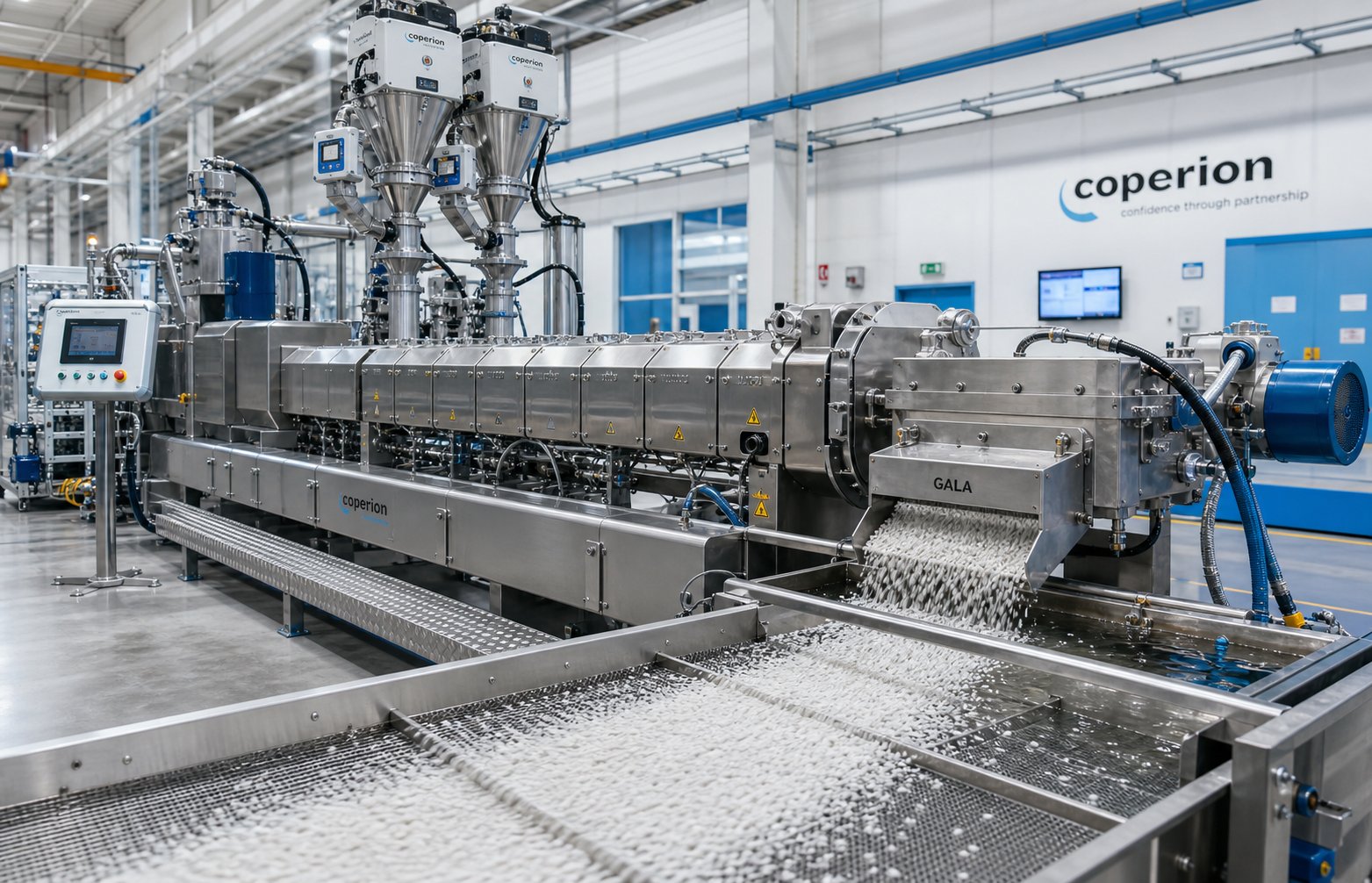
Applications Where Twin-Screw Extruders Are the Only Right Choice
Plenty of resources will hand you a bullet-point list of industries that use twin-screw technology. Plastics. Food. Pharma. Chemicals. That list tells you where these machines show up — but it tells you nothing about why they are irreplaceable in each context. The real question is: what specific processing challenge does each application present, and why does the twin-screw platform solve it better than any alternative?
Answering that question reveals patterns that apply far beyond any single industry. It also explains why the twin screw extruders market continues to expand into sectors — battery manufacturing, continuous drug production, biodegradable packaging — that would have seemed unlikely just a decade ago.
Compounding, Masterbatch, and Filled Polymer Production
Compounding is the application that built the twin-screw industry, and it remains the largest single use case. The reason is rooted in mixing physics rather than tradition.
Every compounding operation must accomplish two distinct mixing tasks simultaneously. Distributive mixing spreads additives — pigments, stabilizers, flame retardants — uniformly throughout the polymer matrix so that every pellet leaving the die contains the same concentration. Dispersive mixing goes further: it applies enough shear stress to physically shatter agglomerates into individual particles. A carbon black pellet, for example, is not a single particle but a loosely bonded cluster of nanoscale aggregates. Unless the extruder breaks these clusters apart, the final product will show specks, uneven color, and inconsistent conductivity. Industry expert Kenneth Russell explains that a material can be distributed but not dispersed — resulting in large agglomerates spread evenly through the polymer — or dispersed but not distributed, with fine particles concentrated in one region. Only a co-rotating twin-screw platform delivers both actions in a single pass, thanks to its configurable kneading blocks and self-wiping geometry.
Consider some of the most demanding formulations a plastic twin screw extruder handles daily:
- Color masterbatch — Pigment agglomerates must be reduced to single-particle dimensions to achieve full color strength and avoid specks in thin-wall injection molding or blown film. High-stagger kneading blocks (60 degree to 90 degree) with narrow disc widths deliver the intense dispersive shear required, while downstream distributive elements ensure uniform pigment concentration across the melt cross-section.
- Carbon black compounds — Conductive and UV-protective carbon black grades have an extremely high surface energy that promotes re-agglomeration. The continuous self-wiping action of intermeshing screws prevents stagnant pockets where these particles can re-cluster, maintaining dispersion quality from mixing zone to die exit.
- Glass-fiber reinforced compounds — Chopped glass fibers are introduced downstream via a side stuffer after the polymer has melted. Gentle distributive mixing elements wet out the fibers without excessive breakage. Every unnecessary kneading element shortens average fiber length and degrades final mechanical properties — a sensitivity that demands the precise element-by-element screw configurability only twin-screw machines provide.
- Mineral-filled systems — Calcium carbonate, talc, and barium sulfate loadings can exceed 70% by weight. These highly abrasive fillers accelerate wear on screw flights and barrel liners, making barrel metallurgy and wear resistance critical factors in maintaining output consistency over time. Operations running high-mineral formulations often schedule barrel inspections at shorter intervals and source replacement components specifically engineered for abrasion resistance.
In mineral-filled and glass-fiber compounding, barrel quality directly affects both product quality and maintenance economics. Worn barrel bores increase clearance between the screw flight and the barrel wall, allowing material to leak backward and reducing self-wiping efficiency. For operations that need replacement barrels built for these high-wear environments, suppliers like NANHAIYA offer a parallel twin screw barrel designed specifically for compounding, masterbatch, and pelletizing applications where abrasion resistance is non-negotiable.
Recycling, Pelletizing, and Reprocessing Operations
Recycled feedstocks are, by nature, inconsistent. Bulk density varies from flake to flake. Moisture content swings with weather and storage conditions. Residual contaminants — trace polymers, adhesive residues, printing inks — show up unpredictably. A twin screw extruder plastic recycling line thrives in this environment precisely because its starve-fed operation and modular screw design can accommodate variability that would overwhelm a simpler machine.
Here is what happens in a typical post-industrial or post-consumer reclaim process on a co-rotating platform:
- Variable bulk density management — Recycled flakes and regrind have far lower and more inconsistent bulk density than virgin pellets. Gravimetric feeders, often paired with crammer devices, meter this unpredictable stream into the barrel at a controlled rate. The starve-fed screw design accepts whatever volume arrives without surging or bridging.
- Devolatilization of moisture and contaminants — Recycled plastics almost always carry higher moisture levels than virgin resin, and washing steps in post-consumer recycling introduce additional water. Multi-stage vacuum venting — enabled by the screw's ability to create sequential low-pressure zones — strips moisture and volatile contaminants without a separate drying step. Charlie Martin of Leistritz notes that PET and PLA edge-trim reclaim processes use twin-screw devolatilization to avoid pre-drying entirely, reducing energy costs and minimizing IV loss from hydrolysis.
- Melt filtration integration — Screen changers positioned at the barrel discharge remove particulate contaminants — paper fibers, metal fragments, cross-linked gels — before the melt reaches the pelletizing die. The twin-screw machine's ability to generate stable, moderate pressures (typically below 1,500 psi in normal operation) allows integration with continuous screen changers for uninterrupted production.
- Screw extruder granulator systems — After filtration, the clean melt is converted into uniform pellets through strand pelletizers, underwater pelletizers, or water-ring systems. The result is a recycled pellet with consistent geometry and composition — ready for direct use in injection molding or film extrusion, or for further value-added compounding with fillers and additives.
One important caveat deserves mention. As Martin emphasizes, the closely intermeshing geometric tolerances inherent in twin-screw machines make them unsuited for processing recycled feedstocks with high degrees of contamination — a stray bolt or metal fragment can damage screw elements and lock the machine. Post-consumer streams with heavy contamination often pair a single-screw pre-extruder for initial melting and coarse filtration with a downstream twin screw plastic extruder for compounding and fine devolatilization, combining the strengths of both architectures.
Recycling applications also place intense wear demands on barrels, particularly when processing post-consumer streams loaded with mineral contaminants or glass-fiber residues from mixed waste. Sourcing wear-resistant replacement barrels — with bimetallic or powder metallurgy liners — becomes a routine part of maintaining consistent output quality in these demanding environments.
Emerging Applications Driving Industry Growth
The twin-screw platform's versatility has carried it well beyond traditional plastics compounding. Several advanced applications are expanding rapidly, each driven by specific processing requirements that align precisely with the machine's strengths. Laboratory extruders play a vital role in many of these emerging fields, enabling researchers to develop and validate new processes at small scale before committing to production equipment.
- Battery electrode manufacturing — Lithium-ion battery production traditionally uses planetary mixers to prepare electrode slurries in four-to-eight-hour batch cycles. Twin-screw compounding offers a continuous alternative that reduces mixing time to minutes, improves dispersion quality, and — critically — enables solvent-free or reduced-solvent electrode processing. Research from Thermo Fisher Scientific demonstrates that the higher shear forces in a twin-screw extruder produce narrower particle size distributions than planetary mixers, reducing downstream screen filter blockages. The self-wiping geometry minimizes material loss compared to batch vessels, and the continuous process eliminates batch-to-batch variation entirely. Solvent-free dry electrode processing — where a polymeric binder is sheared to form a fibroid network between cathode active material particles — represents a potentially transformative approach that could eliminate the energy-intensive drying lines currently required in battery cell manufacturing.
- Continuous pharmaceutical manufacturing — FDA guidance increasingly supports continuous processing over traditional batch manufacturing for solid oral dosage forms. Twin-screw hot-melt extrusion disperses poorly soluble active pharmaceutical ingredients (APIs) into polymer carriers to create amorphous solid dispersions with dramatically improved bioavailability. The narrow residence time distribution ensures every particle of API receives identical thermal and mechanical history — a regulatory requirement for content uniformity. Twin-screw wet granulation, using the same platform with an open discharge instead of a die, converts powder blends into free-flowing granules suitable for tablet compression.
- Biodegradable polymer compounding — PLA, PBAT, PHA, and starch-based blends present unique processing challenges: narrow thermal windows, sensitivity to moisture-induced degradation, and the need for precise additive incorporation to achieve target mechanical and barrier properties. Twin-screw machines handle these constraints through zone-by-zone temperature control, multi-stage devolatilization for moisture removal, and gentle distributive mixing that avoids excessive chain scission. Industry testing confirms that PLA compounding on twin-screw platforms requires careful management of shear and temperature to prevent hydrolytic degradation — a level of control that simpler extrusion architectures cannot provide.
- 3D printing filament production — Consistent filament diameter is the single most critical quality attribute for fused deposition modeling (FDM). Twin-screw extruders compound custom polymer blends — carbon-fiber-filled nylon, conductive PLA, flexible TPU with color additives — and deliver a homogeneous melt to a precision filament die. The starve-fed operation and narrow residence time distribution prevent the thermal degradation and compositional variation that would cause diameter fluctuations and printing defects downstream.
- Polyester extruder applications for specialty fibers — Recycled PET and specialty polyester formulations are compounded with nucleating agents, chain extenders, and impact modifiers on twin-screw platforms before being spun into fibers or extruded into sheet. The machine's devolatilization capability removes residual moisture that would otherwise trigger hydrolysis and IV drop during melt processing.
Each of these emerging applications reinforces the same core principle: when a process demands precise control over mixing intensity, thermal history, and material residence time — simultaneously — the twin-screw platform is not merely a good option. It is often the only viable one.
Yet even the most capable machine is only as reliable as its most wear-prone components. The barrel and screw elements that enable all of this processing versatility operate under extreme conditions — high temperatures, abrasive fillers, corrosive additives — and their condition directly determines whether the extruder delivers consistent output or slowly drifts out of specification.
Barrel and Screw Components That Drive Processing Quality
Every parameter you optimize, every screw profile you design, and every formulation you develop ultimately depends on the physical condition of two components: the barrel and the screw. These are not static hardware. They are active processing surfaces operating under extreme temperatures, pressures, and abrasive loads — and their gradual degradation is the single largest source of creeping quality loss in any extrusion operation.
Most discussions about extruder twin screw components stop at identification: here is the barrel, here is the screw, these are the heating bands. That barely scratches the surface. Understanding how barrel metallurgy affects heat transfer and wear life, when wear has progressed far enough to warrant replacement, and what to look for in a replacement supplier — these are the details that separate a line running at peak efficiency from one slowly hemorrhaging throughput and quality without anyone noticing.
How Barrel Segments Affect Heat Transfer, Wear Life, and Process Stability
Imagine the barrel as an active participant in processing rather than a passive housing. Every zone transfers heat into or out of the melt through the barrel wall. Every bore surface interacts with the screw flight tips to maintain the self-wiping clearance that prevents dead zones. Every millimeter of liner material stands between stable production and accelerating wear.
The metallurgy of the twin screw barrel determines how well it performs each of these roles. Three primary barrel construction technologies dominate the market, each suited to different processing environments:
- Nitrided steel barrels — Machined from a single piece of nitriding-grade alloy steel (typically 38CrMoAlA or equivalent), then surface-hardened by diffusing nitrogen into the bore at 500-550 degrees Celsius. The result is a hardened case roughly 0.4-0.6 mm deep with surface hardness of 950-1100 HV (approximately 65-70 HRC), while the core retains its original toughness. Nitrided barrels deliver excellent performance for clean polyolefin processing, standard PVC, and low-filler formulations — but once abrasive wear penetrates beyond that thin hardened case, the soft core is exposed and wear accelerates rapidly.
- Bimetallic barrels — These use a high-strength steel shell with a wear-resistant alloy liner centrifugally cast inside the bore. The liner thickness ranges from 1.5 mm to 3.0 mm — roughly three to six times the effective wear depth of a nitrided surface. Liner alloys are selected based on the dominant wear mode: iron-based (Fe-Cr-B) alloys for general abrasion, nickel-based (Ni-Cr-B-W) alloys for combined corrosive and abrasive environments like PVC compounding, and tungsten-carbide-rich compositions for severely abrasive applications such as glass-fiber reinforcement.
- Powder metallurgy (PM) alloy barrels — For the most extreme applications, barrel liners produced through hot isostatic pressing (HIP) of fine powder alloys offer the highest achievable combination of hardness, toughness, and corrosion resistance. PM liners can reach 70-75 HRC and resist both abrasion and chemical attack, making them the premium choice for long-campaign barrel extruder applications processing heavily filled engineering plastics or chemically aggressive compounds.
Why does liner composition matter so much? Because bore tolerances in a twin-screw machine are extraordinarily tight. The clearance between each screw flight tip and the barrel wall is typically the nominal screw diameter divided by 1000 — for a 70 mm machine, that is roughly 0.07 mm per side. This microscopic gap is what enables the self-wiping action that prevents dead zones, ensures narrow residence time distribution, and maintains consistent melt quality. As extrusion authorities Mark Spalding and Tim Womer explain, once wear increases this flight clearance, material begins leaking backward over the flights — reducing conveying efficiency, widening residence time distribution, and raising discharge temperatures.
Modern twin screw barrel designs use a segmented construction where each barrel zone is an independent module bolted to its neighbors. This approach offers a powerful maintenance advantage: if wear concentrates in one zone — typically the kneading or side-feeder intake section — only that segment needs replacement, not the entire barrel assembly. Each segment also carries its own heating elements and cooling channels, allowing zone-by-zone thermal control that matches the temperature profile requirements discussed in earlier sections.
Screw and Barrel Wear Patterns and When to Replace
Wear does not announce itself dramatically. It creeps in over hundreds of operating hours, showing up as subtle shifts in process behavior that operators often attribute to material variation or ambient conditions. Recognizing the signatures of extruder screw and barrel wear before they reach a critical threshold is essential for maintaining product quality and avoiding unplanned shutdowns.
What actually causes the wear? In twin screw and barrel assemblies, three mechanisms dominate:
- Abrasive wear — Hard filler particles (glass fiber, calcium carbonate, silica, talc) act like sandpaper against the barrel bore and screw flight tips. The severity scales with filler loading, particle hardness, and throughput rate. Industry service data shows that nitrided barrels processing 30% glass-fiber compounds can reach their wear limit in as little as 6-12 months, while bimetallic WC-rich liners extend that window to 24-48 months.
- Corrosive wear — PVC processing releases hydrochloric acid. Halogenated flame retardants generate aggressive chemical by-products. These species attack the barrel bore surface, weakening the liner and accelerating material loss — particularly at elevated temperatures near the die end.
- Adhesive and metal-to-metal wear — When solid polymer particles jam at the transition between melting and fully molten zones, the resulting side forces push the screw against the barrel wall. As documented by Plastics Technology, this situation creates localized metal-to-metal contact that can gouge both the screw flight and the barrel bore, especially if the screw design creates abrupt transitions in channel geometry.
You will not see wear directly during production. Instead, you will see its consequences. Here are the warning signs that indicate your twin screw and barrel clearances have opened beyond acceptable limits:
- Reduced specific rate — Output drops at the same screw speed you have always used. To maintain production volume, you find yourself increasing RPM — a compensation that only accelerates further wear and raises melt temperature.
- Elevated discharge temperature — As flight clearance increases, the film of melt dragged across the barrel wall thickens. Heat transfer efficiency drops, and the additional shear work needed to maintain throughput generates excess heat. A melt temperature that has drifted 5-10 degrees Celsius above historical norms at equivalent operating conditions is a strong indicator of clearance-related wear.
- Increased torque at equivalent conditions — Wider clearances reduce pumping efficiency, forcing the screws to work harder to push material forward. If torque percentage creeps upward without any change in formulation, screw speed, or feed rate, wear is a likely cause.
- Visible scoring or discoloration on screw elements — When you pull the screws for inspection, look for polished wear tracks on flight tips, scoring along the barrel bore (visible through the open barrel), and areas where the hard facing on screw flight tips has been ground away entirely.
- Product quality drift — Wider clearances degrade self-wiping efficiency, allowing material to stagnate in corners and undergo extended thermal exposure. The result is increased gel count, color inconsistency, degradation specks, and reduced mechanical properties in the final product.
- Pressure instability at the die — Worn metering zones cannot build stable, consistent die pressure. Output surging — visible as pulsating strand diameter or fluctuating pellet weight — often traces back to wear in the final conveying elements.
How much wear is too much? Guidelines vary by application criticality. Spalding and Womer recommend that critical-duty processes such as medical or optical-grade products should trigger screw replacement when flight clearance reaches twice the original specification. Less demanding applications — corrugated pipe, for instance — can tolerate significantly higher wear levels before product quality deteriorates noticeably. A bimetallic barrel with an iron-based liner will typically outlast three screw sets, with the normal finished liner thickness of approximately 1.5 mm (0.060 in.) providing substantial wear reserve before replacement becomes necessary.
One critical maintenance rule: never pair a new screw with a worn barrel, or vice versa. Mismatched clearances concentrate wear on the new component and shorten its service life dramatically. Replace twin screw and barrel components as matched sets whenever practical, and keep a spare screw assembly in storage to minimize downtime during changeovers.
Selecting Replacement Barrels for High-Wear Processing
When the time comes to source a replacement barrel, the decision involves far more than matching dimensions to a machine drawing. The barrel you select determines how many months — or years — of stable production you will get before the next replacement cycle, and the total cost of ownership difference between a good specification and a mediocre one can be enormous.
A five-year TCO analysis for a 65 mm twin-screw compounding line processing PVC with 30% calcium carbonate illustrates the stakes clearly: choosing nitrided barrels required three replacements over five years at a total cost exceeding $100,000 (including downtime, scrap, and ancillary labor), while a single bimetallic barrel installed at the outset totaled roughly $36,000 over the same period — a cost-per-operating-hour difference of nearly three to one.
Evaluate potential barrel suppliers against these criteria:
| Evaluation Criterion | What to Look For | Why It Matters |
|---|---|---|
| Metallurgy Options | Nitrided, iron-based bimetallic, nickel-based bimetallic, WC-rich liners, PM alloy liners | The right alloy family must match your dominant wear mode (abrasive, corrosive, or combined) |
| Liner Thickness | Minimum 1.5 mm; ideally 2.0-3.0 mm for heavy-wear applications | Thicker liners provide proportionally longer service life before bore tolerances exceed limits |
| Bore Dimensional Precision | Bore straightness within 0.015 mm/m; surface roughness Ra of 0.4 micrometers or better after honing | Tight tolerances preserve self-wiping efficiency, minimize leakage flow, and ensure even heat transfer |
| Bonding Integrity (Bimetallic) | Metallurgical report showing hardness profile from surface to substrate; bonding verification at liner-shell interface | Poor bonding causes liner delamination — a catastrophic failure mode that contaminates the melt and destroys screw elements |
| Application-Specific Customization | Ability to modify feed port geometry, vent port locations, and flange dimensions to match your extruder | Drop-in compatibility avoids costly machine modifications and reduces installation time |
| Quality Documentation | Hardness certificates, dimensional inspection reports, and material traceability records | Validates that the delivered barrel meets the specification you ordered — not a generic substitute |
For compounding producers, masterbatch manufacturers, recycling plants, and pelletizing operations that routinely face high-abrasion conditions, finding a supplier that specializes in these demanding environments is essential. NANHAIYA, for example, focuses specifically on custom twin screw barrels engineered for high-wear compounding and recycling applications — offering metallurgy options, dimensional precision, and application-specific configurations designed to extend barrel life in exactly the processing environments where generic components fail prematurely.
Regardless of supplier, always request a metallurgical cross-section report for bimetallic barrels. This single document — showing the hardness gradient from liner surface through the bonding zone to the shell steel — is the most reliable predictor of actual field performance. A uniform hardness through the liner thickness indicates consistent alloy distribution during centrifugal casting, while a sharp, clean transition at the bonding interface confirms metallurgical integrity. Without this verification, you are trusting specifications on paper rather than validated material properties.
Barrel and screw condition form the physical foundation of every processing outcome discussed in this article — from mixing quality and devolatilization efficiency to throughput stability and thermal uniformity. Maintaining that foundation through proactive wear monitoring and informed replacement decisions keeps the entire extruder system performing at its engineered potential. Yet even a machine in perfect mechanical condition will encounter operational problems: surging output, die drool, poor dispersion, and torque overloads that demand rapid diagnosis and corrective action.
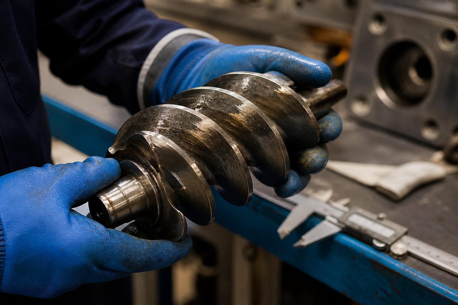
Troubleshooting Common Twin-Screw Extrusion Problems
Mechanical condition and parameter optimization set the stage for stable production — but even well-maintained twin-screw extruders encounter operational upsets. Output starts pulsating. Material oozes from the die lips. A torque alarm halts the line. These problems cost time, material, and money, yet they follow recognizable patterns. Once you learn to connect symptoms to root causes, most issues resolve in minutes rather than hours.
What follows is a practical diagnostic guide built from the most common failure modes encountered on production-floor and laboratory twin screw extruder platforms alike. Whether you are running a full-scale compounding line or developing formulations on a laboratory extruder, the underlying physics — and the corrective logic — are the same.
Surging, Die Drool, and Feed Inconsistencies
Output surging shows up as a rhythmic pulsation in extrudate flow rate. You will see it as fluctuating strand diameter, inconsistent pellet weight, or oscillating die pressure on the control panel. The causes fall into three categories:
- Feed inconsistency — Material bridging in the hopper, erratic feeder calibration, or rat-holing in low-bulk-density powders starves the screws intermittently. The fix starts upstream: install a hopper agitator, recalibrate the gravimetric feeder, or switch to a crammer feeder for difficult-flowing materials.
- Metering zone instability — If the screw profile lacks sufficient tight-pitch conveying elements near the die, pressure build-up becomes unsteady. Replacing the last two or three elements with a lower-pitch conveying design often stabilizes the discharge pressure immediately.
- Downstream restriction changes — A gradually fouling screen pack or partially blocked die holes increases backpressure unpredictably. Adam Dreiblatt of CPM Century Extrusion notes that as screen or die pressure increases, the backup length — the length of filled screw needed to develop the required pressure — extends accordingly, disrupting flow uniformity upstream. Increasing screen area or installing a continuous screen changer eliminates the progressive restriction.
Die drool — that annoying buildup of degraded material at the die lip — has different origins. Residual moisture flashing at the die exit deposits low-molecular-weight species on the lip surface. Volatile additives with boiling points near the melt temperature condense and accumulate. Corrective actions include improving upstream devolatilization (increase vacuum level or extend the venting zone), ensuring the material is adequately pre-dried, and polishing die land surfaces to reduce adhesion points.
Degradation, Poor Dispersion, and Vent Flow Issues
Discolored pellets, a burnt odor at the die, or reduced mechanical properties in finished parts all point toward thermal or thermo-mechanical degradation. The material has spent too long at too high a temperature — either from excessive barrel setpoints, too-aggressive kneading elements generating shear heat, or both. Industry troubleshooting guides consistently recommend checking the barrel temperature profile first, then evaluating whether the screw design introduces more shear than the formulation can tolerate. Reducing RPM, widening kneading block stagger angles, or removing a kneading element from the mixing zone can drop melt temperature several degrees — often enough to move back within the polymer's stability window.
Poor dispersion of fillers or pigments presents the opposite challenge: not enough mixing energy rather than too much. If you see specks, color streaks, or agglomerates in the extrudate, the kneading zone is failing to deliver adequate dispersive shear. Common culprits include kneading blocks positioned before the polymer is fully melted (so material bypasses them as unmelted solids), insufficient block length, or stagger angles that are too low for the agglomerate strength of the filler. Repositioning kneading elements downstream — after complete melting — and switching to narrower discs at higher stagger angles typically resolves the issue.
Vent flow — molten polymer escaping through vent ports — is one of the most frustrating problems on any screw plastic extruder. It disrupts degassing, contaminates the vent system, and often forces a line shutdown to clean the opening. Three root causes account for nearly every case:
- Overfilling — Feed rate exceeds the screw's conveying capacity in the vent zone, pushing melt up into the opening. Reduce feed rate or increase conveying element pitch in the vent section.
- Insufficient upstream melt seal — The reverse or restrictive elements upstream of the vent are not generating enough backpressure to keep melt contained. Dreiblatt explains that if melt flows from the vent only when vacuum is applied, the sealing elements are failing to resist the vacuum pressure — a condition solved only by reconfiguring the screw to use more restrictive seal elements.
- Downstream blockage — A fouling screen or frozen die holes extend the backup length until it reaches the vent opening. The melt will flow continuously even without vacuum applied. Solutions include decreasing downstream pressure, adding barrel length after the vent, or installing a melt pump to handle pressurization independently.
Torque Overload and Mechanical Issues
Torque overload occurs when the gearbox reaches its maximum rated capacity and the machine trips to protect the drive train. Four scenarios trigger this alarm most frequently on twin-screw extruders:
- Cold starts — Starting the screws before the barrel has reached operating temperature forces them to push against solid, unmelted material. Always allow barrels to reach setpoint and soak for the recommended time before initiating screw rotation.
- Over-feeding — Feeding material faster than the screws can convey and melt it fills the barrel beyond capacity, spiking torque. Reduce feed rate incrementally until torque stabilizes below 85% of maximum.
- Excessively high viscosity — Low-MFI resins or cold-feed materials demand more mechanical energy than the gearbox can deliver. Raising barrel temperatures in the melting zone or pre-heating the feedstock reduces melt viscosity and frees torque headroom.
- Overly restrictive screw configuration — Too many reverse elements or high-stagger kneading blocks create more resistance than the drive can overcome. Removing one or two kneading discs from the most restrictive zone often resolves chronic torque limits without significantly affecting mixing quality.
Whether your operation runs a high-volume production line or a small-diameter research platform from a specialized twin-screw extruder manufacturer, systematic diagnosis is always faster than guesswork. The table below consolidates the most common problems into a quick-reference format you can keep near the control panel:
| Problem | Common Causes | Diagnostic Signs | Corrective Actions |
|---|---|---|---|
| Output Surging | Feeder inconsistency; hopper bridging; insufficient metering pressure; screen fouling | Pulsating strand diameter; oscillating die pressure; fluctuating pellet weight | Recalibrate feeder; install hopper agitator; add tight-pitch metering elements; increase screen area or use continuous screen changer |
| Die Drool | Residual moisture; volatile additives; low-MW species migrating to die surface | Material buildup at die lip; discolored deposits; periodic contamination of extrudate surface | Improve upstream devolatilization; increase vacuum level; pre-dry feedstock; polish die land surfaces |
| Thermal Degradation | Excessive barrel temperature; overly aggressive kneading elements; prolonged residence time | Discolored pellets; burnt odor; reduced mechanical properties; elevated melt temperature above setpoint | Lower barrel setpoints in overheated zones; reduce RPM; replace high-stagger kneading blocks with gentler elements; increase throughput to shorten residence time |
| Poor Filler or Pigment Dispersion | Kneading elements placed before complete melting; insufficient block length or stagger angle; inadequate shear energy | Visible specks or agglomerates; color streaks; inconsistent mechanical properties across samples | Reposition kneading blocks after full melting zone; use narrower discs at 60 degree-90 degree stagger; increase RPM to raise shear rate |
| Vent Flow | Overfilling in vent zone; weak upstream melt seal; downstream backpressure extending backup length to vent | Melt or raw material exiting vent ports; loss of vacuum level; porous pellets from failed degassing | Reduce feed rate; install more restrictive seal elements upstream; decrease downstream pressure; add barrel length after vent or install melt pump |
| Torque Overload | Cold start; over-feeding; high-viscosity resin; overly restrictive screw profile | Torque alarm or machine trip; torque reading at or near 100%; motor current spike | Ensure full barrel heat soak before starting; reduce feed rate; raise melt-zone temperatures; remove restrictive kneading elements from screw profile |
| Screw or Barrel Wear | Abrasive fillers; corrosive additives; metal-to-metal contact from misalignment | Gradual throughput decline; rising melt temperature at constant conditions; increased torque; visible scoring on screw flights | Inspect and measure flight clearances; replace worn screw elements and barrel segments as matched sets; upgrade to wear-resistant metallurgy |
Every entry in this table traces back to principles covered earlier in this article — screw element function, barrel wear mechanics, parameter interactions, and the physics of conveying and mixing. Troubleshooting is not a separate skill from process design; it is the same knowledge applied in reverse. Instead of asking "what should happen," you ask "what went wrong" — and the answer almost always lives in the gap between the intended screw profile, the actual barrel condition, and the real operating parameters at the moment the problem appeared.
Frequently Asked Questions About Twin-Screw Extruders
1. What is the difference between a co-rotating and counter-rotating twin-screw extruder?
A co-rotating twin-screw extruder has both screws turning in the same direction with fully intermeshing, self-wiping profiles. This generates intense distributive and dispersive mixing, minimal dead zones, and narrow residence time distribution — making it ideal for compounding, reactive extrusion, and pharmaceutical processing. A counter-rotating design features screws turning in opposite directions, creating a gentle calendering action with lower shear stress. Counter-rotating machines, including conical variants, are preferred for heat-sensitive materials like rigid PVC and for profile or pipe extrusion where forming pressure matters more than mixing intensity.
2. How do I know when to replace my twin-screw extruder barrel or screw elements?
Key warning signs include reduced throughput at the same screw speed, elevated discharge melt temperature without parameter changes, rising torque percentage under constant conditions, visible scoring on screw flights during inspection, and growing product quality issues like gel specks or color inconsistency. These symptoms indicate that the clearance between screw flight tips and barrel bore has increased beyond acceptable limits. For critical applications, replacement should be considered when flight clearance reaches twice the original specification. Suppliers like NANHAIYA offer custom parallel twin screw barrels engineered with bimetallic or wear-resistant liners to extend service life in abrasive compounding and recycling environments.
3. What does L/D ratio mean on a twin-screw extruder specification sheet?
L/D ratio is the total barrel length divided by the screw diameter. It indicates how much processing length is available for melting, mixing, venting, and pressurization. A 32:1 ratio suits basic compounding with a single vent, while 48:1 to 52:1 ratios support multiple mixing stages, sequential venting, and downstream side feeding. Specialty configurations for reactive extrusion or multi-stage devolatilization can reach 60:1 or even 68:1. A longer L/D ratio does not automatically mean better performance — it means more flexibility to add process zones, which only matters if the application requires them.
4. Why do twin-screw extruders use modular screw elements instead of a single-piece screw?
Modular screw elements allow engineers to customize the processing profile for each specific formulation by arranging conveying elements, kneading blocks, reverse elements, and specialized mixers along a common splined shaft. Changing a single element alters the shear intensity, fill level, or residence time in that zone. This means one machine frame can serve dozens of applications — from gentle blending of heat-sensitive bioplastics to aggressive dispersive mixing of pigment masterbatch — simply by rearranging elements, rather than purchasing separate dedicated equipment for each process.
5. Can a twin-screw extruder be used for plastic recycling?
Yes, co-rotating twin-screw extruders are widely used in plastic recycling operations. Their starve-fed design accommodates the variable bulk density of recycled flakes and regrind, while multi-stage vacuum venting removes moisture and volatile contaminants without requiring a separate pre-drying step. Melt filtration systems integrated at the barrel discharge remove particulate contaminants before pelletizing. However, heavily contaminated post-consumer streams may require a single-screw pre-extruder for initial melting and coarse filtration upstream of the twin-screw compounder, since metal fragments can damage the closely intermeshing screw elements.
Written by
Nanhaiya Technical Team
Zhoushan Nanhaiya Plastic Machinery Co., Ltd.
The Nanhaiya technical team supports screw and barrel manufacturing projects through application review, technical communication, custom manufacturing coordination, and production and quality control.
Discuss Your Application
Related Articles
More insights on screw barrel technology and plastics processing.

What Nobody Tells You About Screw Barrel For Plastic Machine Design
Oct 10, 2026
Learn how screw barrel for plastic machine design affects melt quality, throughput, and wear life. Covers geometry, resin matching, troubleshooting, and sourcing.
Read Article
Single Screw Extruder for Sheet: Stop Guessing, Start Specifying
Oct 9, 2026
Learn how to specify a single screw extruder for sheet production. Covers screw geometry, resin-specific processing, troubleshooting, and maintenance best practices.
Read Article
PE Pipe Extruder Machine: What Datasheets Won't Tell You
Oct 9, 2026
Learn how a PE pipe extruder machine works, key specs explained, material grade selection, maintenance tips, and buyer guidance beyond the datasheet.
Read ArticleLooking for something else?
Search by material, symptom or product and jump straight to the relevant page.
These are navigation suggestions based on keyword matching — not a quotation, not a delivery commitment, and not a substitute for engineering review. Final specification is confirmed by our engineers against your drawings and processed material.
Need help with screw barrel selection?
Share your machine model, processed material and application. Our team can help with pricing and technical support.