

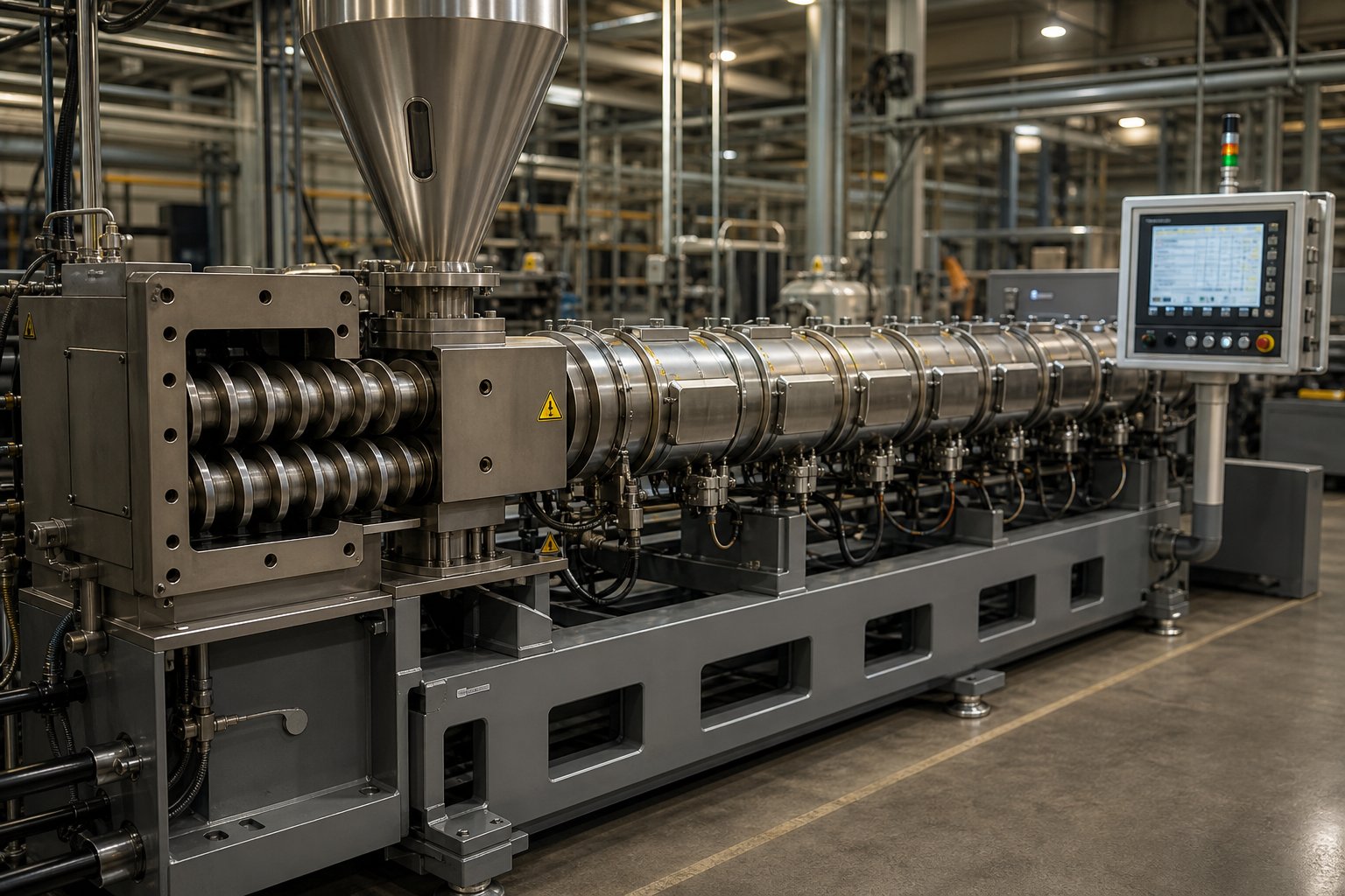
What Makes the Twin Screw Plastic Extruder Essential in Modern Processing
When you're evaluating extrusion equipment for a compounding line, a recycling operation, or a masterbatch facility, one question surfaces fast: why do nearly all high-performance plastic processing operations rely on twin screw technology instead of single screw systems? The answer lies in the fundamental mechanics of how these machines handle polymer materials, and understanding that difference is the first step toward making a smarter equipment decision.
This article is not a surface-level overview. It's built for plastics engineers tuning screw configurations, process technicians troubleshooting melt quality, and purchasing managers comparing twin screw extruder options across suppliers. Every section that follows dives into the technical depth these roles demand, from L/D ratio selection and screw element sequencing to total cost of ownership and wear part economics.
What Is a Twin Screw Plastic Extruder
A twin screw plastic extruder is a polymer processing machine that uses two co-rotating or counter-rotating intermeshing screws inside a segmented, heated barrel to convey, melt, mix, degas, and pressurize thermoplastic materials through a series of precisely controlled functional zones including feeding, plasticating, distributive mixing, venting, and metering.
That definition separates this machine from its single screw counterpart in several important ways. A single screw extruder relies on one rotating screw that depends heavily on frictional drag against the barrel wall to move material forward. Twin screw extrusion, by contrast, uses the intermeshing geometry of two screws to positively convey material regardless of friction characteristics. Imagine trying to push thick honey through a tube with one paddle versus two interlocking paddles working together. The twin-screw extruder doesn't just push material; it actively grabs, compresses, shears, and redistributes it at every turn.
The barrel itself is segmented into individually heated and cooled zones, each controlled independently. This modular barrel design, paired with interchangeable screw elements, gives operators the ability to configure the machine for vastly different polymer systems without purchasing entirely new equipment. It's a level of process flexibility that single screw machines simply cannot match.
Why Twin Screw Extruders Dominate Plastic Processing
Several core engineering advantages explain why the twin screw extruder has become the standard for demanding plastic processing tasks:
- Superior distributive and dispersive mixing: The intermeshing screw geometry creates complex flow patterns that break down additive agglomerates and distribute them uniformly throughout the polymer matrix, a critical requirement for filled compounds and color concentrates.
- Self-wiping capability: In co-rotating designs, one screw continuously wipes the surface of the other, preventing material stagnation, reducing degradation risk, and enabling faster material changeovers.
- Modular screw and barrel design: Engineers can rearrange conveying elements, kneading blocks, and mixing elements along the screw shaft to tailor the process to each specific resin and additive system.
- Better feeding of difficult materials: Low-bulk-density powders, fibers, and sticky additives that would starve or bridge in a single screw extruder feed reliably into the positive-conveying twin screw channel.
- Tighter process control: Independent control of screw speed, feed rate, barrel zone temperatures, and vacuum levels allows operators to fine-tune residence time, shear input, and melt temperature with a precision that directly impacts product quality.
These aren't theoretical benefits. They translate directly into narrower product tolerances, higher throughput with less thermal degradation, and the ability to process everything from commodity polyolefins to heat-sensitive engineering resins on the same platform. The versatility of twin screw extrusion is precisely why this technology appears in compounding plants, masterbatch facilities, reactive processing lines, and increasingly in plastic recycling operations worldwide.
Yet despite this dominance, critical details about how to configure, operate, and evaluate these machines remain poorly documented outside proprietary manufacturer training programs. The sections ahead unpack those details, starting with the most fundamental configuration decision any buyer or engineer faces: choosing between co-rotating and counter-rotating screw arrangements.
Co-Rotating vs Counter-Rotating Twin Screw Configurations Compared
Every twin screw plastic extruder falls into one of two fundamental categories based on a single mechanical fact: which direction do the screws turn? This choice, co-rotating or counter-rotating, dictates the shear profile, mixing intensity, pressure generation capability, and ultimately the range of polymers and end products the machine can handle. It's not a minor specification buried in a datasheet. It's the defining design decision that shapes everything downstream.
Yet most buyers and even some process engineers treat it as a checkbox rather than a design philosophy. Here's what actually separates these two configurations, and why picking the wrong one can cost you years of compromised output.
Co-Rotating Intermeshing Twin Screw Extruders
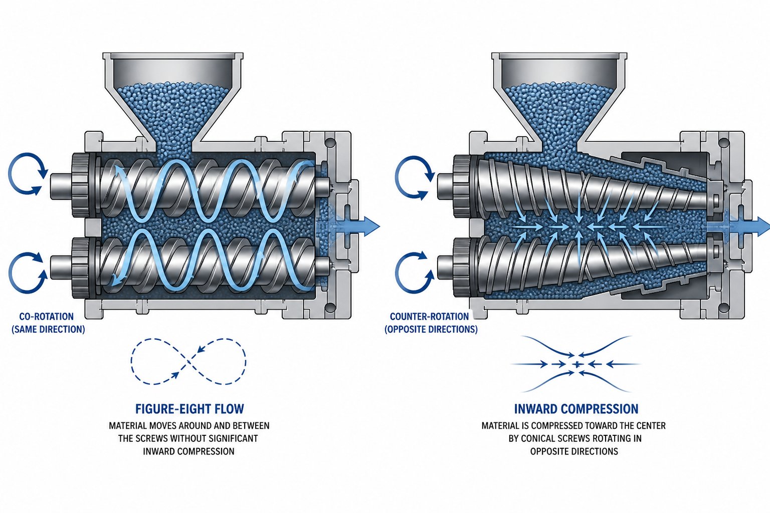
In a co-rotating twin screw extruder, both screws rotate in the same direction, typically with a fully intermeshing geometry. Picture two gears spinning the same way: material caught between them gets forcibly handed off from one screw flight to the next in a figure-eight flow pattern. This constant transfer creates intense shear fields both between the screws and between each screw and the barrel wall.
The practical result? Exceptional mixing performance. The co-rotating design produces both dispersive mixing (breaking down agglomerates into fine particles) and distributive mixing (spreading those particles evenly throughout the melt). Kneading blocks and other specialized elements add elongational flow components to the mix, imposing a complex deformation history on the polymer that single screw machines simply cannot replicate.
You'll also notice a critical self-wiping behavior. Because the screws intermesh tightly, one screw continuously scrapes material off the surface of the other. This eliminates dead zones, keeps the residence time distribution narrow, and makes product changeovers significantly faster. For reactive extrusion processes or thermally sensitive formulations where even small pockets of stagnant material can cause degradation, self-wiping is not just convenient; it's essential.
The parallel co-rotating twin screw extruder is the industry standard for the vast majority of plastic compounding tasks. Its modular screw and barrel design allows engineers to rearrange conveying elements, kneading blocks, and mixing discs along the shaft to match nearly any polymer and additive system. Typical applications include compounding with inorganic and organic fillers, polymer alloy production, masterbatch manufacturing, reactive extrusion for grafting or compatibilization, and increasingly, plastic recycling lines processing contaminated post-consumer feedstocks. Screw speeds on production machines commonly range from 400 to 900 rpm, with some high-speed designs exceeding 1,200 rpm.
Counter-Rotating Twin Screw Extruders
Flip one screw's rotation and the entire processing character changes. In a counter-rotating twin screw extruder, the screws rotate in opposite directions. At the intermeshing region, material is drawn inward and compressed rather than transferred laterally. Transport depends more directly on screw rotation itself, and the machine operates under a high degree of fill as a fundamental premise.
The mixing mechanism here is fundamentally different from the co-rotating approach. Instead of high-shear dispersive action, counter-rotating designs rely primarily on compressive and elongational deformation. A calendering effect develops at the intermeshing zone, similar to what happens between calender rolls: material passes through and undergoes repeated compression and stretching under relatively gentle conditions. Shear stress and the associated shear-induced heating stay low, making this configuration ideal for polymers that degrade rapidly under thermal stress.
Counter-rotating machines come in two distinct geometries: parallel and conical. A parallel twin screw extruder maintains constant screw diameter along the entire barrel length, offering longer processing zones and greater design flexibility for venting and feeding. A conical twin screw extruder, by contrast, features screws that taper from a large diameter at the feed end to a smaller diameter at the discharge. This tapering geometry naturally compresses material as it advances, generating substantial die pressure without requiring high screw speeds. The conical design also allows wider center-to-center screw spacing at the feed section, which accommodates larger gearboxes and delivers higher operating torque.
Rigid PVC is the signature application for counter-rotating technology. PVC's low thermal decomposition temperature and poor melt-flow characteristics make it a poor candidate for the high-shear environment inside a co-rotating machine. The counter-rotating configuration holds extrusion temperatures low through operation at high fill and low rotational speed, typically 30 to 150 rpm. This gentle processing profile enables stable production of PVC pipes, window profiles, door frames, and sheet products without triggering degradation. Beyond PVC, counter-rotating extruders handle wood-plastic composites, highly filled mineral compounds, and other thermally sensitive formulations where controlled, low-shear conveying takes priority over aggressive mixing.
Side-by-Side Configuration Comparison
Choosing between co-rotating and counter-rotating configurations often feels abstract until you see the key attributes mapped against each other. The table below provides a direct comparison that covers the parameters most relevant to selecting the right double screw extruder for your process. Whether you're evaluating a co-rotating and counter-rotating twin screw extruder side by side for a new compounding project or reviewing specifications for a PVC pipe line, these distinctions will sharpen your decision.
| Attribute | Co-Rotating Intermeshing | Counter-Rotating Intermeshing |
|---|---|---|
| Rotation Direction | Both screws rotate in the same direction | Screws rotate in opposite directions |
| Intermeshing Type | Fully intermeshing (standard) | Fully or partially intermeshing |
| Self-Wiping Behavior | Excellent; continuous mutual wiping eliminates dead zones | Moderate; lower speeds and geometry can leave minor stagnant zones |
| Shear Intensity | High; strong shear fields between screws and between screw and barrel | Low to moderate; calendering effect with gentle compressive deformation |
| Mixing Quality | Superior distributive and dispersive mixing; complex deformation history | Good distributive mixing via calendering; limited dispersive capability |
| Pressure Generation | Moderate; typically requires gear pump for high-pressure die applications | High; conical taper naturally compresses melt for excellent die pressure |
| Screw Geometry | Parallel (standard) | Parallel or conical |
| Typical Screw Speed | 400 - 900+ rpm | 30 - 150 rpm (conical); up to 300 rpm (parallel) |
| Typical Plastic Applications | Polyolefin compounding, engineering resins, masterbatch, recycling, reactive extrusion | Rigid PVC, wood-plastic composites, highly filled mineral compounds, thermally sensitive formulations |
| Throughput Range | High; suited for large-scale production compounding | Low to moderate; optimized for controlled, steady-rate extrusion |
| Common End Products | Compounded pellets, masterbatch granules, recycled pellets, reactive blends | PVC pipes, window profiles, door frames, WPC decking, PVC sheet |
Notice how the differences aren't subtle. A co-rotating machine and a counter-rotating machine are engineered for fundamentally different processing philosophies: one prioritizes intense mixing and throughput, the other prioritizes gentle conveying and pressure buildup. Selecting the wrong configuration doesn't just reduce efficiency; it can make certain polymers entirely unprocessable.
Configuration choice, however, is only the starting point. The real performance of any twin screw extruder depends on how you set the operating parameters within that configuration, and several of those parameters are poorly understood even by experienced operators.
Critical Operating Parameters Every Operator Must Understand
Selecting the right screw configuration gets you to the starting line. Crossing it, consistently producing high-quality output at target throughput, depends on how precisely you control a handful of interdependent process variables. These are the parameters that separate a well-run twin screw extrusion process from one plagued by surging, degradation, or inconsistent pellet quality. Surprisingly, most manufacturer documentation glosses over these details, leaving operators to learn through trial and error.
L/D Ratio and Its Impact on Plastic Processing
The length-to-diameter ratio, universally abbreviated as L/D, is the ratio of the barrel's effective processing length to the screw diameter. A machine with 60 mm screws and a 2,400 mm processing length has a 40:1 L/D ratio. Sounds like a simple geometric spec, right? In practice, it determines how much processing work the extruder can perform on the material before it exits the die.
A longer L/D ratio, typically in the 40:1 to 52:1 range, provides more barrel zones for melting, mixing, and venting. That extended residence time is essential when you're running complex compounding tasks: reactive extrusion requiring long reaction times, deep degassing of engineering resins carrying residual moisture or monomers, or multi-stage addition of fillers and fibers through side feeders. Some specialized co-rotating machines push L/D ratios as high as 68:1 for demanding devolatilization or tandem extrusion setups.
Shorter L/D ratios, around 24:1 to 32:1, suit simpler processes: basic blending of pre-compounded materials, direct extrusion of profiles, or applications where minimizing residence time protects thermally sensitive polymers. Rigid PVC processing on counter-rotating machines, for example, typically uses shorter barrels to limit heat exposure and prevent degradation.
Here's where many buyers go wrong: they default to the longest L/D available, assuming more is always better. It isn't. As industry analysis confirms, excessive L/D ratios increase power consumption, raise manufacturing complexity, and introduce structural risks such as shaft deflection that can cause barrel wall scoring. The right L/D ratio is determined by the polymer system, the number of unit operations required (feeding, melting, mixing, venting, metering), and the desired throughput rate, not by a bigger-is-better mentality.
Screw Speed, Torque, and Temperature Profile Fundamentals
If L/D ratio defines how much processing space you have, screw speed determines how aggressively you use it. Co-rotating twin screw extruders commonly operate between 300 and 900 rpm for production compounding, with high-performance machines reaching 1,200 rpm. Increasing screw speed raises throughput in a nearly linear relationship, but it also amplifies shear heating inside the melt. Push the speed too high without adjusting feed rate or barrel cooling, and melt temperature climbs beyond acceptable limits, triggering polymer degradation, discoloration, or off-gassing.
This is where the concept of specific torque density becomes critical. Expressed in Newton-meters per cubic centimeter (Nm/cm³), torque density measures the gearbox's ability to transmit rotational force through the screw shafts relative to the available processing volume. Modern state-of-the-art designs achieve torque densities around 18 Nm/cm³, roughly 30% higher than older platforms. Why does this matter? When you're processing high-viscosity engineering resins like PA66 or PC, or running heavily filled systems with 60% or more mineral content, the motor must deliver enough torque to keep the screws turning against tremendous resistance. An undersized drive doesn't just limit throughput; it risks gearbox failure. A practical sizing formula helps illustrate the relationship:
Torque (Nm) = 9,550 x Power (kW) / Screw Speed (RPM). A 200 kW motor at 500 rpm delivers approximately 3,820 Nm per shaft.
Always select a motor providing at least 20% more torque than the peak process demand. Running continuously above 80% of rated torque accelerates gearbox wear and invites catastrophic failure during cold starts or high-filler-loading conditions.
Temperature profiles across the barrel zones are equally consequential. A typical twin screw plastic extruder barrel is segmented into 6 to 12 independently controlled zones, each with its own heating elements and cooling channels. These zones progress through distinct functional stages: a relatively cool feed zone (often 40 to 80 degrees Celsius to prevent premature melting and bridging), rising temperatures through the melting and plasticating zone, peak temperatures in the mixing zone where polymer viscosity must be low enough for effective dispersion, reduced temperatures at the venting zone to lower vapor pressure and facilitate volatile extraction, and a stabilized metering zone that conditions the melt for consistent die discharge. Independent zone control, maintaining setpoints within plus or minus 2 degrees Celsius, is not optional for precision screw extrusion. It's the difference between uniform melt quality and the kind of temperature excursions that cause barrel-to-barrel variation in pellet color, mechanical properties, or surface finish.
Every operator should understand and actively monitor these key parameters:
- Screw speed (rpm): Controls throughput and shear intensity; must be balanced against melt temperature limits
- Specific energy input (kWh/kg): The total mechanical and thermal energy delivered per kilogram of material; a primary indicator of process efficiency and melt quality
- Barrel zone temperatures: Set independently across feeding, melting, mixing, venting, and metering zones to match each stage's functional requirements
- Feed rate (kg/h): The mass flow of material entering the extruder; directly impacts degree of fill, residence time, and mixing intensity
- Die pressure (bar): Backpressure at the extruder discharge; affects melt homogeneity and must be stable to ensure consistent pellet or profile dimensions
One of the most misunderstood operating decisions ties directly to feed rate: whether to run starve-fed or flood-fed. In starve-fed operation, the gravimetric feeder meters material into the barrel at a rate lower than the screw's maximum conveying capacity. The plastic extruder screw channels remain only partially filled, which gives operators independent control over both feed rate and screw speed. This is the standard approach for co-rotating compounding extruders because it decouples throughput from screw speed, allowing you to optimize mixing intensity and residence time separately. The degree of fill in the screw channels directly influences how much shear and energy the material experiences in kneading zones.
Flood-fed operation, by contrast, fills the screw channels completely. The feed hopper sits directly above the barrel opening, and material enters by gravity as fast as the screw can accept it. Throughput is then dictated entirely by screw speed. Counter-rotating extruders for PVC pipe and profile extrusion commonly use this method because the process demands a consistently full channel for stable pressure generation. The tradeoff is less independent control over mixing intensity.
Getting these parameters right isn't a one-time calibration exercise. Polymer batches vary, ambient temperatures shift, and wear on screw elements gradually changes the shear profile. The operators who produce the most consistent output are the ones who understand not just what each parameter does in isolation, but how changing one ripples through the others.
That interconnected reality raises a natural follow-up question: how are the physical screw elements themselves arranged to create the distinct functional zones where all of these parameters actually do their work?
How to Configure Twin Screw Elements for Plastic Processing
Every extruder screw you see on a twin screw machine is not a single monolithic shaft. It's a carefully assembled stack of individual elements, each shaped for a specific job, slid onto a splined shaft in a deliberate sequence. Change the order, swap one kneading block for a conveying element, or adjust a stagger angle by 30 degrees, and the entire melt behavior shifts. This modularity is what makes twin screw technology so powerful, and so unforgiving when configured incorrectly.
Think of it like building a pipeline where each section transforms the material passing through it. The sequence matters as much as the individual parts. A kneading block placed too early starves the melt zone. A conveying element with the wrong pitch in the venting section traps volatiles instead of releasing them. Understanding what each zone does, and which elements belong there, is knowledge that separates competent operators from those constantly chasing quality problems.
Functional Zones Along the Twin Screw
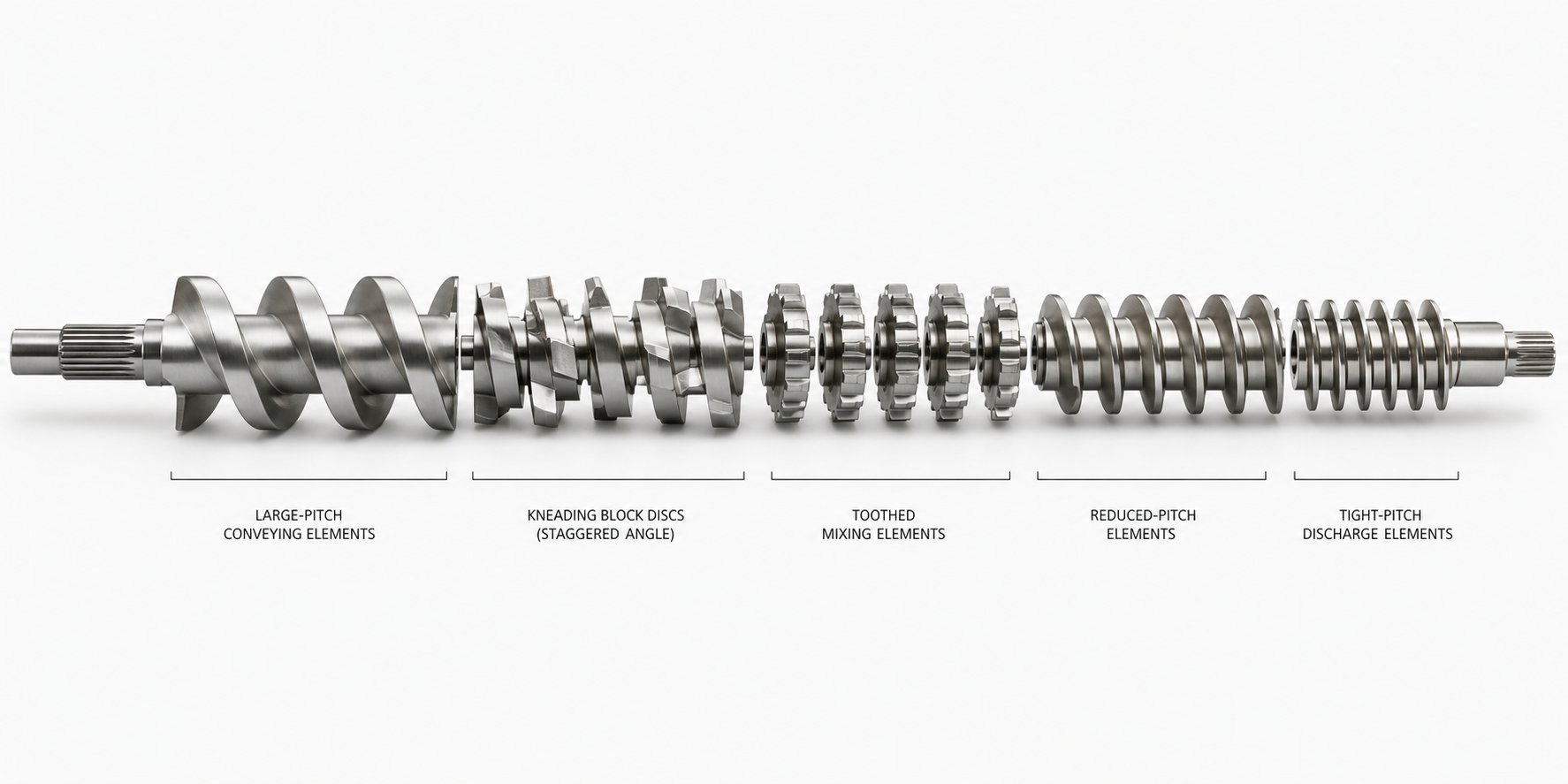
A typical twin screw and barrel assembly is organized into five distinct functional zones, each performing a specific transformation on the material as it moves from hopper to die. Here's what happens in each zone, and which screw elements make it possible:
- Solids conveying zone: This is where raw material enters the barrel through the feed throat. Large-pitch conveying elements with deep flights grab pellets, powders, or flakes and push them forward rapidly. The goal here is simple: move material downstream quickly without compressing it prematurely. Large-pitch elements prioritize throughput, reduce residence time, and minimize degradation risk in the feed section. Some configurations use undercut conveying elements with reduced flight depth to gently pre-compress the solids bed before it reaches the melting zone. Barrel temperatures here stay low, often 40 to 80 degrees Celsius, to prevent premature softening that could cause bridging in the feed throat.
- Melting and plasticating zone: This is where the real transformation begins. Kneading blocks, arranged in a forward-staggering pattern, replace the conveying elements. These disc-shaped elements are set at offset angles, commonly 30, 45, 60, or 90 degrees, and they impose intense shear on the material as it passes between the rotating discs and the barrel wall. Wider-pitch kneading blocks exert stronger dispersive shear, while narrower configurations promote better material distribution through side overflow during compression. Reverse-thread elements or neutral (90-degree) kneading blocks are often placed at the end of this zone to create a "melt seal," a fully filled section that prevents unmelted solids from advancing and ensures complete plasticating before the material enters the mixing zone.
- Distributive and dispersive mixing zone: Once the polymer is fully molten, specialized mixing elements take over. These can include toothed mixing elements, ZME-type (zig-zag mixing elements), or additional kneading blocks configured specifically for blending rather than melting. The objective shifts from phase change to homogeneity: breaking down filler agglomerates, distributing pigment particles uniformly, or incorporating additives into the polymer matrix at the molecular level. Distributive mixing splits and recombines melt streams repeatedly, while dispersive mixing applies stress concentrations that fracture particle clusters. Your extruder screw and barrel configuration in this zone defines the final compound quality more than any other section of the machine.
- Venting and degassing zone: Immediately downstream of the mixing section, the screw design changes dramatically. Conveying elements with increased pitch and reduced flight depth create a partially filled channel, dropping the local pressure close to zero. This pressure relief allows trapped volatiles, moisture, air, and residual monomers, to escape through open ports in the twin screw barrel. The degree of fill in this zone must remain low; if the screw channels are too full, melt reaches the vent opening and blocks it, a problem so common that industry experts identify it as one of the most frequent operational issues on twin screw compounding lines. Upstream melt seals created by restrictive elements ensure that gases travel toward the vent port rather than back toward the feed zone.
- Pressure buildup and discharge zone: The final section of the extruder screw uses tight-pitch, narrow-channel conveying elements that progressively compress the degassed melt and build the pressure needed to force it through the die plate, strand die, or pelletizer head. Small-pitch threads that gradually decrease in size improve pressure buildup, melt quality, and extrusion stability. This zone also provides a final mixing action that helps homogenize any remaining temperature gradients in the melt. Consistent die pressure in this zone is essential for uniform pellet weight and dimensions.
Notice how the entire sequence follows a deliberate logic: grab, melt, mix, release, push. Each zone hands off material to the next in a specific state, and the transitions between zones are just as critical as the zones themselves. A melt seal that's too aggressive creates excessive shear heating. A venting zone that's too short doesn't allow enough residence time under low pressure for volatiles to diffuse out of the melt. Configuring a twin screw and barrel assembly is an exercise in balancing competing demands across every centimeter of processing length.
Atmospheric vs Vacuum Venting in Plastic Extrusion
Venting is the most underappreciated zone on any twin screw plastic extruder, yet it directly controls surface quality, mechanical properties, and dimensional stability of the final product. Bubbles, voids, splay marks, and poor surface finish on extruded or molded parts almost always trace back to inadequate degassing during compounding. Two distinct venting methods exist, and understanding when to deploy each one prevents costly quality failures.
Atmospheric venting uses open barrel ports that allow gases to escape to the surrounding environment at ambient pressure. When polymer pellets enter the barrel, they carry entrained air between particles. As the material melts and compresses, that trapped air must go somewhere. Atmospheric vents positioned after the initial melting zone provide the escape path. They also play a critical role when side feeders introduce low-bulk-density fillers like talc or calcium carbonate downstream. These powdery additives bring enormous volumes of interstitial air into the barrel, and without adequate atmospheric venting, that air causes backflow, filler blow-out, and erratic feeding. As process technology experts note, the lower the bulk density of the filler, the more air enters the extruder and must be vented, sometimes requiring multiple atmospheric vent ports along the barrel.
Vacuum venting takes degassing far deeper. Sealed barrel ports connect to vacuum pumps that pull the local pressure down to approximately 100 to 300 mbar (20 to 27 inches of mercury). This aggressive pressure reduction dramatically lowers the boiling point of trapped moisture, residual monomers, and dissolved volatile compounds, forcing them out of the melt. Vacuum venting is essential when processing hygroscopic engineering resins like polyamide or polycarbonate, where residual moisture causes hydrolytic degradation and molecular weight loss. It's equally critical for recycled plastic feedstocks, which often carry residual printing inks, adhesives, food contaminants, and degradation byproducts that atmospheric venting alone cannot extract.
Most production twin screw compounding extruders combine both methods: one or more atmospheric vents near the feed and side-feeder zones, plus at least one vacuum vent positioned closer to the discharge end after the final mixing section. Some machines designed for deep devolatilization run two or even three vacuum vents in series, extending the barrel length to accommodate them.
Proper venting demands more than just drilling holes in the barrel. The screw configuration beneath each vent port must maintain a low degree of fill so melt doesn't rise into the opening. If backup length, the filled screw section needed to generate die pressure, grows long enough to reach the vacuum port, melt floods the vent and shuts down the degassing function entirely. Worn pumping elements near the discharge gradually worsen this problem over time, making it a chronic condition rather than a one-time event. In extreme cases, specialty materials that foam or expand under vacuum require mechanical vent stuffers, twin-screw devices mounted in the vent opening that physically prevent melt from escaping while still allowing gas extraction.
Getting the venting configuration right is half the battle. The other half is matching your overall screw design and operating parameters to the specific polymer you're processing, because different plastics impose radically different demands on every zone described above.
Which Plastics Are Processed on Twin Screw Extruders
Every screw element, barrel zone temperature, and venting strategy discussed so far exists to serve one purpose: transforming a specific polymer system into a consistent, high-quality output. Yet here's what most equipment guides get wrong. They describe the machine in isolation, listing features without connecting them to the real-world materials that demand those features. A kneading block stagger angle means nothing until you understand why PVC requires a completely different approach than polyamide, or why running a 70% calcium carbonate masterbatch through the wrong screw geometry guarantees filler agglomerates in your final pellets.
Each polymer family imposes a distinct set of thermal, rheological, and chemical constraints on the twin screw compounding extruder. The machine configuration must adapt to those constraints, not the other way around. Let's walk through the major polymer families and the specific extruder setups they demand.
Commodity and Engineering Plastics on Twin Screw Extruders
PVC: The polymer that rewrote the rules. Polyvinyl chloride stands apart from virtually every other thermoplastic because its processing window is dangerously narrow. PVC begins degrading at temperatures only slightly above its fusion point, releasing hydrochloric acid gas that corrodes equipment and contaminates product. This thermal sensitivity is precisely why counter-rotating twin screw extruders dominate PVC processing. As Bausano's technical analysis confirms, fully intermeshing counter-rotating machines function as positive displacement pumps independent of frictional criteria, making them purpose-built for thermally sensitive polymers like PVC and C-PVC.
For standard rigid PVC pipe and profile extrusion, conical counter-rotating extruders remain the classic choice. Their tapering screw geometry generates high die pressure at low rotational speeds, typically 15 to 40 rpm, keeping shear heating minimal. But the conical design isn't always optimal. When you're processing PVC with high filler loads, say 100 phr of calcium carbonate, a parallel counter-rotating twin screw extruder becomes the better solution. Why? The parallel screw's longer L/D ratio, around 30:1, provides more time for the plasticization process, allowing thorough coating and amalgamation of the carbonate filler. The parallel screw's larger core diameter also resists the corrosive action of calcium carbonate more effectively, extending barrel and screw element life compared to conical alternatives.
Polyolefins: The workhorse compounds. Polyethylene and polypropylene compounding runs almost exclusively on co-rotating parallel twin screw extruders. These resins process at moderate temperatures, between 180 and 250 degrees Celsius depending on grade and filler system, and tolerate the high shear that co-rotating machines generate. You'll find a plastic twin screw extruder running PE or PP compounds in nearly every compounding plant worldwide, blending these base resins with mineral fillers, UV stabilizers, antioxidants, flame retardants, or pigment concentrates. Screw speeds typically range from 400 to 800 rpm, and L/D ratios of 40:1 to 48:1 provide adequate residence time for mixing and degassing. The real challenge with polyolefins isn't thermal sensitivity; it's achieving uniform dispersion of additives and fillers at high throughput rates without creating agglomerates or undispersed particles.
Engineering resins: Higher demands across the board. Polyamide (PA), polybutylene terephthalate (PBT), polycarbonate (PC), and their blends represent the most demanding category for any polymer extruder. These resins process at elevated temperatures, often 260 to 320 degrees Celsius, and many are hygroscopic, absorbing atmospheric moisture that causes hydrolytic degradation during processing. Running PA6 or PA66 without deep vacuum venting, typically at 50 to 100 mbar absolute, guarantees molecular weight loss and compromised mechanical performance in the finished compound.
Higher processing temperatures also mean higher melt viscosities at the feed and melting zones, which translates directly into greater torque demand on the gearbox. An extruder for polymer systems like glass-fiber-reinforced PA66 needs a high torque density drive, modern machines targeting 13 to 18 Nm/cm³, to maintain stable screw speed under the intense resistance these materials create. Temperature profiles must be tightly controlled across all barrel zones, with precise cooling in the venting sections to reduce vapor pressure and maximize volatile extraction efficiency. Even small deviations, a zone running 10 degrees above setpoint, can shift the melt viscosity enough to disrupt fill levels in the venting zone and trigger vent flooding.
Specialty Compounds and Filled Systems
Beyond the major resin families, a significant share of twin screw extrusion capacity serves specialty applications where the additive or filler system drives equipment selection as much as the base polymer does.
Thermoplastic elastomers (TPE/TPU) require careful balancing of shear and temperature to preserve their elastomeric phase morphology. Excessive dispersive mixing can destroy the rubber domains that give TPE its flexibility, while insufficient mixing leaves the hard and soft phases poorly blended. Screw configurations for TPE typically use moderate kneading blocks followed by distributive mixing elements like toothed or gear-type discs that blend without imposing excessive stress.
Highly filled compounds present a different set of challenges altogether. When talc, calcium carbonate, or glass fiber loading exceeds 40 to 60% by weight, the compound behaves less like a polymer melt and more like a viscous paste. As research published by Plastics Technology details, these systems require extruders with high free volume, controlled by the Do/Di ratio of the screw elements. A Do/Di ratio of 1.65 or higher is recommended, with some large free-volume machines reaching 1.80. Multiple side feeders introduce the filler in stages, and atmospheric back vents between each feeding point manage the enormous volume of entrained air that accompanies low-bulk-density powders. Barrel liners and screw elements in these applications must use wear-resistant metallurgy, bimetallic constructions with tungsten carbide or boron-based alloy coatings, because mineral fillers are brutally abrasive and can destroy standard nitrided steel components within months.
Color masterbatch and carbon black concentrates demand superior distributive mixing to achieve streak-free dispersion at high pigment loadings. These formulations typically run on co-rotating machines at L/D ratios of 40:1 to 48:1 with extended mixing zones featuring multiple kneading block sequences and toothed mixing elements. The challenge is less about thermal sensitivity and more about breaking apart pigment agglomerates into sub-micron particles and distributing them uniformly, a task where the figure-eight flow pattern of co-rotating screws excels.
The following list maps common polymer systems to their recommended extruder configurations and approximate L/D ratios, giving you a quick reference when evaluating equipment for a specific application:
- Rigid PVC pipe and profiles: Counter-rotating conical or parallel; L/D 20:1 to 30:1
- PE/PP filled compounds: Co-rotating parallel; L/D 40:1 to 48:1
- PA (glass-fiber-reinforced): Co-rotating parallel, high torque density; L/D 40:1 to 48:1 with vacuum venting
- PC and PC/ABS blends: Co-rotating parallel; L/D 36:1 to 44:1 with deep vacuum degassing
- PBT compounds: Co-rotating parallel; L/D 36:1 to 44:1 with vacuum venting and precise temperature control
- TPE/TPU: Co-rotating parallel with moderate shear screw design; L/D 32:1 to 40:1
- Highly filled mineral compounds (>50% filler): Co-rotating parallel, high free volume (Do/Di ≥ 1.65); L/D 40:1 to 48:1 with multiple side feeders
- Color masterbatch: Co-rotating parallel with extended mixing zones; L/D 40:1 to 48:1
- Carbon black concentrates: Co-rotating parallel, high free volume; L/D 40:1 to 48:1
- Wood-plastic composites (WPC): Counter-rotating parallel or conical; L/D 24:1 to 36:1
Barrel metallurgy adapts alongside screw design. Unfilled or lightly filled resins process comfortably through standard nitrided steel barrels. Glass-fiber-reinforced compounds demand bimetallic barrel liners with iron-boron alloy or tungsten carbide coatings that resist abrasive wear. Corrosive polymers like PVC and fluoropolymers require barrels with nickel-chromium-molybdenum alloy liners that resist chemical attack at elevated temperatures. Selecting the wrong barrel metallurgy doesn't just shorten replacement intervals; it introduces metal contaminants into the polymer melt that compromise product quality and can create visible defects in finished parts.
Matching the right machine to the right material is foundational. But a twin screw compounding extruder never operates alone. It sits at the center of an integrated processing line, and the equipment upstream and downstream determines whether all that carefully optimized polymer processing actually translates into consistent, saleable product.
Key Applications From Compounding to Plastic Recycling
Knowing which polymer runs on which configuration is valuable, but it doesn't answer the question that actually drives equipment purchases: what do you need the machine to accomplish? A compounding twin screw extruder producing glass-fiber-reinforced PA66 pellets for automotive connectors faces entirely different operational demands than the same machine architecture blending post-consumer HDPE flake into recycled pellets for agricultural film. The application, not just the material, shapes everything from screw element sequencing to downstream pelletizing strategy.
Let's shift from materials to missions and examine the core applications where twin screw extruders create the most value.
Compounding, Masterbatch, and Reactive Extrusion
Plastic compounding is the backbone application for co-rotating twin screw extruders, and it's more complex than most people assume. At its core, compounding is the blending of a base polymer resin with additives, fillers, pigments, flame retardants, impact modifiers, or reinforcing fibers to engineer a material that performs differently than the raw resin alone. Imagine polypropylene by itself: decent stiffness, modest heat resistance, limited UV stability. Run that same PP through a compounding extruder with 30% talc, a hindered amine light stabilizer, and a nucleating agent, and you've created an entirely different material suitable for automotive dashboard components or outdoor furniture.
The compounding extruder achieves this transformation through precise control of shear, temperature, and residence time across its functional zones. Fillers must be uniformly dispersed without being pulverized. Additives must be incorporated without thermal degradation. Fiber reinforcements must maintain their aspect ratio, the length-to-diameter relationship that determines their reinforcing effectiveness, despite the intense mechanical forces inside the barrel. Every screw configuration choice discussed earlier serves this goal: kneading block intensity determines dispersion quality, venting zones remove volatiles introduced by additives, and discharge elements build consistent pressure for pelletizing.
Masterbatch production is a specialized branch of compounding where concentrated carriers, typically containing 40 to 70% pigment, additive, or filler in a compatible polymer base, are manufactured for downstream processors. A color masterbatch producer might load 50% organic pigment into an LDPE carrier, requiring extended mixing zones to break apart pigment agglomerates into sub-micron particles and achieve streak-free dispersion. The downstream injection molder or film extruder then adds this concentrate at 2 to 5% letdown ratio into their base resin, achieving the target color without handling raw pigments directly. This business model depends entirely on the compounding twin screw extruder's ability to produce microscopic-level uniformity at high concentration levels.
Reactive extrusion pushes the machine's role even further. Here, the extruder functions not just as a mixer but as a continuous chemical reactor. Twin screw extruders play a key role in reactive extrusion because of their capability to achieve high levels of mixing and their ability to handle materials exhibiting high viscosity. Common reactive processes include maleic anhydride grafting onto polyolefin backbones to create coupling agents and compatibilizers, silane crosslinking of polyethylene for wire and cable insulation, and controlled rheology modification of polypropylene through peroxide-initiated chain scission. In each case, the extruder must precisely control temperature to activate initiators at the right moment, deliver enough mixing energy to ensure homogeneous distribution of reactive species within the melt, and provide sufficient residence time for the chemical reaction to reach target conversion levels. As reactive extrusion research demonstrates, the functionalization of polyolefins through this process widens their range of applications significantly, from impact modification of polyamides to compatibilization of multi-layer packaging structures.
Twin Screw Extruders in Plastic Recycling and Sustainability
Here's the application category that's reshaping the entire twin screw market, and the one most equipment guides still barely mention: mechanical recycling of post-consumer and post-industrial plastic waste.
The recycling challenge is fundamentally different from virgin compounding. When you process virgin pellets, you control the feedstock: uniform particle size, known moisture content, predictable melt flow index. Recycled feedstocks are the opposite. Post-consumer polyolefin film arrives as shredded flakes with wildly variable bulk density, fluctuating moisture levels, and contamination ranging from residual food waste and printing inks to adhesive residues and mixed polymer fractions. As industry reporting from Waste Management World documents, highly variable post-consumer polyolefin packaging, particularly film-rich streams, is causing the most engineering pain for extruder operators right now.
Twin screw extruders have become the consensus platform for demanding recycling applications precisely because their core strengths align with recycling's core challenges. Superior mixing homogenizes variable-quality melt streams. Modular screw profiles can be reconfigured when the incoming waste stream changes character. Multiple venting zones, both atmospheric and vacuum, extract moisture, trapped air, residual odors, and degradation byproducts that would compromise pellet quality on less capable machines. Coperion's development of specialized side feeders with conical twin-screw geometries addresses the notorious difficulty of getting low-bulk-density shredded film into the barrel at meaningful throughput rates, a problem that has historically limited recycling line productivity.
The scale argument is equally compelling. Industry experts identify a threshold at approximately one tonne per hour where the twin screw's advantage over single screw systems becomes decisive. Below that volume, simpler single screw recycling lines can deliver adequate quality. Above it, the twin screw's ability to simultaneously achieve excellent homogenization, effective degassing, and minimal product degradation without generating gels sets it apart. When major importing countries restricted plastic waste imports, suddenly much larger waste streams needed domestic processing, and twin screw extruders scaled to meet that demand.
The output from recycling lines typically takes one of two forms. Strand pelletizing, where extruded polymer strands are cooled in a water bath and cut into cylindrical pellets, remains the most common format for standard recycled compounds. Underwater pelletizing, where the melt is cut at the die face and immediately quenched, produces rounder pellets with more uniform geometry and is preferred for higher-throughput lines and applications where pellet shape affects downstream processing. A screw extruder granulator setup, combining the twin screw with an integrated pelletizing head, represents the most compact configuration for recycling facilities where floor space is at a premium.
Across all these applications, the common thread is versatility. The same fundamental machine platform, a co-rotating twin screw extruder with modular screws and segmented barrels, serves compounding plants, masterbatch producers, reactive processing facilities, and recycling operations. What changes is the configuration, not the architecture. Here's a consolidated view of the primary application categories where twin screw extruders deliver the most value:
- Filled compound production: Blending base resins with mineral fillers, glass fibers, and performance additives for automotive, construction, and consumer goods markets
- Color and additive masterbatch: Manufacturing concentrated pigment and additive carriers at high loading levels for letdown by downstream processors
- Direct profile and sheet extrusion: Processing compounds directly into finished or semi-finished shapes, particularly PVC pipes, profiles, and sheet on counter-rotating machines
- Plastic recycling and reclamation: Converting post-consumer and post-industrial waste streams into reusable pellets through melt filtration, degassing, and homogenization
- Reactive processing: Using the extruder as a continuous chemical reactor for grafting, crosslinking, controlled degradation, compatibilization, and polymerization
Each of these applications places different priorities on the machine's capabilities, but none of them operates in isolation. A compounding extruder without accurate feeding produces inconsistent batches. A recycling line without proper pelletizing wastes every kilogram of carefully processed melt. The equipment surrounding the extruder, both upstream and downstream, determines whether optimized processing actually translates into sellable product.
Building a Complete Twin Screw Extrusion Line
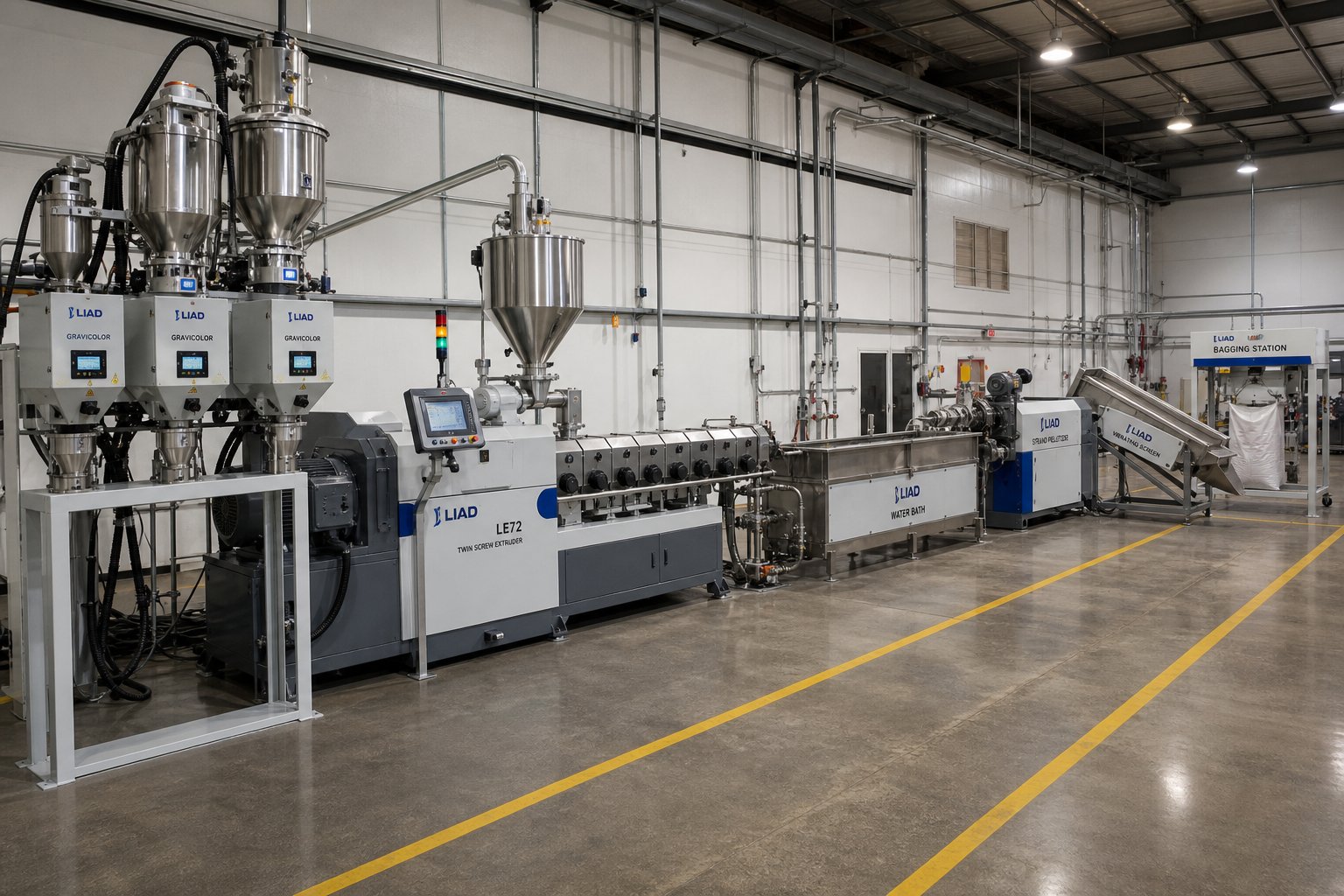
A twin screw extruder machine sitting on a factory floor by itself produces nothing. It's the centerpiece of a much larger extruder system, and every kilogram of quality compound or recycled pellet depends on how well the surrounding equipment performs. Feed a co-rotating compounder with an inaccurate feeder, and the best screw configuration in the world can't fix batch-to-batch composition drift. Pair that same machine with an undersized pelletizer, and throughput bottlenecks erase every gain your optimized screw profile delivers.
Yet most equipment discussions focus exclusively on the extruder itself, treating everything upstream and downstream as an afterthought. That's a costly blind spot. Here's what actually goes into building a production-ready twin screw extrusion line, from raw material intake to packaged pellets.
Upstream Equipment and Material Feeding Systems
Feeding is where product quality begins, or where it fails before the material even touches the screws. The feeding system must deliver the correct ratio of base resin, fillers, and additives into the barrel at a controlled, stable rate. Any fluctuation in feed accuracy ripples through every downstream process step, showing up as composition variation, inconsistent melt viscosity, off-spec mechanical properties, and ultimately rejected product.
Two fundamental feeder types serve twin screw extrusion lines, and they differ in both principle and precision:
Volumetric feeders dispense material at a fixed volume per unit time, typically using a rotating screw, vibratory tray, or belt mechanism. They're simple, affordable, and adequate for single-component feeding where material bulk density stays constant. The limitation? If bulk density shifts, as it does when pellet size varies or when you switch between powder and granule forms, the actual mass flow rate changes even though the volume stays the same. For applications where a 2 to 5% feed rate variation is tolerable, volumetric feeders work. For precision compounding, they don't.
Gravimetric feeders solve this problem by continuously weighing the material in the hopper and adjusting the dispensing rate to maintain a target mass flow. Load cells beneath the hopper measure real-time weight loss, and a PLC controller calculates the actual feed rate in a closed-loop process commonly called "loss-in-weight" feeding. As DRTS technical resources explain, this approach ensures that every meter of extruded product is made with the same percentage of materials, resulting in stable composition regardless of raw material density variations. Gravimetric systems dominate serious compounding operations because they deliver feed rate accuracy within plus or minus 0.5 to 1%, a tenfold improvement over volumetric alternatives.
Feeding accuracy alone isn't enough. Several other upstream components play equally critical roles:
- Pre-dryers and dehumidifiers: Hygroscopic resins like polyamide, PBT, PC, and PET absorb atmospheric moisture that causes hydrolytic degradation during processing. Desiccant dryers or dehumidifying hoppers reduce moisture content to below 0.02% before material enters the barrel. Skipping this step, even when the extruder has vacuum venting, risks molecular weight loss and compromised mechanical properties in the finished compound.
- Side feeders: These are smaller twin screw devices mounted partway down the barrel that introduce fillers, fibers, or additional polymer components into the melt after the base resin has already been plasticized. Glass fibers, for instance, are almost always added via side feeder to minimize fiber breakage. Talc, calcium carbonate, and other mineral fillers follow the same path. Each side feeder location requires atmospheric back venting to manage the entrained air that accompanies low-bulk-density powders.
- Liquid injection systems: Plasticizers, coupling agents, peroxide initiators for reactive extrusion, and liquid color concentrates are metered into the barrel through injection nozzles positioned at specific barrel zones. Precision metering pumps, typically gear pumps or peristaltic pumps, control flow rate to within plus or minus 1% of setpoint. Injection location along the barrel length matters: coupling agents must contact the filler surface in the mixing zone, while peroxide initiators need introduction at a point where barrel temperature has reached activation threshold.
Imagine running a 60% talc-filled polypropylene compound. Your gravimetric feeder meters PP resin into the main feed throat. A side feeder introduces talc powder downstream, after the PP has fully melted. An atmospheric back vent between the main feed and side feeder evacuates air from the melting zone. A second atmospheric vent immediately upstream of the side feeder handles the massive air volume carried in by the low-bulk-density talc. A liquid injection pump delivers a silane coupling agent into the barrel just downstream of the side feeder, where it contacts the freshly introduced talc in the melt. Every one of these upstream devices must operate in precise coordination with the extruder's screw speed and barrel zone temperatures. Fall out of sync, and the compound quality collapses.
Downstream Equipment and Pelletizing Systems
Everything happening inside the barrel is irrelevant if the downstream equipment can't convert the melt stream into a consistent, handleable product. For compounding and recycling lines, that product is almost always pellets, and the pelletizing method you choose directly affects pellet shape, size uniformity, throughput capacity, and cooling efficiency.
Three pelletizing technologies dominate twin-screw extruder machine lines:
Strand pelletizing remains the most widely used method for mid-range throughputs. Molten polymer exits the die plate as multiple continuous strands, drops into a water bath where it solidifies over a cooling length of 2 to 4 meters, and then feeds into a strand cutter that chops it into cylindrical pellets. It's mechanically straightforward, easy to operate, and forgiving with a wide range of polymers. The tradeoff is pellet geometry: strand-cut pellets are cylindrical rather than spherical, which can affect feeding behavior in downstream injection molding or film extrusion processes. Strand breakage at higher throughput rates also limits practical capacity.
Underwater pelletizing (UWP) cuts the melt at the die face using a rotating knife head submerged in a pressurized water chamber. Pellets solidify almost instantly into near-spherical shapes and are carried by the water stream to a centrifugal dryer. UWP systems handle the highest throughput rates, often exceeding 2,000 kg/h per die plate, and produce the most uniform pellet geometry. They're the standard choice for large-scale compounding lines and high-volume recycling operations where pellet consistency and throughput are paramount. The investment cost is higher than strand systems, and material changeovers take longer due to the sealed die and water circuit.
Water-ring pelletizers occupy a middle ground. The cutting head operates at the die face, similar to UWP, but pellets are quenched and transported by a ring of water flowing around the cutter rather than a fully submerged chamber. This design simplifies startup and changeover compared to underwater systems while still delivering better pellet geometry than strand cutting. Water-ring pelletizers suit medium-throughput lines processing polyolefins, TPE, and other materials that cut cleanly at the die face.
Beyond the pelletizer itself, several additional downstream components complete the line and ensure packaged product meets quality specifications. Here's the full sequence from extruder discharge to finished goods:
- Die plate or strand die: Shapes the melt into strands (strand pelletizing) or distributes it across die holes for face cutting (UWP and water-ring systems)
- Cooling system: Water bath for strand systems; pressurized water loop for UWP; water ring for water-ring pelletizers
- Pelletizer: Strand cutter, underwater die-face cutter, or water-ring cutter
- Centrifugal dryer or air knife: Removes residual surface moisture from pellets after water contact
- Cooling conveyor: Vibrating or belt conveyor that brings pellet temperature down to safe storage levels, preventing clumping in storage silos
- Vibratory screener or classifier: Separates oversized, undersized, or agglomerated pellets from the on-spec product stream
- Storage silos and blending hoppers: Hold finished pellets before packaging; blending hoppers homogenize multiple batches for consistent lot properties
- Bagging, boxing, or bulk loading system: Packages pellets into 25 kg bags, octabins, or loads them directly into railcars or trucks for bulk shipment
Each link in this chain must be sized to handle the extruder's maximum throughput with margin to spare. An undersized centrifugal dryer creates a bottleneck that forces the entire line to run below capacity. A vibratory screener with insufficient deck area overflows and sends off-spec pellets into finished product containers. When evaluating a double screw extruder machine for a new line or an upgrade, always specify the downstream equipment in parallel with the extruder, not as an afterthought.
One element that often gets overlooked in line planning is the long-term performance of screw and barrel assemblies. These are the wear parts that directly contact every kilogram of processed material, and their condition determines melt quality, energy efficiency, and throughput stability over months and years of operation. Sourcing high-quality replacement screw and barrel components from a reliable supplier is as critical as selecting the extruder itself. NANHAIYA, for example, provides screw barrel support for plastic extruder machines across pipe, profile, sheet, pelletizing, and recycling lines, connecting extrusion manufacturers and recycling plants with the wear-part inventory they need to minimize unplanned downtime. Whether your line runs a co-rotating compounder or a counter-rotating profile machine, having a dependable parts partner shortens lead times and keeps production moving.
Building a complete extrusion line is a systems engineering exercise. The upstream feeding accuracy, the extruder's processing capability, and the downstream pelletizing and handling capacity must all align. Overinvesting in the extruder while underinvesting in feeders or pelletizers is a pattern that delivers disappointing real-world results no matter how impressive the machine specifications look on paper. And that systems perspective extends naturally into another area most buyers overlook: the total cost of owning and operating the entire line over its productive lifetime.
Total Cost of Ownership for Twin Screw Plastic Extruders
Here's the uncomfortable truth about buying a twin screw plastic extruder: the purchase price on the quotation is only the opening act. The real financial story unfolds over the next five to ten years in energy bills, wear part replacements, maintenance labor, and the production hours lost when something fails unexpectedly. Yet this is exactly the topic that sales presentations skip, spec sheets omit, and most buyer guides pretend doesn't exist.
Why the silence? Because total cost of ownership (TCO) is where the gap between a well-engineered machine and a budget alternative becomes painfully obvious, and it's rarely in the direction buyers expect. A lower twin screw extruder price on the invoice can easily translate into a higher cumulative cost over five years once you factor in screw element replacements, gearbox repairs, excessive energy draw, and unplanned downtime that halts your entire line. Understanding the full cost picture before signing a purchase order is the single most important financial skill for any purchasing manager evaluating twin screw extruder manufacturers.
Initial Investment Factors for Twin Screw Extruders
What makes one machine cost three times more than another with the same screw diameter? The answer isn't a single variable. It's a stack of engineering decisions that each carry a price tag. When you see a twin screw extruder for sale, the quoted price reflects all of the following factors, and understanding each one helps you compare offers on an apples-to-apples basis.
Screw diameter is the most visible cost driver. Smaller machines designed for research and development, typically in the 16 to 27 mm range, occupy the entry-level price segment. Production-scale units jump significantly as diameter increases through 50, 65, 75, and 90 mm classes, with the largest industrial compounders exceeding 130 mm. Larger screws require heavier shafts, bigger bearings, more barrel material, and proportionally larger drive systems, all of which compound the cost. As industry pricing data indicates, machines in the 30 to 40 mm range typically fall between $50,000 and $120,000, while 70 to 90 mm production units can reach $250,000 to $500,000 or more depending on configuration.
L/D ratio directly affects barrel length, the number of heating and cooling zones, and the quantity of screw elements required. A 48:1 machine needs substantially more barrel segments, heater bands, thermocouples, and screw elements than a 32:1 unit with the same diameter. Longer barrels also demand stiffer structural frames and more precise alignment tolerances, adding manufacturing cost.
Torque class and drive motor size represent another major cost layer. High torque density gearboxes, the kind needed for processing viscous engineering resins or heavily filled systems, use precision-ground hardened gears, heavy-duty thrust bearings, and oversized housings that cost substantially more than standard-duty alternatives. The drive motor itself, often 90 to 400 kW for production machines, scales in price with power rating and efficiency class. Premium IE4 or IE5 efficiency motors carry a higher upfront cost but pay back through reduced electricity consumption over the machine's lifetime.
Barrel metallurgy quietly adds thousands to the price. Standard nitrided steel barrels suit unfilled or lightly filled resins. Processing abrasive glass-fiber compounds or corrosive PVC formulations demands bimetallic barrel liners with tungsten carbide, iron-boron alloy, or nickel-chromium-molybdenum coatings. These specialty liners can double the barrel cost compared to standard construction but extend service life dramatically in aggressive applications.
Control system sophistication ranges from basic PLC-based setups with manual recipe entry to fully integrated SCADA systems with recipe management, data logging, real-time quality monitoring, and remote diagnostics. Higher automation reduces operator dependency and improves consistency but adds to the capital budget.
Beyond these hardware variables, the brand and origin of the machine influence pricing significantly. European-manufactured twin screw extruder manufacturers typically command premium prices that reflect tighter manufacturing tolerances, extensive application engineering support, and global service networks. Chinese manufacturers offer competitive pricing with quality that has improved substantially in recent years, though buyers should carefully evaluate build quality, control system integration, and aftermarket support capabilities. Regardless of origin, the smartest approach is to request detailed quotes based on your specific application requirements, including target polymer, throughput rate, additive system, and desired pellet format, rather than comparing list prices that may reflect very different configurations.
One important distinction: co-rotating compounding extruders and conical counter-rotating extruders occupy different price segments even at similar screw diameters. Co-rotating machines require more complex gearboxes capable of transmitting torque through closely spaced, intermeshing shafts at high speeds, which drives up the drivetrain cost. Conical counter-rotating machines, while mechanically simpler in some respects, incorporate tapered screws and barrels that require specialized machining. Each configuration carries its own cost structure, and comparing prices across configurations without accounting for these differences leads to misleading conclusions.
Ongoing Costs and Wear Part Economics
The day you commission the machine is the day the real spending begins. Ongoing operational costs accumulate relentlessly, and for many operations, they exceed the original purchase price within three to five years. Understanding what drives these costs lets you budget accurately and make design choices that optimize long-term economics rather than just minimizing the upfront check.
Energy consumption is the single largest ongoing expense. The drive motor, which powers screw rotation, typically accounts for 70 to 85% of the machine's total electrical draw. A 200 kW motor running 8 hours per day, 250 days per year, at an average load of 75% consumes roughly 300,000 kWh annually. At industrial electricity rates, that translates into a substantial line item that varies widely by region but can easily reach $15,000 to $30,000 per year for a single machine. Higher-efficiency motors and optimized screw configurations that reduce specific energy input, measured in kWh per kilogram of throughput, deliver compounding returns over the machine's lifetime. As TCO analysis data shows, a well-engineered machine consuming 1.5 kWh/kg versus a less efficient unit at 2.5 kWh/kg can save $60,000 or more in energy costs over five years at production-scale throughputs.
Screw element and barrel liner replacement is the cost that catches unprepared buyers off guard. These are consumable components. They wear. The rate at which they wear depends almost entirely on what you're processing. Here's the critical relationship that every operator and purchasing manager must internalize:
- Unfilled or lightly filled resins (neat PP, PE, PS): Screw elements and barrel liners can last 5 to 10 years with normal operation. Wear is gradual and predictable.
- Mineral-filled compounds (talc, calcium carbonate at 20-40%): Expect screw and barrel replacement or refurbishment every 3 to 5 years. Fine mineral particles act as a mild abrasive that slowly erodes flight tips and barrel walls.
- Glass-fiber-reinforced compounds (15-50% glass fiber): This is where wear economics become aggressive. Glass fibers are brutally abrasive, and screw elements in kneading and mixing zones may need replacement every 12 to 24 months. Maintenance engineering data indicates that a new set of screws and barrel segments for a 75 mm machine can cost $8,000 to $15,000 depending on metallurgy and supplier. For operations running glass-filled compounds continuously, this becomes a recurring annual expense.
- Recycled feedstocks with contaminants: Unpredictable wear patterns. Metal fragments, sand, and other foreign materials embedded in post-consumer waste can cause localized scoring and accelerated erosion in ways that are difficult to forecast from virgin-material experience.
Monitoring screw-to-barrel clearance is the primary method for tracking wear progression. When the gap between the screw flight outer diameter and the barrel inner wall exceeds 0.3 to 0.5 mm, depending on screw size, the machine loses pressure generation capability and mixing efficiency. Production output drops, specific energy consumption rises, and product quality deteriorates. Regular measurement using feeler gauges, ideally on a monthly schedule for abrasive applications, catches wear before it reaches the point of forced shutdown.
Modular barrel construction offers a significant cost advantage here. Instead of replacing the entire barrel when one zone wears out, you replace only the affected segment. For a machine processing highly filled compounds, the melting and mixing zones experience far more wear than the feeding or metering sections. Replacing two barrel segments instead of ten can reduce refurbishment costs by 30 to 40%.
Preventive maintenance costs are predictable and manageable when planned, catastrophic when neglected. Gearbox oil changes every 2,000 to 3,000 operating hours, thermocouple calibration annually, heater band inspections, cooling channel descaling, and bearing lubrication form the baseline maintenance program. Industry guidance suggests budgeting 2 to 3% of the machine's purchase price annually for routine maintenance and spare parts. For a $150,000 extruder, that's $3,000 to $4,500 per year, a modest investment that prevents failures costing ten to fifty times more. A single gearbox failure from neglected oil changes can run $15,000 to $25,000 in parts alone, plus $5,000 or more per day in lost production during the repair.
Operator training is the cost that almost never appears in capital budgets, yet directly determines how efficiently the machine runs and how long its components last. An untrained operator who runs the extruder at excessive torque during cold starts, ignores rising motor amperage trends, or fails to recognize vent flooding conditions accelerates wear on every critical component. Investing in structured training for operators and maintenance technicians, whether through the manufacturer's program or third-party courses, extends equipment life, reduces scrap rates, and improves energy efficiency. The return on training investment is difficult to quantify on a spreadsheet but obvious on the production floor.
Total cost of ownership often depends more on wear part longevity and energy efficiency than on the initial purchase price. A machine that costs 40% less upfront but consumes more energy, wears screws faster, and suffers unplanned downtime can easily cost 45% more over a five-year operating period.
This reality flips the typical purchasing conversation on its head. Instead of leading with "what's the twin screw extruder price," the sharper question is "what will this machine cost me per kilogram of quality output over the next five years?" That calculation incorporates energy efficiency, wear part intervals, maintenance requirements, and uptime reliability, all of which vary dramatically between twin-screw extruder manufacturers even at similar purchase price points.
Evaluating suppliers on their aftermarket parts support and lead times is just as essential as evaluating the machine itself. A manufacturer who can ship replacement screw elements or barrel segments within days rather than weeks directly reduces the production time lost during scheduled or emergency maintenance. Ask about local spare parts inventory, regional service centers, and whether the supplier stocks standard wear parts or manufactures everything to order. The difference between a two-day and a four-week lead time on a worn kneading block set can mean $50,000 or more in lost revenue for a high-throughput line.
Cost awareness, both upfront and ongoing, is the foundation of a sound equipment decision. But cost alone doesn't tell you which specific machine configuration to buy, how to match it to your polymer system, or how to evaluate the suppliers competing for your business. That requires a structured selection framework, one that translates everything covered in this article into a step-by-step decision process.
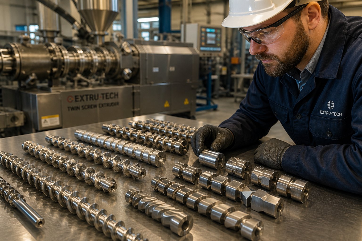
How to Select the Right Twin Screw Extruder for Your Operation
Every section of this article has built toward one practical question: given everything you know about screw configurations, operating parameters, polymer demands, line integration, and cost economics, how do you actually choose the right machine? The answer isn't buried in a single specification or a salesperson's recommendation. It lives in a systematic process that maps your application requirements to equipment capabilities, step by step, before a purchase order ever gets written.
Too many buyers skip this process. They start with a budget number, collect a handful of quotes, and pick the machine that fits the spreadsheet. Six months later, they're fighting vent flooding on a compound the extruder was never designed to handle, or waiting three weeks for replacement kneading blocks from a supplier with no regional inventory. A structured selection framework prevents these failures by forcing the right questions in the right sequence.
Matching Extruder Configuration to Your Application
Whether you're specifying a production-scale compounder for a new plant or evaluating a lab scale twin screw extruder for R&D trials before scaling up, the selection logic follows the same sequence. Each step narrows the field and eliminates configurations that would underperform or overshoot your actual needs.
- Define the target polymer and additive system. This is the non-negotiable starting point. Are you processing thermally sensitive PVC that demands counter-rotating, low-shear conveying? Or compounding glass-fiber-reinforced PA66 that requires high torque density and deep vacuum venting on a co-rotating platform? The polymer dictates the configuration family. The additive system, whether it's 60% mineral filler, 3% liquid coupling agent, or 40% pigment concentrate, determines the screw element sequence, feeding strategy, and barrel metallurgy. Start here, and half the decision makes itself.
- Determine required throughput. Throughput targets drive screw diameter selection. A 26 mm machine handles 5 to 30 kg/h for development work, while an 85 mm unit delivers 1,000 to 2,500 kg/h for full production. Oversize the machine and you waste capital. Undersize it and you're running at maximum capacity from day one with no headroom for growth, recipe changes, or the inevitable throughput loss that accompanies screw wear over time. Budget for at least 20% throughput margin above your current peak demand.
- Choose co-rotating or counter-rotating based on shear and mixing needs. The comparison table from earlier in this article maps these configurations against shear intensity, mixing quality, pressure generation, and typical applications. If your process demands intense dispersive mixing, self-wiping, and high-speed operation, co-rotating is the answer. If you need gentle conveying, high die pressure at low speeds, and minimal shear heating, counter-rotating wins. This is a binary choice with massive downstream consequences, so don't let price alone drive it.
- Select the appropriate L/D ratio for residence time requirements. Count the unit operations your process demands: feeding, melting, mixing, side feeding of fillers, atmospheric venting, vacuum venting, and metering. Each operation needs barrel length. Complex compounding with multiple additive stages and deep degassing pushes you toward 44:1 to 52:1. Simpler blending or direct extrusion stays comfortable at 32:1 to 40:1. If you're uncertain, a laboratory twin screw extruder running your actual formulation at different screw configurations can provide the data you need before committing to a production-scale L/D ratio.
- Specify barrel metallurgy for abrasion or corrosion resistance. Match the barrel liner material to the most aggressive component in your formulation. Glass fibers demand tungsten carbide or iron-boron bimetallic liners. Corrosive PVC and halogenated flame retardants require nickel-chromium-molybdenum alloys. Unfilled commodity resins process fine through standard nitrided steel. Getting this wrong doesn't just shorten barrel life; it contaminates your product with metal particles as the liner erodes.
- Plan the complete line including feeding and pelletizing. Specify gravimetric feeders, side feeders, liquid injection systems, pelletizer type, cooling conveyors, screeners, and packaging equipment in parallel with the extruder. Size every downstream component to handle the extruder's maximum rated throughput plus a safety margin. A line is only as productive as its weakest link, and that link is almost never the extruder itself.
This six-step process works whether you're configuring a benchtop twin screw extruder for a university polymer lab or a 92 mm production compounder for a 24/7 automotive compounding operation. The scale changes, but the logic doesn't. Running pilot trials on a lab scale twin screw extruder before finalizing production specifications is one of the most cost-effective risk mitigation strategies available, yet surprisingly few buyers invest the time. A few hundred kilograms of trial material on a laboratory scale extruder can reveal screw configuration problems, venting inadequacies, and feeding challenges that would cost tens of thousands of dollars to discover on a full-scale machine.
Evaluating Manufacturers and Screw Barrel Partners
The machine is only as good as the organization standing behind it. Twin-screw extruders are long-lifecycle capital assets that require ongoing technical support, spare parts supply, and periodic refurbishment over a 10 to 20 year service life. The manufacturer relationship doesn't end at commissioning; it begins there. Evaluating potential suppliers on the following criteria separates partners who will support your operation long-term from those who disappear after the invoice clears.
- Application engineering support: Can the supplier's engineering team recommend screw configurations, barrel metallurgy, and operating parameters based on your specific polymer and additive system? Or do they simply quote standard catalog models? The best twin-screw extruder manufacturers maintain application labs where they run customer trials on pilot-scale equipment before finalizing production machine specifications.
- Screw element modularity and availability: Verify that the supplier offers a full range of conveying, kneading, mixing, and specialty elements that can be reconfigured as your product portfolio evolves. Proprietary element designs that lock you into a single source for replacements create long-term supply risk.
- Wear parts inventory and lead times: Ask specifically about stocking levels for standard screw elements, kneading blocks, and barrel segments in your machine's diameter class. A supplier who ships replacement parts within days rather than weeks directly reduces the production downtime associated with scheduled maintenance or unexpected wear. This is where screw and barrel partners become critically important. NANHAIYA, for instance, provides screw barrel support for plastic extruder machines across pipe, profile, sheet, pelletizing, and recycling applications, serving as a reliable sourcing option for extrusion manufacturers and recycling plants that need responsive wear-part supply without the lead times often associated with OEM channels.
- Global service capability: If your operations span multiple regions, confirm that the supplier has field service engineers, calibration resources, and spare parts distribution in those geographies. A machine installed in Southeast Asia that depends on parts shipped from Europe faces lead times that a local or regional parts partner can eliminate.
- Training programs: Evaluate the depth and format of operator and maintenance training offered. Classroom instruction at the supplier's facility, on-site commissioning training, and ongoing refresher programs all contribute to longer equipment life and more consistent output quality.
- Reference installations: Request contact information for existing customers running similar polymers and throughput rates. Speaking directly with operators and maintenance managers at reference sites reveals real-world reliability, service responsiveness, and parts longevity data that no sales presentation can replicate.
- Financial stability and longevity: A twin screw extruder purchased today will need parts and service support a decade from now. Suppliers with a proven track record and stable business operations are more likely to maintain the inventory, engineering expertise, and service infrastructure you'll depend on over the machine's full lifecycle.
One final consideration that separates experienced buyers from first-timers: don't evaluate the extruder manufacturer and the screw barrel supplier as entirely separate decisions. In many operations, the wear-part supplier has as much influence on long-term uptime and cost performance as the original equipment manufacturer. Whether you source replacement screws and barrels from the OEM or from a specialized partner like NANHAIYA, confirm that the components meet the same metallurgical specifications, dimensional tolerances, and surface finish standards as the originals. A quality screw barrel partner who understands your application and maintains ready inventory for your machine class is an asset that pays dividends every time a scheduled maintenance window arrives or an unexpected wear event demands fast response.
Selecting the right twin screw plastic extruder is not a single decision. It's a chain of interconnected choices, from polymer chemistry to screw geometry, from barrel metallurgy to pelletizer type, from purchase price to five-year cost of ownership. Each link in that chain reinforces or undermines the others. The buyers who get the best outcomes are the ones who treat the process as a systems engineering exercise, not a purchasing transaction, and who invest the time to validate their choices through pilot-scale testing, supplier evaluation, and honest total cost analysis before committing capital. That discipline, more than any single machine feature, is what separates operations that run profitably for decades from those that spend their first year troubleshooting problems that could have been avoided.
Frequently Asked Questions About Twin Screw Plastic Extruders
1. What is the difference between a co-rotating and counter-rotating twin screw extruder?
Co-rotating twin screw extruders have both screws turning in the same direction, producing high shear, excellent self-wiping action, and superior dispersive and distributive mixing. They run at 400 to 900+ rpm and are ideal for compounding, masterbatch, reactive extrusion, and recycling. Counter-rotating extruders have screws turning in opposite directions, creating a gentle calendering effect with low shear. They operate at 30 to 150 rpm and excel at processing thermally sensitive materials like rigid PVC for pipes and profiles. The choice depends on whether your application prioritizes intense mixing or gentle, high-pressure conveying.
2. What L/D ratio should I choose for my twin screw extruder?
The ideal L/D ratio depends on your process complexity. Ratios of 40:1 to 52:1 suit complex compounding with multiple additive stages, deep vacuum degassing, and reactive extrusion because they provide more barrel zones and longer residence time. Shorter ratios of 24:1 to 32:1 work for simpler blending, direct PVC profile extrusion, or thermally sensitive polymers where minimizing heat exposure matters. Count the unit operations your process requires, including feeding, melting, mixing, side feeding, venting, and metering, then select an L/D ratio that accommodates each stage without excessive unused barrel length that wastes energy.
3. How much does a twin screw plastic extruder cost?
Purchase price varies significantly based on screw diameter, L/D ratio, torque class, barrel metallurgy, and control system complexity. Machines in the 30 to 40 mm range typically fall between $50,000 and $120,000, while 70 to 90 mm production units can reach $250,000 to $500,000 or more. However, the initial price is only part of the equation. Total cost of ownership over five to ten years includes energy consumption, screw element and barrel liner replacements, preventive maintenance, and unplanned downtime. A lower-priced machine that wears faster and consumes more energy can cost significantly more over its operating life than a premium alternative.
4. Can twin screw extruders be used for plastic recycling?
Yes, twin screw extruders have become the preferred platform for demanding mechanical recycling applications. Their superior mixing homogenizes variable-quality post-consumer and post-industrial feedstocks, while modular screw profiles can be reconfigured as incoming waste streams change. Multiple atmospheric and vacuum venting zones extract moisture, trapped air, residual odors, and degradation byproducts that single screw machines struggle to remove. The twin screw advantage becomes decisive above approximately one tonne per hour throughput, where consistent melt quality, effective degassing, and minimal gel formation are critical for producing saleable recycled pellets.
5. How often do screw elements and barrels need replacement on a twin screw extruder?
Replacement frequency depends heavily on the abrasiveness of processed materials. Unfilled resins like neat PP or PE allow screw and barrel components to last 5 to 10 years. Mineral-filled compounds at 20 to 40% loading typically require replacement every 3 to 5 years. Glass-fiber-reinforced compounds are the most demanding, often wearing kneading and mixing elements within 12 to 24 months. Monitoring screw-to-barrel clearance monthly helps catch wear before it degrades output quality. Using bimetallic barrel liners and wear-resistant screw element coatings extends service life, and sourcing from reliable screw barrel partners like NANHAIYA ensures fast replacement lead times to minimize production downtime.
Written by
Nanhaiya Technical Team
Zhoushan Nanhaiya Plastic Machinery Co., Ltd.
The Nanhaiya technical team supports screw and barrel manufacturing projects through application review, technical communication, custom manufacturing coordination, and production and quality control.
Discuss Your Application
Related Articles
More insights on screw barrel technology and plastics processing.

What Nobody Tells You About Screw Barrel For Plastic Machine Design
Oct 10, 2026
Learn how screw barrel for plastic machine design affects melt quality, throughput, and wear life. Covers geometry, resin matching, troubleshooting, and sourcing.
Read Article
Single Screw Extruder for Sheet: Stop Guessing, Start Specifying
Oct 9, 2026
Learn how to specify a single screw extruder for sheet production. Covers screw geometry, resin-specific processing, troubleshooting, and maintenance best practices.
Read Article
PE Pipe Extruder Machine: What Datasheets Won't Tell You
Oct 9, 2026
Learn how a PE pipe extruder machine works, key specs explained, material grade selection, maintenance tips, and buyer guidance beyond the datasheet.
Read ArticleLooking for something else?
Search by material, symptom or product and jump straight to the relevant page.
These are navigation suggestions based on keyword matching — not a quotation, not a delivery commitment, and not a substitute for engineering review. Final specification is confirmed by our engineers against your drawings and processed material.
Need help with screw barrel selection?
Share your machine model, processed material and application. Our team can help with pricing and technical support.