

What Is a Twin Screw Pipe Extruder and Why It Matters
Imagine running a pipe production line that consistently turns out product with uneven wall thickness, rough surfaces, or subtle dimensional drift. You have checked the downstream equipment, adjusted the haul-off speed, and swapped out the die — yet the defects persist. In many cases, the root cause traces straight back to the extruder itself and how well it plasticizes, mixes, and delivers the polymer melt.
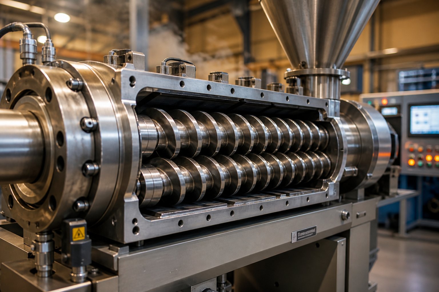
A twin screw pipe extruder is a thermoplastic processing machine that uses two intermeshing screws rotating inside a heated barrel to melt, homogenize, and push polymer compound through a pipe die head, producing continuous hollow profiles with uniform wall thickness and consistent dimensional accuracy.
That definition separates it from general-purpose twin screw extruders used for compounding, masterbatch production, or film processing. A twin screw pipe extruder is purpose-built around a pipe die and calibration system, and every aspect of its screw geometry, barrel zoning, and pressure delivery is optimized for creating round, concentric hollow sections rather than flat sheets or pelletized output.
Defining the Twin Screw Pipe Extruder
At its core, the machine relies on two screws that intermesh as they rotate within a temperature-controlled barrel. This twin screw arrangement creates a self-wiping action that prevents material from stagnating against the barrel wall — a feature that directly improves melt uniformity. Raw polymer, whether powder or pellets, enters through a feed hopper, travels through sequential heating and compression zones, and exits as a pressurized, homogeneous melt stream directed into the die head. The result is a continuously formed pipe with controlled diameter, wall thickness, and surface finish.
Compared to a single-screw alternative, a twin-screw extruder delivers superior mixing, more precise shear control, and steadier melt pressure at the die. These advantages become critical when you need tight dimensional tolerances on every meter of pipe rolling off the line.
Why Pipe Manufacturers Rely on Twin Screw Technology
PVC dominates the global plastic pipe market, and PVC is notoriously heat-sensitive. Push the melt temperature even a few degrees too high and the material degrades, discolors, and loses impact strength. A PVC extruder built on twin screw architecture handles this challenge by offering gentle yet thorough plasticizing — low shear where it matters, intensive mixing where additives like stabilizers, lubricants, and pigments need to be dispersed evenly throughout the compound.
Twin screw extruders are not limited to PVC, however. Manufacturers also use them for HDPE, PP, and wood-plastic composite (WPC) pipe applications where compound homogeneity and consistent output pressure are essential to finished product quality.
This article dives deep into the specifics that determine whether your extruder performs at its potential or quietly underdelivers. You will find detailed coverage of working principles, conical versus parallel configuration comparisons, process parameter optimization, practical troubleshooting for common pipe defects, and component selection guidance — all examined through the lens of pipe manufacturing rather than generic extrusion theory. The goal is straightforward: help you identify exactly where performance losses hide and what to do about them.
How the Twin Screw Extrusion Process Produces Pipe
A pipe that meets spec on every measured dimension — wall thickness, outer diameter, roundness, surface finish — starts well before the die head. It starts in the first few centimeters of the screw channel, where raw material enters the barrel. Every stage of the twin screw extrusion process builds on the one before it, and a weakness at any point cascades downstream into a defect you will eventually catch at quality control, or worse, at a customer's job site.
Here is a stage-by-stage look at how raw polymer becomes finished pipe inside a twin screw pipe extruder, and why each phase matters more for pipe than for many other extruded products.
- Feeding and solid conveying — raw material enters the barrel and is transported forward.
- Melting and plasticizing — the polymer compound is converted into a uniform, homogeneous melt.
- Metering and die delivery — the melt is pressurized and pushed through the pipe die head at a stable, consistent rate.
Feeding and Solid Conveying in the Intake Zone
When you produce pipe, wall thickness uniformity is non-negotiable. A water pressure pipe with a thin spot is a liability; a sewer pipe with an inconsistent wall fails structural requirements. That uniformity begins with how steadily raw material flows into the extruder barrel.
Polymer — typically PVC dry blend powder or polyolefin pellets — drops from a feed hopper into the screw channels at the intake zone. The twin screws grab the material and push it forward through positive displacement, meaning a defined volume moves with each screw rotation regardless of friction conditions. This is fundamentally different from single-screw machines, where material transport depends heavily on the friction coefficient between polymer and barrel wall.
The feeding system itself plays a critical role. Two common approaches exist: volumetric feeders, which deliver material based on a set volume per unit time, and gravimetric feeders, which continuously weigh the material and adjust feed rate in real time. For pipe extrusion, gravimetric dosing is the preferred choice. Why? Because even small fluctuations in material density — common with PVC dry blends that can vary in bulk density from batch to batch — cause volumetric feeders to deliver inconsistent mass flow. That inconsistency translates directly into wall thickness variation in the finished pipe.
Gravimetric systems eliminate this variable by measuring actual weight, compensating automatically for density shifts. The payoff is significant: saving just 1-2% of dry blend through reduced overweight can pay back the cost of a gravimetric system in under a year, and reducing reject material through tighter control saves roughly two-thirds of the raw material cost that scrap represents. For pipe manufacturers running high-volume lines, that precision at the feed throat is the first link in the quality chain.
Melting and Plasticizing Through Intermeshing Screws
Picture the material moving past the intake zone and entering the compression and melting sections of the barrel. Here is where the twin screws do what no single screw can match for heat-sensitive compounds: they plasticize the polymer with controlled, uniform shear while preventing any material from sitting idle against the barrel wall.
The key mechanism is self-wiping. Because the two screws intermesh — each screw flight sweeps the surface of the opposing screw — material is constantly scraped away, turned over, and re-exposed to fresh barrel surface. This does three important things for pipe quality:
- Prevents material stagnation. Stagnant material in a barrel pocket overheats and degrades, creating black specks or weak points in the pipe wall. Self-wiping twin screws virtually eliminate dead zones.
- Ensures melt homogeneity. Every particle of polymer receives a similar thermal and mechanical history. The result is a melt with consistent viscosity across its entire cross-section — essential for producing pipe with a smooth inner and outer surface.
- Improves additive dispersion. PVC pipe compounds contain stabilizers, lubricants, impact modifiers, and pigments that all must be distributed evenly. The intermeshing action creates a combination of distributive and dispersive mixing that spreads these additives uniformly throughout the melt, so the finished pipe has consistent color, impact resistance, and weathering performance along its entire length.
Screw geometry governs how much mechanical energy the polymer absorbs during this stage. Parameters like flight depth, pitch, and compression ratio determine the shear rate — the speed at which polymer layers slide against each other and generate frictional heat. For PVC pipe production, this balance is critical. Too much shear raises the melt temperature beyond PVC's narrow processing window, triggering thermal degradation that shows up as yellow discoloration or reduced impact strength. Too little shear leaves the compound under-plasticized, producing pipe with a rough surface and poor mechanical properties.
You will notice that experienced operators pay close attention to screw torque readings during production. A sudden rise in torque often signals a change in material feed consistency or a shift in melt viscosity — both early warnings that pipe quality may be drifting before any visible defect appears.
Metering and Die Delivery for Consistent Pipe Profiles
The final stage inside the barrel is the metering zone, and its job is deceptively simple: build stable pressure and deliver the melt to the pipe die head at a perfectly constant rate. In practice, this is where many screw extrusion systems fall short without operators realizing it.
The metering zone features screw channels with a consistent, shallow depth designed to pressurize the fully molten polymer. Stable melt pressure at this point is non-negotiable for pipe. Even minor pressure fluctuations — swings of just a few bar — cause the melt to flow unevenly through the annular gap of the die, producing pipe with measurable wall thickness variation. In severe cases, pressure surging creates visible diameter changes that render entire production runs out of spec.
Counter-rotating twin screws, the configuration most common in PVC pipe extruders, excel here because their positive conveying action produces inherently steadier output pressure compared to co-rotating or single-screw designs. The material moves forward in enclosed C-shaped chambers between the screw flights and barrel wall, with minimal backflow leakage. This means the melt arrives at the die head with a narrow pressure variation window — exactly what you need for round, concentric pipe.
The connection between metering performance and downstream results is direct and measurable. Consistent melt pressure produces consistent pipe wall thickness. Consistent melt temperature produces consistent pipe diameter. And consistent melt homogeneity produces consistent surface finish and mechanical properties. When any of these parameters drift, the defects appear not at the extruder but meters downstream — in the calibration tank, at the haul-off, or at the cutting station — making it easy to misdiagnose the source.
That relationship between what happens inside the barrel and what you see at the end of the line raises a practical question: for a given pipe material and application, which twin screw configuration — conical or parallel — delivers the best combination of gentle plasticizing and stable metering? The answer depends on factors that go well beyond simple machine specs.
Conical vs Parallel Twin Screw Extruders for Pipe Applications
Two pipe manufacturers can invest in twin screw technology and still end up with dramatically different results — not because one bought a "better" machine, but because one chose the wrong screw configuration for the material being processed. The choice between a conical twin screw extruder and a parallel twin screw extruder shapes everything from plasticizing behavior and shear intensity to throughput potential and die pressure stability. For pipe production specifically, this decision determines whether your line runs at peak efficiency or struggles with process limitations that no amount of parameter tweaking can overcome.
Conical Twin Screw Extruders and Their Dominance in PVC Pipe
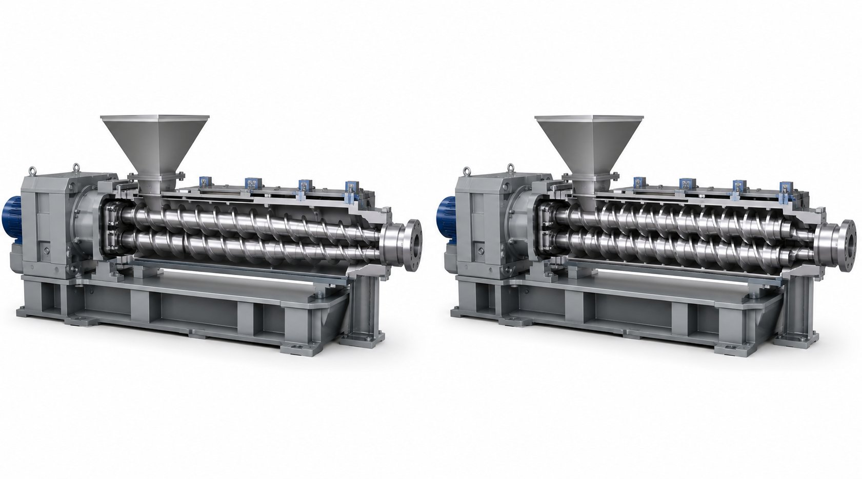
Imagine two screws that taper from a large diameter at the feed end to a significantly smaller diameter at the discharge. That is the defining geometry of a conical twin screw extruder — and it is purpose-built for the exact challenges PVC pipe presents.
The oversized feed zone is the first advantage. PVC dry blend is a bulky, low-density powder with poor flow characteristics. A conical design accommodates this volume-hungry material by providing a large intake area where the screws can grab and convey powder efficiently without starving or bridging. As the material travels forward along the tapered screws, the channel volume progressively decreases, creating natural compression that gently densifies and plasticizes the compound without abrupt shear spikes.
This progressive compression matters enormously for PVC. Unlike polyolefins, PVC has no true melting point — it degrades before it flows freely, so the processing window is narrow. Conical extruders typically run in a counter-rotating, intermeshing configuration at relatively low screw speeds (commonly 30 to 150 RPM). The opposing rotation creates enclosed C-shaped pockets that positively convey material with minimal backflow, delivering the kind of low-shear, high-pressure output that PVC pipe demands. The result is thorough gelation without the thermal overshoot that destroys impact strength and causes discoloration.
This is exactly why counter-rotating conical machines dominate rigid PVC pipe production — from small-diameter plumbing tubes to large infrastructure water mains. They handle UPVC, CPVC, and high-fill calcium carbonate PVC formulations with predictable, repeatable results.
Parallel Twin Screw Extruders for Specialty Pipe Applications
A parallel twin screw extruder takes a fundamentally different approach. Both screws maintain a constant diameter along their entire length, and they typically operate in a co-rotating configuration — screws turning in the same direction with fully intermeshing flights.
Where does this fit in pipe extrusion? Think specialty applications. A co rotating twin screw extruder generates significantly higher shear rates and more intensive distributive mixing than its conical counterpart. Material follows a figure-eight flow path between the screws, getting repeatedly split, reoriented, and recombined. This aggressive mixing action is overkill for standard PVC pipe, but it becomes essential when you are producing:
- Wood-plastic composite (WPC) pipe and profiles — where wood flour must be thoroughly dispersed into the polymer matrix to prevent weak spots and surface defects.
- Heavily filled PP or PE pipes — where mineral fillers at 40% or higher loading require intensive mixing energy to achieve homogeneous distribution.
- Multi-material or compounding-intensive pipe systems — where the extruder functions partly as a twin screw compounding extruder, blending and reacting components inline before shaping them into pipe.
Parallel co-rotating machines also offer greater design flexibility. Their modular barrel and screw element construction allows manufacturers to reconfigure mixing zones, add side feeders, or introduce venting ports — an advantage when processing formulations that evolve over time. However, the higher shear intensity and faster screw speeds (often 200 to 600+ RPM) generate more viscous dissipation heat, which makes them a poor match for thermally sensitive PVC unless specifically engineered with restrictive screw profiles.
Understanding co rotating and counter rotating twin screw extruder configurations in the context of pipe production is not just academic — it directly determines whether your line delivers consistent quality or fights constant process instability.
Selecting the Right Configuration for Your Pipe Application
So how do you choose? The decision comes down to matching machine characteristics to your material and application requirements. The following table puts the key differences side by side:
| Feature | Conical Twin Screw Extruder | Parallel Twin Screw Extruder |
|---|---|---|
| Screw Geometry | Tapered — large feed end, small discharge end | Constant diameter along full length |
| Typical Rotation Direction | Counter-rotating | Co-rotating |
| Screw Speed Range | 30 - 150 RPM | 200 - 900+ RPM |
| Shear Intensity | Low to moderate — gentle processing | Moderate to high — intensive mixing |
| Mixing Capability | Good for pre-blended compounds | Excellent distributive and dispersive mixing |
| Feed Handling | Excels with bulky powders (PVC dry blend) | Better suited for pellets and pre-densified feeds |
| Pressure Generation | High — natural compression from taper | Moderate — relies on screw element configuration |
| Processing Window | Can be narrower for achieving optimal gelation | Wider — more room for parameter adjustment |
| Modular Flexibility | Limited — custom taper restricts reconfiguration | High — barrel sections and screw elements are interchangeable |
| Typical Pipe Materials | PVC, CPVC, high-fill PVC compounds | WPC, filled PP/PE, compounded specialty polymers |
| Best-Fit Pipe Applications | Standard rigid PVC pipe (water, sewer, conduit) | Filled pipe, composite pipe, specialty multi-material pipe |
Here is a practical rule of thumb: if your primary business is standard PVC pipe, the conical counter-rotating configuration remains the established, proven choice. It handles PVC dry blend efficiently, delivers the stable die pressure pipe sizing demands, and operates with lower energy input per kilogram of output. If your product line extends into WPC pipe, heavily mineral-filled pipe, or applications requiring inline compounding, a parallel co-rotating design gives you the mixing intensity and formulation flexibility those products require.
Keep in mind that choosing the right screw configuration is only half the equation. The real-world performance difference between a twin screw pipe extruder and a single screw alternative — and the situations where each type earns its place on the production floor — often surprises manufacturers who have not evaluated both options side by side.
Twin Screw vs Single Screw Extruders in Pipe Manufacturing
You already know the differences between conical and parallel twin screw configurations. But here is a more fundamental question that too many pipe manufacturers skip over entirely: does your application actually need a twin screw extruder at all, or would a single screw extruder deliver equal results at lower cost and complexity?
The answer is not always obvious. Choosing the wrong architecture — a double screw extruder where a single screw would suffice, or a single screw machine where twin screws are essential — costs manufacturers thousands in unnecessary capital spending, excess energy consumption, or chronic quality problems that no amount of operator skill can fix.
Single Screw Extruders in Pipe Production
A single screw extruder uses one rotating screw inside a heated barrel to convey, melt, and pressurize polymer into the die. It is the workhorse of polyolefin pipe production — HDPE water mains, PP drainage pipe, PE gas distribution lines — for several straightforward reasons.
These materials arrive as pre-compounded, thermally stable pellets. The resin supplier or compounder has already blended the base polymer with stabilizers, pigments, and processing aids into a uniform granule. The extruder's job is simply to remelt that pellet and deliver a steady melt stream to the pipe die. A single screw extruder handles that duty well because:
- The mechanical design is simpler. One screw, one drive system, fewer wear components — translating to lower capital cost and easier maintenance.
- Pellet feeding is reliable. Uniform granules flow freely and convey consistently via friction-driven transport, which is exactly how a single screw conveys material.
- Melt delivery is stable. For pre-compounded pellets that do not require intensive mixing inside the barrel, a single screw extruder builds pressure and delivers a consistent melt stream to the die with adequate uniformity.
For many PE and PP pipe lines, a single screw extruder is not a compromise — it is the right tool. The material does not demand heavy mixing, the thermal processing window is wide, and the simpler machine runs reliably shift after shift.
Where Twin Screw Extruders Outperform for Pipe
So when does the equation change? When the material, formulation, or quality requirement exceeds what a single screw can deliver.
Consider PVC dry blend. Unlike polyolefin pellets, PVC dry blend is a fluffy, low-bulk-density powder that requires in-line plasticizing — the extruder itself must convert raw powder into a fully gelled, homogeneous melt. Single screw extruders struggle with this task. Their friction-dependent transport mechanism handles powder poorly, often causing inconsistent feeding, incomplete plasticizing, and material degradation from uneven shear.
Twin screw extruders solve these problems through forced displacement conveying that moves material forward regardless of friction conditions. As industry analysis from Rollepaal highlights, the intermeshing screws transport material in C-ring shaped chambers, providing much higher pump efficiency compared to single screw designs — a benefit that is particularly important for dry blend PVC, which exhibits more wall slip than polyolefins.
Twin screw extruders become essential or strongly preferred when you face any of these scenarios:
- Processing PVC dry blend directly — eliminating the costly granulation step that single screw systems often require for reliable PVC processing.
- Achieving superior additive dispersion — the self-wiping, intermeshing action distributes stabilizers, lubricants, and impact modifiers far more uniformly than a single screw can.
- Handling thermally sensitive materials — precise shear and temperature control within the narrow PVC processing window reduces degradation risk, lowering heat stabilizer requirements and associated cost.
- Producing pipe with tighter dimensional tolerances — the positive conveying action of counter-rotating twin screws delivers more consistent output pressure, directly translating to better wall thickness uniformity and roundness.
- Running high-output production lines — modern twin screw designs can replace two older single screw lines with one higher-capacity machine, improving floor space efficiency and reducing labor.
The self-wiping mechanism also delivers a narrower residence time distribution, meaning every particle of PVC spends a similar amount of time in the barrel. For a material that degrades with excessive heat history, that consistency is not just a nice feature — it is what separates reliable production from chronic quality firefighting.
Decision Framework for Pipe Equipment Selection
Picking the best extruders for thermoplastics pipe production is ultimately a matching exercise — aligning machine capability with material behavior and product requirements. The table below lays out the critical decision factors side by side:
| Decision Factor | Single Screw Extruder | Twin Screw Extruder |
|---|---|---|
| Material Compatibility | Pre-compounded pellets (HDPE, PP, PE) | PVC dry blend, filled compounds, recycled PVC, WPC |
| Mixing Capability | Low to moderate — adequate for pre-mixed pellets | High — distributive and dispersive mixing for raw blends |
| Temperature Control Precision | Adequate for thermally stable polymers | Superior — critical for heat-sensitive PVC |
| Feed Form Handling | Excellent for uniform pellets; poor for powder | Handles powder, dry blend, and variable-density feeds well |
| Output Pressure Stability | Good with consistent pellet feed | Excellent — forced displacement minimizes pressure fluctuation |
| Throughput Range | Moderate; limited by friction-based conveying | High; modern designs achieve 800+ kg/h for large-diameter pipe |
| Capital Cost | Lower initial investment | Higher initial investment |
| Maintenance Complexity | Simpler — fewer wear components | More complex — two screws, gearbox, and tighter tolerances |
| Total Cost of Ownership | Lower for pellet-based, standard pipe lines | Often lower for PVC dry blend lines (eliminates granulation, reduces scrap) |
| Ideal Pipe Applications | HDPE water/gas pipe, PP drainage, PE conduit | PVC-U pressure/sewer pipe, CPVC, filled pipe, large-diameter PVC pipe |
Here is the bottom line: PVC pipe represents the largest segment of the global plastic pipe market, and for PVC production from dry blend, twin screw extruders are the industry standard for good reason. Their forced displacement conveying, self-wiping action, and narrow residence time distribution address every processing challenge that makes PVC difficult on a single screw machine. The higher capital cost pays for itself through direct dry blend processing, lower stabilizer consumption, reduced scrap, and higher output per line.
For polyolefin pipe manufacturers working with stable, pre-compounded pellets, a quality single screw extruder remains a practical and economical choice. There is no need to add complexity where the material does not demand it.
Whichever architecture sits at the heart of your line, the machine's real-world performance depends heavily on how you set and manage process parameters — temperature profiles, screw speed, and back pressure — that directly control the quality of every meter of pipe you produce.
Key Process Parameters That Control Pipe Quality
Your twin screw pipe extruder might have the ideal screw configuration, the perfect material formulation, and flawless downstream equipment — and still produce pipe with surface roughness, wall thickness variation, or poor impact resistance. Why? Because the process parameters you dial in every shift are what ultimately translate machine capability into actual pipe quality. Temperature profiles, screw speed, and back pressure form a triangle of interdependent variables, and getting any one of them wrong degrades everything downstream.
Here is where many operators and plant managers lose money without realizing it: they treat process settings as static recipes rather than dynamic controls that must respond to shifts in ambient conditions, material batch variation, and equipment wear. Understanding how each parameter influences the melt — and by extension, the finished pipe — is what separates a PVC extruder machine producing consistent product from one that generates chronic scrap.
Temperature Profile Management Across Barrel Zones
PVC does not melt the way polyolefins do. It has no clean melting point — instead, it undergoes a gradual gelation process where primary particles fuse into a homogeneous, entangled melt. The barrel temperature profile directly controls how completely and uniformly this gelation occurs, and even modest miscalculations show up as defects in the finished pipe.
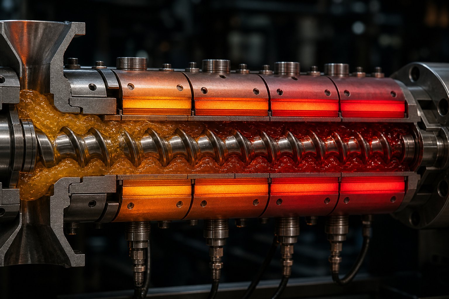
A typical twin screw extruder for polymer pipe production divides the barrel into four controllable zones, each with a specific purpose and temperature target:
| Barrel Zone | Typical Temperature Range (PVC) | Function |
|---|---|---|
| Feed Zone | 150 - 165 °C | Preheats and begins softening the dry blend; too hot here causes bridging and premature melting that blocks material flow |
| Compression Zone | 165 - 175 °C | Progressive plasticizing as channel volume decreases; drives initial fusion of PVC primary particles |
| Metering Zone | 170 - 185 °C | Completes gelation and homogenizes the melt thermally and materially for stable die delivery |
| Adapter / Die | 175 - 190 °C | Maintains uniform melt flow through the annular die gap; controls final surface finish quality |
Notice the pattern: a gradual, controlled escalation from feed to die. This ascending profile matches PVC's unique thermal behavior — gentle heating early to avoid degradation, progressive energy input through the compression section, and final thermal stabilization before the melt enters the die head.
What happens when this profile is wrong? Running too cold produces incomplete gelation. The pipe comes off the line with a rough, matte surface, poor weld line strength, and reduced impact resistance — the PVC particles never fully fused into a cohesive matrix. Operators often see a corresponding spike in screw torque as the machine fights to move under-plasticized material forward.
Running too hot is equally damaging, but in a different way. Excessive temperature triggers PVC thermal degradation — the molecular chains break down, releasing hydrochloric acid gas. You will notice a burning smell near the die, yellowing or brown discoloration in the pipe, and a measurable drop in melt strength that causes the pipe to sag or distort during calibration. Overheating in the metering zone is particularly dangerous because the material has already absorbed significant shear energy from the screws, so even a modest barrel temperature overshoot can push the actual melt temperature past the degradation threshold.
Independent zone control is what makes twin screw systems particularly well-suited for this challenge. Each barrel zone has its own heater band and cooling channel, allowing operators to fine-tune the temperature gradient precisely. The best-performing PVC extruders also incorporate calibrated thermocouple monitoring and heater band performance verification — because a failed heater or drifting sensor can silently shift the temperature profile and introduce defects that seem to appear out of nowhere.
Screw Speed and Its Impact on Melt Quality
Screw speed is the most tempting parameter to push when you need more output. Crank up the RPM, get more pipe per hour — sounds straightforward. But for a thermoplastic extruder processing PVC pipe, screw speed is the single most consequential process variable because it simultaneously affects throughput, shear rate, melt temperature, and residence time.
Here is the physics: as screws rotate faster, they shear the polymer more aggressively. This shearing generates viscous dissipation heat — frictional energy converted directly into melt temperature rise. Research on twin-screw extrusion confirms that motor power consumption increases significantly with screw speed, and the resulting heat buildup reduces melt viscosity while simultaneously narrowing the safety margin before thermal degradation begins.
For PVC pipe, this tradeoff is unforgiving. Increase screw speed by 20% and you might gain 15-18% more throughput — but the melt temperature climbs by several degrees through viscous heating alone, independent of what the barrel heaters are set to. Push too far and you cross into the degradation zone, producing pipe that looks acceptable on the outside but has compromised molecular structure, reduced impact strength, and potential brittleness that only shows up during pressure testing or field service.
Experienced operators optimize this balance by watching three indicators simultaneously:
- Screw torque — rising torque at a given speed suggests the melt viscosity is too high (material too cold or under-plasticized), while falling torque can indicate over-plasticization or degradation.
- Melt temperature at the die — measured directly with an immersion thermocouple, not inferred from barrel zone settings. The actual melt temperature can differ from the barrel set point by 10-20 °C due to viscous dissipation.
- Melt pressure stability — increasing pressure fluctuations at higher speeds signal that the material is not being conveyed uniformly, often because the residence time has shortened to the point where complete gelation is no longer occurring.
Studies on co-rotating twin-screw systems show that specific energy consumption decreases with increasing screw speed — meaning each kilogram of polymer costs less energy to process at higher RPM. But this efficiency gain comes at the cost of melt thermal homogeneity, which deteriorates as throughput rises. For pipe production, where dimensional consistency and mechanical performance are non-negotiable, the optimal screw speed is always a compromise — the fastest speed that still delivers fully gelled, thermally uniform melt within PVC's narrow processing window.
Back Pressure and Melt Homogeneity
Imagine your melt reaching the end of the screw and encountering resistance — the die, the screen pack, the breaker plate. That resistance creates back pressure, and it plays a role in pipe quality that many operators underestimate.
Back pressure forces the melt to work harder to exit the barrel, which does two beneficial things: it increases the residence time in the metering zone (giving the melt more time to thermally equalize) and it improves mixing completeness by enhancing the pressure-driven backflow component that supplements the screw's drag flow. Research into screw performance and melt quality confirms that the pressure flow counteracting drag flow improves mixing effect and melt homogeneity — up to a point.
Too little back pressure and the melt rushes through the metering zone under-mixed. The result is poor thermal homogeneity across the melt cross-section — some regions are hotter, some cooler — which causes uneven flow through the die and visible wall thickness variation in the pipe. Too much back pressure and throughput drops, energy consumption climbs, and the extended residence time raises the risk of thermal degradation in PVC.
Screen packs and breaker plates, positioned between the screw tip and the die adapter, are the primary tools PVC extruders use to regulate back pressure. They also serve as a final filter to catch any unmelted particles or contaminants before the melt enters the die. For pipe extrusion, a clean screen pack ensures that the melt stream reaching the die is free of gels and particles that would create surface defects or weak points in the pipe wall. However, as screens gradually clog during production, back pressure rises — shifting the entire process balance. Monitoring screen pressure differential and changing packs on a defined schedule prevents this creeping quality drift.
Here is a quick-reference summary of how these key process parameters connect directly to the pipe quality outcomes your customers measure:
- Barrel temperature profile → PVC gelation level → impact strength, surface finish, weld line integrity
- Screw speed (RPM) → shear rate and residence time → melt temperature uniformity, throughput rate, degradation risk
- Melt temperature at die → polymer chain integrity → pipe color consistency, long-term pressure rating, brittleness resistance
- Melt pressure stability → flow uniformity through the die → wall thickness consistency, ovality, diameter accuracy
- Back pressure → mixing completeness and thermal homogeneity → pipe density uniformity, surface smoothness, mechanical property consistency along pipe length
- Feed rate consistency → mass flow uniformity → wall thickness variation, weight-per-meter accuracy
Every one of these parameters is adjustable — and every one interacts with the others. Raising screw speed changes the effective melt temperature, which shifts the barrel zone requirements, which alters the back pressure needed for adequate homogeneity. The best-run pipe lines treat these variables as an integrated system, not isolated knobs to turn independently.
Of course, even perfectly optimized process parameters are only as effective as the complete extrusion line allows them to be. The extruder does not produce pipe alone — it feeds a chain of downstream equipment where melt consistency either holds or falls apart.
The Complete Twin Screw Pipe Extrusion Line Explained
A twin screw extruder machine sitting on a factory floor does not produce pipe by itself. It is one station — the central one, yes — inside a coordinated system that stretches from the raw material silo all the way to the finished pipe stacker. Every component upstream feeds the extruder, and every component downstream depends on what the extruder delivers. When manufacturers focus exclusively on extruder specifications and ignore line integration, they invite performance problems that no amount of screw speed adjustment or temperature profile tweaking can fix.
Think of the extrusion line as a chain. The extruder is the strongest link, but any weak link — a fluctuating feeder, a misaligned calibration tank, an unstable haul-off — will limit the quality of the finished pipe. Understanding each station's role, and how it interacts with the extruder's output, is how you move from chasing defects to preventing them.
Upstream Equipment and Material Handling
Before a single granule or particle of powder reaches the barrel, it passes through a series of upstream systems that determine how consistently the extruder can do its job. This upstream chain typically includes:
- Raw material storage silos — holding PVC dry blend, polyolefin pellets, or compound batches in climate-controlled conditions to prevent moisture absorption and flow property changes.
- Hot and cold blending systems — for PVC production, high-speed hot mixers combine resin with stabilizers, lubricants, pigments, and fillers at elevated temperatures, followed by a cooling mixer that brings the blend to a stable, free-flowing state. The consistency of this blending step directly affects how uniformly the extruder can plasticize the material. As Rollepaal's research on material handling emphasizes, the entire chain from storage and mixing through to packaging influences final pipe consistency.
- Conveying and dosing systems — pneumatic or vacuum conveyors transport the blended material to the extruder hopper, where the feeding system meters it into the barrel at a controlled rate.
The choice between gravimetric and volumetric feeding deserves special attention here because it affects a twin-screw extruder machine differently than a single screw system. Twin screw extruders use positive displacement conveying — each screw rotation moves a fixed volume of material forward. This means the extruder itself is less forgiving of feed rate inconsistencies. If the feeder delivers 3% more material for thirty seconds, that surplus does not simply accumulate in the feed throat the way it might on a friction-dependent single screw machine. Instead, it pushes through the barrel and arrives at the die as a pressure spike, producing a measurable wall thickness increase in the pipe.
Gravimetric feeders solve this by continuously weighing material flow and making real-time corrections to keep mass throughput constant. For any extruder system producing pipe to tight tolerances, gravimetric dosing is the first investment that pays for itself — often within months through reduced overweight and lower scrap rates.
Downstream Equipment From Die to Finished Pipe
Once the melt exits the barrel, it enters a sequence of downstream stations that shape, size, cool, pull, mark, and cut the pipe. Each station has a specific job, and each one is sensitive to the consistency of what the extruder delivers. Here is the complete downstream sequence in a typical double screw extruder machine pipe line:
- Pipe die head and mandrel — the melt flows through an annular gap between an outer die ring and an inner mandrel, forming the initial hollow pipe profile. Spider legs or spiral channels inside the die distribute the melt evenly around the circumference. Die design is critical — spider dies are common for PVC, while spiral mandrel dies are typical for polyolefin pipe. A poorly designed or worn die produces uneven wall distribution and visible weld lines that no downstream adjustment can correct.
- Vacuum calibration tank — the soft, hot pipe enters a water-filled tank where external vacuum pulls the pipe's outer surface against a precision-machined calibration sleeve. This station locks in the outside diameter and roundness while the pipe is still pliable enough to be shaped. Vacuum stability here is essential — even small fluctuations cause OD drift and ovality that persist through the rest of the line.
- Spray or immersion cooling tanks — additional cooling sections remove residual heat from the pipe wall, solidifying the material fully. Consistent water temperature and flow coverage matter more than cooling intensity. Uneven cooling creates internal stress that can cause warping, ovality, or long-term dimensional instability after the pipe leaves the factory.
- Haul-off unit — caterpillar-style belt pullers or rubber-padded tracks grip the cooled pipe and draw it through the line at a precisely controlled speed. The haul-off speed, relative to the extruder's melt output rate, directly controls wall thickness. Speed the haul-off up and the pipe wall gets thinner; slow it down and the wall gets thicker. Consistent speed synchronization between the extruder and haul-off is what keeps wall thickness within tolerance meter after meter.
- Marking and printing station — inkjet or hot-stamp printers apply product identification, size, material grade, production date, and standards compliance markings to the pipe surface. Marking must occur after the pipe has cooled enough for ink adhesion but before cutting.
- Saw or planetary cutter — the continuous pipe is cut to specified lengths. Planetary cutters rotate around the pipe to cut without stopping the line, while traveling saws clamp onto the pipe and travel with it during the cut. Accurate cutting depends on consistent line speed — which loops back to haul-off stability and, ultimately, to how steadily the extruder delivers melt.
Notice how many downstream problems trace back to the extruder. Inconsistent melt pressure from the barrel creates flow surges that the die amplifies into wall thickness variation. Temperature fluctuations in the melt cause diameter changes that the calibration tank cannot fully compensate for. Poor melt homogeneity produces weak weld lines at the die's spider legs that persist through cooling and show up as failure points in pressure testing.
A pipe extrusion line performs only as well as its least consistent station — and the extruder's melt quality sets the ceiling for every station that follows.
This system-level perspective matters when you are making purchasing decisions. Evaluating a twin screw extruder machine in isolation — comparing screw diameter, motor power, and maximum throughput — misses the bigger picture. The real question is how well that extruder integrates with your die tooling, your calibration equipment, and your haul-off controls. A high-output extruder paired with an undersized calibration tank or an unstable haul-off will not deliver better pipe — it will produce defects faster.
Smart manufacturers evaluate the full line as an integrated system, matching extruder output stability to downstream capacity and control precision. That alignment is what transforms a collection of individual machines into a production line that holds tolerance run after run.
Even with a perfectly integrated line, however, defects still happen. The question is whether you can diagnose them quickly and trace each symptom back to its root cause — a skill that separates efficient pipe plants from those that lose hours chasing problems in the wrong part of the line.
Troubleshooting Common Twin Screw Pipe Extrusion Defects
A rough surface on a PVC pipe. A wall thickness reading that drifts outside tolerance every few meters. A faint yellow tinge where there should be clean white. Each of these defects tells a specific story about what went wrong inside the barrel, at the die, or somewhere downstream — and misreading that story sends operators chasing fixes in the wrong place, burning hours and wasting material.
Pipe extrusion defects fall into two broad categories: surface defects that affect appearance and structural integrity, and dimensional defects that put the pipe out of specification. Both types frequently originate upstream at the extruder screw and barrel level, even when they only become visible meters downstream at the calibration tank or cutter. Understanding the root cause behind each symptom is what turns reactive troubleshooting into targeted correction.
Surface Defects and Their Root Causes
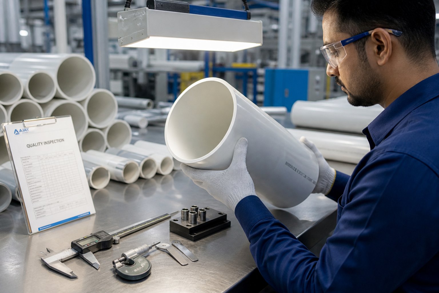
Surface quality is often the first thing a quality inspector checks, and it is the fastest indicator that something has shifted in the extrusion process. Three surface defects dominate twin screw pipe production lines:
Surface roughness is the most common complaint. When you run your hand along the pipe and feel a gritty, matte texture instead of a smooth finish, the melt did not fully gel before reaching the die. Incomplete gelation means PVC primary particles never fused into a cohesive, entangled melt — they passed through the die as partially softened grains rather than a homogeneous flow. The typical cause? Barrel temperatures set too low in the compression or metering zones, or screw speed pushed too high relative to the temperature profile, shortening residence time below what complete plasticizing requires. Contamination — foreign particles or degraded material fragments — can also roughen the surface by creating localized flow disruptions at the die exit. As engineering analysis of twin extruder die performance confirms, poor melt homogeneity from the screw directly produces surface roughness that no die adjustment can compensate for.
Die lines appear as fine, continuous streaks running along the pipe's length. They look like someone lightly scratched the surface with a needle — consistent, repeating, and always in the extrusion direction. The cause is almost always mechanical: damaged or scored die lips, material buildup (plate-out) in the die land area, or a nick on the mandrel surface. Each imperfection in the die's polished flow channel imprints itself into the soft melt as it exits. The fix starts with inspecting and cleaning the die — but if die lines reappear quickly after cleaning, check whether the melt itself is carrying degraded particles that re-deposit on die surfaces. That points back to the barrel, where overheating or dead zones create degraded material that contaminates an otherwise clean melt stream.
Melt fracture shows up as a dramatic surface distortion — spiral patterns, sharkskin ridges, or a heavily textured "orange peel" finish. This defect occurs when the melt velocity at the die exit exceeds the polymer's ability to relax elastically. In practical terms, you are pushing material through the die gap faster than the polymer chains can reorganize after the extreme shear they experience in the land area. Reducing extrusion speed, increasing die temperature to lower melt viscosity, or widening the die gap typically resolves melt fracture. For twin screw systems specifically, checking whether screw speed is driving excessive throughput relative to die capacity is the first diagnostic step.
Dimensional Defects in Pipe Extrusion
Dimensional defects are less immediately visible than surface problems, but they carry higher consequences — a pipe that fails a wall thickness or diameter specification gets rejected entirely, regardless of how smooth its surface looks.
Wall thickness variation is the most costly dimensional defect in pipe production. When you measure around the pipe's circumference and find one side consistently thicker than the other, or when thickness drifts over time along the pipe length, the root cause typically sits in one of three places:
- Inconsistent melt pressure from the extruder — pressure surging causes the melt to flow unevenly through the annular die gap, creating thick and thin spots that repeat with each pressure cycle. This is often the result of feeding inconsistencies, worn screw flights that allow backflow, or improper screw speed settings.
- Uneven die gap settings — if the centering bolts that position the mandrel relative to the outer die ring are not adjusted correctly, one side of the annular gap is wider than the other, producing a pipe that is consistently eccentric.
- Haul-off speed instability — fluctuations in pull speed stretch the pipe unevenly, creating periodic thickness variation that shows up as a wave pattern when you plot wall thickness over length.
Ovality — a pipe that is not perfectly round — usually originates downstream rather than at the extruder, but the extruder contributes indirectly. Uneven cooling in the calibration tank, insufficient vacuum pressure, or a calibration sleeve that does not match the target OD all produce oval cross-sections. However, if the melt arrives at the die with uneven temperature distribution — hotter on one side of the annular flow — the pipe exits the die with asymmetric melt strength, making it more susceptible to deformation during calibration. That uneven melt temperature often traces back to a worn barrel that creates hot spots from inconsistent shear.
Diameter drift describes a gradual change in the pipe's outside diameter over time during a production run. You might start the shift within tolerance and find the pipe trending oversize or undersize an hour later. The most common cause is melt temperature fluctuation — as the barrel heats up during extended operation or as screen packs gradually clog and raise back pressure, the melt viscosity changes. Lower viscosity melt swells less at the die exit, producing a slightly smaller pipe; higher viscosity melt swells more. Monitoring melt temperature and screen pressure differential during production catches this drift before it pushes pipe out of spec.
Systematic Troubleshooting Approach
Chasing individual defects one at a time is inefficient. A systematic approach starts by categorizing the defect, identifying its most probable cause within the twin screw system, and applying targeted corrective actions. The following reference table covers the defects most frequently encountered on twin screw pipe extrusion lines:
| Defect Type | Visual Appearance | Likely Root Cause in Twin Screw System | Recommended Corrective Action |
|---|---|---|---|
| Surface Roughness | Gritty, matte texture; lacks gloss | Incomplete gelation from low barrel temperature or excessive screw speed reducing residence time | Increase compression/metering zone temperatures by 3-5 °C; reduce screw RPM to extend plasticizing time; verify feeder consistency |
| Die Lines | Fine longitudinal streaks along pipe length | Damaged die lip, plate-out buildup on die land, or degraded material from barrel dead zones depositing on die surfaces | Remove and polish die lips; clean die land thoroughly; check for barrel overheating zones producing degraded material |
| Melt Fracture / Sharkskin | Spiral patterns, fine ridges, or orange-peel texture | Excessive melt velocity at die exit relative to polymer relaxation capability; throughput too high for die geometry | Reduce screw speed to lower throughput; increase die zone temperature by 5-10 °C; consider wider die gap if defect persists |
| Wall Thickness Variation | Uneven wall around circumference or periodic thickness waves along length | Melt pressure surging from worn screw flights, feeding inconsistency, or haul-off speed fluctuation | Check extruder screw and barrel clearances for wear; calibrate gravimetric feeder; verify haul-off drive stability and synchronization |
| Ovality (Out-of-Round) | Elliptical cross-section instead of circular | Uneven melt temperature distribution from barrel hot spots or worn barrel; insufficient calibration vacuum; asymmetric cooling | Inspect barrel for wear-induced hot spots; verify vacuum calibration tank seal and pressure; ensure uniform water coverage in cooling tank |
| Yellowing / Discoloration | Yellow, brown, or dark streaks in otherwise white or light-colored pipe | Thermal degradation from excessive melt temperature — barrel zones set too high, screw speed generating too much viscous heat, or material stagnation in worn barrel clearances | Lower metering zone and die temperatures; reduce screw speed; inspect twin screw and barrel for wear that creates dead zones; check material for moisture or contamination |
| Diameter Drift | OD gradually trending oversize or undersize during production run | Creeping melt temperature change from screen pack clogging (raising back pressure) or barrel thermal drift during extended operation | Monitor and log melt temperature and screen pressure differential; establish screen change schedule; verify barrel heater band function across all zones |
One pattern jumps out from this table: a significant number of pipe defects — surface roughness, wall thickness variation, discoloration, ovality — can originate at the extruder screw and barrel itself, even when operators assume the problem lies elsewhere in the line. This is because screw and barrel wear is gradual and silent. As diagnostic research into worn screw barrel symptoms demonstrates, increased clearance between screw flights and barrel wall reduces conveying efficiency, allows backflow, and creates inconsistent shear that manifests as hot spots and pressure fluctuation. The output drops, energy consumption rises, and defects worsen progressively — but because the degradation happens over weeks or months, operators often attribute the symptoms to material variation, die wear, or downstream equipment issues.
Here is a practical rule: when you have eliminated obvious causes — material batch changes, die condition, downstream settings — and defects persist or gradually worsen, measure your screw flight clearances. Worn screw extruders and polymer extruder systems operating with excessive barrel clearance cannot maintain the melt pressure stability and thermal uniformity that pipe production demands, no matter how carefully you set your process parameters. At that point, the issue is mechanical, and the fix is component replacement rather than process adjustment.
That realization — that many chronic quality problems actually live inside the barrel — raises a critical follow-up question: how do you choose the right replacement screws and barrels to restore performance, and what role does screw geometry and metallurgy play in determining how long that performance lasts?
How Screw and Barrel Selection Drives Pipe Performance
You can have the perfect temperature profile, a flawlessly calibrated feeder, and a pristine die — but if the screws and barrel inside your extruder are wrong for the application or worn beyond tolerance, none of those upstream investments deliver their full value. The extruder screw and barrel are where polymer transformation actually happens. They determine how completely the material gels, how uniformly additives disperse, and how stable the melt pressure remains at the die. Choosing the right components — and replacing them before silent wear erodes performance — is one of the highest-return decisions a pipe manufacturer can make.
How Screw Geometry Shapes Plasticizing Performance
Imagine two conical screws with identical outer dimensions but different flight depths, compression ratios, and lead angles. Drop the same PVC dry blend into both, and you will get dramatically different pipe quality off the line. That is because screw geometry is not just a mechanical detail — it is a processing recipe encoded in steel.
Four design parameters matter most for pipe extrusion:
- Compression ratio — the ratio of channel volume at the feed end to channel volume at the discharge. Higher compression ratios generate more intensive plasticizing but also more shear heat. For PVC pipe, a moderate compression ratio provides thorough gelation without pushing melt temperature past the degradation threshold.
- Flight depth — deeper channels move more material per revolution but reduce shear intensity, while shallower channels increase shear and improve mixing at the cost of throughput. Getting this balance right directly affects both output rate and surface finish quality.
- Lead angle (pitch) — steeper pitches increase conveying speed but reduce the time material spends in each barrel zone. For PVC, which needs adequate residence time for complete gelation, pitch selection is a tradeoff between throughput and plasticizing quality.
- L/D ratio (length-to-diameter) — this parameter defines how much processing length the screw provides. Industry data shows that L/D ratios have evolved from around 20 three decades ago to 40 or higher in modern designs, providing significantly more residence time and processing capacity per revolution.
Why do conical twin screws with specific taper ratios dominate PVC pipe production? The tapered geometry provides progressive compression that matches PVC's unique melting behavior. The large-diameter feed section accommodates bulky, low-density dry blend powder. As the channel volume decreases along the taper, the material is gradually compressed, densified, and sheared — without the abrupt pressure spikes that cause localized overheating and accelerated wear. This gentle progression is exactly what a thermally sensitive polymer like PVC needs to reach full gelation at 180 to 200 degrees Celsius without degradation.
Every plastic extrusion screw is a compromise between competing goals — throughput, mixing quality, shear control, and wear life. An optimized design uses simulation and application data to find the best balance for a specific formulation and pipe specification. As polymer engineering specialists have noted, screws are not off-the-shelf parts that can simply be switched out based on product category — the variability in raw materials, recipes, and fillers demands a customized approach.
Barrel Wear and Its Hidden Impact on Pipe Quality
Here is what makes barrel and screw wear so costly: it does not announce itself. There is no alarm, no flashing light, no sudden failure. Instead, performance degrades so gradually that operators adapt without realizing they are compensating for a mechanical problem with process parameter adjustments — adjustments that mask the root cause while slowly increasing energy consumption, scrap rates, and additive usage.
The core issue is clearance. A new twin screw barrel maintains a tight radial gap between the screw flight outer diameter and the barrel inner wall — typically 0.1 to 0.4 mm depending on machine size. As abrasive fillers like calcium carbonate and talc scrub against these surfaces during every rotation, that gap widens. The consequences cascade through every aspect of pipe quality:
- Reduced conveying efficiency. Wider clearances allow material to leak backward over the screw flights instead of being pushed forward. Throughput drops, and operators increase screw RPM to compensate — which generates more viscous heat and accelerates both wear and degradation risk.
- Backflow and pressure instability. The positive displacement conveying that makes twin screw extruders ideal for pipe requires tight flight-to-barrel sealing. As that seal degrades, melt pressure at the die becomes less stable, and wall thickness variation increases.
- Hot spots from inconsistent shear. Worn regions of the barrel experience different shear rates than unworn regions, creating localized temperature variations in the melt. These hot spots can push PVC past its degradation threshold in patches, producing the discoloration and burnt smell that operators often attribute to formulation problems.
- Material stagnation and degradation. Root wear on screw flights creates pockets where material hangs up and degrades over time, releasing black specks and contaminating the melt stream. In PVC processing, this degradation generates hydrochloric acid, which further corrodes the barrel and accelerates the wear cycle.
The financial impact is real and measurable. Waste rates on a rigid PVC pipe line normally sit around 1.5%, but with worn screws that number can climb to 10%. Startup times when switching pipe dimensions — normally one to two hours — can double or quadruple. And operators frequently respond to wear symptoms by adding more stabilizers and processing aids, driving up formulation costs when the real fix is mechanical.
A common industry guideline considers flight clearance at four times the original tolerance as the threshold for replacement. But for PVC pipe — where shear sensitivity makes even moderate clearance increases consequential — many experienced operators set tighter thresholds to maintain the dimensional precision and surface finish that pipe standards demand.
Choosing Replacement Screw and Barrel Components
When the data confirms that your plastic extruder screw or barrel has reached the end of its service life, the replacement decision becomes an opportunity — not just to restore original performance, but potentially to improve on it. Sourcing replacement components from a qualified twin-screw extruder manufacturer or specialist supplier is not a simple catalog purchase. It requires evaluating several critical factors:
- Material metallurgy — Standard nitrided steel barrels offer a typical service life of 12 to 18 months under normal PVC processing conditions. Bimetallic linings — where a wear-resistant alloy is centrifugally cast inside the barrel bore — extend service life to two to three years or longer, depending on filler loading and operating conditions. For screws, tungsten carbide hardfacing on flight ODs and specialized cladding on conical screws provide the abrasion resistance that calcium carbonate-filled PVC formulations demand.
- Dimensional precision — Replacement barrels and screws must match OEM tolerances for bore diameter, taper angle (on conical designs), and flight-to-barrel clearance. Even small deviations introduce the same problems that worn components create: pressure instability, uneven shear, and reduced conveying efficiency. Verify that the supplier machines components to documented tolerances with final inspection data.
- Surface finish quality — The barrel bore and screw flight surfaces directly contact the polymer melt. Rough surfaces create drag, promote material hang-up, and accelerate degradation. A properly finished twin screw barrel has a mirror-polished bore that minimizes friction and prevents material adhesion — particularly important for PVC, which tends to plate out on rough surfaces.
- Compatibility with the existing extruder frame — Replacement components must physically integrate with your machine's gearbox, barrel support, heating and cooling systems, and die adapter. Custom sizing is often necessary, especially for older machines or lines from manufacturers whose original components are no longer available.
- Supplier engineering expertise — The best replacement outcomes come from suppliers who understand not just barrel and screw manufacturing, but the extrusion process itself. A supplier who can evaluate your formulation, production targets, and wear patterns to recommend optimized geometry delivers far more value than one selling generic parts to print.
For pipe manufacturers running conical twin screw extruders — the dominant configuration for PVC pipe, profile, sheet, and WPC production — finding a supplier that specializes in conical designs is particularly important. Conical twin screw barrels require precise taper matching, and the relationship between taper angle, bore finish, and screw geometry must be tightly controlled to maintain the progressive compression that PVC processing depends on. NANHAIYA, for example, focuses specifically on custom and replacement conical twin screw barrels engineered for these applications, offering material-specific barrel solutions and custom sizing that align replacement components with the manufacturer's existing extruder frame and production requirements. For operations where production uptime and consistent plasticizing performance are priorities, working with a specialist of this type reduces the risk that a barrel replacement becomes a months-long troubleshooting exercise.
Regardless of where you source components, treat every screw and barrel replacement as an optimization opportunity rather than a like-for-like swap. As reference material from twin screw extruder manufacturers and screw design specialists confirms, an optimized replacement screw can reduce wear by up to 60% compared to the original design — simply by eliminating sudden pressure increases in the screw channel that cause melt turbulence and accelerated abrasion. When coupled with improved barrel metallurgy, the result is longer service intervals, lower additive consumption, and more consistent pipe quality across the entire replacement cycle.
Component-level decisions like these ultimately determine whether your line keeps pace with the broader industry trends reshaping twin screw pipe extrusion — from energy-efficient drives and digital process monitoring to higher-output machine designs built for next-generation materials.
Advances Shaping the Future of Twin Screw Pipe Extrusion
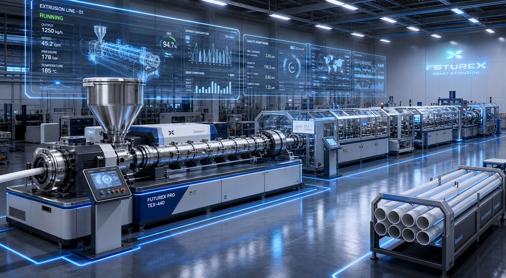
Screw geometry, barrel metallurgy, and process parameter discipline form the foundation of consistent pipe quality. But the twin screw extruders market is not standing still. Machine builders and component suppliers are introducing technologies that reshape what pipe manufacturers can expect from their lines — lower energy costs per kilogram, real-time quality visibility, and the ability to process materials that did not exist a decade ago. Staying competitive means understanding which of these advances deliver measurable returns and which are still maturing.
Energy-Efficient Drive Systems and Servo Motor Integration
The drive motor consumes 50 to 60% of the total energy in a twin screw extrusion line. That single fact explains why drive technology has become the highest-impact area for efficiency improvement. Traditional AC induction motors — even high-efficiency IE3 models — lose 5 to 10% of input energy as rotor heat and slip losses. The shift toward IE4 and IE5 permanent magnet synchronous motors (PMSM) eliminates rotor losses entirely, pushing motor efficiency to 97 to 98.5%.
What does that look like in practice? Consider a medium-sized PVC pipe line running a 75 kW extruder 24 hours a day, 300 days a year. At conventional motor efficiency, annual electricity consumption sits around 540,000 kWh. Upgrading to an IE5 PMSM drive can reduce that figure by 15 to 20%, saving roughly $10,000 to $14,000 per year at typical industrial electricity rates. Over a machine's 15-year service life, the cumulative savings often exceed the motor's premium cost by a factor of three or four.
Direct-drive configurations take this further by eliminating the gearbox entirely or replacing traditional gear trains with high-torque, low-speed motor designs. Every gear stage introduces friction losses — typically 2 to 5% per stage. Removing that mechanical interface not only recovers energy but also improves speed control precision. For pipe production, where even slight screw speed fluctuations translate into wall thickness variation, that precision matters. Paired with vector-control variable frequency drives (VFDs) capable of speed regulation within ±0.1 RPM, these systems maintain dimensional consistency at a level that older drive architectures cannot match.
Modern VFDs also incorporate intelligent features like automatic torque optimization — reducing power draw when material viscosity drops due to ambient temperature changes — and regenerative braking that feeds energy back into the plant grid during screw deceleration. Even sleep-mode functionality, which idles the motor at minimal power during changeovers rather than running at full speed, contributes meaningful savings in batch-oriented pipe operations.
Smart Process Monitoring and Digital Controls
Imagine knowing that your pipe wall thickness is drifting 45 minutes before it crosses the reject threshold — and having the system adjust automatically to correct it. That is the promise of Industry 4.0 principles applied to pipe extrusion, and it is moving from concept to production-floor reality.
The foundation is sensor density. Modern plastic twin screw extruder lines embed melt pressure transducers at multiple barrel positions and the die, thermocouples mapping temperature across every zone, screw torque sensors tracking plasticizing load in real time, and motor current monitors that reveal subtle changes in material behavior. These data streams feed into digital control platforms that display live trends, trigger alarms on deviation, and — increasingly — execute predictive adjustments without operator intervention.
Cloud-based dashboards extend this visibility beyond the control room. Process engineers, quality managers, and maintenance planners can monitor line performance from anywhere with network access, comparing shift-to-shift efficiency, tracking OEE (Overall Equipment Effectiveness) decomposition, and identifying patterns that plant-level averages would hide. One documented case found that 70% of quality-related losses clustered within the first 45 minutes of each shift — a finding that led to a targeted pre-shift warm-up protocol recovering 4% of effective capacity.
Predictive maintenance is where the data delivers its highest return. Vibration signatures on gearbox bearings, gradual motor current increases suggesting screw wear, and temperature stratification indicating barrel heater degradation all generate early warning signals. Machine learning models trained on baseline behavior estimate remaining useful life for key components, allowing maintenance teams to schedule interventions during planned changeovers instead of accepting costly unplanned downtime. Condition monitoring algorithms even compare actual motor torque against theoretical demand to flag situations where screw and barrel wear has degraded energy transfer efficiency — the same silent performance erosion discussed in the troubleshooting and component selection sections of this article.
Much of this extruder technology is validated first on a laboratory twin screw extruder scale, where researchers test sensor integration, control algorithms, and digital twin models before deploying them on full-production pipe lines. These laboratory twin screw extruder platforms allow process engineers to simulate formulation changes, screw configurations, and control strategies in a controlled environment — reducing the risk and cost of implementing new monitoring systems on high-throughput equipment.
Higher-Output Designs and Material Versatility
Market demand for large-diameter infrastructure pipe — 400 mm and above for water transmission, sewer mains, and industrial applications — is pushing machine builders toward larger conical twin screw extruders with higher torque density and wider processing envelopes. These machines deliver throughputs that would have required multiple parallel lines a generation ago, consolidating production onto fewer, more efficient assets.
Material versatility is evolving in parallel. Regulatory pressure and sustainability commitments are driving pipe manufacturers to incorporate recycled PVC and bio-based polymers into their formulations. Recycled PVC introduces batch-to-batch variability in molecular weight, residual stabilizer content, and contaminant levels that stress the extruder's plasticizing and mixing capabilities. A twin screw plastic extruder with optimized screw geometry and robust process controls handles this variability far more reliably than older designs — but only if the barrel and screw components themselves maintain tight tolerances and appropriate metallurgy.
Here is a summary of the key trends reshaping the industry:
- IE4/IE5 permanent magnet motors delivering 97-98.5% efficiency and reducing energy cost per kilogram of pipe produced
- Direct-drive and gearbox-less configurations eliminating mechanical losses and improving speed control precision for tighter dimensional tolerances
- Real-time IoT sensor networks capturing melt pressure, temperature, torque, and vibration data for cloud-based monitoring and predictive analytics
- Predictive maintenance algorithms estimating remaining component life and scheduling interventions before unplanned failures occur
- OEE tracking and digital dashboards enabling data-driven shift management, benchmarking, and continuous improvement
- Larger-diameter conical extruders with higher torque density for large-pipe production on single-line configurations
- Recycled PVC and bio-polymer processing capability supported by wider processing envelopes and advanced mixing designs
- CFD-optimized screw geometry reducing specific mechanical energy by 10-15% without compromising mixing or gelation quality
Keeping pace with these advancements starts with foundational components. The most sophisticated servo drive and digital control platform cannot compensate for a worn barrel that leaks pressure, creates hot spots, and degrades melt homogeneity. Suppliers like NANHAIYA, who specialize in precision-manufactured conical twin screw barrels for PVC pipe, profile, sheet, and WPC extrusion, help manufacturers maintain the plasticizing quality that these newer, higher-output machines demand. Whether you are upgrading an existing line with energy-efficient drives or commissioning a next-generation extruder designed for recycled material processing, ensuring that your barrel and screw components deliver tight clearances, optimized taper geometry, and application-matched metallurgy is what translates machine-level innovation into consistent pipe quality on the production floor.
Frequently Asked Questions About Twin Screw Pipe Extruders
1. What is the difference between a conical and parallel twin screw extruder for pipe production?
A conical twin screw extruder uses tapered screws that narrow from feed to discharge, providing gentle progressive compression ideal for thermally sensitive PVC dry blend. It operates in counter-rotating mode at lower RPM (30-150), generating low shear and high die pressure — perfect for standard rigid PVC pipe. A parallel twin screw extruder maintains constant screw diameter and typically co-rotates at higher speeds (200-900+ RPM), delivering intensive distributive mixing suited for specialty applications like WPC pipe, heavily mineral-filled PP pipes, or inline compounding. Choosing between them depends primarily on your material type and the mixing intensity your formulation demands.
2. Why do PVC pipe manufacturers prefer twin screw extruders over single screw models?
PVC pipe production typically starts with dry blend powder rather than pre-compounded pellets, requiring the extruder to perform in-line plasticizing. Twin screw extruders handle this through forced displacement conveying that moves powder reliably regardless of friction conditions, whereas single screw machines depend on friction-based transport that struggles with low-density PVC powder. The self-wiping intermeshing action of twin screws also prevents material stagnation critical for heat-sensitive PVC, delivers superior additive dispersion, and produces more stable melt pressure for tighter wall thickness tolerances. These advantages make twin screw extruders the industry standard for PVC pipe, which represents the largest segment of the global plastic pipe market.
3. How do you troubleshoot wall thickness variation in twin screw pipe extrusion?
Wall thickness variation typically originates from three sources: inconsistent melt pressure from the extruder (caused by worn screw flights allowing backflow, feeding inconsistencies, or improper screw speed), uneven die gap settings (misaligned mandrel centering bolts), or haul-off speed instability. Start by checking extruder screw and barrel clearances for wear, then calibrate your gravimetric feeder for consistent mass flow, and verify haul-off drive synchronization. If the variation is circumferential (one side thicker), focus on die centering. If it appears as periodic waves along the pipe length, investigate melt pressure surging and haul-off speed fluctuation.
4. When should you replace the screw and barrel on a twin screw pipe extruder?
A common industry guideline flags replacement when flight clearance reaches four times the original tolerance — for example, when a gap originally machined to 0.2 mm has worn to 0.8 mm. However, for PVC pipe production, many operators set tighter thresholds due to PVC's shear sensitivity. Warning signs include gradually declining throughput at the same RPM, rising energy consumption, increasing scrap rates, surface roughness, discoloration, and wall thickness instability that process adjustments cannot resolve. Standard nitrided steel barrels typically last 12-18 months under normal PVC conditions, while bimetallic-lined barrels extend service life to two to three years. Specialist suppliers like NANHAIYA offer custom conical twin screw barrels engineered for specific formulations, helping restore and even improve original performance.
5. What process parameters most affect PVC pipe quality in twin screw extrusion?
Five interdependent parameters control PVC pipe quality: barrel temperature profile (governs gelation level, affecting impact strength and surface finish), screw speed (determines shear rate, residence time, and viscous heat generation), melt temperature at the die (influences molecular integrity, color, and pressure rating), melt pressure stability (controls wall thickness uniformity and diameter accuracy), and back pressure (affects mixing completeness and density uniformity). These parameters interact — increasing screw speed raises melt temperature through viscous dissipation, which shifts barrel zone requirements and alters the back pressure needed for adequate homogeneity. The best-performing pipe lines treat them as an integrated system rather than isolated settings.
Written by
Nanhaiya Technical Team
Zhoushan Nanhaiya Plastic Machinery Co., Ltd.
The Nanhaiya technical team supports screw and barrel manufacturing projects through application review, technical communication, custom manufacturing coordination, and production and quality control.
Discuss Your Application
Related Articles
More insights on screw barrel technology and plastics processing.

What Nobody Tells You About Screw Barrel For Plastic Machine Design
Oct 10, 2026
Learn how screw barrel for plastic machine design affects melt quality, throughput, and wear life. Covers geometry, resin matching, troubleshooting, and sourcing.
Read Article
Single Screw Extruder for Sheet: Stop Guessing, Start Specifying
Oct 9, 2026
Learn how to specify a single screw extruder for sheet production. Covers screw geometry, resin-specific processing, troubleshooting, and maintenance best practices.
Read Article
PE Pipe Extruder Machine: What Datasheets Won't Tell You
Oct 9, 2026
Learn how a PE pipe extruder machine works, key specs explained, material grade selection, maintenance tips, and buyer guidance beyond the datasheet.
Read ArticleLooking for something else?
Search by material, symptom or product and jump straight to the relevant page.
These are navigation suggestions based on keyword matching — not a quotation, not a delivery commitment, and not a substitute for engineering review. Final specification is confirmed by our engineers against your drawings and processed material.
Need help with screw barrel selection?
Share your machine model, processed material and application. Our team can help with pricing and technical support.