

What Twin Screw Extruders Are and Why They Dominate Polymer Processing
Imagine trying to blend a handful of different powders, pellets, and liquid additives into a perfectly uniform molten stream—continuously, at hundreds of kilograms per hour—while controlling temperature, shear, and residence time down to narrow tolerances. That is the challenge twin screw extruders were built to solve, and it is precisely why they have become the backbone of modern polymer compounding.
What Is a Twin Screw Extruder
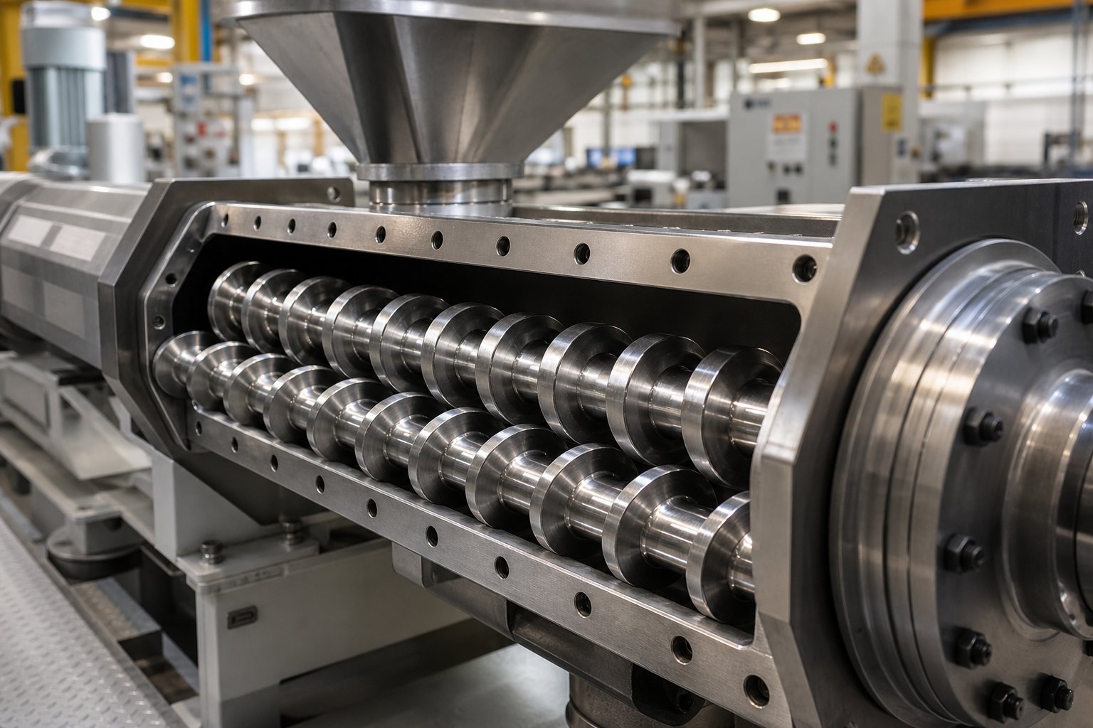
A twin screw extruder is a processing machine that uses two intermeshing, co-rotating or counter-rotating screws inside a heated barrel to continuously convey, melt, mix, and shape polymeric materials. Its modular screw and barrel design enables precise control over shear intensity, temperature, and residence time, making it the preferred platform for compounding, reactive extrusion, devolatilization, and high-performance mixing.
What makes this machine so versatile? The answer lies in the range of functional capabilities packed into a single processing line. Each zone along the barrel performs a distinct role, and you can reconfigure screw elements to prioritize any one of these functions:
- Conveying — Forward-pitch screw elements transport raw material from the feed throat toward the die, controlling fill level and throughput.
- Melting — A combination of barrel heat and mechanical shear energy converts solid pellets or powder into a homogeneous melt.
- Dispersive mixing — High-shear kneading zones break down agglomerates, pigment clusters, or filler bundles into their primary particle size.
- Distributive mixing — Specialized elements spread those dispersed particles evenly throughout the polymer matrix.
- Devolatilization — Vent ports paired with melt seals allow moisture, residual monomers, or solvents to escape under vacuum or atmospheric pressure.
- Pumping — Pressure-building elements at the downstream end push the finished melt through a die or into downstream pelletizing equipment.
A single screw extruder can melt and pump, but it relies almost entirely on friction between the material and the barrel wall to generate forward motion. Twin screw extruders, by contrast, use the intermeshing geometry of their two screws to create positive conveying and intense mixing that a single screw simply cannot replicate through channel depth changes alone. This distinction matters most when you need to incorporate fillers, blend immiscible polymers, or run reactive chemistries at production scale.
Why Twin Screw Extruders Are the Industry Standard for Compounding
The real advantage comes down to process-engineering control. In a twin screw system, throughput is governed by the gravimetric feeder, screw speed controls shear input, and barrel zone temperatures manage thermal energy—each parameter adjusted independently. That decoupling gives process engineers a level of precision unavailable in simpler equipment, where changing one variable inevitably shifts another.
Here are the primary reasons twin screw extruders have become the standard across compounding, masterbatch production, and reactive processing:
- Superior mixing quality — Intermeshing screws generate both shear flow and elongational flow fields, producing thorough dispersive and distributive mixing in a single pass.
- Self-wiping action — In fully intermeshing designs, the screws continuously scrape material from each other's surfaces and the barrel wall, preventing stagnation, thermal degradation, and product cross-contamination during changeovers.
- Modular design flexibility — Screw elements and barrel sections can be rearranged to match new formulations or processing goals without purchasing a new machine.
- Narrow residence time distribution — Starve-fed operation and positive conveying minimize the spread of residence times, protecting heat-sensitive polymers from degradation.
- High process adaptability — Side feeders, liquid injection ports, and multiple vent zones can be added along the barrel to handle complex, multi-component formulations.
Whether you are a process engineer optimizing a compounding line or a procurement specialist evaluating capital equipment, understanding how twin screw configuration choices affect output quality is essential. The sections ahead break down co-rotating versus counter-rotating designs, screw element strategy, material-specific processing, and maintenance planning—the practical knowledge that separates reliable production from costly trial and error.
Co-Rotating vs Counter-Rotating Twin Screw Extruders Compared
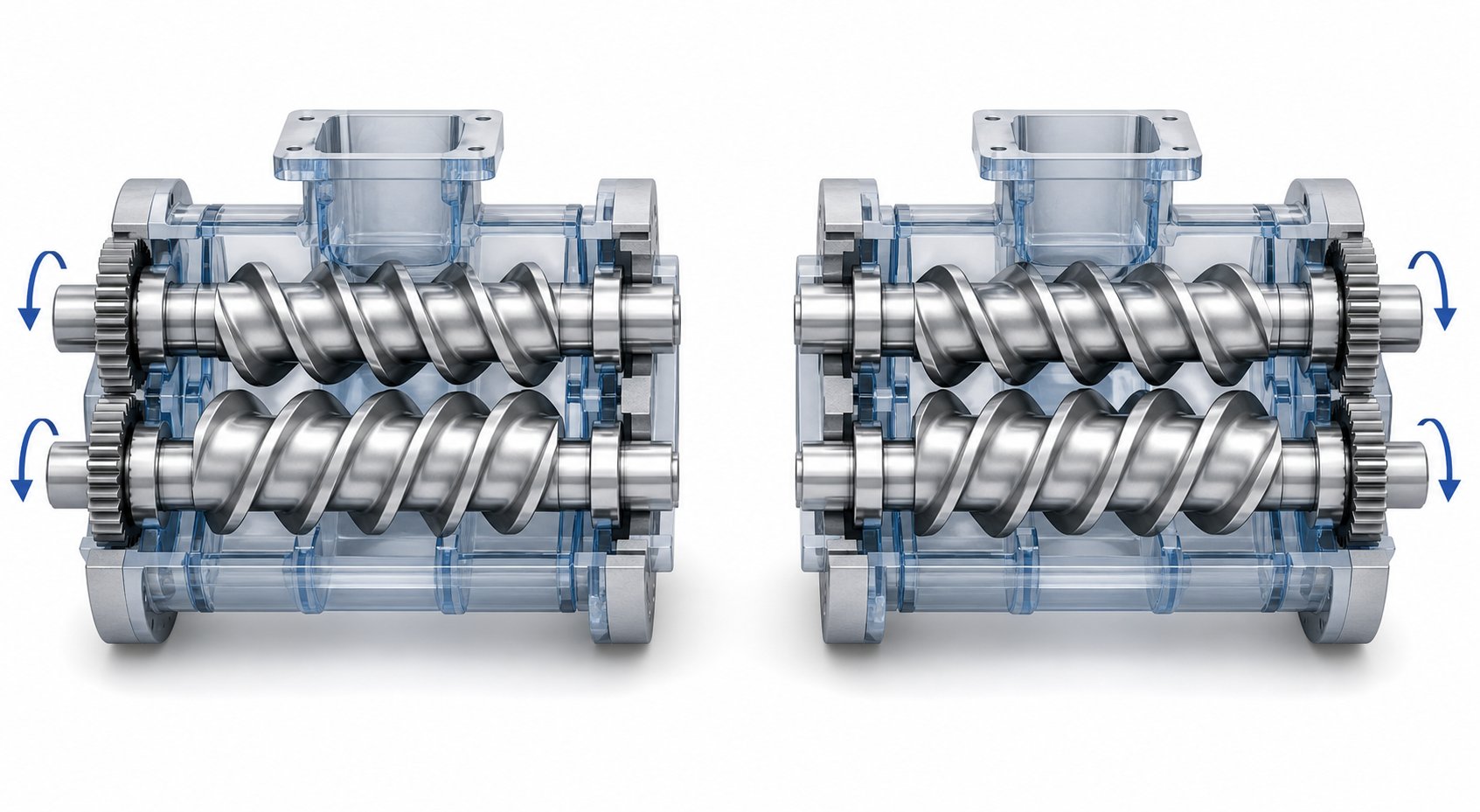
Every twin screw extruder falls into one of two families based on a single, seemingly simple variable: do the screws turn the same way or in opposite directions? That distinction, however, reshapes everything—flow patterns, shear intensity, residence time behavior, and ultimately, which applications each machine handles best. Choosing between a co-rotating and counter-rotating twin screw extruder is less about which is "better" and more about which matches your processing goal.
Co-Rotating Intermeshing Twin Screw Extruders
In a co-rotating twin screw extruder, both screws turn in the same direction inside a fully intermeshing geometry. Picture the material path: as the flights of one screw overlap with those of the other, polymer is forcibly handed off from screw to screw, tracing a continuous figure-eight flow pattern through the barrel. This constant transfer between screws produces two critical effects.
First, the relative motion at the intermeshing zone generates intense shear fields that accelerate melting and deliver thorough dispersive and distributive mixing. Second, the self-wiping action—where each screw scrapes material from the other's surface—virtually eliminates dead zones. Stagnant material means thermal degradation, and self-wiping keeps the residence time distribution narrow enough to safely process heat-sensitive formulations and run reactive extrusion chemistries.
These characteristics explain why co-rotating parallel twin screw extruder configurations dominate masterbatch production, engineering plastics compounding, nanocomposite dispersion, and devolatilization operations. Their modular screw design also allows processors to rearrange kneading blocks, conveying elements, and mixing discs in virtually unlimited combinations, tuning shear intensity zone by zone along the barrel.
Counter-Rotating Intermeshing Twin Screw Extruders
Flip one screw's rotation direction and the processing physics change dramatically. In a counter-rotating configuration, the screws draw material inward at the intermeshing zone and compress it forward through approximately closed C-shaped chambers. This geometry acts as a positive displacement pump—output volume depends on screw rotation rather than frictional drag, and backflow is inherently restricted.
Instead of the high-shear transfer seen in co-rotating designs, counter-rotating screws create a calendering effect at the nip point. Material undergoes repeated compressive and elongational deformation under relatively gentle conditions, which keeps shear heating low. That thermal advantage is exactly why counter-rotating machines became the industry standard for rigid PVC pipe, sheet, and profile extrusion—materials where even modest overheating triggers degradation and discoloration.
Counter-rotating extruders come in two geometric sub-types. A parallel twin screw extruder variant uses cylindrical screws of equal diameter along their full length, offering a longer L/D ratio that benefits high-filler PVC compounds needing extended plasticization time. A conical twin screw extruder, by contrast, tapers the screws from a large feed diameter down to a smaller discharge diameter. The conical geometry provides high intake volume for bulky dry-blend feeds while building substantial discharge pressure in a compact footprint—making it popular for medium-output PVC pipe and profile lines.
How to Choose Between Co-Rotating and Counter-Rotating Configurations
Rather than memorizing feature lists, think about what your process demands. Need aggressive filler dispersion and the flexibility to reformulate weekly? Co-rotating wins. Need gentle, thermally stable conveying of a shear-sensitive compound directly into a profile die? Counter-rotating is the better fit. The table below maps the most important decision criteria side by side.
| Criterion | Co-Rotating Intermeshing | Counter-Rotating Intermeshing |
|---|---|---|
| Shear Intensity | High — strong shear in intermeshing zone and at barrel wall | Low to moderate — gentle calendering and elongational flow |
| Self-Wiping Capability | Excellent — continuous wiping minimizes stagnation | Limited — C-chamber design restricts cross-screw flow |
| Pressure Generation | Moderate — may require gear pump assist for tight die tolerances | High — positive displacement delivers stable die pressure |
| Residence Time Distribution | Narrow — ideal for heat-sensitive and reactive processing | Broader — acceptable for stable polymers, beneficial for longer reaction times |
| Typical Applications | Compounding, masterbatch, nanocomposites, reactive extrusion, devolatilization | PVC pipe and profile, sheet extrusion, cable coating, direct forming |
| Throughput Range | Wide — scalable from lab (kg/h) to production (tons/h) | Moderate — optimized for steady-state profile and pipe output |
| Screw Speed Range | High (up to 600–1,200 rpm on modern machines) | Low to moderate (typically 10–60 rpm) |
| Process Flexibility | Very high — modular elements allow rapid reconfiguration | Moderate — geometry constrained by tight intermeshing clearances |
The decision ultimately hinges on your material's thermal sensitivity and the type of mixing you need. For multi-component compounding where dispersive and distributive quality drive end-product performance, co-rotating designs give you the shear intensity and modular flexibility to dial in results. For direct extrusion of thermally fragile compounds—particularly PVC—where stable pressure and low-shear conveying protect product integrity, counter-rotating machines remain unmatched.
Configuration choice, however, is only half the equation. The real performance tuning happens at the element level—where the specific arrangement of conveying flights, kneading blocks, and mixing discs along the screw shaft creates processing profiles tailored to each application.
Twin Screw vs Single Screw Extruder Performance Breakdown
Co-rotating and counter-rotating designs represent different philosophies within the twin screw family—but how do both compare against the single screw extruder that still dominates many production floors? The distinction goes deeper than screw count. Fundamental differences in feeding strategy, melt conveyance, and mixing mechanics determine which platform delivers better results for a given application.
Fundamental Design and Operating Differences
The most consequential engineering difference is how each machine controls throughput. A single screw extruder is typically flood-fed: material fills the hopper, gravity keeps the feed zone packed, and the screw's drag-flow capacity dictates output rate. Change the screw speed and you simultaneously change both throughput and shear input—they are coupled variables. Research into flood-fed versus starve-fed screw extrusion confirms that this coupling limits the operator's ability to independently optimize output and energy consumption on single screw platforms.
A double screw extruder machine, by contrast, operates in starve-fed mode. A gravimetric feeder meters material into the barrel at a controlled rate, and the screws transport it forward regardless of fill level. This decoupling means you can raise screw speed to increase shear without pushing more material through the system—or reduce speed to lower mechanical energy input without sacrificing throughput. That independence is essential for processing temperature-sensitive compounds, where a narrow window separates adequate mixing from thermal degradation.
Intermeshing geometry adds another layer of capability. In a twin screw system, the overlap between the two flights forces material to transfer from one screw channel to the other repeatedly. As extrusion expert Jim Frankland explains, this screw-to-screw transfer enables full-channel mixing while applying high shear to only a small fraction of the melt at any given moment—something a single screw simply cannot replicate. Single screw designs rely on the velocity gradient between the barrel wall and the screw root, which creates stratified flow and leaves some portion of the channel poorly mixed. Adding restrictive mixing elements helps, but each restriction drops output pressure and raises melt temperature, compounding the problem.
Residence time distribution follows directly from these mechanics. Starve-fed twin screw systems keep material moving through well-defined processing zones with minimal spread in residence time. Flood-fed single screw extruders, with their fully packed channels and velocity stratification, produce a broader residence time distribution—acceptable for stable resins but risky for heat-sensitive or reactive formulations.
Performance Comparison Across Key Processing Criteria
The table below distills these engineering differences into a side-by-side comparison you can reference when evaluating which screw extruder platform fits your processing requirements.
| Processing Criterion | Twin Screw Extruder | Single Screw Extruder |
|---|---|---|
| Dispersive Mixing | Excellent — intermeshing and kneading blocks deliver high-shear dispersion of agglomerates and pigments | Limited — requires restrictive mixers (e.g., Maddock) that reduce output and raise melt temperature |
| Distributive Mixing | Excellent — screw-to-screw transfer repeatedly redistributes melt across full channel volume | Moderate — flow stratification leaves portions of the channel undermixed |
| Throughput Flexibility | High — feeder-controlled, independent of screw speed | Low — output is coupled to screw speed and channel geometry |
| Heat Generation Control | Precise — shear input adjustable via screw speed without changing throughput | Limited — screw speed changes alter both shear and output simultaneously |
| Material Versatility | Very high — handles blends, filled compounds, reactive systems, and recycled feedstocks | Moderate — best for single-resin processing of pre-compounded material |
| Venting Efficiency | High — multiple vent zones with melt seals enable deep devolatilization | Low to moderate — limited vent positions and less effective melt sealing |
| Capital Cost | Higher — complex gearbox, modular screw and barrel components | Lower — simpler drive train and fixed-geometry screw |
| Operating Cost | Moderate — higher specific energy but offset by single-pass processing | Lower for simple applications — energy-efficient when mixing demands are minimal |
| Maintenance Complexity | Higher — tight intermeshing clearances require regular wear monitoring of modular elements | Lower — robust design with fewer wear-sensitive components |
| Typical Applications | Compounding, masterbatch, reactive extrusion, devolatilization, recycling of mixed streams | Film and sheet extrusion, pipe extrusion of pre-compounded resin, simple pelletizing |
When a Single Screw Extruder Is the Better Choice
Not every operation needs the mixing firepower a double screw extruder provides. When you are melting and pumping a single, pre-compounded resin into a sheet die or blown film line, the simplicity of a single screw platform is a genuine advantage—not a compromise.
Consider these scenarios where a single screw extruder outperforms or matches its twin screw counterpart on a cost-to-performance basis:
- Film and sheet extrusion of homogeneous resins — Pre-compounded polyethylene or polypropylene pellets need efficient melting and stable pressure delivery, not intensive mixing. A single screw extruder handles this at lower capital and operating cost.
- Simple pipe extrusion — HDPE or PEX pipe lines benefit from the steady, high-pressure pumping that a well-designed single screw provides, with minimal shear-induced orientation issues.
- Lower capital budgets for straightforward applications — For processors running one or two stable formulations with clean, consistent feedstock, the additional investment in a twin screw system may not deliver a meaningful quality return.
- High-volume single-resin pelletizing — Reprocessing clean post-industrial scrap of a single polymer type often requires only melting, filtration, and pelletizing—tasks where single screw machines offer reliable throughput at lower energy cost per kilogram.
The honest takeaway? These two platforms complement each other rather than compete. A compounding operation may rely on twin screw technology to produce specialty pellets, while the downstream converter runs those same pellets through a single screw extruder for film or profile production. Matching the machine to the task—rather than defaulting to the most capable option—keeps both quality and economics in check.
Of course, selecting the right platform is only the starting point. The real performance lever inside any twin screw system is the specific arrangement of elements along the screw shaft—conveying flights, kneading blocks, mixing discs, and reverse elements—each sequenced to create a processing profile tailored to the polymer and additive package at hand.
Screw Element Configuration Strategy for Optimal Processing
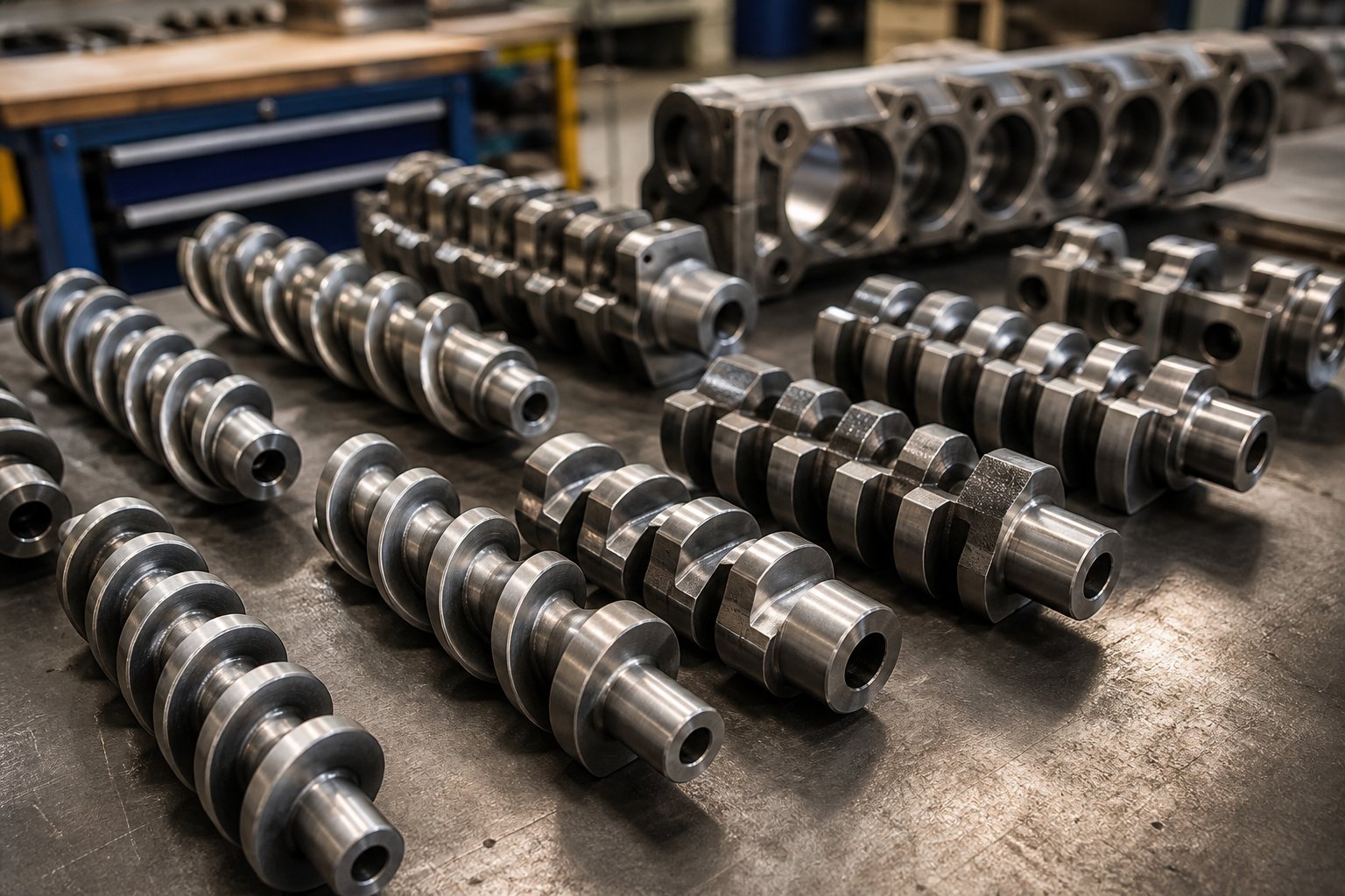
Think of each extruder screw not as a single, fixed piece of hardware but as a sentence built from interchangeable words. Swap a few words—or rearrange their order—and the meaning changes entirely. That is exactly how modular screw elements work on a twin screw extruder: the specific types you select and the sequence you mount them on the splined shaft determine whether your process delivers flawless dispersion or fighting torque alarms. Mastering this element-level configuration is arguably the single most impactful skill a process engineer can develop, because it lets you reshape processing behavior without purchasing new equipment.
Types of Screw Elements and Their Functions
Every plastic extruder screw profile is assembled from a handful of element families, each engineered for a distinct processing role. You'll encounter them in roughly the same functional sequence along the barrel, from the feed throat to the die. Here is how they break down:
- Conveying elements (forward pitch) — These are the workhorses responsible for moving material downstream. Deep-flighted conveying elements pull raw feed from the hopper, transport partially melted material through transition zones, and push fully molten polymer toward the die. Pitch matters: a large-pitch element moves material quickly with minimal fill, while a short-pitch element slows transport, raises local fill level, and begins building pressure. As NC State Extension research explains, deeper channel flights enable efficient conveyance without imparting significant shear—ideal for solids transport zones where you want material to advance before melting begins.
- Kneading blocks (narrow and wide disc configurations) — These are the heart of mixing in any twin screw system. A kneading block consists of multiple lobed discs stacked at staggered angular offsets—typically 30°, 45°, 60°, or 90°. The stagger angle is the primary control variable. Narrow-disc kneading elements at moderate stagger angles (30°–45°) favor distributive mixing, splitting and recombining the melt stream to spread additives uniformly without excessive shear. Wide-disc kneading blocks at higher stagger angles (60°–90°) apply intense shear stress for dispersive mixing, physically breaking down pigment agglomerates, filler clusters, or immiscible polymer domains. Forward-staggered kneading elements maintain some conveying action, while neutral (90°) kneading blocks provide no forward conveyance at all—they force the material to dwell, maximizing energy input and residence time in that zone.
- Mixing elements (gear, tooth, and turbine types) — When you need thorough blending without the shear intensity of kneading blocks, specialized mixing elements fill the gap. Toothed mixing elements, for example, generate repeated flow splitting and recombination as material passes through rows of gear-like teeth. This geometry delivers excellent distributive mixing while strictly limiting melt temperature rise—critical for color masterbatch homogenization or gentle blending of polymer alloys. Turbine-type elements work similarly, using radial passages to redirect flow across the channel without creating the localized shear peaks that kneading blocks produce.
- Reverse elements (left-handed conveying and reverse kneading) — Imagine placing a screw element that pushes material backward into a forward-conveying stream. The upstream material must build enough pressure to overcome that resistance before it can advance. This deliberate restriction creates a fully filled melt seal—an essential feature for two purposes. First, reverse elements upstream of vent ports prevent air or vacuum from traveling backward along the barrel, enabling effective devolatilization. Second, they create high-pressure zones that improve melt homogeneity by forcing the polymer through a constriction. The trade-off? Every reverse element raises local residence time and mechanical energy input, so placement must be precise.
How Element Sequence Creates Processing Profiles
Knowing what each element does individually is necessary—but the real engineering insight lies in understanding how their sequence creates a complete processing profile. Two plastic extrusion screw configurations using identical element inventories can produce radically different outcomes simply by rearranging the order along the shaft.
Screw design always follows the process—never the other way around. Define the unit operations your material requires (melting, mixing, venting, pressure buildup), then select and sequence elements to deliver each operation at the right position along the barrel.
Consider two contrasting examples to see this principle in action:
Example 1: High-filler compounding profile. A calcium carbonate or talc-filled polypropylene compound needs aggressive filler dispersion followed by homogenization. The screw profile begins with large-pitch conveying elements in the feed zone to handle bulky powder-pellet mixtures. After sufficient conveying length for initial melting, a bank of wide-disc kneading blocks at 60° stagger delivers the dispersive shear needed to break filler agglomerates. Following that, narrow kneading elements or toothed mixing elements redistribute the filler uniformly throughout the melt. A short reverse element upstream of the vent port creates a melt seal, allowing atmospheric or vacuum venting to strip entrapped air. Finally, forward conveying elements with decreasing pitch build the die pressure needed for strand pelletizing.
Example 2: Devolatilization-focused profile. A polymer requiring deep moisture or solvent removal—common in recycling and reactive extrusion—demands a different architecture entirely. Here, the twin screws are configured with moderate kneading zones early in the barrel to achieve a complete, homogeneous melt. The key innovation is what comes next: a reverse element creates a full melt seal, immediately followed by deep-flighted conveying elements under a vacuum vent port. Those deep flights maximize exposed melt surface area, allowing volatiles to escape efficiently. In processes needing multiple stages of devolatilization, this seal-vent-convey sequence repeats further downstream, each stage pulling residual volatiles to progressively lower levels. Pressure-building elements at the discharge end push the cleaned melt through the die.
Notice how the same element families—conveying, kneading, reverse—appear in both profiles, yet the arrangement and emphasis are completely different. The compounding profile prioritizes intensive mixing zones, while the devolatilization profile prioritizes melt sealing and surface renewal at vent locations. This is why experienced process engineers treat the screw configuration as the most powerful optimization tool available before adjusting operating parameters like speed or temperature.
Balancing Mixing Intensity with Material Residence Time
Here is where the trade-offs get real. Every kneading block and reverse element that improves mixing quality also adds mechanical energy and extends the time material spends inside the barrel. For robust polymers like polypropylene filled with mineral additives, that extra energy is tolerable and often beneficial. For shear-sensitive or thermally fragile materials—think PVC, biodegradable PLA, or thermoplastic elastomers—the same configuration could trigger chain scission, discoloration, or loss of elastic properties.
Three interacting variables govern this balance:
- Fill ratio — In starve-fed operation, the degree of barrel fill at any point depends on the relationship between feeder rate and local screw geometry. A partially filled barrel transfers less energy to the melt than a fully packed one. Adjusting throughput relative to screw speed shifts fill ratio and, with it, the intensity of every kneading zone.
- Screw speed — Higher speed increases the shear rate in kneading blocks and reduces total residence time as material moves faster through conveying zones. For an aggressive screw profile, running at higher speed may actually reduce degradation risk by shortening thermal exposure—provided the instantaneous shear stress does not exceed the polymer's tolerance. Research at TU Dortmund University demonstrated that increasing throughput at constant specific feed load narrows the residence time distribution, reducing overall distributive mixing capacity but also limiting thermal stress on the processed material.
- Element configuration — The number, width, and stagger angle of kneading blocks determine local shear intensity. Replacing a 90° neutral kneading block with a 45° forward kneading element at the same position reduces shear and residence time in that zone while maintaining some mixing action. Similarly, shortening a reverse element from 20 mm to 10 mm reduces the melt seal's restrictive effect, lowering upstream pressure and energy input at the cost of a slightly less effective vent seal.
These three variables function as a system, not as independent dials. Adjusting one inevitably shifts the operating envelope of the others. A practical approach? Start with a moderately aggressive configuration, run the process at target throughput and speed, then measure specific mechanical energy (SME) and melt temperature. If melt temperature runs too high or product shows signs of degradation, the first response should be to swap aggressive kneading blocks for gentler alternatives or reduce their total length—not simply to cut screw speed, which may starve downstream zones and create new problems.
The principle that connects all of this is straightforward: the twin screws impose a processing history on every gram of polymer that passes through the barrel. Element configuration determines the type of processing at each position, while operating parameters determine the intensity. Getting both right requires thinking about the barrel as a series of integrated zones—and that naturally leads to the next critical hardware decision: how different barrel sections themselves are designed, arranged, and maintained to support the screw profile above them.
Modular Barrel Design and Section Configuration
Screw elements define what happens to the polymer at each position along the shaft—but the barrel surrounding those elements defines where material enters, where volatiles escape, and how thermal energy is managed zone by zone. A perfectly optimized screw profile mounted inside an improperly configured barrel is like a precision engine bolted to the wrong chassis. Understanding how different twin screw barrel sections work together is essential to building an extruder system that actually delivers on the promise of modular processing.
Barrel Section Types and Their Roles in the Processing Line
Modern parallel and conical twin screw extruders use segmented barrels—typically ten to twelve individual sections bolted together in sequence, each independently heated and cooled. The arrangement of these sections mirrors the screw element layout to create integrated processing zones. Here are the four primary barrel types you will encounter:
- Feed barrels (open-top) — Positioned at the upstream end of the barrel assembly, these sections feature a large opening at the top through which solid pellets, powder, or flake material enters the screw channel. Low bulk density powders can trap air during feeding, so some configurations place two open barrels in sequence: one for material intake and the other upstream as a rear vent, allowing displaced air to escape without obstructing the feed throat.
- Closed barrels — The most common section type, fully enclosing the figure-eight bore on all sides. Closed barrels handle the core processing functions—solid conveying, melting, and intensive mixing—where material must remain fully contained. Each closed section carries its own heating elements and cooling channels, giving operators precise temperature control across every zone. When you need to add liquid additives, a variation with a small threaded injection port at the top connects to a needle valve and plunger pump for metered liquid delivery.
- Vented barrels — These sections include an atmospheric or vacuum port above the screw bore, positioned where screw elements create an exposed, partially filled melt surface. Atmospheric vents release trapped air or light volatiles, while vacuum ports connected to a pump strip residual moisture, monomers, or solvents from the melt. Placement is critical: vented barrels typically sit in the second or third section upstream of the die, with a melt-sealed zone created by reverse screw elements immediately upstream to prevent molten polymer from flowing back into the vent opening.
- Side-feed barrels — These sections feature a secondary eight-shaped opening on the barrel's side wall, connecting directly to a side-stuffer extruder. Downstream addition of fillers, glass fibers, or secondary polymer streams through side-feed barrels protects fragile additives from excessive shear exposure in the primary melting zone. A compact combination design integrates a small upstream vent directly into the side-feed barrel section, letting displaced air escape without requiring an additional open barrel segment.
The sequence matters as much as the selection. A typical compounding line starts with a feed barrel, followed by several closed barrels covering the melting and mixing zones, a side-feed barrel for downstream filler addition, more closed sections for homogenization, a vented barrel for devolatilization, and a final closed barrel for pressure buildup before the die. Rearranging these sections—moving a vent upstream, adding a second side-feed position—reshapes the entire processing profile without altering the screw elements themselves.
Barrel Metallurgy and Liner Technology for Wear Resistance
Every extruder screw and barrel set operates under constant abrasive, thermal, and sometimes corrosive stress. The metallurgy you choose for the barrel liner determines how long the bore maintains tight clearances with the screw flights—and tight clearances are what keep mixing efficiency high and energy waste low. Selecting the wrong liner material for your application is one of the fastest ways to drive up maintenance costs and degrade product quality.
Barrel material options fall along a spectrum from economical to premium, each engineered for specific processing demands:
- Nitrided steel (38CrMoAl) — The baseline choice for general-purpose compounding. Nitriding produces a hard surface layer (HV 900+) over a tough core, providing adequate wear resistance for unfilled or lightly filled polymer processing at a reasonable cost. Corrosion resistance is moderate, making this a poor fit for fluoropolymers or chemically aggressive formulations.
- Bimetallic liners (iron-based or nickel-based alloys) — When processing abrasive fillers like calcium carbonate, talc, or glass fiber, standard nitrided barrels wear out rapidly. Bimetallic barrel liners—centrifugally cast alloys such as iron-chromium-nickel carbide or high-chromium powder alloys—deliver hardness levels of HRC 60–64 and dramatically extend barrel life. These liners are the industry standard for high-filler compounding and masterbatch production where abrasive wear is the dominant failure mode.
- Corrosion-resistant alloys (HaC, 316L stainless steel) — Chemically aggressive polymers like fluoroplastics attack conventional steel barrels from the inside out. Nickel-based HaC alloy barrels provide superior corrosion resistance for these demanding applications. For food-contact or pharmaceutical extrusion, 316L stainless steel barrels offer both corrosion protection and the cleanability required by regulatory standards.
- Powder metallurgy (PM/HIP) liners — At the top of the performance hierarchy, hot isostatic pressed powder metallurgy liners combine extreme wear resistance with excellent corrosion protection. These are specified for the most demanding environments—high glass-fiber loadings, corrosive polymer chemistries, or extended-run operations where unplanned downtime carries steep financial penalties.
The relationship between liner selection and service life is not linear. A bimetallic barrel extruder liner processing 40% glass-fiber-reinforced nylon might last 5,000–8,000 operating hours, while the same barrel running unfilled polypropylene could exceed 20,000 hours. Material-specific wear data from your operation—or from your barrel supplier—should guide replacement planning rather than fixed calendar intervals.
For operations running parallel twin screw extruders in compounding, masterbatch, recycling, or pelletizing applications, sourcing replacement barrels from a supplier with deep expertise in high-wear configurations makes a measurable difference in uptime. NANHAIYA's parallel twin screw barrel line, for example, supports custom and standard replacement barrels engineered for these demanding processing environments—an option worth evaluating when your current barrel bore measurements start drifting beyond tolerance.
Barrel metallurgy, section arrangement, and screw element configuration form three interconnected layers of the same extruder system design. Get all three right and the machine runs predictably for thousands of hours. But the hardware only performs as intended when the process parameters—temperatures, screw speed, feed rate—are matched to the specific polymer flowing through it. Different polymer families impose very different demands on that hardware, and understanding those material-specific requirements is where processing expertise separates consistent production from trial-and-error frustration.
Material-Specific Processing on Twin Screw Extruders
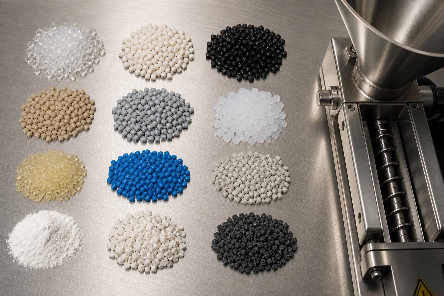
A perfectly configured screw profile and barrel layout will still produce mediocre results if the processing parameters ignore the polymer's own behavior. Every resin family brings a unique combination of melt viscosity, thermal stability, moisture sensitivity, and shear tolerance to the barrel—and each of these properties dictates how you should set temperatures, arrange kneading zones, and manage residence time. Treating the extruder for polymer processing as a one-size-fits-all machine is the single most common mistake that separates inconsistent output from production-grade compounding.
What follows is a material-first guide: start with the polymer, then work backward to the machine settings.
Polyolefin and Commodity Resin Compounding
Polyethylene (PE) and polypropylene (PP) are the backbone of commodity compounding—and for good reason. They offer wide processing windows, tolerate moderate shear without significant chain degradation, and melt at relatively low temperatures (120–170 °C for PE, 160–230 °C for PP). That forgiveness, however, can mask suboptimal setups that quietly reduce filler dispersion quality or introduce thermal inconsistencies.
When running a compounding twin screw extruder for polyolefin-based formulations, keep these processing considerations front and center:
- Filler incorporation (CaCO3, talc, BaSO4) — Mineral fillers at 20–70% loading demand dispersive kneading zones strong enough to break agglomerates, but not so aggressive that filler particles fracture into sub-micron fines that increase melt viscosity unpredictably. A typical approach places 60° stagger kneading blocks immediately after the melting zone, followed by toothed distributive mixing elements to spread the filler uniformly. Side-feeding abrasive fillers downstream of the primary melting zone protects the feed-section barrel liner from accelerated wear.
- Color masterbatch production — Pigment dispersion quality directly determines whether downstream converters see color streaks or clean, uniform tint. Narrow-disc kneading blocks at 45°–60° stagger deliver the shear stress needed to rupture pigment agglomerates, while a subsequent distributive mixing section ensures spatial uniformity. Screw speeds for masterbatch compounding often run higher than for filled compounds—sometimes above 500 rpm—because the short residence time at high speed prevents thermal yellowing in the carrier resin.
- Balancing shear and degradation — PP is particularly susceptible to thermo-oxidative chain scission, which manifests as a rising melt flow index over processing time. Keeping barrel temperatures in the lower half of the processing window and using forward-staggered kneading blocks rather than neutral or reverse blocks helps limit specific mechanical energy input while still achieving adequate mixing.
The key principle for polyolefins? They tolerate a wide range of configurations, but optimizing dispersion quality while minimizing unnecessary energy input is what separates good compounding from great compounding.
Engineering Plastics and High-Temperature Polymers
Step up from commodity resins to nylon (PA6, PA66), polybutylene terephthalate (PBT), polycarbonate (PC), or polyetheretherketone (PEEK), and the processing stakes rise sharply. Melt temperatures climb to 260–400 °C, molecular weight sensitivity to thermal history increases, and moisture becomes an active threat to product integrity.
Consider nylon 66 as a practical example. Its melting point sits near 260 °C, but it will absorb atmospheric moisture rapidly—sometimes reaching 0.3–0.4% moisture content within hours of exposure. Process that wet nylon through a polymer extruder without adequate drying or venting, and hydrolytic chain scission slashes molecular weight before the compound ever reaches the pelletizer. You will see the damage as reduced tensile strength and an uncontrolled spike in melt flow.
Processing strategies for engineering plastics revolve around three priorities:
- Moisture management — Pre-drying to below 0.02% moisture content is the first line of defense. But pre-drying alone may not be sufficient for high-performance applications. Vented barrel zones—especially vacuum venting at -0.08 MPa or deeper—strip residual moisture from the melt in-process. Position the vent port downstream of a reverse element melt seal, with deep-flighted conveying elements beneath the vacuum port to maximize surface renewal.
- Precise thermal control — Engineering resins have narrow processing windows where too-low temperatures produce unmelted gels and too-high temperatures trigger degradation. PC, for example, processes well between 280–310 °C but yellows rapidly above 320 °C. Independent barrel zone heating with PID control is non-negotiable. Monitor actual melt temperature at the die—not just barrel wall setpoint—because viscous shear heating in kneading zones can push true melt temperature 15–25 °C above barrel settings.
- Screw configuration emphasis — Engineering plastics often arrive as neat resins requiring glass fiber or mineral filler reinforcement. The screw profile should provide efficient melting in the first third of the barrel, side-feed the reinforcement downstream, and then use moderate kneading to wet out fibers without excessive breakage. For glass-fiber-reinforced nylon, keeping kneading blocks short and at moderate stagger angles (30°–45°) preserves average fiber length—a direct driver of final part strength.
Thermoplastic Elastomers and Biodegradable Polymers
If engineering plastics demand precision, thermoplastic elastomers (TPE, TPU) and biodegradable resins (PLA, PBAT, PBS) demand restraint. These materials punish aggressive processing with property losses that are invisible during extrusion but catastrophic in the finished product.
For TPE and TPU, the challenge is preserving elastic recovery. Excessive dispersive shear breaks down the soft-segment domains responsible for rubber-like behavior, converting a high-performance elastomer into a stiff, low-elongation compound. A compounding extruder configured for TPU should emphasize distributive mixing elements—toothed or gear-type—over aggressive kneading blocks. Where kneading blocks are necessary for additive dispersion, keep stagger angles at 30°–45° and limit block length. Barrel temperatures should track the material's processing window closely, typically 170–210 °C for standard TPU grades, and screw speeds should stay moderate to control both shear rate and melt temperature rise.
Biodegradable polymers present a different but equally demanding set of constraints. PLA begins to degrade meaningfully above 200 °C, with significant molecular weight reduction occurring above 220 °C. Moisture-driven hydrolysis compounds the problem: even 250 ppm of residual water can cause measurable chain scission during processing. PBS, PBAT, and starch-based polymers each add their own sensitivities—starch, for example, requires effective venting to release moisture generated during thermomechanical processing, while PBAT blends demand careful temperature profiling to melt all components without degrading any one of them.
The screw configuration for biodegradable resin compounding prioritizes short residence time and gentle mixing. Conveying-heavy profiles with limited, mild kneading zones minimize thermal exposure. Multiple vent ports—atmospheric or vacuum—positioned with upstream melt seals handle moisture removal. And because many biodegradable formulations are moisture-sensitive even after pelletizing, air-cooled strand pelletizing or die-face cutting avoids the water contact inherent in conventional strand bath systems.
The table below summarizes recommended processing parameters across these polymer families. Use it as a starting framework, and validate specific values against your material supplier's datasheets before committing to production settings.
| Polymer Family | Screw Configuration Emphasis | Barrel Temperature Range | Venting Requirements | Typical Downstream Setup |
|---|---|---|---|---|
| PE / PP (commodity polyolefins) | Balanced — moderate kneading for filler dispersion, distributive elements for homogenization | 180–240 °C | Atmospheric vent for air removal; vacuum vent for volatile-sensitive grades | Water-bath strand pelletizer or underwater pelletizer |
| PA (nylon 6, nylon 66) | Melting-focused with downstream side-feed for fiber; moderate kneading to preserve fiber length | 240–290 °C | Vacuum venting essential for moisture removal; pre-drying to < 0.02% | Underwater pelletizer or water-bath strand pelletizer with rapid drying |
| PBT / PC | Moderate kneading; precise thermal control to avoid degradation above upper limit | 250–310 °C | Vacuum venting recommended; pre-drying required | Underwater pelletizer; strand pelletizer with dehumidified air cooling for PC |
| PEEK | Kneading-heavy for high-viscosity melting; robust barrel metallurgy for extreme temperatures | 360–400 °C | Vacuum venting for residual solvent and moisture | Strand pelletizer with high-temperature-rated cooling system |
| TPE / TPU | Conveying-heavy — distributive mixing elements preferred; minimal aggressive kneading | 170–220 °C | Atmospheric vent; vacuum vent for moisture-sensitive grades | Underwater pelletizer or water-ring die-face cutter |
| PLA | Conveying-heavy — short, mild kneading zones; minimize residence time | 170–200 °C | Vacuum venting critical for hydrolysis prevention; pre-drying to < 250 ppm moisture | Air-cooled strand pelletizer or air-cooled die-face cutter to avoid water contact |
| PBAT / PBS / starch blends | Moderate kneading for blend compatibility; effective venting for starch moisture release | 140–190 °C | Multiple vent ports — atmospheric and vacuum — for staged moisture removal | Air-cooled or water-ring pelletizer depending on moisture sensitivity |
Note: The values above represent general industry guidelines. Actual processing parameters vary with specific resin grades, filler loadings, additive packages, and extruder geometry. Always cross-reference with the material supplier's recommended processing conditions before finalizing production settings.
What this material-by-material perspective reveals is a consistent theme: the twin screw compounding extruder is not a fixed-output machine but a tunable processing platform whose performance depends entirely on how well the operator matches configuration and parameters to the polymer at hand. That same adaptability extends beyond compounding into a remarkably broad range of industrial applications—from reactive chemistry and devolatilization to the rapidly expanding field of plastic recycling—where the extruder serves as the central processing unit in a much larger integrated system.
Key Applications from Compounding to Recycling
A twin screw extruder rarely works alone. It sits at the center of a processing line—fed by gravimetric systems upstream, connected to pelletizers, cooling conveyors, and filtration equipment downstream—and the application defines how all these pieces fit together. Rather than listing industries, it is more useful to think about what processors are actually trying to accomplish and how the extruder's configuration serves each goal.
Compounding, Masterbatch, and Filled Polymer Production
The most widespread twin screw extrusion process in the plastics industry is compounding: blending a base polymer with fillers, reinforcing fibers, pigments, stabilizers, or flame retardants to create a material with targeted performance properties. The extruder functions as the central mixing and homogenization unit, transforming raw ingredients into uniform pellets ready for downstream forming.
Consider a calcium carbonate-filled polypropylene at 60% loading. The polymer pellets enter through the main feed barrel, melt in the first third of the barrel, and then receive mineral filler through one or more side-feed barrels positioned downstream. This staged approach—polymer first, filler second—protects the feed zone from abrasive wear and prevents compaction of dry powder against unmelted pellets, which can form agglomerates dense enough to survive even aggressive kneading. As process engineers at Dow and KraussMaffei have documented, highly filled compounds at 70–80% mineral content may require two or three side feeders with carefully balanced filler distribution ratios to avoid vent flooding and achieve full incorporation.
Glass fiber reinforcement follows a similar downstream-addition logic, but with a different constraint: preserving fiber length. Introducing chopped glass strands through a side stuffer after the primary melting zone limits their exposure to high-shear kneading. Moderate stagger-angle kneading blocks (30°–45°) downstream of the fiber entry point wet out the strands without pulverizing them—maintaining the average fiber length that drives tensile and impact performance in the finished compound.
Color masterbatch production, meanwhile, prioritizes pigment dispersion above all else. A plastic twin screw extruder configured for masterbatch runs at elevated screw speeds with intensive dispersive kneading zones to rupture pigment agglomerates down to primary particle size, followed by distributive elements to spread the color evenly through the carrier resin.
Reactive Extrusion and Devolatilization
Beyond physical mixing, twin screw extruders double as continuous chemical reactors—a capability that sets them apart from virtually every other polymer processing platform. Reactive extrusion uses the barrel as a controlled-environment reaction vessel where monomers or polymer chains undergo chemical modification while being conveyed, mixed, and thermally managed.
Common reactive processes include maleic anhydride grafting onto polyolefin backbones (creating compatibilizers for immiscible blends), peroxide-initiated visbreaking of polypropylene to narrow molecular weight distribution, and continuous condensation polymerization of polyesters where monomers react under controlled thermal and mechanical conditions. In each case, the modular screw design enables distinct reaction zones along the barrel—feeding and wetting, reaction initiation, residence time control via reverse elements, and finally devolatilization of by-products.
Devolatilization itself is a standalone application in many operations. Vacuum venting strips residual monomers, solvents, or moisture from the melt—critical for meeting regulatory limits on volatile organic compounds in food-contact packaging or for preventing hydrolytic degradation in moisture-sensitive engineering resins. The screw profile beneath each vent port uses deep-flighted conveying elements to maximize the exposed melt surface area, while upstream reverse elements form a melt seal that prevents polymer from flowing into the vacuum system.
Recycling, Pelletizing, and Downstream System Integration
Plastic recycling represents one of the fastest-growing application areas for twin screw technology. Post-industrial regrind—edge trim from film lines, runner scrap from molding—has long been reprocessed on these machines because the feedstock is clean, consistent, and well-characterized. Post-consumer recycling (PCR), however, introduces variability: mixed polymer contamination, residual moisture from washing, and particulate impurities that demand filtration.
A screw plastic extruder configured for PCR typically features extended L/D ratios, multi-stage vacuum venting to strip moisture left over from the washing step, and downstream compounding zones where fillers and additives are blended in to restore mechanical properties. As Leistritz's Charlie Martin notes, the corotating twin screw's superior mixing and devolatilization capabilities can transform recycled feedstocks into value-added compounds—though tight intermeshing clearances make filtration and contaminant management essential considerations.
What often gets overlooked, however, is that the extruder is just one component in an integrated processing line. Reliable production depends on every piece of downstream equipment working in concert with the extruder output. A complete screw extruder granulator line typically includes:
- Strand die and strand pelletizer — The most common pelletizing method for compounding lines, where molten strands are cooled in a water bath and cut into cylindrical pellets.
- Underwater pelletizing system — Cuts pellets directly at the die face in a water chamber, producing uniform spherical pellets ideal for high-volume, high-value compounds.
- Cooling bath or air cooling conveyor — Removes residual heat from pellets before packaging; air cooling is preferred for moisture-sensitive polymers like PLA.
- Gravimetric and volumetric feeders — Upstream of the extruder, these set the formulation ratios and total throughput rate that govern the entire line.
- Screen changers and melt filters — Positioned between the extruder discharge and the pelletizer die, these remove contaminants, gels, and unmelted particles from the melt stream. Continuous screen changers are essential for recycling operations where contamination levels fluctuate.
- Gear pumps — Decouple extruder discharge pressure from die pressure, stabilizing output rate and reducing melt temperature—particularly valuable for highly filled compounds where discharge pressure can spike.
Thinking of the extruder as the heart of a larger system—rather than as a standalone machine—changes how you approach equipment selection, line layout, and capacity planning. Every downstream bottleneck limits what the extruder can deliver, and every upstream feeding inconsistency propagates through the entire process.
This systems-level perspective also highlights a practical reality: the same extruder platform that runs production-scale compounding at two tons per hour cannot be used for early-stage formulation screening where you might have only a few kilograms of experimental material. Bridging that gap—developing formulations at lab scale and then transferring them reliably to full production—requires understanding the principles that govern how twin screw processes scale across machine sizes.
Scaling from Lab-Scale to Production Twin Screw Extruders
A few kilograms of experimental resin and a multimillion-dollar production target—how do you connect the two without wasting months of trial runs on full-size equipment? The answer lies in lab scale twin screw extruder platforms that replicate production-scale processing physics in miniature, paired with disciplined scale-up principles that preserve product quality as machine diameter increases.
Lab-Scale Twin Screw Extruders for R&D and Formulation Development
Small-diameter extruders—typically 12 to 27 mm—serve as the frontline tools for formulation screening, material characterization, and process development. A laboratory twin screw extruder consumes only grams to low kilograms of raw material per run, making it practical to evaluate expensive experimental additives, novel polymer blends, or tightly controlled pharmaceutical dispersions without committing hundreds of kilograms of feedstock.
Benchtop twin screw extruder configurations range from recirculating micro-compounders with as little as 5–15 mL of free volume to continuous-flow laboratory extruders with standard modular screw and barrel architectures scaled down from their production counterparts. Micro-compounders are particularly valuable for early-stage screening: they recirculate a small batch of material through the screw channel for a defined period, allowing the operator to study mixing quality, torque response, and thermal behavior with minimal sample size. Research published in Polymers demonstrated that a 15 mL co-rotating micro-compounder achieved finer filler dispersion in EPDM rubber composites than a conventional Banbury mixer—validating that laboratory extruders can deliver mixing intensity comparable to, or exceeding, traditional batch equipment while using a fraction of the material.
Continuous-flow laboratory scale extruder systems at 16–27 mm diameter go further by preserving the starve-fed, modular-element architecture of production machines. Because these units use geometrically similar screw profiles—same element types, proportional channel depths, equivalent L/D ratios—the processing data they generate translates more directly to larger equipment. That geometric continuity is the foundation of predictable scale-up.
Scale-Up Principles from Laboratory to Production
Scaling a twin screw process is not simply a matter of purchasing a bigger machine and multiplying the feed rate. The physics of heat transfer, shear stress, and residence time shift in non-linear ways as barrel diameter increases, and ignoring those shifts is the root cause of most scale-up failures.
Four principles govern successful transitions from lab scale extruder to production floor:
- Geometric similarity — The lab and production extruders should share proportional L/D ratios, outer-diameter-to-inner-diameter (OD/ID) ratios, and screw element design philosophy. When these proportions are preserved, process parameters can be adjusted to recreate equivalent material conditions across scales. Thermo Fisher Scientific's extrusion engineering team emphasizes that geometric similarity does not eliminate the need for parameter control—it makes parameter-based scale-up achievable.
- Volumetric throughput scaling — If the process is power/volume limited, throughput scales with the cube of the diameter ratio between extruders. If heat transfer limits the process, throughput scales with the square. Selecting the wrong scaling law leads to either under-filled barrels that waste capacity or over-driven processes that generate instability.
- Specific energy input matching — Specific mechanical energy (SME), measured in kWh/kg, quantifies the mechanical work the screws deliver into the melt per unit mass. Matching SME across scales is essential because it directly governs dispersion quality, melt homogeneity, and—for reactive processes—reaction conversion.
- Residence time distribution alignment — Larger extruders exhibit different fill levels and altered residence time profiles if screw speed and throughput are not adjusted deliberately. Segmented screw architecture allows control of conveying and kneading zones, but that control must be translated proportionally across scales.
Successful scale-up requires matching specific mechanical energy (SME) and specific thermal energy between lab and production extruders—not simply increasing machine size. If the material does not experience the same thermal stress, mechanical work, and residence time at production scale, product quality will shift regardless of how carefully other variables are controlled.
A case study from Dow illustrates this vividly. A masterbatch developed on a 26 mm laboratory extruder at an SME of 0.083 kWh/kg was scaled first to a 40 mm pilot machine and then to a 92 mm production line. At both larger scales, directly transferring the optimized lab conditions—same screw design, temperature profile, and screw speed—produced process instabilities: pressure fluctuations, phase separation, and even unmelted pellets discharging from the 92 mm extruder. The root cause? SME dropped by 34% on the 40 mm and by 69% on the 92 mm because the larger machines could not deliver equivalent energy input under identical operating conditions. Only after the screw design, temperature profile, and screw speed were re-optimized to restore SME near the laboratory benchmark (0.079 kWh/kg on the 40 mm, 0.086 kWh/kg on the 92 mm) did the process stabilize and achieve target throughput.
Two common pitfalls trip up even experienced teams during scale-up:
- Thermal management differences at larger diameters — As screw diameter grows, barrel surface area increases with the square of the diameter while process volume increases with the cube. The resulting drop in surface-area-to-volume ratio means larger extruders inherently have less capacity to remove or supply heat per unit of material. A process that relied on barrel cooling to manage melt temperature at lab scale may find that same cooling capacity inadequate at production scale, narrowing the thermal process window.
- Residence time shifts — Larger free volume at bigger diameters can extend average residence time if feed rate does not scale proportionally. For heat-sensitive polymers or reactive systems, even a modest increase in exposure time can push degradation or over-reaction beyond acceptable limits.
The practical takeaway? Treat the lab-scale run as more than a formulation exercise—it is the process-definition step. Record SME, melt temperature, residence time, and torque response meticulously, because those numbers become the target values your production-scale setup must replicate. Without that data, scale-up becomes guesswork, and guesswork at production rates is expensive.
Of course, even a perfectly scaled-up process will drift over time as screws and barrels wear. Recognizing the early warning signs of wear—and knowing when to troubleshoot versus when to replace—is what keeps a production line delivering consistent output month after month.
Maintenance, Wear Management, and Troubleshooting
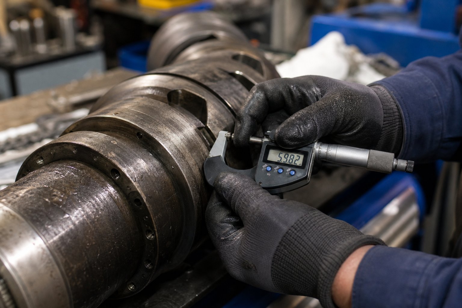
A twin-screw extruder machine can hold tight tolerances and deliver consistent output for thousands of hours—until it cannot. Wear does not announce itself with a dramatic failure. It creeps in gradually: a fraction of a millimeter lost from a screw flight here, a slight bore enlargement there. By the time output drops noticeably or melt temperature climbs without explanation, the damage has already been costing you money for weeks or months. Knowing what to look for—and when to act—separates proactive maintenance programs from expensive reactive ones.
Wear Patterns and Warning Signs in Screws and Barrels
Three primary wear mechanisms attack extruder screws and barrels, and each one leaves a different signature on the hardware:
- Abrasive wear — The most common culprit in compounding operations, driven by hard filler particles like glass fiber, calcium carbonate, and silica grinding against screw flights and barrel walls. Abrasive wear concentrates in zones where solids fraction is highest—the feed and melting sections—and accelerates dramatically above 30–40% filler loading.
- Adhesive wear — Metal-to-metal contact between screw flight tips and barrel bore under high side forces. This occurs when solids block the channel momentarily—often at the end of the melting zone or at the entry to a mixer—creating lateral forces that press the screw against the barrel wall. As Plastics Technology details, poor barrel alignment and faulty screw design are the root causes behind this type of contact wear.
- Corrosive wear — Chemically aggressive polymers such as fluoroplastics, PVC (which releases HCl at processing temperatures), and certain flame-retardant packages attack barrel and screw surfaces at the molecular level, pitting and eroding metal independently of mechanical stress.
Different processing materials accelerate different mechanisms. A glass-fiber-reinforced nylon compound punishes hardware through abrasion, while a halogenated flame-retardant masterbatch combines corrosion with moderate abrasion. Understanding which mechanism dominates your application lets you select appropriate metallurgy and set realistic inspection intervals.
So how do you know wear has progressed beyond acceptable limits? Watch for these indicators during routine production monitoring:
- Increasing specific energy consumption — More kWh per kilogram of throughput at constant screw speed signals that the screws are doing less useful work per revolution, forcing the motor to compensate.
- Declining output at constant screw speed — As flight clearance widens, material leaks backward over the flight tips instead of being conveyed forward. Throughput falls, and operators instinctively raise screw speed to compensate—masking the root problem.
- Rising melt temperature at constant conditions — Increased leakage flow over worn flight tips generates frictional heat without productive mixing, pushing discharge temperature upward. For a 100 mm diameter screw processing 1 MI polyethylene, research shows that doubling the flight clearance from new can raise discharge temperature by 10 °C or more at constant output rate.
- Visible scoring or galling on screw flights — Grooves, discoloration, or rough patches on flight surfaces confirm adhesive or abrasive contact that has progressed past the hard-facing layer.
- Increasing gap between screw flight and barrel wall — Measurable with bore gauges during scheduled shutdowns. A gap exceeding two to three times the original clearance warrants serious evaluation; four times the original clearance is a common replacement threshold for general-purpose applications.
Preventive Maintenance and Replacement Planning
Catching wear early depends on establishing consistent inspection routines. For twin screw extruder machine operations running abrasive compounds, quarterly bore measurements of barrel inside diameter and screw flight outside diameter should be standard practice. Less demanding applications may tolerate semi-annual checks. In either case, record measurements in a log that tracks wear progression over time—a bore diameter trending upward by 0.02 mm per quarter tells you far more than a single snapshot measurement.
When measurements show clearances approaching the replacement threshold, you face a decision: refurbish or replace?
- Refurbishment — Re-welding hard facing onto worn screw flights can restore clearances at a fraction of new-part cost. However, each refurbishment cycle degrades the base metal, and the bond between new hard facing and previously heat-affected substrate weakens progressively. Industry experience suggests limiting refurbishment to no more than three cycles per screw element before replacement becomes necessary.
- Replacement — When bore wear exceeds liner thickness limits, or when screw elements have been refurbished multiple times, new components are the only reliable path. Iron-based bimetallic barrel liners typically outlast screws by a factor of roughly three, so planning screw replacements in conjunction with periodic barrel bore checks helps synchronize the maintenance cycle.
Timely replacement prevents a cascade of secondary problems—degraded product quality, increased reject rates, unplanned line shutdowns—that cost far more than the replacement hardware itself. Keeping a spare set of screw elements on hand eliminates extended downtime during changeovers. For barrel replacement, sourcing from a supplier with expertise in your specific processing application ensures the metallurgy and dimensional tolerances match your requirements. Operations running parallel twin screw extruders in compounding, masterbatch, recycling, or pelletizing applications can evaluate NANHAIYA's parallel twin screw barrel offerings, which are engineered as custom and standard replacement barrels for these high-wear processing environments.
Troubleshooting Common Processing Problems
Even with disciplined maintenance, processing problems arise. The challenge is diagnosing whether the root cause is wear-related, configuration-related, or driven by upstream variables like feedstock quality. The troubleshooting reference below organizes the most common symptoms with their likely causes and corrective actions—designed as a quick-reference tool you can consult directly on the production floor.
| Symptom | Likely Causes | Corrective Actions |
|---|---|---|
| Poor filler dispersion | Worn kneading blocks with reduced shear capability; insufficient kneading zone length; filler agglomerates bypassing mixing zones due to excessive clearance; incorrect stagger angle selection | Inspect and replace worn kneading elements; extend kneading zone or increase stagger angle to 60°–90°; verify side-feeder positioning ensures filler enters a fully molten zone; check filler moisture content |
| Material degradation or discoloration | Excessive residence time from over-aggressive reverse elements; barrel temperature setpoints too high; stagnant material in dead zones caused by worn self-wiping surfaces; failed barrel heater creating localized hot spots | Shorten reverse element length or replace 90° kneading blocks with forward-staggered alternatives; reduce barrel temperature in affected zones; replace worn screw elements to restore self-wiping; inspect and replace faulty heater bands |
| Inconsistent output rate (surging) | Worn conveying elements in the feed zone reducing intake capacity; feeder calibration drift; bridging in the feed hopper; inconsistent bulk density of incoming material | Replace worn feed-zone conveying elements; recalibrate gravimetric feeders; install hopper agitation or vibration; verify raw material lot-to-lot consistency |
| High torque or motor overload | Barrel temperature too low for adequate melting; excessive fill level from feeder overshoot; unmelted pellets jamming kneading zones; screw elements installed in wrong sequence after maintenance | Raise barrel temperatures in melting zones; reduce feed rate and re-establish stable starve-fed operation; verify screw element sequence matches the documented configuration; check for foreign material contamination in feedstock |
| Vent flow or vent flooding | Worn reverse elements upstream of vent port failing to maintain melt seal; excessive throughput rate filling vent zone above critical level; inadequate vacuum pressure; barrel temperature too low creating unmelted polymer in vent area | Replace worn reverse elements to restore melt seal integrity; reduce throughput to lower fill level in vent zone; verify vacuum pump capacity and check for blockages in vacuum line; raise barrel temperature upstream of vent to ensure complete melting before the vent port |
One diagnostic principle cuts across all five symptoms: determine first whether the problem is chronic or transient. If it appears every time you run a specific formulation, the root cause almost certainly lies in the screw configuration or fundamental process parameters. If a historically stable formulation suddenly goes off-spec, investigate what changed—a new raw material lot, a recently reassembled screw, a failed heater band, or even seasonal humidity shifts affecting hygroscopic resins. As HAISI's troubleshooting framework emphasizes, chronic problems demand process redesign while transient issues require detective work through the five key variables: screw condition, screw speed, feed rate, temperature, and environment.
The economics of maintenance planning deserve the same engineering rigor as the process itself. Every hour a twin screw extruder machine runs with degraded clearances, it produces compound that may technically meet specification but sits at the edge of the quality window—and edges are where customer complaints originate. Factoring the cost of a replacement barrel or screw set against the cumulative cost of reduced throughput, elevated energy consumption, and quality risk almost always favors proactive replacement. For processors evaluating twin screw extruder manufacturers for replacement parts, the deciding factors should be metallurgical expertise matched to your wear mechanism, dimensional accuracy to OEM tolerances, and lead time that aligns with your maintenance schedule—not just twin screw extruder price alone.
Frequently Asked Questions About Twin Screw Extruders
1. What is the difference between co-rotating and counter-rotating twin screw extruders?
Co-rotating twin screw extruders have both screws turning in the same direction, producing a self-wiping figure-eight flow pattern that delivers high shear and excellent dispersive mixing. They run at speeds up to 1,200 rpm and excel at compounding, masterbatch, and reactive extrusion. Counter-rotating extruders turn the screws in opposite directions, forming closed C-shaped chambers that act as positive displacement pumps. They operate at lower speeds (10-60 rpm), generate less shear heat, and are preferred for thermally sensitive materials like rigid PVC pipe and profile extrusion. Your choice should be driven by whether your process demands aggressive mixing flexibility or gentle, pressure-stable conveying.
2. Why choose a twin screw extruder over a single screw extruder?
Twin screw extruders operate in starve-fed mode, decoupling throughput from screw speed so you can independently adjust shear input and feed rate. The intermeshing screw geometry forces material to transfer repeatedly between channels, achieving thorough dispersive and distributive mixing in a single pass. Single screw extruders are flood-fed, coupling output to screw speed, and rely on barrel-wall friction with limited cross-channel mixing. However, single screw machines remain the better choice for simple melting and pumping of pre-compounded pellets, film extrusion, and applications where capital cost matters more than mixing intensity.
3. How do screw elements affect twin screw extruder performance?
Modular screw elements are the primary tuning tool on a twin screw extruder. Forward-pitch conveying elements control material transport speed and fill level. Kneading blocks with stagger angles of 30-90 degrees deliver dispersive or distributive mixing depending on disc width and offset angle. Toothed and gear-type mixing elements provide gentle blending without excessive shear. Reverse elements create melt seals upstream of vent ports and build pressure barriers. The sequence of these elements along the shaft determines the complete processing profile, and rearranging them changes outcomes without purchasing new hardware. The guiding principle is that screw design should always follow the process requirements of your specific polymer and additive package.
4. What maintenance indicators signal that twin screw extruder barrels or screws need replacement?
Key warning signs include rising specific energy consumption at constant screw speed, declining throughput without changes to feed rate, increasing melt temperature under stable operating conditions, and visible scoring or galling on screw flight surfaces. Measuring the gap between screw flight tips and barrel bore during scheduled shutdowns is the most reliable diagnostic. When clearances reach two to three times the original specification, evaluate replacement options. Beyond four times the original clearance, replacement is typically mandatory. Quarterly bore measurements for abrasive compound operations and semi-annual checks for less demanding applications help you track wear progression and plan replacements before quality begins to suffer.
5. How do you scale up a twin screw extrusion process from lab to production?
Successful scale-up hinges on matching specific mechanical energy (SME) and specific thermal energy between laboratory and production extruders rather than simply increasing machine size. Preserve geometric similarity by maintaining proportional L/D ratios and OD/ID ratios across scales. Throughput scaling follows either the cube of the diameter ratio (power-limited processes) or the square (heat-transfer-limited processes). Record SME, melt temperature, residence time, and torque response meticulously at lab scale, then use those values as benchmarks when optimizing production parameters. Common pitfalls include underestimating the reduced surface-area-to-volume ratio at larger diameters, which limits heat removal capacity, and residence time shifts that can push sensitive polymers toward degradation.
Written by
Nanhaiya Technical Team
Zhoushan Nanhaiya Plastic Machinery Co., Ltd.
The Nanhaiya technical team supports screw and barrel manufacturing projects through application review, technical communication, custom manufacturing coordination, and production and quality control.
Discuss Your Application
Related Articles
More insights on screw barrel technology and plastics processing.

What Nobody Tells You About Screw Barrel For Plastic Machine Design
Oct 10, 2026
Learn how screw barrel for plastic machine design affects melt quality, throughput, and wear life. Covers geometry, resin matching, troubleshooting, and sourcing.
Read Article
Single Screw Extruder for Sheet: Stop Guessing, Start Specifying
Oct 9, 2026
Learn how to specify a single screw extruder for sheet production. Covers screw geometry, resin-specific processing, troubleshooting, and maintenance best practices.
Read Article
PE Pipe Extruder Machine: What Datasheets Won't Tell You
Oct 9, 2026
Learn how a PE pipe extruder machine works, key specs explained, material grade selection, maintenance tips, and buyer guidance beyond the datasheet.
Read ArticleLooking for something else?
Search by material, symptom or product and jump straight to the relevant page.
These are navigation suggestions based on keyword matching — not a quotation, not a delivery commitment, and not a substitute for engineering review. Final specification is confirmed by our engineers against your drawings and processed material.
Need help with screw barrel selection?
Share your machine model, processed material and application. Our team can help with pricing and technical support.