

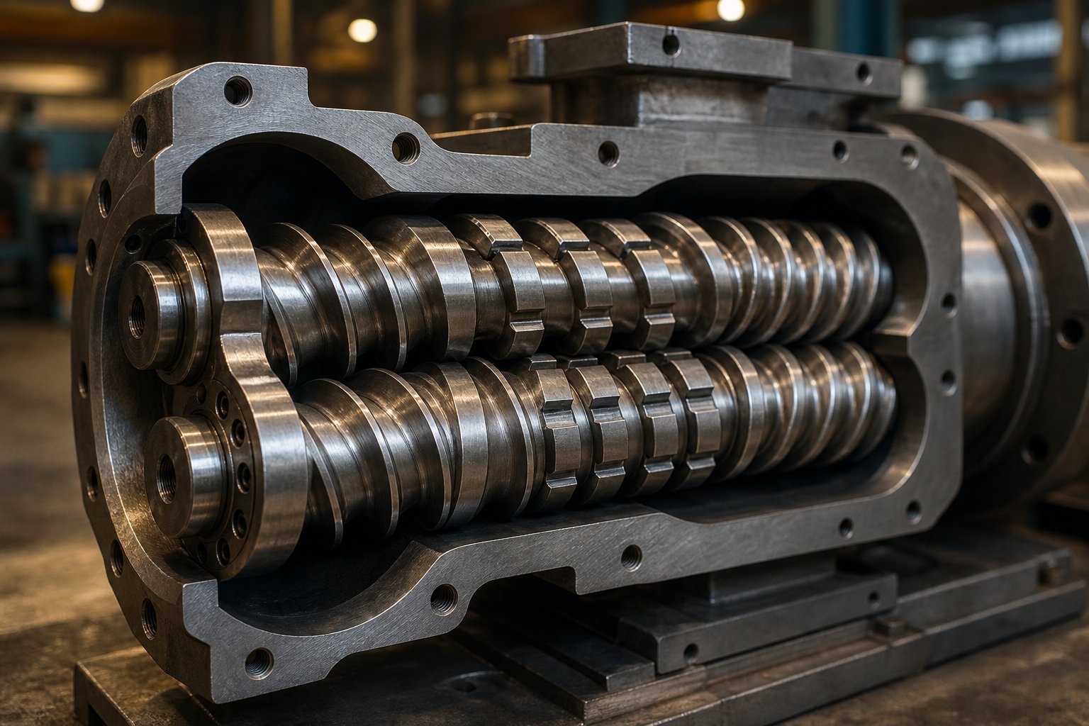
What a Twin Screw Extruder Is and Why Its Working Principle Matters
Imagine two helical screws, side by side, rotating inside a heated barrel. As they turn, their flights intermesh like precisely engineered gears—grabbing raw material, dragging it forward, compressing it, melting it, and mixing it into a uniform melt. That, at its simplest, is the twin screw extruder working principle. But the simplicity ends there.
What Is a Twin Screw Extruder
A twin screw extruder is a machine built around two co-rotating or counter-rotating screws housed within a figure-eight-shaped barrel. Its job is to convey, melt, mix, and shape polymers, food ingredients, pharmaceuticals, and other processable materials. Unlike a single screw extruder—which relies on one rotating screw and depends heavily on friction between the material and the barrel wall—a twin-screw extruder uses the intermeshing geometry of its two screws to actively push, shear, and recirculate material through the processing length.
The twin screw extruder working principle is based on two intermeshing screws rotating inside a heated barrel, where material is conveyed by positive displacement and screw-drag mechanics, melted through combined shear and thermal energy, and intensively mixed via the continuous material exchange between the two screws—producing a homogeneous melt that is shaped through a die.
This distinction from single screw designs is not just a matter of doubling hardware. When people explore extruders meaning and function, they often assume a double screw extruder simply doubles the conveying capacity. In reality, the intermeshing zone between twin screws creates flow patterns, shear fields, and self-cleaning behaviors that have no equivalent in single screw extrusion. The machine operates on fundamentally different transport and mixing principles.
Why the Working Principle Matters for Process Success
Here is where most resources fall short: they describe what a twin screw extruder does without explaining how the underlying mechanics determine product quality. Understanding the working principle—how drag flow and pressure flow interact, how kneading elements generate shear, how screw configuration controls residence time—gives engineers and process technicians the tools to troubleshoot problems at their root rather than chasing symptoms.
For technical buyers evaluating equipment, grasping how twin screw extrusion actually works separates informed purchasing decisions from guesswork. You'll be able to match screw geometry to your material, predict how process changes affect output, and communicate more effectively with equipment suppliers.
This article is structured to build that understanding layer by layer—starting with the core flow mechanics most resources gloss over, then moving through modular screw and barrel design, process parameter control, energy balance, and real-world applications. Each layer connects directly to the physics happening inside those two intermeshing screws.
Core Mechanics of Material Transport and Mixing in Twin Screws
Every pellet that enters a twin screw extruder is caught between two competing forces. One drags it toward the die. The other pushes it back. The balance between these forces—and the screw geometry that controls them—determines how material moves, melts, and mixes along the entire processing length.
Drag Flow and Pressure Flow Explained
When the extruder screw rotates, it drags material forward through friction against the barrel wall. This is drag flow—the primary conveying mechanism in screw extrusion. Picture the screw flight acting like a moving wall that sweeps material downstream, much like an Archimedes pump. The velocity profile across the channel depth is roughly linear: fastest near the barrel surface, zero at the screw root.
Pressure flow works in the opposite direction. Whenever material encounters a restriction—a kneading block, a reverse element, or the die itself—pressure builds up. That pressure gradient drives material backward through the screw channel. The resulting velocity profile is parabolic, peaking at the channel center and dropping to zero at both walls.
The net throughput at any point along the extruder is the difference between these two flows. Screw geometry gives engineers direct control over each component: increasing channel depth boosts drag flow capacity, while tighter restrictions or higher die pressure amplify the backward pressure flow. Analytical models dating back to the 1950s describe this relationship mathematically, and the core physics still underpins how every modern extruder twin screw system is designed.
| Characteristic | Drag Flow | Pressure Flow |
|---|---|---|
| Direction | Forward (toward the die) | Backward (toward the feed) |
| Driving Force | Screw rotation against barrel wall | Pressure gradient from downstream restrictions |
| Velocity Profile | Approximately linear across channel depth | Parabolic across channel depth |
| Primary Controls | Screw speed (RPM), channel depth, helix angle | Die resistance, reverse elements, kneading block configuration |
| Dependence on Viscosity | Independent for Newtonian fluids | Directly dependent on melt viscosity |
The Self-Wiping Mechanism and Intermeshing Geometry
What truly separates twin screws from single screw designs is the intermeshing zone. In closely intermeshing co-rotating screw extruders, the flight of one screw fits tightly into the channel of the other. As both screws rotate, each flight continuously scrapes material off its partner's surface—a phenomenon known as self-wiping.
Why does this matter so much? Imagine material sticking to a hot metal surface for minutes instead of seconds. Thermal degradation, discoloration, and crosslinking become inevitable. Self-wiping eliminates these dead zones. Every surface is continuously cleaned, so no polymer remains in contact with the barrel or screw long enough to degrade. Research on intermeshing configurations confirms that this close distance between screws enables them to clean each other's surfaces of residue and stagnant layers, dramatically improving both product quality and process consistency.
The tight clearances also force material through a high-shear gap as it transfers from one screw to the other. This repeated material exchange—passing back and forth in a figure-eight pattern—creates intensive mixing that simply cannot occur in a single-channel design. It is the geometric foundation for the mixing performance that makes twin screw extrusion the industry standard for compounding.
Distributive vs Dispersive Mixing
Not all mixing is the same, and confusing the two types is one of the most common mistakes in screw design. Industry practitioners emphasize that understanding the distinction between distributive and dispersive mixing is essential for selecting the right screw elements.
Dispersive mixing breaks things apart. When cohesive materials like carbon black agglomerates or pigment clusters enter the melt, they must be subjected to shear stresses that exceed their cohesive strength. Wide kneading discs on the extruder screw generate this high shear—the disc plows through the polymer, creating intense stress fields that fracture agglomerates down to their primary particle size.
Distributive mixing spreads things around. Once particles are broken down—or when free-flowing additives simply need to be incorporated uniformly—the goal shifts to spatial homogeneity. Narrow kneading discs achieve this through a scissoring action: slicing through the melt, dividing it, and recombining it repeatedly until every component is evenly distributed throughout the polymer matrix.
Both types are essential for quality compounding. A material can be well-dispersed but poorly distributed—particles broken to their ultimate size but concentrated in one region of the melt. Conversely, large agglomerates can be spread evenly throughout the polymer without ever being broken down, creating a uniform but functionally defective compound. The stagger angle of kneading block discs plays a critical role here: shallow angles (around 30 degrees) promote forward conveying with gentle distributive mixing, while steeper angles (60 to 90 degrees) restrict flow and intensify dispersive shear. Designing the right combination for your specific formulation is where the science of the twin screw extruder working principle meets the art of screw configuration.
Yet kneading blocks and mixing elements are only part of the story. The real versatility of modern screw extruders lies in their modular design—the ability to arrange dozens of individual elements along a single shaft, each performing a distinct function in the processing sequence.
Co-Rotating vs Counter-Rotating Twin Screw Configurations Compared
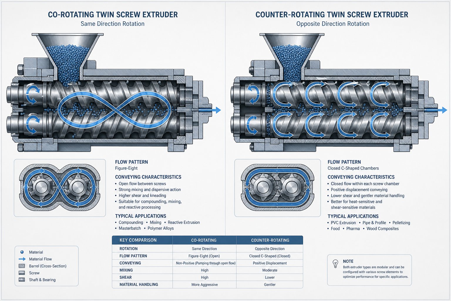
Modularity gives twin screw extruders their flexibility, but the direction each screw rotates determines something far more fundamental—how material actually flows through the machine. Two screws can turn the same way or in opposite directions, and that single design choice reshapes the flow path, shear intensity, and pressure-building behavior so dramatically that the two configurations serve almost entirely different markets. Understanding co rotating and counter rotating twin screw extruder mechanics is what separates a confident equipment decision from an expensive mismatch.
Co-Rotating Twin Screw Extruder Flow Mechanics
In a co rotating twin screw extruder, both screws turn in the same direction—both clockwise or both counterclockwise. When material reaches the intermeshing zone, it cannot simply stay on one screw. The matching rotation forces it off one flight and onto the other, creating a continuous figure-eight flow path as the melt transfers back and forth between the two screws along the barrel length.
This figure-eight pattern is critical. Every time material crosses from one screw to the other, it passes through a high-shear gap where the flights nearly touch. The result is intensive and repeated mixing—each cross-over event splits, reorients, and recombines the melt. As extrusion specialists at Technovel explain, intense shear fields develop both between the screws and between the screws and the barrel, while kneading elements add an elongational flow component that imposes a complex deformation history on the material.
The co-rotating configuration also delivers the strongest self-wiping behavior. Because the flights of one screw trace the channel profile of the other, tight clearances ensure continuous surface cleaning. Dead zones are virtually eliminated, keeping residence time distribution narrow and minimizing thermal degradation risk.
These characteristics explain why the co-rotating design dominates compounding applications. Superior distributive and dispersive mixing, excellent self-wiping, and the ability to operate at high screw speeds—often 300 to 1,200 RPM—make it the standard for engineering plastics, masterbatch, polymer blends, nanocomposites, and reactive extrusion.
Counter-Rotating Twin Screw Extruder Flow Mechanics
Flip one screw's rotation direction and the flow physics change entirely. In a counter-rotating configuration, the screws rotate in opposite directions, and material at the intermeshing zone gets drawn inward rather than handed across. This geometry creates closed, approximately C-shaped chambers between the screw flights—each chamber trapping a discrete volume of material and pushing it forward like a gear pump.
This positive displacement conveying mechanism is the defining advantage. Material transport depends strongly on screw rotation itself rather than on friction or viscosity, delivering stable metering with low melt pressure fluctuation. Because the C-shaped chambers are nearly sealed, backflow is minimal and output is predictable—even with slippery powders or materials with erratic flow behavior.
Shear stress in the counter-rotating design is inherently lower. The screws move in opposite directions at the intermeshing point, so relative velocities are lower than in the co-rotating case. A calendering effect appears instead—material undergoes compressive and elongational deformation as it passes between the screws, achieving moderate dispersion under gentle conditions. This keeps frictional heat low, which is exactly what thermally sensitive materials like rigid PVC require to avoid decomposition.
Counter-rotating designs come in two distinct geometries. A parallel twin screw extruder features two screws of equal diameter running side by side along the full barrel length—common in PVC pipe and sheet production. A conical twin screw extruder tapers both screws from a larger feed-end diameter down to a smaller discharge diameter, generating high pressure in a compact footprint. Conical designs are widely used for PVC profile extrusion, where pressure stability and gentle processing are paramount.
| Factor | Co-Rotating | Counter-Rotating |
|---|---|---|
| Flow Pattern | Figure-eight; material transfers between screws | Closed C-shaped chambers; positive displacement |
| Shear Level | High; intense shear at intermeshing zone | Low to moderate; calendering effect dominates |
| Self-Wiping Ability | Excellent; continuous surface cleaning | Limited; some stagnation in chamber corners |
| Mixing Intensity | High distributive and dispersive mixing | Moderate; better suited to gentle dispersion |
| Typical Speed Range | 300–1,200 RPM | 5–80 RPM (parallel); 5–40 RPM (conical) |
| Pressure Generation | Moderate; some fluctuation | High and stable; gear-pump-like behavior |
| Typical Applications | Compounding, masterbatch, reactive extrusion, recycling | PVC pipe, profile, and sheet extrusion; heat-sensitive materials |
So how do you choose? The decision is not about which configuration is "better"—it is about matching flow mechanics to process requirements. When the goal is intensive mixing, rapid homogenization, and flexible screw design for diverse formulations, the co-rotating layout is the clear fit. When the process demands stable pressure buildup, low shear, and gentle material handling—especially for thermally sensitive polymers like PVC—the counter-rotating design delivers what co-rotating machines cannot.
Whichever configuration you select, though, the real processing power comes from the individual screw elements mounted along the shaft. How kneading blocks, conveying elements, and reverse-pitch segments are sequenced along the barrel determines whether a given configuration reaches its full potential—or falls short.
Modular Screw Elements and Configuration Design
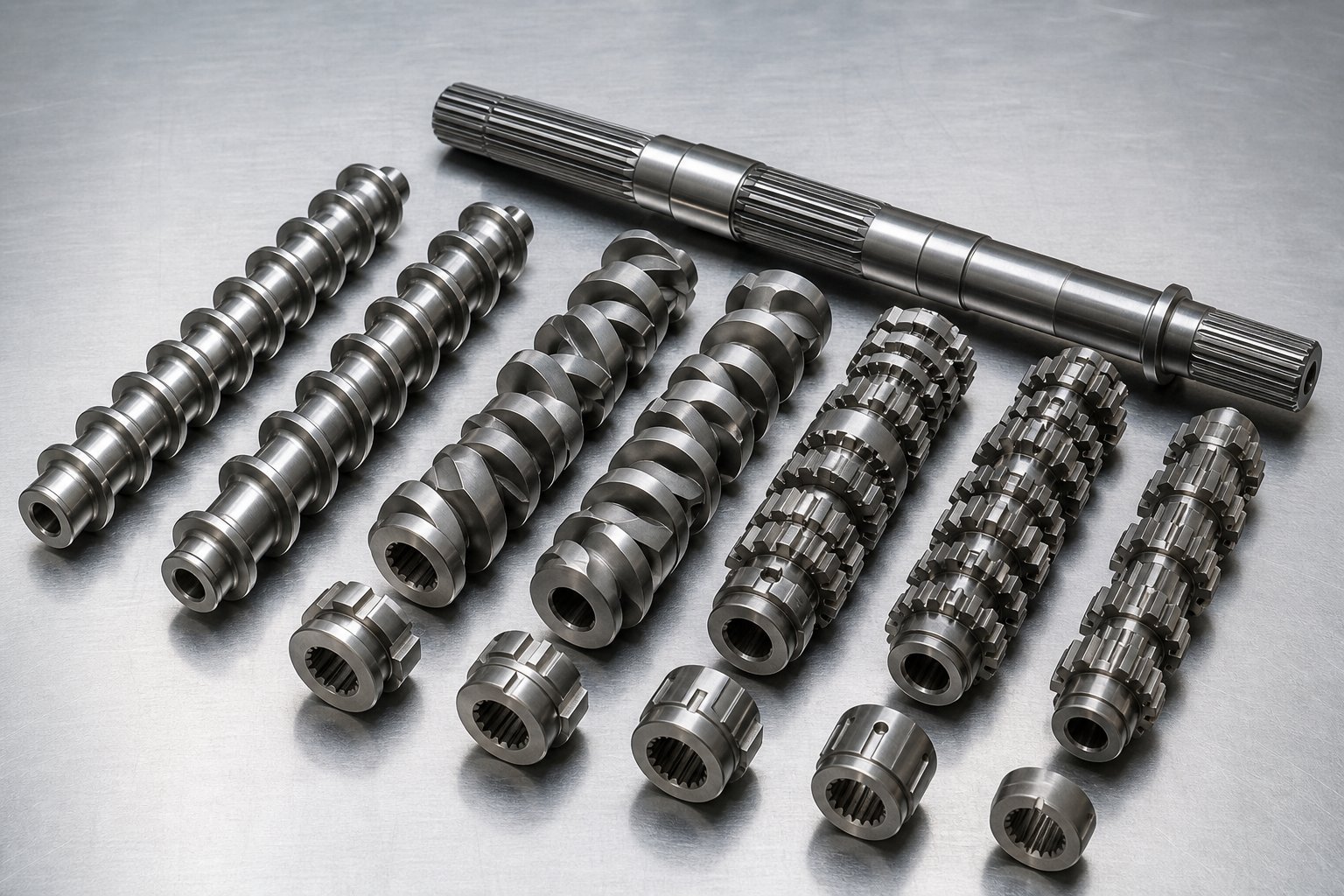
A twin screw extruder's barrel may look like a single piece of hardware from the outside, but the real engineering happens on the shaft inside. Every modern co-rotating extruder system uses a segmented screw design—individual elements slid onto a splined shaft and locked in sequence. Swap a few elements, and the same machine behaves like an entirely different processor. This modular architecture is the reason a single extruder can compound glass-filled nylon one week and process color masterbatch the next.
The question is: what does each element actually do, and how do you arrange them into a configuration that works?
Conveying Elements and Their Geometry
Conveying elements are the workhorses—helical flights that look like traditional screws. Their primary job is moving material forward, but the pitch (also called lead length) determines how aggressively they do it.
A large-pitch element covers more axial distance per revolution. It grabs material quickly and transports it downstream with minimal compression, which keeps fill levels low and residence time short. You'll typically find these coarse-pitch elements in the feed zone, where bulk pellets or powder need to be pulled in rapidly without jamming.
Reduce the pitch, and the element conveys less volume per revolution. Material spends more time in each channel, fill levels rise, and local pressure builds. Tighter pitch near the die is standard practice for stable metering and consistent pressure delivery. The pitch gradient along the screw essentially creates a controlled compression profile from feed to discharge.
Then there are reverse-pitch elements—conveying elements with the opposite helix direction. These actively push material backward against the main flow, generating a pressure dam upstream. Why would you want that? Because reverse elements create melt seals. A melt seal is a fully filled, high-pressure zone that isolates one processing section from another—essential for separating a venting zone from an upstream mixing zone so that volatile gases escape through the vent port instead of traveling back toward the feed throat.
Kneading Blocks and Mixing Elements
If conveying elements are the workhorses, kneading blocks are the precision tools. A kneading block consists of multiple elliptical discs stacked on the shaft, each offset from its neighbor by a specific stagger angle. That angle is the single most important variable controlling mixing behavior.
At a 30-degree stagger angle, each disc is only slightly offset. The block still conveys material forward while gently splitting and recombining the melt—primarily distributive mixing. At 60 degrees, forward conveying drops significantly and shear intensity rises. The melt spends more time being worked between the disc tips and the barrel wall, making this a good balance point for moderate dispersive action. At 90 degrees, the block becomes neutral—it has zero net conveying capacity. Material oscillates back and forth across the discs, experiencing intense shear and pressure fluctuations that excel at breaking agglomerates and driving dispersive mixing.
Disc width matters too. As detailed in analyses of kneading block geometry, narrower discs create more frequent flow disruptions along the screw axis, generating higher local pressure fluctuations and stronger dispersive action. Wider discs produce smoother flow paths—gentler on heat-sensitive materials and better for distributive blending.
Beyond kneading blocks, specialized mixing elements like gear-type (ZME) and turbine mixing elements (TME) achieve distributive mixing through a different approach entirely. These elements repeatedly divide and recombine melt streams through grooves, slots, or offset channels without imposing the high shear stress associated with kneading discs. They are invaluable in a plastic extruder screw configuration when you need uniform spatial distribution of already-fine additives—or when processing fiber-reinforced compounds where excessive shear would break fibers and destroy mechanical properties.
Designing a Screw Configuration for a Specific Process
Knowing what each element does individually is useful. Knowing how to sequence them along the shaft is what separates a functional process from a great one. The logic follows the material's transformation: each zone on the screw addresses a specific stage of processing, and the elements within that zone are selected to match.
Here is a typical element sequence from feed to discharge in a compounding plastic extrusion screw configuration:
- Feed zone (large-pitch conveying elements): Pull raw pellets or powder from the hopper into the barrel. Coarse pitch keeps the zone starve-fed, preventing torque spikes and bridging.
- Transition/melting zone (decreasing-pitch conveying elements + forward kneading blocks): Compress material against the heated barrel. Early kneading blocks initiate melting through viscous shear, working in concert with conducted barrel heat.
- First mixing zone (intensive kneading blocks at 60–90 degrees): Fully molten polymer passes through high-shear kneading to disperse pigments, break agglomerates, or blend incompatible phases. This is where the heaviest dispersive and distributive work occurs.
- Melt seal (reverse-pitch element or reverse kneading block): Creates a fully filled pressure dam that isolates the upstream mixing zone from the downstream vent, preventing melt from flowing backward into the vent port.
- Vent zone (large-pitch conveying elements under an open barrel port): Low fill and low pressure allow moisture, volatiles, or trapped air to escape through the vent opening.
- Second mixing zone (moderate kneading or distributive elements), if needed: Additional blending for downstream-fed fillers or final homogenization. Gear-type elements or mild kneading blocks are common here.
- Metering zone (tight-pitch conveying elements): Build stable, consistent pressure to push the homogeneous melt through the die at a uniform rate.
This sequence is not arbitrary—it mirrors the physics of material transformation, and each element choice is driven by what the material needs at that specific point. Engineers designing a screw plastic extruder configuration for a new formulation typically start with this framework, then adjust element types, lengths, and positions based on trial runs and process data.
One more variable ties this entire design together: L/D ratio—the ratio of screw length to screw diameter. Practical compounding applications typically use L/D values between 40 and 60, which provide enough barrel length to accommodate feeding, melting, multiple mixing zones, devolatilization, and metering in a well-spaced sequence. Reactive extrusion or processes requiring extended residence time may push L/D to 100 or beyond. Shorter L/D ratios compress these zones together, limiting flexibility—there is simply less room on the shaft to arrange the elements each processing stage demands.
The takeaway? A screw plastic extruder configuration is not a fixed recipe. It is a designed sequence where every element—pitch, stagger angle, disc width, element length—is selected to control what happens to material at that exact location in the barrel. The modular design means you can iterate, swap elements, and refine the configuration without replacing the entire screw. That adaptability is what makes the twin screw extruder working principle so powerful in practice.
Yet the screws are only half of the modular equation. The barrel segments surrounding them—closed processing sections, open feed ports, and vented sections—play equally critical roles in determining what the extruder system can actually accomplish at each processing stage.
Modular Twin Screw Barrel Sections and Devolatilization
Screws get all the attention, but the barrel surrounding them is just as modular—and just as critical. A twin screw barrel is not a single tube. It is an assembly of individual barrel sections, each independently heated and cooled, bolted together in a sequence that mirrors the process requirements. Most manufacturers offer configurations of ten, eleven, or twelve individual sections, and every one of those positions can be tailored to serve a specific function along the processing length.
Sounds like a lot of flexibility? It is. The twin screw and barrel system together form a fully configurable platform—and understanding which barrel type goes where is essential for building processes that actually work.
Types of Barrel Sections and Their Roles
Each barrel section features the characteristic figure-eight bore through which the two screws rotate. What differs is whether the section is sealed, open to the atmosphere, or ported for auxiliary equipment. Here are the main types you will encounter:
- Closed barrel sections: The most common type. These sections fully encase the polymer melt on all sides except the figure-eight screw bore. All surfaces are temperature-controlled through integrated heating and cooling channels, making them the standard for solid conveying, melting, and mixing zones. You will find closed barrels wherever the process requires contained, temperature-regulated material handling.
- Open-top (feed) barrel sections: These feature an external opening at the top of the barrel through which raw materials enter. The primary feed barrel is almost always positioned at the first section of the extruder. For low-bulk-density powders that entrap air during feeding, a second open barrel can be placed upstream as a rear-venting arrangement—allowing displaced air to escape without obstructing the powder's path into the screws.
- Combination (side-feeder) barrel sections: These include both a side opening for a twin-screw side stuffer and often a small upstream vent port for displaced air. They are positioned downstream—typically at the fourth or fifth section—where fillers, fibers, or additives are introduced into already-molten polymer.
- Vented barrel sections: Open-top sections dedicated to removing volatiles. They connect to either atmospheric vents or vacuum systems and are placed near the end of the extruder, usually in the second or third section upstream of the die to allow volatile removal before the melt reaches discharge.
- Liquid injection barrel sections: Specialized closed barrels fitted with an injection port and needle valve, used for metering liquid additives, oils, or reactive agents directly into the melt stream via a plunger pump.
A typical barrel assembly follows a logical progression: an open feed barrel first, followed by several closed barrels for melting and mixing, a combination barrel for downstream additive feeding, more closed barrels for further mixing, a vented barrel near the end for devolatilization, and a final closed barrel before the die.
Devolatilization and Venting Principles
Why does venting matter? Because trapped moisture, residual monomers, dissolved gases, and solvents will degrade product quality if they remain in the melt. Bubbling, poor surface finish, reduced bulk density in pellets, and compromised mechanical properties are all consequences of inadequate volatile removal.
The extruder screw and barrel work together to make devolatilization possible. Here is how. Upstream of the vent port, restrictive screw elements—typically reverse-pitch conveying or 90-degree kneading blocks—create a melt seal. This fully filled, high-pressure zone prevents vacuum from pulling backward through the extruder and isolates the vent from upstream processing zones. Immediately downstream of that seal, large-pitch conveying elements create a partially filled, low-pressure zone directly beneath the vent opening. This low fill level exposes maximum polymer surface area to the vent environment, allowing volatiles to flash off and escape.
Two venting modes are available. Atmospheric venting simply opens the barrel to ambient pressure—sufficient for removing entrained air or moderate moisture levels. Vacuum venting connects the vent port to a vacuum pump, dropping the partial pressure of volatiles far below atmospheric. As devolatilization experts note, each vacuum vent can reduce volatile concentration by roughly an order of magnitude, so a triple-vented machine can bring a 50%-solids feed stream down to below 0.1% residuals. For stringent food-contact, medical, or high-performance specifications, vacuum venting is essential.
One practical caution: if die pressure rises too high or screw speed changes destabilize the downstream melt seal, molten polymer can back up into the vent port—blocking the vacuum line and disrupting production. Proper seal design and vent placement are critical to stable operation.
Downstream Feeding and Side Stuffers
Not every ingredient should enter the extruder at the main feed throat. Fibers, mineral fillers, and heat-sensitive additives fare poorly when forced through the high-shear melting zone alongside the base polymer. Glass fibers, for example, would be ground to a powder by the intense shear forces generated during the solid-to-melt phase transition—destroying the very aspect ratio that gives them their reinforcing value.
Side stuffers solve this problem. A side feeder consists of a hopper and a pair of small conveying screws that push solid materials through the combination barrel directly into the already-molten polymer stream. Because the polymer is fully melted before the additive arrives, the shear environment is far gentler. Narrow-disc kneading blocks downstream of the side feeder then incorporate the fibers or fillers with minimal attrition.
Low-melting additives—waxes, fatty acid slip agents, and similar lubricants—also benefit from downstream feeding. Their low viscosity and lubricating nature can interfere with polymer melting if introduced at the feed throat, causing the resin to slip through the melting zone without fully converting. Feeding them downstream into an established melt avoids this entirely.
Together, the modular barrel and the modular screw create a system where every inch of the extruder's processing length can be purpose-built. Yet all of this configurability only reaches its potential when the operator understands how material is fed into the machine in the first place—and how feed strategy interacts with screw speed, throughput, and the process parameters that ultimately determine product quality.
Starve Feeding and Process Parameter Control in Twin Screw Extruders
Here is a misconception that trips up even experienced processors: if you increase screw speed, you increase output. On a single screw extruder, that is largely true. On a co-rotating twin screw extruder, it is not—and the reason cuts to the heart of how twin-screw extruders actually operate. The feeding strategy changes everything.
Starve Feeding vs Flood Feeding
A conventional single screw extruder runs flood-fed. The hopper is full, gravity pushes pellets into the screw channel, and output is directly tied to screw RPM. Turn the screw faster, you push more material through the die. The screw channel stays fully filled from the feed throat through to the metering zone, and the operator has one primary lever—screw speed—to control both throughput and mixing.
Twin screw extruders flip that relationship. In the twin screw extrusion process, a loss-in-weight or volumetric feeder meters material into the barrel at a precisely controlled rate that is deliberately set below the screw's maximum conveying capacity. The result? Partially filled screw channels in the conveying zones, with fully filled regions appearing only where restrictive elements—kneading blocks, reverse-pitch elements, or the die itself—create backpressure.
This is starve feeding, and its practical impact is enormous. Because the feeder—not the screw—determines throughput, screw RPM can be adjusted independently without changing output rate. Imagine you need more intensive mixing for a difficult pigment dispersion. In a flood-fed system, increasing screw speed would simultaneously raise throughput, reducing residence time and potentially undermining the very mixing improvement you wanted. In a starve-fed twin screw extruder, you simply increase RPM while holding the feeder rate constant. The screws turn faster, fill level drops, specific energy input rises, and mixing intensity increases—all without producing a single extra kilogram per hour.
This decoupling is not a minor convenience. It is the operational foundation that gives twin-screw extruders their process flexibility. Research confirms that starve feeding also significantly reduces die pressure fluctuations compared to flood-fed operation, because the controlled feed rate prevents the overfilling and surging that plague gravity-fed systems. Pressure buildup occurs predominantly in the last few elements before the die, keeping the rest of the barrel at near-zero gauge pressure.
Critical Process Parameters and Their Interactions
Starve feeding gives operators independent control over feed rate and screw speed, but those are just two variables in an interconnected web. Change one parameter, and several others shift in response. Understanding these interactions—not just the parameters in isolation—is what separates competent process control from reactive troubleshooting.
Consider a common scenario. You are running a filled compound at 500 RPM and 200 kg/hr. A customer requests better filler dispersion. You increase screw speed to 700 RPM while holding throughput constant. What happens? The fill level in conveying sections drops because the screws are now moving faster relative to the same material flow. Specific mechanical energy (the work input per kilogram) climbs because the motor delivers more rotational energy to less material. Melt temperature rises—partly from increased viscous dissipation, partly because material spends more of its residence time under active shear. Torque may drop because the lower fill reduces resistance, or it may hold steady if the higher shear compensates. Die pressure could decrease slightly as the reduced fill changes the pressure profile upstream.
Every adjustment cascades. Process studies on twin-screw compounding consistently show that screw speed and feed rate exert the greatest influence on melt temperature—a variable that directly governs whether your compound meets spec or degrades.
| Process Parameter | What It Controls | Effect of Increasing (at constant other parameters) |
|---|---|---|
| Feed Rate (kg/hr) | Throughput, fill level | Higher fill level, shorter residence time, lower specific energy, reduced mixing intensity |
| Screw Speed (RPM) | Shear rate, conveying capacity | Lower fill level, higher specific energy, increased melt temperature, more intensive mixing |
| Barrel Temperature Profile | Heat transfer to/from melt | Higher melt temperature early in the barrel; may reduce viscosity and thus reduce viscous dissipation |
| Torque (%) | Motor load, energy input | Indicates higher resistance—often from increased fill, higher viscosity, or more restrictive screw elements |
| Die Pressure (bar) | Backpressure, melt uniformity | Higher fill in metering zone, longer fully filled length, potentially better melt homogeneity but risk of vent flooding |
A useful shorthand for organizing these interactions is the Q/N ratio—throughput divided by screw speed. This index serves as a quick indicator of fill state in the partially filled conveying sections. At a given Q/N, the fill level in those sections remains roughly constant regardless of whether you achieve it with 100 RPM at low throughput or 1,000 RPM at proportionally higher throughput. Experimental visualization on twin screw extruders confirms this: conditions at the same Q/N produce nearly identical fill states, while changing Q/N shifts the fill ratio significantly. Keep in mind, however, that identical Q/N does not mean identical processing. Two conditions may share the same fill level yet differ dramatically in shear history, residence time, and melt temperature because the absolute screw speed differs.
Residence Time and Residence Time Distribution
Residence time is simply how long a given element of material stays inside the extruder from feed throat to die exit. But the single average value tells only part of the story. What matters for product quality is the distribution—residence time distribution, or RTD.
Picture two pellets entering the feed throat at the same moment. In a perfectly uniform process, both would exit the die at exactly the same time, having experienced identical thermal and shear histories. In reality, one pellet may travel through a low-resistance conveying path while the other gets temporarily trapped in a kneading block's backflow zone. The first exits early; the second exits late. That spread is the RTD.
A narrow RTD means nearly every element of material experiences the same processing conditions—uniform temperature, consistent mixing, predictable degradation level. A broad RTD means some material is underprocessed while other material is overcooked. For reactive extrusion, broad RTD translates to inconsistent conversion. For color compounding, it means streaks and shade variation.
What controls RTD? Two factors dominate. First, screw configuration: restrictive elements like reverse-pitch segments and 90-degree kneading blocks create local backflow that broadens the distribution by trapping some material longer than average. RTD studies using fluorescent tracers have shown that neutral kneading blocks (KB90) yield prolonged residence times and enhanced dispersive mixing under starved conditions, while forward-conveying elements promote rapid material transition with narrower distributions. Second, fill level: reducing the feed rate at constant screw speed increases starvation, which can more than double mean residence time compared to flood-fed operation, while simultaneously broadening the RTD curve. Higher throughput compresses the distribution—material moves through faster with less opportunity for any portion to linger.
For process engineers, the practical takeaway is this: residence time is not something that simply happens—it is designed. The combination of screw element sequence, Q/N ratio, and restrictive element placement determines both the average time material spends in the machine and how tightly that time is distributed around the average. Controlling RTD is how you ensure every gram of product receives the same processing history.
Yet even perfect control of residence time and fill level leaves a critical question unanswered: where does the energy that melts, mixes, and transforms the material actually come from? The answer involves a balance between two distinct energy sources—and understanding that balance is what separates process optimization from guesswork.
The Complete Material Journey Through a Twin Screw Plastic Extruder
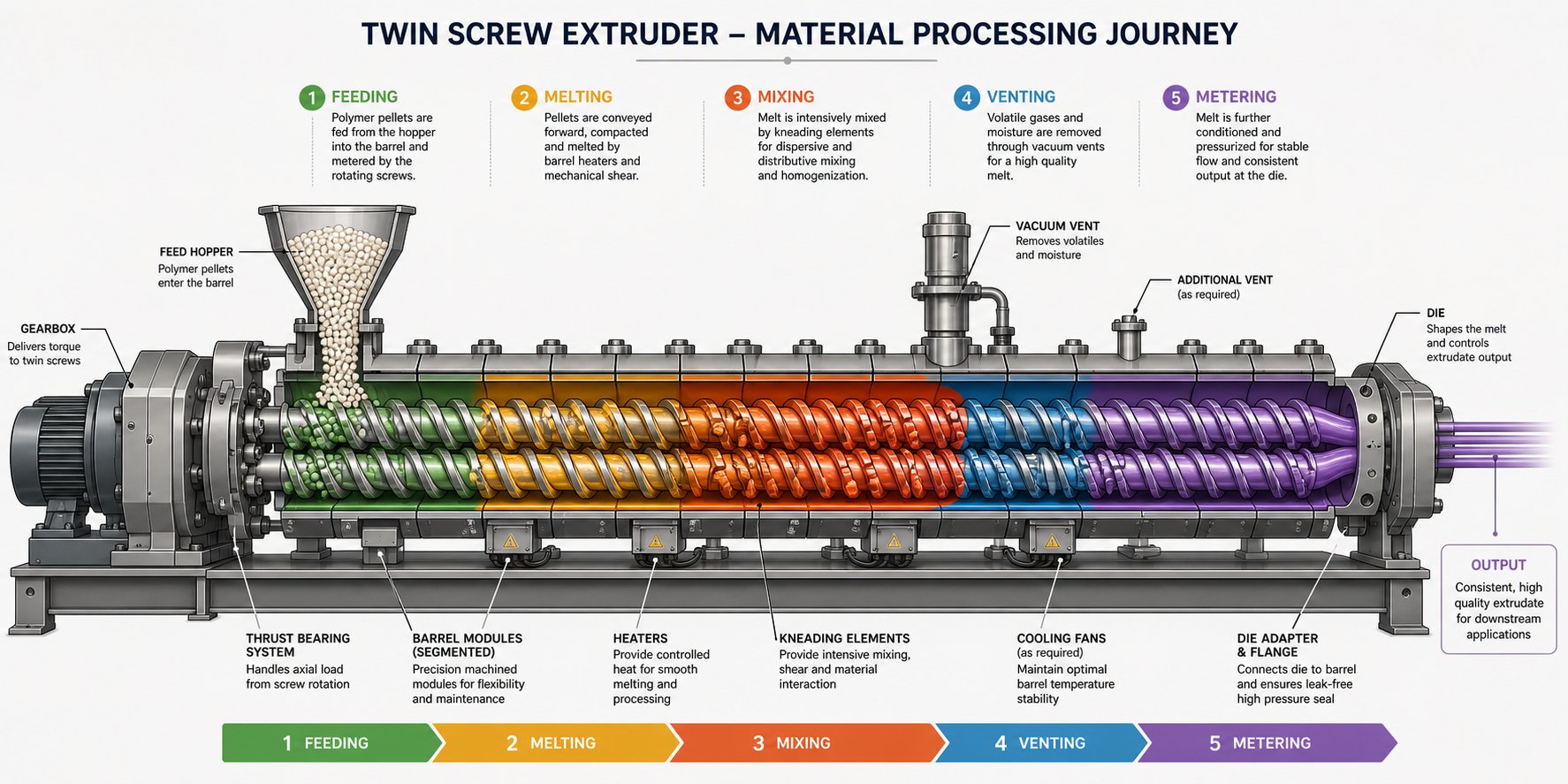
Screw elements, barrel zones, feeding strategies, process parameters—each has been examined in isolation. But material does not experience these systems one at a time. A pellet entering the feed throat undergoes a continuous, overlapping transformation where transport, melting, mixing, devolatilization, and pressurization blend into a single unbroken journey. Following that pellet from hopper to die reveals how every principle discussed so far converges in practice.
From Feed Throat to Melting Zone
Imagine a handful of polymer pellets dropping from a loss-in-weight feeder into the feed throat of a plastic twin screw extruder. They tumble onto large-pitch conveying elements that are deliberately underfilled—the starve-fed condition that decouples throughput from screw speed. At this stage, the screws act purely as conveyors. The pellets are solid, the screw channels are partially empty, and barrel heaters are warming the surrounding metal but have not yet transferred meaningful energy into the material.
As the conveying elements carry pellets forward, pitch decreases and fill level rises. The pellets compress against each other and against the heated barrel wall. Heat conduction from the barrel begins softening the outer surface of each pellet, but this alone is not enough to achieve full melting. The real transition happens when the material reaches the first set of kneading blocks. Here, the staggered elliptical discs force the compressed pellets through narrow gaps between the disc tips and the barrel bore. Viscous shear—the internal friction generated as softened polymer is deformed at high strain rates—converts mechanical energy directly into heat within the polymer mass itself. This viscous dissipation, combined with barrel conduction, completes the solid-to-melt transition over a relatively short axial distance.
The quality of this melting step is critical. If unmelted solid fragments survive past the kneading zone, they create inconsistencies in every downstream operation—poor filler wetting, uneven additive distribution, and pressure instabilities at the die. A well-designed twin screw extruder plastic configuration ensures complete melting before the material advances to the mixing section.
Mixing and Homogenization Through the Process Section
With the polymer fully molten, the process enters its most transformative phase. The melt flows into intensive kneading and mixing zones where the real compounding work happens. Pigments are dispersed to primary particle size under high shear. Stabilizers, coupling agents, and processing aids are distributed uniformly throughout the matrix. For an extruder for polymer blends, this is where immiscible phases are broken into fine droplets and stabilized by compatibilizers—the elongational and shear fields generated by kneading blocks provide the stress needed to overcome interfacial tension.
Downstream of the primary mixing zone, a reverse-pitch element or 90-degree kneading block creates a melt seal—a fully filled plug of polymer that acts as a pressure barrier. Directly beyond this seal, large-pitch conveying elements create a low-fill, low-pressure zone beneath an open vent port. Volatiles that were locked inside the solid pellets—moisture, residual monomer, trapped air—now flash off the exposed melt surface and escape through the vent. Vacuum-assisted venting pulls the partial pressure even lower, driving volatile levels down to fractions of a percent.
If the formulation calls for fillers or reinforcing fibers, a side stuffer introduces them into the already-molten stream at a combination barrel located after the vent. Glass fibers, mineral fillers, or heat-sensitive additives enter a gentle polymer extruder environment—the melt is fully developed, shear is moderate, and the downstream mixing elements are configured with narrow-disc kneading blocks or gear-type distributive elements that incorporate the additives without excessive attrition. This staged approach protects fiber length and prevents degradation of sensitive components that would not survive the initial melting zone.
Metering and Die Discharge
The final conveying section shifts the extruder's role from formulation development to pressure generation. Tight-pitch conveying elements compress the now-homogeneous melt, building the stable pressure needed to force material through the die at a consistent volumetric rate. Any fluctuation in this metering zone—caused by vent flooding, inconsistent feed rate, or worn screw elements—translates directly into dimensional variation in the final product.
Die geometry determines what emerges on the other end. A strand die produces spaghetti-like ropes of compound that are water-cooled and chopped into pellets—the most common output for a twin screw plastic extruder used in compounding. A sheet die spreads the melt into a flat film or slab. A profile die shapes it into window frames, decking boards, or cable channels. A pipe die forms hollow tubes calibrated to precise wall thicknesses. In every case, the die is not just a shaping tool—it is the final restriction that determines backpressure throughout the entire upstream process.
Unlike single screw extruders, every processing stage in a twin screw extruder can be independently optimized through modular screw and barrel configuration—melting intensity, mixing type, devolatilization efficiency, and metering stability are each controlled by distinct, interchangeable elements rather than by a single fixed screw geometry.
This end-to-end modularity is the twin screw extruder working principle in its most practical form. The material's journey is not a single event but a designed sequence of transformations—each governed by specific elements, each tunable without disrupting the others. Yet behind every one of those transformations lies a question of energy: how much mechanical work enters through the screws, how much heat transfers through the barrel, and how that total energy input determines whether the final product meets specification or falls short.
Energy Balance in a Twin Screw Extruder Machine
Every transformation described in the material journey—melting, mixing, devolatilization, metering—requires energy. But where does that energy come from, and how much of each source actually reaches the polymer? The answer defines whether your compound exits the die perfectly homogenized or thermally degraded. Two quantities capture the full picture: specific mechanical energy and specific thermal energy. Together, they form the energy balance that governs every aspect of product quality in twin screw extrusion.
Specific Mechanical Energy and Viscous Dissipation
Specific mechanical energy (SME) is the mechanical work input per unit mass of material processed, expressed in kilowatt-hours per kilogram (kWh/kg). It is derived from three measurable quantities: motor power, screw speed, and mass throughput. In practical terms, SME tells you how much rotational energy from the drive motor is transferred through the screws and into the compound during processing.
But how does rotational motion become heat inside a polymer melt? Through viscous dissipation. As the screws rotate, they force molten polymer through narrow gaps—between flight tips and the barrel wall, between kneading disc edges and the bore, and through the intermeshing zone where the two screws nearly touch. The polymer resists this deformation because of its viscosity, and that resistance converts mechanical energy directly into thermal energy within the melt itself. The higher the viscosity and the greater the shear rate, the more heat is generated internally.
This is not a minor heat source. In most compounding operations on a screw extruder, viscous dissipation is the primary melting mechanism—not the barrel heaters. Research on energy consumption in polymer extrusion confirms that the mechanical energy of the rotating screw is the major source of input energy, particularly in the feed and compression zones, where frictional heat between solids generates energy rapidly and homogeneously. Barrel heaters initiate the process by softening the pellet surfaces, but the bulk of the solid-to-melt conversion is driven by shear.
Screw configuration directly determines SME input. More kneading blocks—especially at high stagger angles—impose greater shear on the melt and demand more motor torque, raising SME. Conversely, a mild screw with predominantly conveying elements transfers less mechanical energy. A case study on masterbatch compounding demonstrated this vividly: a 26-mm extruder achieved an optimized SME of 0.083 kWh/kg, producing a homogeneous, pelletizable product. When the process was scaled to a 92-mm twin screw extruder machine using the same operating conditions, SME dropped to just 0.026 kWh/kg—a 69% reduction—resulting in unmelted pellets discharging through the diverter valve. Only after redesigning the screw and adjusting the feeding configuration to bring SME back up to 0.086 kWh/kg did the process recover and deliver a fully homogeneous melt.
Specific Thermal Energy and Barrel Temperature Control
Specific thermal energy (STE) represents the heat energy transferred to (or removed from) the material through the barrel wall per unit mass. Barrel heaters add STE when they raise the polymer temperature above what viscous dissipation alone would achieve. Barrel cooling—typically through circulating water or oil in channels surrounding each barrel section—removes STE when viscous dissipation generates more heat than the process target requires.
Here is the part that surprises many operators: in a well-designed compounding process, the barrel heaters often contribute a relatively small fraction of the total energy input. Their role shifts from being a primary heat source to functioning as a temperature-regulation tool—trimming the thermal profile rather than driving it. At moderate to high screw speeds, viscous dissipation can generate enough heat to overshoot the target melt temperature, and the barrel cooling system actually removes energy from the process. In that scenario, STE becomes negative—the barrel is a heat sink, not a heat source.
Experimental work comparing energy contributions in both single and twin screw extruders shows that increasing barrel set temperatures can reduce motor energy demand slightly—because a hotter barrel lowers melt viscosity and thus reduces shear stress—but simultaneously raises heater energy consumption. The net effect on total specific energy consumption is not always intuitive, which is why treating SME and STE as independent, additive contributions gives process engineers a clearer picture than monitoring barrel temperature alone.
Why the Energy Balance Determines Product Quality
The total energy input to the polymer—SME plus STE—controls three outcomes that define product quality:
- Melt temperature: The final melt temperature is a direct consequence of the energy balance, not simply the barrel setpoint. Two processes with identical barrel profiles can produce very different melt temperatures if their SME inputs differ.
- Degree of mixing: Higher SME generally means more intensive shear history—better dispersion, finer morphology in blends, and more complete wetting of fillers. But beyond a threshold, additional energy input degrades heat-sensitive polymers rather than improving them.
- Thermal degradation risk: Excessive total energy—whether from aggressive kneading, too-high barrel temperatures, or extended residence time—pushes melt temperature beyond the polymer's stability window, causing chain scission, discoloration, or crosslinking.
The scaleup case study cited above illustrates this powerfully. At the pilot scale (40-mm extruder), an initial SME of only 0.055 kWh/kg—about 34% lower than the laboratory reference—produced phase separation and poor mixing so severe that the masterbatch could not even be pelletized. Adjustments to the screw design, temperature profile, and screw speed brought SME back to 0.079 kWh/kg, and the process immediately stabilized. The energy balance was the root cause, and matching SME across scales was the solution.
This principle extends beyond scaleup. Day-to-day process control on any twin screw extruder machine benefits from SME monitoring. If SME drifts upward at constant parameters, it may indicate increased material viscosity from a raw-material lot change, worn screw elements altering clearances, or a feed rate disruption. If SME drops, the cause could be lubrication effects from additives, reduced fill level, or a barrel heater malfunction changing the thermal contribution. Tracking SME turns extruder technology from a reactive operation—adjusting when defects appear—into a proactive one where deviations are caught before they reach the pelletizer.
Optimizing the energy balance—not simply maximizing throughput—is the key to successful twin screw extrusion process control, because it is the total energy input per kilogram, not any single process parameter, that ultimately determines melt temperature, mixing quality, and product consistency.
With the energy balance as the unifying framework, every upstream decision—screw configuration, barrel layout, feed strategy, RPM selection—connects to a measurable outcome. The remaining question is how all of these principles translate into real-world processing lines, across the diverse industries where twin screw extruders operate every day.
Industrial Applications of Twin Screw Compounding Extruders
Energy balance, modular screw design, starve feeding, devolatilization—these principles are not academic exercises. They are the engineering foundations behind processing lines that run around the clock in dozens of industries worldwide. The versatility of the twin screw extruder working principle means the same core machine architecture solves radically different manufacturing challenges depending on how it is configured. Here is where theory meets production reality.
Polymer Compounding and Masterbatch Production
The compounding twin screw extruder is the backbone of the plastics industry. Every time an engineering plastic gains impact resistance from rubber toughening, flame retardancy from mineral additives, or color from pigment concentrates, a twin screw compounding extruder almost certainly did the mixing. The reasons trace directly to the principles covered earlier: intensive dispersive and distributive mixing from modular kneading elements, self-wiping geometry that prevents degradation, and starve-fed operation that decouples throughput from mixing intensity.
Masterbatch production—where pigments, UV stabilizers, or processing aids are concentrated into a carrier resin at loadings of 20% to 70%—pushes these capabilities to their limits. Color masterbatch for thin film applications demands dispersive mixing performance that breaks pigment agglomerates down to primary particle size, requiring aggressive kneading block configurations with high stagger angles and carefully controlled SME. Filled compounds—calcium carbonate at 60% to 80% loading, glass-fiber-reinforced polyamides, talc-filled polypropylene—rely on side-stuffer feeding and downstream barrel sections to incorporate solids gently into the melt without destroying fiber length or generating excessive wear.
Plastic Recycling and Pelletizing
Recycling is where the compounding extruder's devolatilization and mixing flexibility prove indispensable. Post-industrial regrind—edge trim from film lines, runner scrap from injection molding—re-enters the compounding process with relatively predictable composition, making it well-suited for twin screw processing. The screw extruder granulator configuration removes residual moisture through multi-stage vacuum venting, disperses minor contaminants, and produces uniform pellets via strand or underwater pelletizing systems.
Post-consumer recycling (PCR) presents greater challenges. Contamination levels are higher, polymer types may be mixed, and residual volatiles from inks, adhesives, and food residues require aggressive devolatilization. As industry experts at Leistritz note, the starve-fed co-rotating twin screw extruder excels at mixing and volatile removal but is not a high-pressure pump—filtration-intensive PCR streams often require tandem systems pairing a twin screw mixer with a single screw pressure generator or gear pump for fine-screen filtration. Understanding these boundary conditions prevents costly misapplication of the technology.
The following list captures the major application categories where these machines operate today:
- Polymer compounding: engineering plastics, impact-modified blends, thermoplastic elastomers
- Masterbatch production: color, additive, and filler concentrates
- Filled and reinforced plastics: glass fiber, carbon fiber, mineral-filled compounds
- Reactive extrusion: in-situ polymerization, grafting, controlled degradation, crosslinking
- Plastic recycling and pelletizing: post-industrial and post-consumer reclaim with devolatilization
- Pipe and profile extrusion: PVC and polyolefin pipes, window profiles (counter-rotating configurations)
- Sheet extrusion: PET, PLA, and multi-layer sheet lines
- Food and pharmaceutical processing: textured proteins, hot-melt extrusion for drug delivery, snack and cereal production
Emerging and Specialized Applications
Reactive extrusion represents one of the fastest-growing application areas. Instead of simply mixing pre-made ingredients, the extruder becomes a continuous chemical reactor—carrying out polymerization, grafting, or controlled crosslinking reactions inside the barrel. Twin screw extruders provide the precise temperature control, tunable residence time, and intensive mixing that these reactions demand, all in a continuous process that eliminates the batch-to-batch variability of reactor vessels.
Bio-based and biodegradable polymers—PLA, PHA, starch blends, and natural fiber composites—are another expanding frontier. These materials are typically shear- and temperature-sensitive, requiring careful energy balance management to compound effectively without degradation. The modularity of twin screw systems lets engineers dial back kneading intensity and optimize barrel cooling in ways that fixed-geometry equipment cannot.
At the smallest scale, a laboratory twin screw extruder enables R&D teams to develop new formulations with as little as a few hundred grams of material. A benchtop twin screw extruder—often with screw diameters of 12 to 27 mm—replicates the full modular architecture of production machines, including interchangeable screw elements, multi-zone barrel heating, and gravimetric feeding. Micro-compounders like the Xplore series push this even further, allowing researchers to test formulations with just grams of material before committing to pilot-scale trials. The benchtop twin screw extruder bridges the gap between lab-scale discovery and production-scale implementation, making it an essential tool for accelerating material development cycles.
Across all of these applications—from high-volume compounding lines to small-batch R&D setups—the screw and barrel are the components that directly execute the working principle. They are also the components most subject to wear. For extrusion manufacturers, recycling plants, and technical teams seeking screw barrel support across pipe, profile, sheet, pelletizing, and recycling processing lines, suppliers like NANHAIYA provide precision-manufactured replacement components that help maintain extruder performance over the long term.
That leads to a final, deeply practical question: how do you know when your screw and barrel components are degrading, and what can you do to keep the twin screw extruder working principle performing as designed?
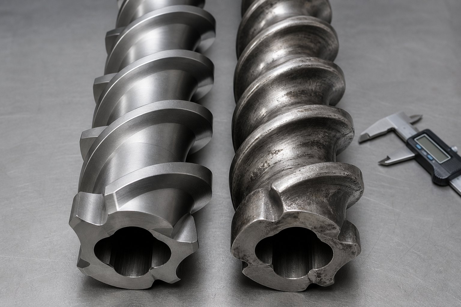
Selecting and Maintaining Twin-Screw Extruder Machine Screw and Barrel Components
Every principle covered in this article—drag flow, self-wiping, dispersive mixing, energy balance—depends on precise clearances between screw elements and the barrel bore. When those clearances open up due to wear, the physics degrade quietly at first and then catastrophically. A worn screw flight no longer wipes the barrel wall cleanly. A widened bore allows backflow through gaps that should be sealed. The twin screw extruder working principle does not fail all at once; it erodes, one tenth of a millimeter at a time.
Matching Screw and Barrel Materials to Your Process
What wears your screws and barrels fastest? The answer depends entirely on what you are processing. A double screw extruder machine running unfilled polyolefins at moderate speeds may deliver years of service on standard nitrided steel components. Add 40% glass fiber to that formulation, and you could be replacing screw elements within months if the metallurgy is not matched to the application.
Three material categories cover most twin screw extruder manufacturers' standard offerings:
| Material / Treatment | Hardness Range | Best Suited For | Limitations |
|---|---|---|---|
| Nitrided steel (e.g., 38CrMoAlA) | HV 900–1,000 (surface layer 0.5–0.8 mm) | Unfilled polymers, color masterbatch, general compounding with low filler content | Limited abrasion resistance; surface layer wears through under heavy filler loading |
| Bimetallic liners / overlay welding | HRC 58–65 | Moderate to high filler levels (CaCO3, talc), PVC with calcium carbonate, recycling streams with contamination | Higher cost than nitriding; requires proper bonding to prevent delamination |
| Tungsten carbide coatings (HVOF or PTA) / solid carbide elements | Up to HRC 70 | Highly abrasive compounds: glass fiber above 30%, mineral-filled engineering plastics, ceramic-loaded formulations | Highest cost; brittle under impact if not properly supported |
Corrosion adds another dimension. Processing PVC, fluoropolymers, or flame-retardant compounds releases acidic byproducts—hydrochloric acid from PVC, for instance—that attack carbon steel from the inside out. Nickel-based bimetallic barrel liners resist this chemical attack far better than nitrided surfaces, which is why virtually every twin-screw extruder manufacturer specifies bimetallic construction for PVC processing lines.
The key principle is straightforward: match your metallurgy to the most demanding ingredient in your formulation. A compound that is 95% polyethylene and 5% titanium dioxide still wears differently than neat polyethylene. Underspecifying barrel or screw materials to save on upfront cost almost always costs more in downtime and replacement frequency.
Signs of Screw and Barrel Wear and Their Impact
Wear does not announce itself with an alarm. It shows up as gradual, often puzzling changes in process behavior—shifts that operators sometimes attribute to raw material variation, ambient temperature changes, or equipment quirks before recognizing the real cause. As wear specialists at Xtrutech observe, abrasive wear is the most common type in twin screw extruders, rounding the sharp machined corners of screw and kneading elements until they appear smooth and polished. The position of heaviest wear typically starts at the last set of feed screws and first kneading elements, then migrates further downstream as the damage progresses—effectively shortening the extruder's useful mixing length.
Watch for these warning signs:
- Declining output at constant process parameters: Worn flights and widened barrel clearances allow more backflow, reducing net forward conveying. You are running the same RPM and feed rate, but less material reaches the die.
- Increased melt temperature: As clearances widen, the polymer recirculates more within the screw channels, absorbing additional shear energy. Melt temperature creeps upward even though barrel setpoints have not changed.
- Poor dispersion quality: The self-wiping mechanism depends on tight tolerances. Once screw element OD shrinks or barrel ID grows beyond roughly 0.3–0.4 mm of additional clearance, the wiping action degrades and dead zones reappear—leading to visible streaks, undispersed pigment clusters, or unincorporated filler agglomerates in the final product.
- Higher specific energy consumption: The motor works harder to compensate for lost conveying efficiency, driving up kWh/kg even though throughput may actually be declining.
- Increased pressure fluctuation at the die: Worn metering-zone elements cannot build consistent pressure, producing surging that shows up as dimensional variation in pellets, sheet, or profiles.
A practical maintenance approach involves regular dimensional checks—measuring screw element outer diameter and barrel bore inner diameter at scheduled intervals. Industry maintenance data suggests that proactive monitoring programs can reduce operating costs by 20% to 30% compared to reactive replacement strategies. Monthly bore inspections—feasible with clamshell barrel designs or bore gauges—catch wear in its early stages, giving you time to order replacement parts before production quality suffers.
Partnering with Reliable Screw and Barrel Suppliers
Understanding the twin screw extruder working principle is only half the equation. Maintaining the physical components that execute that principle—at the tight tolerances required for self-wiping, efficient conveying, and consistent mixing—demands precision-manufactured replacement parts sourced from suppliers who understand twin screw geometry at a detail level.
When evaluating a twin-screw extruder manufacturer or aftermarket parts supplier, consider several factors beyond unit price:
- Dimensional accuracy: Screw elements and barrel bores must match OEM tolerances. Even small deviations compromise self-wiping clearances and alter the flow mechanics the entire process depends on.
- Metallurgical options: A reliable supplier offers the full range—nitrided, bimetallic, and carbide-coated solutions—so you can match the component to your specific process demands rather than settling for a one-size-fits-all option.
- Application breadth: Processing lines vary enormously. Pipe, profile, sheet, pelletizing, and recycling applications each impose different wear patterns and require components engineered for those specific conditions.
For extrusion manufacturers and technical teams seeking screw barrel support across these diverse processing lines, NANHAIYA's plastic extruder machine and screw barrel solutions provide a practical resource—covering double screw extruder machine configurations for pipe, profile, sheet, pelletizing, recycling, and general plastic processing applications. Having a dependable supply partner means that when wear monitoring flags a developing problem, replacement components are available before production quality degrades.
The twin screw extruder working principle is elegant in theory and powerful in practice. But it only delivers consistent results when the hardware executing it—every screw element, every barrel section, every clearance—remains within the design tolerances that make self-wiping, efficient mixing, and precise energy balance possible. Invest in understanding the principle. Then invest equally in maintaining the components that bring it to life.
Frequently Asked Questions About Twin Screw Extruder Working Principle
1. What is the basic working principle of a twin screw extruder?
A twin screw extruder operates by rotating two intermeshing screws inside a figure-eight-shaped heated barrel. Material is conveyed forward through drag flow generated by screw rotation against the barrel wall, while pressure flow acts in the opposite direction at restrictions like kneading blocks or the die. The net movement is the balance of these two forces. Melting occurs primarily through viscous dissipation — the internal friction created as polymer is sheared between screw elements and the barrel — supplemented by conducted heat from barrel heaters. The intermeshing geometry forces material to transfer between screws in a figure-eight path, producing intensive distributive and dispersive mixing that single screw designs cannot replicate. Modular screw elements and barrel sections allow each processing stage — feeding, melting, mixing, devolatilization, and metering — to be independently configured and optimized for a specific formulation.
2. What is the difference between co-rotating and counter-rotating twin screw extruders?
Co-rotating twin screw extruders have both screws turning in the same direction, creating a figure-eight material flow path with high shear and excellent self-wiping. They operate at 300 to 1,200 RPM and dominate compounding, masterbatch, and reactive extrusion applications due to superior mixing intensity. Counter-rotating extruders rotate screws in opposite directions, forming closed C-shaped chambers that convey material like a positive displacement pump. They run at much lower speeds (5 to 80 RPM), generate stable pressure with minimal shear, and are preferred for thermally sensitive materials like PVC in pipe and profile extrusion. The choice depends on whether your process prioritizes intensive mixing (co-rotating) or gentle, pressure-stable conveying (counter-rotating).
3. Why are twin screw extruders starve-fed instead of flood-fed?
Starve feeding uses a gravimetric or volumetric feeder to meter material into the barrel below the screw's maximum conveying capacity, deliberately leaving screw channels partially filled. This decouples throughput from screw speed — an operator can increase RPM for more intensive mixing without changing output rate, or adjust feed rate without altering shear input. In contrast, flood-fed single screw extruders tie output directly to screw speed, limiting independent process control. Starve feeding also reduces die pressure fluctuations and prevents the overfilling and surging common in gravity-fed systems. This independent control of feed rate and screw speed is the operational foundation that gives twin screw extruders their exceptional process flexibility across diverse compounding and extrusion tasks.
4. How do kneading block stagger angles affect mixing in a twin screw extruder?
Kneading blocks consist of stacked elliptical discs offset at specific angles, and that stagger angle is the primary variable controlling mixing behavior. A 30-degree stagger angle maintains forward conveying while gently splitting and recombining the melt for distributive mixing. A 60-degree angle reduces conveying and increases shear for moderate dispersive action. A 90-degree (neutral) angle eliminates net forward conveying entirely, trapping material under intense shear to break apart agglomerates — ideal for dispersive mixing of pigments and fillers. Disc width also matters: narrower discs create more frequent flow disruptions and stronger dispersive forces, while wider discs produce smoother, gentler mixing. For screw barrel solutions tailored to specific kneading configurations, suppliers like NANHAIYA at nhyscrews.com offer components matched to diverse compounding requirements.
5. What are the signs of screw and barrel wear in a twin screw extruder?
Worn screw elements and barrel bores degrade extruder performance gradually before becoming obvious. Key warning signs include declining output at constant process parameters (widened clearances allow more backflow), rising melt temperature despite unchanged barrel setpoints (polymer recirculates and absorbs extra shear energy), poor dispersion quality with visible streaks or undispersed particles (self-wiping loses effectiveness beyond roughly 0.3 to 0.4 mm of additional clearance), higher specific energy consumption as the motor compensates for lost conveying efficiency, and increased die pressure fluctuation causing dimensional variation in pellets or profiles. Regular dimensional checks of screw element outer diameter and barrel bore inner diameter catch wear early. Proactive monitoring programs can reduce operating costs by 20 to 30 percent compared to waiting for visible product defects.
Written by
Nanhaiya Technical Team
Zhoushan Nanhaiya Plastic Machinery Co., Ltd.
The Nanhaiya technical team supports screw and barrel manufacturing projects through application review, technical communication, custom manufacturing coordination, and production and quality control.
Discuss Your Application
Related Articles
More insights on screw barrel technology and plastics processing.

What Nobody Tells You About Screw Barrel For Plastic Machine Design
Oct 10, 2026
Learn how screw barrel for plastic machine design affects melt quality, throughput, and wear life. Covers geometry, resin matching, troubleshooting, and sourcing.
Read Article
Single Screw Extruder for Sheet: Stop Guessing, Start Specifying
Oct 9, 2026
Learn how to specify a single screw extruder for sheet production. Covers screw geometry, resin-specific processing, troubleshooting, and maintenance best practices.
Read Article
PE Pipe Extruder Machine: What Datasheets Won't Tell You
Oct 9, 2026
Learn how a PE pipe extruder machine works, key specs explained, material grade selection, maintenance tips, and buyer guidance beyond the datasheet.
Read ArticleLooking for something else?
Search by material, symptom or product and jump straight to the relevant page.
These are navigation suggestions based on keyword matching — not a quotation, not a delivery commitment, and not a substitute for engineering review. Final specification is confirmed by our engineers against your drawings and processed material.
Need help with screw barrel selection?
Share your machine model, processed material and application. Our team can help with pricing and technical support.