

How a Twin Screw Extruder Works at Its Core
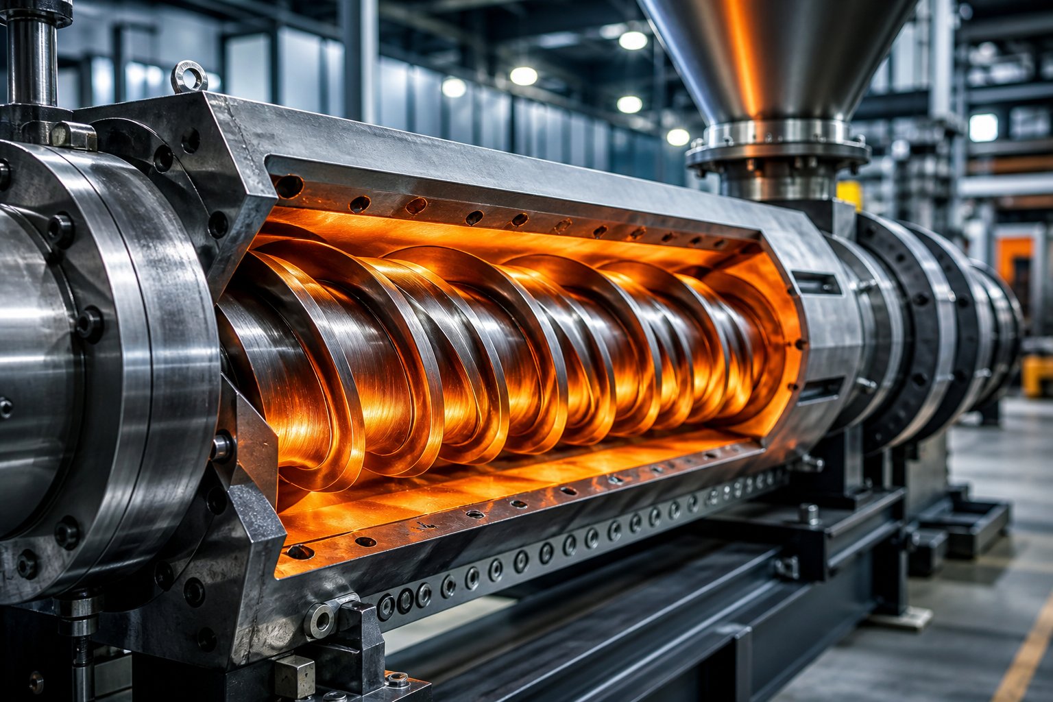
Imagine two helical screws rotating side by side inside a heated barrel, their flights interlocking like precisely machined gears. That interaction is the heartbeat of every twin screw extruder, and understanding it separates competent operators from engineers who can truly optimize a process.
A twin screw extruder works by rotating two intermeshing screws inside a figure-eight-shaped barrel bore to convey, melt, mix, and shape materials through a combination of controlled shear forces and thermal energy, producing a homogeneous output suitable for compounding, reactive processing, and devolatilization.
Defining the Twin Screw Extruder
At its simplest, the twin-screw extruder is a machine built around positive displacement. Raw material enters the barrel, and the rotating twin screws push it forward while compressing, shearing, and heating it into a uniform melt. The barrel's figure-eight bore geometry keeps the two screws closely intermeshed, so every rotation forces material through a narrow gap between the screws and the barrel wall. This generates the shear stress needed to break down pellets, disperse additives, and homogenize the final compound.
When people ask about extruders meaning in a processing context, the answer always centers on this principle: converting raw feedstock into a continuous, shaped output. A twin screw extrusion system simply does it with far greater control than a single-screw design ever could.
Why Twin Screw Technology Stands Apart
A single screw extruder relies on friction between the material and barrel wall to generate forward movement. A twin screw extruder, by contrast, uses the intermeshing action of two screws to create a self-wiping effect that continuously scrapes material from screw surfaces and barrel walls. This eliminates stagnant zones where heat-sensitive polymers would degrade.
The practical advantages stack up quickly:
- Independent control of throughput and screw speed — you can adjust mixing intensity without changing production rate.
- Modular screw and barrel design — individual elements slide onto splined shafts, letting engineers reconfigure the entire screw profile for a new formulation.
- Superior distributive and dispersive mixing — the open intermesh zone in co-rotating systems forces material through elongational flow fields that single-screw machines simply cannot replicate.
These capabilities explain why twin screw extrusion dominates compounding, reactive processing, and volatile removal across the polymer industry. Yet the real engineering depth lies beneath these headline benefits — in the specific screw element geometries and barrel configurations that make each process possible.
Types of Twin Screw Extruders Organized by Design
Not every twin screw extruder behaves the same way. Two machines can share the same barrel diameter yet produce wildly different shear profiles, pressure characteristics, and mixing behaviors — all because of three fundamental design choices. Understanding this classification hierarchy is the fastest way to match an extruder to a specific process challenge.
Intermeshing Versus Non-Intermeshing Configurations
The first distinction is how closely the twin screws interact. In an intermeshing design, the flights of one screw penetrate into the channel of its neighbor. This tight engagement creates positive conveying — material cannot simply spin in place — and enables a self-wiping action where each screw continuously scrapes its partner clean.
Non-intermeshing extruders, by contrast, position the screws far enough apart that their flights never overlap. The distance between screw axes equals or exceeds the sum of their outer radii. Material moves through wider, more open channels with lower shear and less precise forward displacement. You'll find non-intermeshing configurations in applications that demand gentle handling and controlled material exchange rather than aggressive dispersion.
Co-Rotating and Counter-Rotating Twin Screw Extruders
Rotation direction changes everything about how material flows through the intermesh zone.
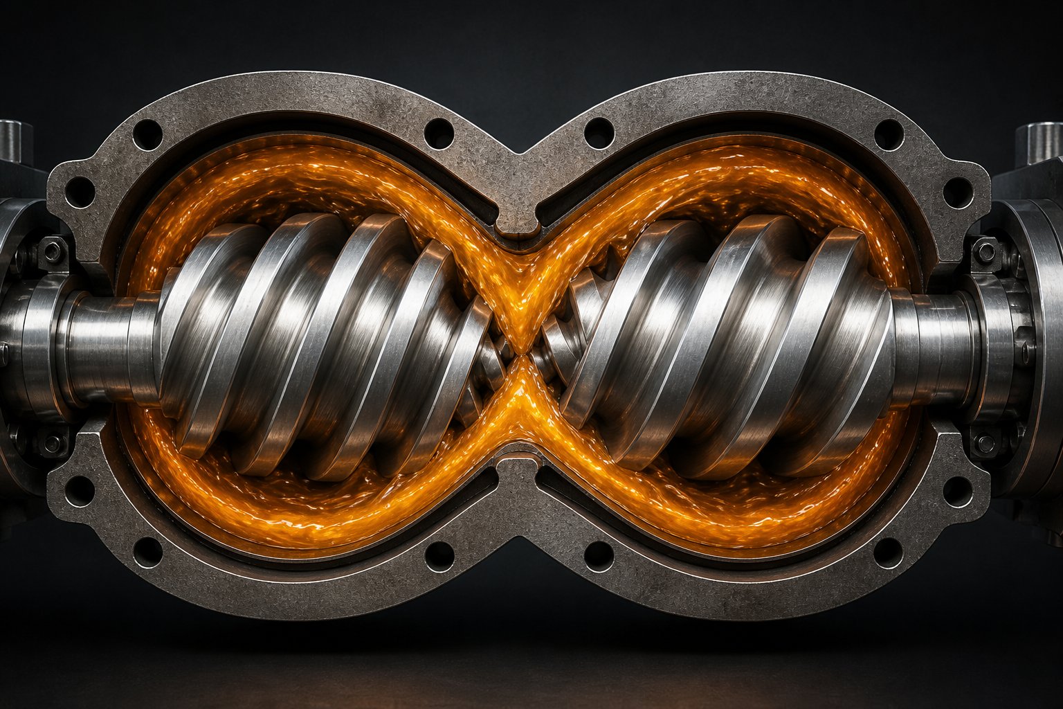
A co-rotating twin screw extruder turns both screws in the same direction. At the intermesh point, material transfers from one screw to the other in a figure-eight path, passing through elongational flow fields that deliver outstanding distributive and dispersive mixing. This open-channel transfer makes co-rotating systems the dominant choice for polymer compounding, nanocomposite preparation, and reactive extrusion.
A counter-rotating design spins the screws in opposite directions, forming enclosed C-shaped chambers between the flights. These sealed pockets act almost like individual pumps, generating high pressure and positive displacement with minimal backflow. The trade-off? Less cross-channel mixing. That's exactly why counter-rotating extruders excel in shaping operations — think PVC pipe and profile extrusion — where consistent pressure at the die matters more than intensive blending. When comparing a co rotating and counter rotating twin screw extruder, the choice ultimately hinges on whether your process is mixing-limited or pressure-limited.
Parallel and Conical Screw Geometries
The final branch of the classification tree addresses physical shape.
A parallel twin screw extruder maintains a uniform screw diameter from feed end to discharge. This consistent geometry is the foundation of modular element design: engineers can slide conveying elements, kneading blocks, and mixing discs onto a splined shaft in any sequence. Parallel configurations dominate high-throughput compounding and research applications where process flexibility is paramount.
A conical twin screw extruder tapers its screws from a larger diameter at the feed zone to a smaller diameter at the outlet. This taper creates natural compression as material moves forward — no change in screw pitch required. Conical designs pack large feed openings and high torque capacity into a compact footprint, making them well-suited for processing bulky or high-viscosity materials at medium throughput rates.
| Configuration | Rotation | Screw Geometry | Self-Wiping Capability | Shear Intensity | Typical Applications |
|---|---|---|---|---|---|
| Intermeshing | Co-rotating | Parallel | Excellent | High | Polymer compounding, reactive extrusion, masterbatch, nanocomposites |
| Intermeshing | Co-rotating | Conical | Good | Medium-High | Lab-scale micro-compounding, R&D formulation trials |
| Intermeshing | Counter-rotating | Parallel | Moderate | Medium | PVC pelletizing, cable coating, specialty compounding |
| Intermeshing | Counter-rotating | Conical | Moderate | Medium | PVC pipe, profile extrusion, rigid and flexible sheet |
| Non-intermeshing | Counter-rotating | Parallel | None | Low | Gentle mixing, controlled reactive extrusion, devolatilization |
Every row in this table represents a distinct set of transport physics. The screw geometry determines compression behavior, rotation direction controls mixing versus pumping emphasis, and meshing type dictates how tightly the process is controlled. These three variables interact — and the next layer of complexity lies in the individual screw elements that populate each configuration.
Modular Screw Elements That Control Mixing and Conveying
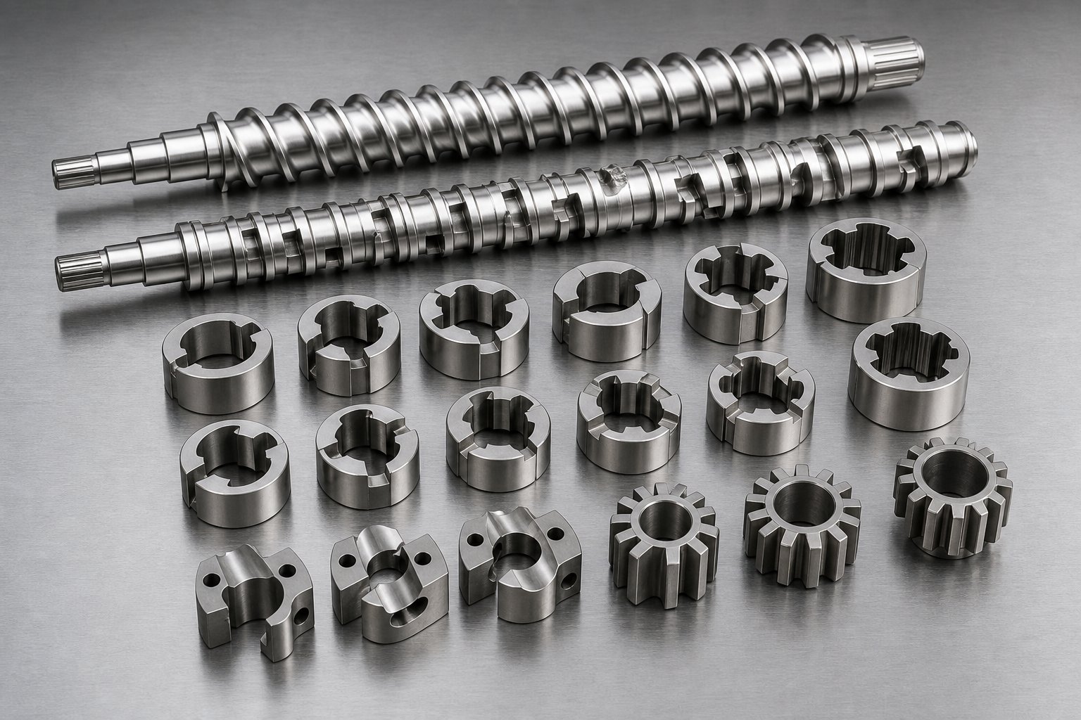
Here is where twin screw extruder working becomes genuinely customizable. Unlike single-screw machines with monolithic screw designs, a modern extruder twin screw system uses a modular architecture: individual screw elements slide onto a splined shaft, locked in place by keyways and a shaft-end nut. Change the element sequence, and you fundamentally change how material is conveyed, melted, mixed, and pressurized.
Think of it like building blocks on a steel backbone. Each element has a specific geometry designed to perform a specific task. Engineers assemble these elements into a complete screw profile tailored to the polymer, filler system, and downstream requirements. Below is a breakdown of every major element type you'll encounter in an extruder twin screw configuration.
- Forward conveying elements — helical flights that move material downstream; available in varying pitches to control conveying speed.
- Reverse conveying elements — left-handed flights that push material upstream, creating restriction and building pressure.
- Forward-staggered kneading blocks (30° and 60°) — disc-shaped elements that provide mixing while still conveying material forward.
- Neutral kneading blocks (90°) — disc elements that deliver maximum dispersive mixing with no forward conveying action.
- Reverse kneading blocks — counterclockwise-staggered discs that pump material backward for the most aggressive shear input.
- Gear mixing elements (GME) — toothed wheels that split and recombine melt streams for distributive mixing at low shear.
- Toothed mixing elements (ZME/TME) — multi-row tooth profiles that repeatedly divide and recombine material for homogenization.
- Blister rings — solid cylindrical restrictions that create melt seals for upstream venting zones.
Conveying Elements and Their Flight Geometry
Every extruder screw profile starts and ends with conveying elements. Their helical flights grab incoming feedstock and push it downstream — straightforward in concept, but pitch selection creates real engineering leverage.
A wide-pitch conveying element moves material quickly, keeping the channel partially filled and residence time short. A tight-pitch element slows things down, increasing fill level and giving downstream zones more time to act on the material. In a starve-fed co-rotating system, you'll often see wide-pitch elements near the feed port transitioning to progressively tighter pitches as material approaches the first melting zone.
Reverse conveying elements flip the helix direction. Instead of moving material forward, left-handed flights push it backward, creating a dam effect. Upstream fill level rises, pressure builds, and the material is forced through the narrow clearance between flight tip and barrel wall. This restriction is essential — it's how engineers establish melt seals that prevent vent ports from flooding, and it increases residence time in zones where additional mixing or melting is needed.
Kneading Blocks and Stagger Angle Effects
If conveying elements are the transport workhorses of a plastic extruder screw, kneading blocks are the mixing engines. Each block consists of multiple disc-shaped lobes stacked along the shaft, with each disc offset from its neighbor by a fixed stagger angle. That angle — and the width of each disc — determines how aggressively the block works the polymer.
Here's the engineering rationale. When a kneading block rotates, polymer can either flow around a disc to the next one or squeeze past the narrow gap between the disc tip and the barrel wall. The tip-to-barrel clearance is the highest-shear zone in the entire extruder. Wider discs force more material through that gap, increasing energy input and melt temperature.
Stagger angle controls how much forward conveying the block contributes:
| Stagger Angle | Conveying Action | Mixing Character | Typical Use |
|---|---|---|---|
| 30° forward | Strong forward conveying | Gentle distributive mixing | Initial melting transition, heat-sensitive polymers |
| 60° forward | Moderate forward conveying | Balanced dispersive and distributive | Primary melting and filler wetting zones |
| 90° neutral | No conveying | Maximum dispersive mixing | Final melting restriction, pigment dispersion |
| 60° reverse | Backward pumping | Very high shear, extended residence | Crystalline polymer melting, aggressive mixing |
A typical melting section on a plastic extrusion screw profile might begin with 30° blocks to ease material into the shear zone, progress through 60° blocks for primary melting, and finish with 90° neutral blocks that act as a "melt dam" — ensuring every particle is fully molten before it moves downstream. For crystalline polymers or high-temperature resins, reverse kneading elements can follow the neutrals to push material upstream, extending residence time and guaranteeing melt homogeneity.
Specialized Mixing and Restriction Elements
Kneading blocks handle the heavy lifting, but some mixing challenges demand a different approach. Gear mixing elements (GMEs) use interlocking toothed wheels to repeatedly split and recombine melt streams without generating significant shear stress. Imagine a melt flow being sliced into dozens of thin layers and folded back together — that's distributive mixing at work, ideal for blending color concentrates or low-viscosity additives evenly throughout a matrix.
Toothed mixing elements (designated ZME or TME depending on the manufacturer) operate on a similar principle but with multi-row tooth geometries that create more complex flow paths. They deliver both distributive and dispersive mixing simultaneously, making them versatile choices when a single element must handle multiple tasks.
Restriction elements round out the toolkit. Reverse conveying elements and blister rings both serve as melt seals — they create a fully filled, high-pressure zone that prevents downstream vent ports from pulling molten polymer into the vacuum system. The difference? A blister ring is a simple cylindrical disc with tight barrel clearance, providing a clean pressure barrier without the backward pumping action of a reverse element. Choosing between them depends on how much additional shear and backflow the process can tolerate.
Each of these elements is one piece of a larger puzzle. The real skill lies in sequencing them along the shaft so that every barrel section — closed, vented, or side-fed — receives exactly the right screw geometry for its role.
Barrel Configuration and the L/D Ratio Explained
Screw elements get most of the engineering attention, but here's what many teams overlook: the barrel surrounding those elements is equally modular, equally configurable, and equally responsible for process success. A twin screw barrel isn't a single tube — it's a series of individual sections, typically four to six diameters long each, bolted together end to end to form the complete processing length. Every section is independently heated and cooled, and each one can be swapped to serve a specific function within the extruder system.
This modularity mirrors the screw design philosophy. Just as you can rearrange kneading blocks and conveying elements on a splined shaft, you can reconfigure barrel sections to add feeding ports, venting stations, or side-stuffing inlets exactly where the process demands them. The result is a machine that can be rebuilt for an entirely different formulation without cutting or welding a single piece of metal.
Barrel Section Types and Their Roles
Each barrel section in a twin screw and barrel assembly features the same figure-eight bore that houses both screws, but what surrounds that bore — and what opens into it — varies dramatically by section type. Here's how each one contributes to the process:
- Closed barrel sections — The most common type. They fully enclose the melt on all sides, providing maximum heating and cooling surface area. Closed barrels handle conveying, melting, and intensive mixing zones where material must remain pressurized.
- Feed barrel (open) — An open section at the top allows pellets, powders, or granules to drop directly onto the screws. For low-bulk-density powders that entrain air, a back-vent configuration using two open barrels at the first positions lets trapped air escape upstream while material feeds downstream.
- Side-feed barrel — Features a secondary figure-eight opening on the side of the barrel for connecting a twin-screw side stuffer. This lets engineers add fillers, glass fibers, or downstream additives directly into the molten polymer without exposing them to the high-shear melting zone.
- Vented barrel (open) — Uses a top opening for atmospheric or vacuum devolatilization. Volatiles, moisture, and trapped gases escape through the port while the melt continues downstream.
- Liquid injection barrel — Fitted with injection nozzles for introducing oils, water, peroxides, or reactive chemicals directly into the melt stream under controlled pressure.
One critical coordination point deserves emphasis: barrel configuration must work in concert with the extruder screw and barrel design beneath it. A vent port, for example, must sit directly over a low-fill, low-pressure screw zone — typically created by upstream reverse elements or neutral kneading blocks acting as melt seals. Place a vent over a high-pressure zone, and molten polymer floods out through the port instead of volatiles escaping through it.
| Barrel Type | Function | Typical Position | Key Design Features |
|---|---|---|---|
| Closed | Conveying, melting, and mixing | Throughout the barrel length | Full heating/cooling on all sides; maximum thermal control |
| Feed (Open) | Main material introduction | Barrel 1 (or Barrels 1-2 for back-vent setup) | Top opening for gravity feeding; may include back-vent for entrained air removal |
| Side-Feed | Downstream addition of fillers, fibers, or additives | Barrel 4-6 (after melting zone) | Secondary figure-eight bore for twin-screw stuffer; often paired with upstream atmospheric vent |
| Vented (Atmospheric) | Removal of steam, air, or large-volume volatiles | Upstream of side feeder or mid-barrel | Open top port; relies on upstream melt seal to prevent vent flooding |
| Vented (Vacuum) | Extraction of dissolved volatiles and residual monomers | 1-2 sections before the die | Connected to vacuum pump; requires tight melt seal and low-fill screw zone |
| Liquid Injection | Introduction of oils, water, or reactive chemicals | After melting zone, before final mixing | Fitted with injection nozzles; barrel may include distribution channels for uniform delivery |
L/D Ratio and Its Impact on Process Capability
You'll hear engineers reference L/D ratio constantly, but what does it actually control? The length-to-diameter ratio is simply the total barrel length divided by the nominal screw diameter. A 40mm extruder with a 1,600mm barrel has an L/D of 40:1. That number determines how many functional zones — feeding, melting, mixing, venting, pressure build-up — you can physically fit within the machine.
Think of it as real estate along the barrel. Every process step needs space. A standard compounding operation might require a feed zone, a melting section, one or two mixing zones, a side-feed station, a second mixing section, a vacuum vent, and a final pressure build-up zone before the die. Fitting all of that into a 32:1 L/D extruder system forces compromises — shorter mixing zones, fewer venting stages, or tighter residence time windows.
Higher L/D ratios of 40:1 and above give process engineers the room to add multiple venting stages, extended mixing sections, and dedicated zones for liquid injection or reactive processing. Ratios of 48:1 to 52:1 are increasingly common on production-scale compounding lines where complex formulations demand every available barrel section.
The trade-off? Longer barrels mean longer residence time and greater cumulative thermal exposure. For heat-sensitive polymers — bioplastics, certain medical-grade resins, or shear-sensitive elastomers — a shorter L/D minimizes degradation risk by getting material through the system faster. Choosing the right L/D is a balancing act between process complexity and thermal sensitivity, and it shapes every downstream decision about screw element sequencing and barrel section arrangement.
With barrel sections and screw elements both configured, the next question becomes unavoidable: what actually drives material through all those carefully arranged zones? The answer lies in the transport physics operating inside every screw channel — forces that most engineers reference but few truly quantify.
Material Transport Physics Inside Twin Screw Extruders
Three distinct flow mechanisms operate simultaneously in every screw channel, and they compete with each other constantly. Understanding which one dominates — and where — is what separates textbook knowledge from practical screw extrusion mastery. Every gram of polymer moving through the barrel is acted on by drag flow pushing it forward, pressure flow pushing it backward, and leakage flow bleeding it through clearances. The net throughput is whatever remains after these forces settle their argument.
Drag Flow and Pressure Flow Mechanisms
Drag flow is the primary engine of material transport. As the screw rotates, its helical flights push material against the stationary barrel wall. The friction between the polymer and that inner barrel surface is what converts rotational motion into forward displacement. Increase screw speed, and drag flow increases proportionally — more rotations per minute means more material swept downstream per unit time.
Pressure flow works against it. As material accumulates near restrictions — kneading blocks, reverse elements, or the die itself — local pressure rises. That pressure gradient drives material backward through the screw channel, from the high-pressure zone toward lower-pressure regions upstream. The greater the pressure buildup, the stronger this backflow becomes. In practice, net output equals drag flow minus pressure flow minus leakage losses.
What makes twin screw extruders fundamentally different from single-screw machines is what happens at the intermesh zone. In co-rotating systems, the open channel geometry at the intermesh point allows material to transfer from one screw to the other in a figure-eight path. Each time material crosses that gap, it experiences elongational deformation — a stretching action far more effective at dispersing agglomerates than simple shear alone. This repeated cross-channel transfer is why co-rotating twin-screw extruders deliver mixing performance that no single-screw design can approach.
Counter-rotating extruders tell a different story. Their opposing rotation creates enclosed C-shaped chambers at the intermesh region. Material trapped in these pockets moves forward with minimal cross-screw transfer, producing strong positive displacement and high pressure generation. The trade-off is less mixing intensity, which is precisely why counter-rotating twinscrew systems excel at extrusion forming — applications where pumping consistency matters more than blending.
Leakage flow adds a third variable. Small clearances exist between the screw flight tips and the barrel wall, between the flanks of intermeshing flights, and at the tetralobal gap in the intermesh zone. Material squeezes through these gaps under pressure, reducing volumetric efficiency. While leakage is often treated as parasitic loss, it actually contributes to mixing — each leakage path forces polymer through a narrow, high-shear gap that improves homogeneity.
The Self-Wiping Principle in Co-Rotating Systems
Self-wiping geometry is arguably the single most important feature distinguishing co-rotating twin-screw extruders from every other extrusion platform. The principle is geometric: because both screws rotate in the same direction, the flight flank of one screw continuously traces the root diameter of the adjacent screw, scraping material off its surface with every rotation.
Why does this matter so much? Consider what happens without it. In any screw extrusion process, polymer can stick to metal surfaces and remain there for minutes — or even hours — while fresh material flows past. That stagnant layer overheats, degrades, and eventually breaks loose as black specks or carbonized particles in the product stream. For food-grade, pharmaceutical, or medical-device applications, even a single contaminated speck means rejected product.
Self-wiping eliminates those dead zones entirely. Every point on the screw surface is cleaned during each revolution, which produces two critical outcomes:
- Narrow residence time distribution (RTD) — Nearly all material particles spend approximately the same amount of time inside the barrel. This uniformity is essential for reactive extrusion, where over-reacted material degrades quality and under-reacted material creates inconsistency.
- Enhanced heat transfer — The continuous renewal of polymer on the barrel wall creates a fresh thermal contact layer, improving the efficiency of barrel heating and cooling zones. Engineers gain tighter control over melt temperature, which directly affects viscosity, reaction kinetics, and product properties.
This self-wiping action also explains why co-rotating twinscrew extruders handle color changes and material transitions faster than other designs. Without stagnant layers clinging to screw surfaces, purging requires less material and less time — a real cost advantage in production environments running multiple formulations per shift.
These transport physics do not operate in isolation. Every flow mechanism responds to process parameters — screw speed, feed rate, barrel temperature — and changing one variable ripples through the entire system in ways that catch unprepared operators off guard.
Process Parameters and How They Interact in Twin Screw Extrusion
Here is the reality most technical guides skip entirely: no process parameter in a twin screw extruder machine operates in isolation. Raise the screw speed, and you change shear rate, melt temperature, residence time, fill level, and torque demand — simultaneously. Bump the feed rate, and a different cascade of effects reshapes the process. Engineers who treat these variables as independent dials on a control panel end up chasing problems from zone to zone, never quite understanding why a fix in one area creates a new issue somewhere else.
The table below maps these cause-and-effect relationships so you can predict what happens before you touch a single setpoint.
| Parameter Changed | Residence Time | Melt Temperature | Fill Level | Torque | Mixing Intensity |
|---|---|---|---|---|---|
| Screw speed ↑ | Decreases | Increases (viscous dissipation rises) | Decreases (at constant feed rate) | May increase or decrease depending on viscosity response | Increases (higher shear rate) |
| Feed rate ↑ | Decreases | May increase slightly | Increases | Increases | Decreases per unit mass (less shear exposure per particle) |
| Barrel temperature ↑ | Unchanged (geometry-dependent) | Increases | Unchanged | Decreases (lower melt viscosity) | Decreases (lower viscosity reduces shear stress) |
| SME ↑ (via screw config or speed) | Varies | Increases | Varies | Increases | Increases |
Screw Speed and Feed Rate Interactions
Screw speed is the single operational variable with the strongest effect on melt temperature in the twin screw extrusion process. Higher rpm directly raises the shear rate the material experiences. Viscous dissipation — the conversion of mechanical energy into heat through internal friction within the melt — grows accordingly, and melt temperature climbs even when barrel setpoints remain unchanged.
Experimental data illustrate this clearly. When screw speed was increased at constant throughput on a co-rotating extruder, melt temperature rose while discharge pressure actually dropped. Why? The higher shear rate promoted shear heating and raised material temperature, which in turn lowered viscosity and reduced the pressure loss across the die. Conversely, when throughput was increased at constant screw speed, both melt temperature and pressure went up — the higher fill ratio intensified shear stress and the pressure gradient acting on the material.
This interplay reveals a key insight: melt temperature and melt pressure are not set by any single variable. They emerge from the combination of screw speed and throughput — the interaction between fill state and energy input state. The ratio Q/N (throughput divided by screw speed) captures this relationship and serves as a useful parameter for comparing conditions across different screw extruders and machine sizes.
Starve Feeding Versus Flood Feeding
This is where co-rotating twin screw extruders gain their most powerful process control advantage: starve-fed operation decouples feed rate from screw speed entirely.
In a starve-fed system, a gravimetric feeder meters material into the barrel at a rate deliberately set below the screw's maximum conveying capacity. The screw channels in the feed zone remain only partially filled — pellets form a shallow, loosely packed bed rather than a compressed plug. Throughput is determined by the feeder's mass flow rate, not by screw geometry or speed. An operator can raise screw rpm to increase mixing intensity and shear input without pushing more material through the die, or increase feed rate to boost output without changing the shear profile.
Flood feeding works on the opposite principle. In flood-fed single-screw systems and some counter-rotating designs, material is gravity-fed in excess — the hopper stays full, and the screw drags in as much as its geometry allows. Output and screw speed become tightly coupled. Want more throughput? You have to spin the screw faster, which unavoidably raises shear rate and melt temperature at the same time. This coupling limits optimization options for a screw plastic extruder operator dealing with heat-sensitive formulations.
Starve feeding also delivers a significant reduction in pressure fluctuations at the die. Because the screw is never overfilled, pressure builds up only in the final metering and melt-seal elements — exactly where it's needed. This stability translates directly into more consistent extrudate dimensions, tighter weight control, and fewer rejected products.
Barrel Temperature Profile and Energy Balance
Imagine setting every barrel zone to 220 °C and expecting a 220 °C melt at the die. In practice, the actual melt temperature almost always differs — sometimes by 20 °C or more — and the reason lies in the energy balance between two competing heat sources.
The first source is thermal energy from the barrel heaters, conducted inward through the barrel wall. This external heat dominates in the early conveying zone, where pellets haven't yet experienced significant mechanical work. Barrel heater conduction initiates softening and drives the onset of melting in those first few barrel sections.
The second source is mechanical energy from the screws themselves. As material enters the kneading and mixing zones, viscous dissipation becomes the primary driver of temperature rise. The rotating screws shear the increasingly viscous melt, and internal friction converts that mechanical work into heat. With high-viscosity polymers, this viscous heating can overwhelm the barrel heaters entirely — zones set to cool may struggle to remove enough heat, and melt temperature overshoots the setpoint.
Specific mechanical energy (SME), expressed in kWh/kg, quantifies this mechanical contribution. It represents the motor power delivered to the screws (after gearbox losses) divided by throughput. Adding SME to the evaluation separates thermal effects from rotational mechanical effects, giving engineers a clearer picture of the actual energy state inside the extruder. Two conditions can produce identical melt temperatures through completely different energy balances — one dominated by barrel heating, the other by viscous dissipation — and the resulting product properties may differ significantly.
This energy balance perspective explains why scaling up a twin screw extruder machine introduces unexpected temperature challenges. A larger screw diameter increases peripheral speed at the same rpm, intensifying viscous dissipation. Simultaneously, the surface-area-to-volume ratio drops, reducing the barrel's ability to remove excess heat. Conditions that worked perfectly on a lab unit can produce overheated, degraded material on a production machine — a reality that connects directly to the venting and drive system engineering required to manage these thermal loads.
Venting Systems and the Gearbox Behind Twin Screw Power
Thermal loads and viscous dissipation generate more than just heat inside the barrel. They also release volatiles — residual monomers, dissolved moisture, trapped air, and degradation byproducts — that must be removed before the melt reaches the die. Meanwhile, every bit of mechanical energy driving those screws traces back to a single component that most engineers never think about until it fails: the gearbox. These two systems — venting and power transmission — operate at opposite ends of the technical conversation, yet both define the upper limits of what a double screw extruder can actually achieve.
Vacuum Venting and Devolatilization
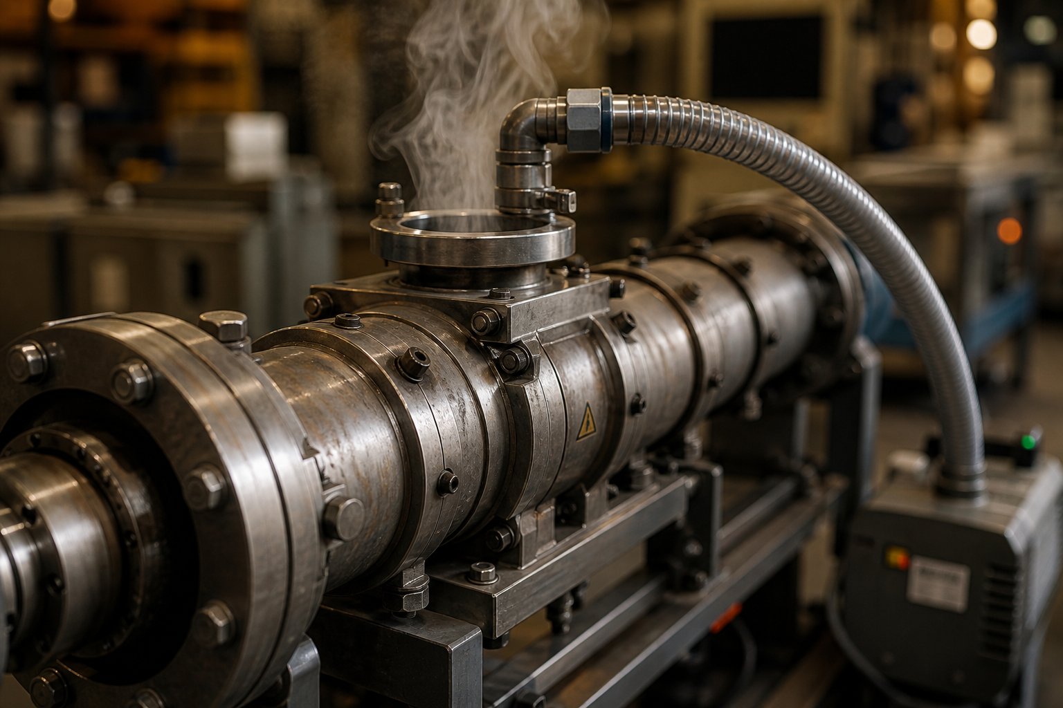
Devolatilization is a mass-transfer process driven by thermodynamics and diffusion. The basic mechanism involves superheating the volatile component within the polymer melt, then exposing that melt to a rapid decompression at a vent port where pressure drops sharply. Volatiles flash out of the melt surface and escape through the open barrel port as vapor.
But here's where placement becomes everything. A vent port only works when it sits directly over a screw zone with low fill level and minimal pressure. Engineers create this condition using upstream melt seals — reverse conveying elements, neutral kneading blocks, or blister rings that force the screw to be completely full at a specific location. This filled section isolates the low-pressure vent zone from upstream high-pressure regions, preventing vacuum from pulling through the extruder barrel and disrupting process stability.
The downstream side needs its own seal, too. If the restriction downstream of the vent is too tight, or the throughput too high relative to screw speed, the filled length of screw backs up under the vent opening — a condition called vent flooding. Molten polymer flows out through the port instead of volatiles escaping through it, blocking the vacuum piping and forcing a line shutdown. Screen fouling and die-hole blockage downstream have the same effect: as discharge pressure rises, the backup length extends until it reaches the vent.
Twin-screw extruder machine operators encounter two distinct venting modes, each suited to different volatile loads:
- Atmospheric venting — Used for removing large volumes of steam, entrained air from side-fed powders, or initial moisture from hygroscopic polymers. These vents are simple open ports where vapor velocity must stay low enough to prevent entraining fine particles. When side-feeding low-bulk-density fillers at high loadings, multiple atmospheric vents may be required to handle the sheer volume of displaced air.
- Vacuum venting — Connected to a vacuum pump operating at 100 to 300 mbar, this mode extracts dissolved volatiles, residual monomers, and trace contaminants that atmospheric pressure alone cannot remove. A practical rule of thumb: each vacuum vent reduces volatile concentration by roughly an order of magnitude. A triple-vented machine, for example, can bring a 50%-solids feed down to below 0.1% residuals.
For specialty materials that foam or expand under vacuum, standard open vents fail entirely — the swelling melt simply fills the port. In these cases, mechanical vent stuffers (small twin-screw devices mounted inside the vent opening) physically push the melt back into the barrel channel while still allowing vapor to escape axially through the stuffer screws. It's an elegant solution to a problem that has no simple setpoint fix.
Screw speed changes deserve special attention here. Increasing rpm shortens the filled length behind both the upstream and downstream melt seals, making them more susceptible to failure. Decreasing rpm lengthens the filled zones — improving seal integrity on the upstream side but increasing the risk of polymer backing up into the downstream vent. Every speed adjustment shifts the pressure profile, and the operator who understands this relationship avoids the trial-and-error frustration of chasing vent flooding across multiple zones.
Gearbox and Drive System Fundamentals
Every screw element, every kneading block, every restrictive seal discussed so far relies on one thing: torque delivered through the shaft. The gearbox is the mechanical heart of the extruder for polymer processing, responsible for reducing motor speed to the required screw rpm while multiplying torque proportionally. A motor spinning at 1,500 rpm must be geared down to perhaps 300-600 rpm at the screws, and the torque increases by the same reduction ratio.
What makes twin-screw gearbox design uniquely challenging is the requirement to split that torque evenly between two closely spaced, intermeshing shafts. Any imbalance causes one screw to lead and the other to lag, introducing timing errors that risk screw-to-screw interference. In co-rotating systems, even a fraction of a degree of angular timing error under load can cause the screws to contact each other — damaging both the screw elements and the gearbox internals. This synchronization requirement adds an entire layer of engineering complexity beyond what single-screw drives ever face.
The metric that matters most when evaluating gearbox capability is torque density, measured in Nm/cm3. This figure relates the gearbox's continuous torque capacity to the screw cross-sectional area it drives. Modern high-performance twin-screw extruder machines achieve torque densities around 18 Nm/cm3 — a 30% improvement over previous generations — enabling the processing of materials like glass-filled polyamide and highly loaded mineral compounds that were previously torque-limited.
Gearbox torque capacity is often the true bottleneck in extruder performance. Maximum torque density directly determines the upper limit of specific energy input — and therefore the range of materials a given machine can process.
Consider the practical implications. Torque equals the motor's ability to do work on the polymer. When an engineer designs a screw profile with aggressive kneading blocks and tight restrictions for dispersing a difficult filler, the gearbox must supply enough continuous torque to drive the screws through that resistance without tripping a safety limit. If the gearbox torque rating falls short, the only options are reducing screw speed (sacrificing mixing intensity), lowering feed rate (cutting throughput), or redesigning the screw profile with less aggressive elements (compromising dispersion quality). Every one of those compromises traces back to the gearbox.
Thrust load absorption adds yet another demand. As melt pressures build against the die, the resulting axial force pushes both screws rearward into the gearbox. Twin-screw extruders can generate back pressure forces ranging from 2.5 kN on small laboratory units to over 3,400 kN on large production machines. The thrust bearing inside the gearbox must absorb this load continuously, and its fatigue life — typically designed for approximately 12,000 hours under normal operating conditions — often becomes the life-limiting factor before the gear train itself shows any wear. Running at 80% of continuous torque rating and 80% of maximum speed provides the operational margin that protects against premature gearbox failure.
These venting and drive system realities shape every downstream decision about what the extruder can actually produce. And the range of what twin screw systems produce extends far beyond polymer compounding — spanning industries from food processing to pharmaceuticals, each demanding its own adaptation of these same working principles.
Industrial Applications and How the Working Principle Adapts
Every screw profile, barrel arrangement, and parameter interaction discussed so far serves a single purpose: transforming raw materials into finished products that meet exact performance specifications. What makes twin screw extrusion so dominant across manufacturing is not just the physics — it's how flexibly those physics adapt when the application changes. The same machine platform that compounds glass-filled nylon at 300 °C can be reconfigured to texturize plant protein at 140 °C or process a pharmaceutical solid dispersion at 120 °C. The working principles remain constant; the configuration shifts entirely.
Here's a snapshot of the major sectors where twin screw extruders deliver value — and how screw and barrel setups are tailored for each one:
- Polymer compounding — Intensive kneading zones for filler dispersion, gentle conveying sections to preserve fiber length, and vacuum venting for moisture and volatile removal.
- Pelletizing and granulation — High-pressure discharge zones feeding strand or underwater pelletizing dies; screw profiles optimized for melt homogeneity and consistent die pressure.
- Pipe, profile, and sheet extrusion — Counter-rotating configurations generating stable melt pressure for dimensional accuracy through calibration tooling.
- Plastic recycling — Robust venting stages for contaminant removal, flexible feed systems for inconsistent input streams, and wear-resistant barrel liners for abrasive post-consumer materials.
- Reactive extrusion — Extended L/D ratios with liquid injection barrels for initiators, precise temperature zoning, and multiple vacuum vents for byproduct removal.
- Food processing — Controlled shear and cooking profiles for starch gelatinization and protein texturization at moderate temperatures.
- Pharmaceutical hot-melt extrusion — Low-shear conveying with tight thermal control for embedding active pharmaceutical ingredients in polymer carriers.
Polymer Compounding and Plastic Processing
Polymer compounding is where the compounding twin screw extruder earns its reputation. The task sounds straightforward — blend a base polymer with fillers, colorants, stabilizers, flame retardants, or reinforcing fibers — but the engineering challenge is immense. Each additive has different particle size, surface energy, density, and thermal sensitivity. A single formulation might require aggressive dispersive mixing for carbon black agglomerates, gentle distributive blending for heat-sensitive stabilizers, and minimal-shear conveying for long glass fibers that lose mechanical performance every time they fracture.
A typical twin screw compounding extruder profile for a 30% glass-fiber-reinforced polyamide illustrates this balance. The upstream section features standard conveying elements and forward kneading blocks that melt the base resin. Glass fibers enter downstream through a side-feed barrel — well past the high-shear melting zone — so they encounter only the conveying and gentle mixing elements needed to wet them with the polymer matrix. If those fibers passed through the primary kneading section, average fiber length would drop from 3-4 mm to under 0.5 mm, and the final product's impact strength would collapse.
Downstream processes define what happens after the melt exits the die. A plastic twin screw extruder feeding a strand pelletizer produces cylindrical pellets for injection molding feedstock. The same machine fitted with an underwater pelletizing system produces spherical micropellets for rotational molding or powder coating applications. In sheet extrusion, a flat die replaces the strand die, and the melt feeds directly into a polishing stack. For pipe and profile lines — especially PVC — counter-rotating conical extruders generate the stable, pulsation-free melt pressure that calibration tooling demands. In every case, the polymer extruder's screw profile is purpose-built for the downstream geometry.
A screw extruder granulator configuration for masterbatch production, for instance, pushes the boundaries of dispersive mixing. Pigment agglomerates must be broken down to primary particle size — often below one micron — requiring aggressive 90° kneading blocks followed by gear mixing elements that distribute the dispersed pigment uniformly through the carrier resin. The compounding extruder in this role functions as a precision dispersion tool, not simply a melting and conveying device.
Recycling and Reactive Extrusion Applications
Recycling pushes every twin screw extruder plastic processing capability to its limit. Post-consumer waste arrives as a chaotic mixture: variable composition, unpredictable moisture content, paper label contaminants, residual food oils, and inconsistent bulk density. Post-industrial regrind is cleaner but still introduces batch-to-batch variation that a virgin-material screw profile would never encounter.
Screw configurations for recycling operations emphasize three priorities. First, aggressive venting — often two or three atmospheric vents plus one or two vacuum stages — handles the massive volatile load from moisture, printing inks, adhesive residues, and low-molecular-weight degradation products. Second, the feed section uses extended-pitch conveying elements paired with a crammer feeder to manage the low bulk density of flake and film feedstock. Third, melt filtration systems downstream of the extruder remove particulate contaminants, but they impose significant back pressure that the screw profile must accommodate without destabilizing the upstream vent seals.
Abrasive fillers and contaminants in recycled streams accelerate wear on both screw elements and barrel liners far faster than virgin compounding ever would. Glass fiber fragments, calcium carbonate residues, and mineral particles erode flight tips and barrel bores, widening clearances that degrade self-wiping performance and reduce mixing efficiency. Maintaining original-specification screw and barrel components becomes a recurring operational requirement — and partnering with suppliers like NANHAIYA, who provide replacement screw barrels engineered for pipe, profile, sheet, pelletizing, and recycling lines, keeps these machines running at peak throughput rather than limping along with degraded geometry.
Reactive extrusion transforms the twin screw plastic extruder from a blending tool into a continuous chemical reactor. Grafting maleic anhydride onto polyolefins, crosslinking silane-modified polyethylene, or performing controlled rheology degradation of polypropylene — each reaction uses the extruder's precise temperature control, residence time distribution, and liquid injection capability to replace batch reactors with continuous processing. Peroxide initiators or reactive monomers are injected through dedicated barrel ports, and the extruder's tightly controlled residence time ensures uniform conversion without the over-reaction risks inherent in batch kettles.
Food and Pharmaceutical Extrusion
Step outside the plastics world, and the same twin screw working principles find entirely different expression. In food processing, co-rotating twin screw extruders cook, texturize, and shape products ranging from breakfast cereals to high-moisture meat analogs. Starch gelatinization requires precise combinations of shear, moisture, and temperature — too much mechanical energy produces a gummy, over-worked texture, while too little leaves raw starch granules intact. Screw profiles for food extrusion typically use fewer kneading blocks and rely more on conveying elements with controlled restriction points to manage shear gently.
Plant-based protein texturization represents one of the fastest-growing food extrusion applications. Here, the extruder creates a fibrous, meat-like structure by aligning protein molecules under controlled shear and cooling conditions in a long cooling die. Barrel temperatures, moisture injection rates, and screw speed interact exactly as they do in polymer processing — but the target is texture rather than molecular dispersion.
Pharmaceutical hot-melt extrusion (HME) adapts the same platform for an entirely different purpose: embedding poorly soluble active pharmaceutical ingredients into polymer carriers to enhance bioavailability. Processing temperatures are typically moderate (100-160 °C), and screw profiles prioritize distributive mixing over high-shear dispersion. The critical requirement is an extremely narrow residence time distribution — every particle of API must experience the same thermal history to guarantee uniform drug release kinetics. Self-wiping co-rotating geometry delivers exactly that consistency, which is why twin screw extrusion has become the standard platform for continuous pharmaceutical manufacturing under FDA and EMA guidelines.
Across every one of these sectors, the underlying physics remain identical: drag flow moves material forward, kneading blocks input mechanical energy, vent ports remove volatiles, and the gearbox delivers the torque that makes it all possible. What changes is the configuration — and configuring the right machine for a specific application brings the conversation full circle to scale-up principles and equipment selection.
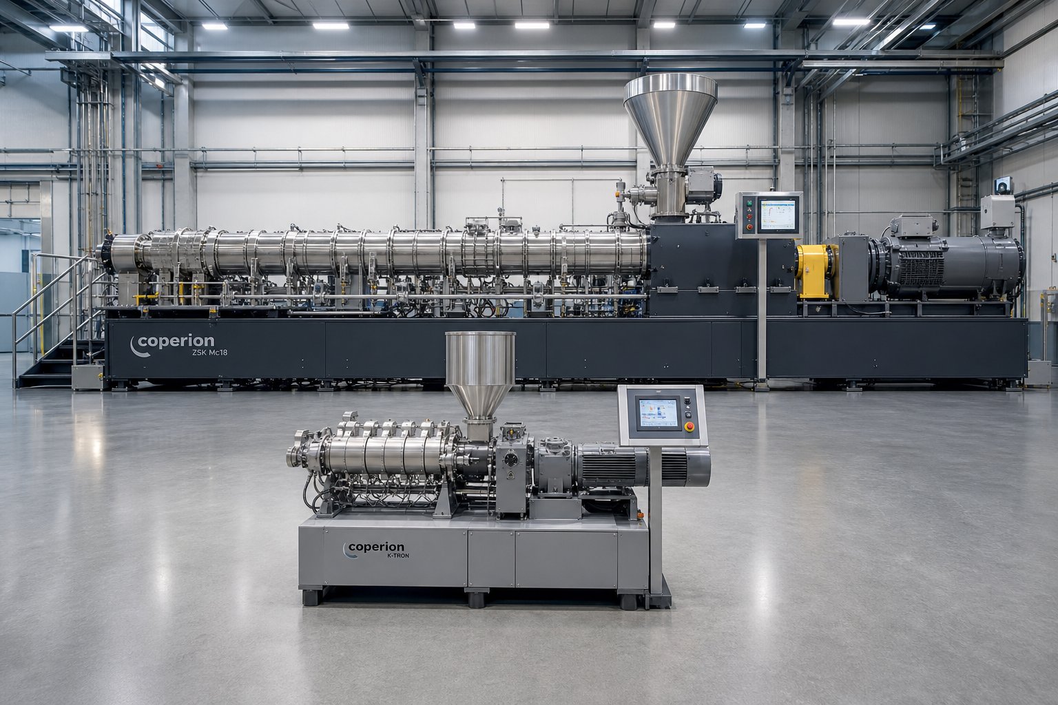
Scaling Up and Selecting the Right Twin Screw Extruder Configuration
Every formulation starts small. A laboratory twin screw extruder with a 15 mm or 20 mm screw diameter processes a few hundred grams per hour — just enough to validate a concept, screen additives, or confirm reaction kinetics. The real challenge arrives when that formulation must run at 500, 1,000, or 2,000 kg/h on a production-scale double screw extruder machine. Scale-up is where theoretical understanding of twin screw extruder working meets engineering reality, and where small oversights become expensive mistakes.
Scale-Up from Laboratory to Production Extruders
The fundamental premise of scale-up is geometric similarity: the production extruder should be a proportionally enlarged version of the lab machine. Both machines share the same L/D ratio, the same screw element sequence (expressed in diameters rather than millimeters), and the same barrel section arrangement. A benchtop twin screw extruder running at 40:1 L/D scales to a 92 mm production machine also configured at 40:1 L/D, preserving the relative zone lengths for feeding, melting, mixing, venting, and pressure build-up.
Sounds straightforward? It isn't. Technovel's scale-up analysis identifies a core tension between two competing scaling laws. The cubic law scales throughput proportionally to D3 — the cube of the screw diameter — treating the extruder as a volumetric processing device. Under this approach, scaling from a 15 mm to a 60 mm screw (a 4x diameter ratio) theoretically increases throughput by a factor of 64. Productivity soars, but peripheral speed rises with diameter, shear heating intensifies, and the melt temperature history diverges from the lab baseline.
The square law scales throughput proportionally to D2, treating the extruder as a heat-transfer-limited system. The same 4x diameter increase yields only a 16x throughput gain — more conservative, but far better at preserving the thermal history and mixing state that produced good results on the small machine. The geometric reason is simple: internal volume grows with D3, but barrel surface area — the primary pathway for heating and cooling — grows only with D2. Larger machines have proportionally less surface area to manage heat, making temperature history reproduction inherently more difficult at production scale.
Real-world scale-up sits between these two extremes. The engineer's task is finding the point where throughput is maximized without sacrificing the product quality established during development. Here are the key scale-up parameters, listed in the order most experienced teams prioritize them:
- Specific mechanical energy (SME) — Match the kWh/kg value from the lab machine to the production machine. SME captures the actual mechanical work done on the polymer and is the single most reliable indicator of mixing and melting equivalence across scales.
- Geometric similarity (constant L/D) — Maintain identical L/D ratios and screw element sequences expressed in diameter multiples to preserve relative zone lengths and residence time distribution shape.
- Residence time distribution (RTD) — Verify that the mean residence time and distribution width on the production machine approximate the lab results. Wider RTD at larger scale typically indicates dead zones or overfilling that the screw profile must address.
- Melt temperature profile — Monitor actual melt temperature rather than barrel setpoints. Expect viscous dissipation to play a larger role at production scale due to the reduced surface-area-to-volume ratio.
- Fill ratio (Q/N ratio) — Maintain a comparable ratio of throughput to screw speed to preserve the fill state and pressure profile within the screw channels.
- Torque utilization — Confirm that the production gearbox has sufficient torque density to drive the same screw configuration without operating above 80% of continuous rating.
One practical reality deserves emphasis. Twin screw extruder manufacturers offer machines ranging from micro-scale research units (as small as 6 mm diameter) through pilot-scale systems (26-35 mm) to full production platforms (40-135 mm and above). Each step up in diameter amplifies the surface-area-to-volume challenge. A process that ran beautifully on a 26 mm pilot machine with excellent barrel temperature control may overheat on a 70 mm production unit because the barrel simply cannot extract heat fast enough to compensate for the increased viscous dissipation. Adjusting screw speed downward, modifying the kneading block sequence, or adding cooling-optimized barrel sections are all legitimate responses — but only if the engineer understands why the temperature shifted in the first place.
When reproducibility of material quality is the absolute priority and scale-up introduces unacceptable risk, an alternative strategy exists: running multiple smaller extruders in parallel rather than consolidating onto one large machine. This approach preserves the shear history, residence time, and temperature profile almost identically. The trade-off is higher capital cost, larger floor space, and greater operational complexity — factors that push most operations toward the single-machine scale-up path despite its technical demands.
Choosing the Right Screw and Barrel Configuration for Your Process
Every working principle explored throughout this article — transport physics, modular screw elements, barrel section types, parameter interactions, venting strategies, and gearbox limitations — converges in a single practical decision: how do you configure a specific extruder for a specific application?
There is no universal screw profile. A configuration optimized for dispersing carbon black in polyethylene would destroy glass fibers in a reinforced polyamide compound. A venting arrangement designed for post-consumer recycling would be entirely unnecessary for a dry, pre-compounded masterbatch. The configuration must match the process, and matching the process requires understanding the physics deeply enough to anticipate how each element and barrel section will behave with the specific materials at hand.
Here's a practical framework for approaching configuration decisions:
- Define the process objective first — Is the primary challenge melting, dispersive mixing, distributive blending, devolatilization, or pressure generation? Each objective demands a different balance of kneading blocks, conveying elements, and restriction elements.
- Map the barrel layout to match — Position feed ports, side-feed barrels, atmospheric vents, and vacuum vents so that each one aligns with the correct screw zone. A vent must sit over a low-pressure, partially filled screw section — never over a fully filled mixing zone.
- Select screw elements zone by zone — Start with wide-pitch conveying at the feed, transition through kneading blocks for melting and mixing, place restriction elements where melt seals are needed, and finish with metering elements that build stable die pressure.
- Account for wear and replacement — Abrasive formulations erode flight tips and barrel bores, widening clearances that degrade self-wiping action and mixing quality over time. Planning for periodic replacement of screw elements and barrel liners is not optional — it's part of the process design.
That final point connects directly to supplier selection. Working with specialized screw barrel providers like NANHAIYA ensures that technical teams sourcing replacement or custom screw barrels for their plastic extruder machines receive components engineered to match specific processing requirements — whether the application is pelletizing, recycling, pipe, profile, or sheet production. Precision-manufactured replacement components restore original clearances and self-wiping geometry, recovering the mixing performance and throughput capacity that wear gradually erodes.
The twin screw extruders market continues to expand as extruder technology finds new applications in recycling, battery materials, bioplastics, and pharmaceutical manufacturing. Each new application brings fresh configuration challenges — and each challenge reinforces the same lesson: understanding the underlying physics is not academic luxury. It's operational necessity.
Understanding twin screw extruder working principles empowers engineers to design better screw configurations, troubleshoot process issues faster, and maximize equipment performance across every application and every scale.
Whether you're running a benchtop twin screw extruder to develop a new formulation or managing a fleet of production-scale machines from multiple twin-screw extruder manufacturer sources, the physics never change. Drag flow, pressure flow, and leakage flow still compete in every channel. Kneading blocks still convert mechanical energy into mixing work. Vent ports still require properly placed melt seals. And the gearbox still sets the upper boundary of what the machine can do. Master those fundamentals, and every configuration decision — from element selection to scale-up strategy — becomes a logical extension of what you already understand.
Frequently Asked Questions About Twin Screw Extruder Working
1. What is the basic working principle of a twin screw extruder?
A twin screw extruder operates by rotating two intermeshing screws inside a figure-eight-shaped barrel bore. The screws convey raw material forward while subjecting it to controlled shear forces and thermal energy, melting, mixing, and homogenizing the material into a uniform output. Co-rotating designs transfer material between screws in a figure-eight flow path for superior mixing, while counter-rotating designs create sealed C-shaped chambers for high-pressure pumping. Modular screw elements — conveying flights, kneading blocks, and mixing discs — slide onto splined shafts, letting engineers customize the screw profile for each specific formulation and process requirement.
2. What is the difference between co-rotating and counter-rotating twin screw extruders?
Co-rotating twin screw extruders spin both screws in the same direction, creating an open intermesh zone where material transfers between screws and undergoes elongational mixing. This makes them ideal for compounding, reactive extrusion, and devolatilization. Counter-rotating extruders rotate screws in opposite directions, forming enclosed C-shaped chambers that act as positive-displacement pumps with minimal backflow. They generate higher and more consistent die pressure, which is why they dominate PVC pipe and profile extrusion. The choice depends on whether your process is mixing-limited (co-rotating) or pressure-limited (counter-rotating).
3. How do kneading block stagger angles affect mixing in a twin screw extruder?
Kneading blocks consist of disc-shaped lobes stacked at specific stagger angles that determine mixing intensity and conveying behavior. A 30-degree forward stagger provides gentle distributive mixing with strong forward conveying, suitable for heat-sensitive polymers. A 60-degree stagger balances dispersive and distributive mixing with moderate conveying, commonly used in primary melting zones. A 90-degree neutral stagger delivers maximum dispersive mixing with zero forward conveying, acting as a melt restriction for pigment dispersion or complete melting. Reverse-staggered blocks pump material backward for the most aggressive shear input, extending residence time in critical zones.
4. Why is starve feeding preferred over flood feeding in co-rotating twin screw extruders?
Starve feeding uses a gravimetric feeder to meter material at a rate below the screw's maximum conveying capacity, keeping the feed-zone channels only partially filled. This decouples throughput from screw speed — engineers can increase rpm for more mixing intensity without raising production rate, or boost feed rate without changing the shear profile. Flood feeding, used in single-screw and some counter-rotating systems, fills the screw completely and tightly couples output to screw speed, limiting independent optimization. Starve feeding also reduces pressure fluctuations at the die, improving dimensional consistency and weight control of the final product.
5. How do you scale up a twin screw extrusion process from lab to production?
Successful scale-up maintains geometric similarity by preserving the L/D ratio and screw element sequence expressed in diameter multiples. The most reliable indicator is matching specific mechanical energy (SME in kWh/kg) between the lab and production machines. Engineers must also account for the reduced surface-area-to-volume ratio at larger diameters, which limits barrel cooling capacity and intensifies viscous dissipation. Monitoring actual melt temperature rather than barrel setpoints, maintaining comparable Q/N (throughput-to-speed) ratios, and confirming adequate gearbox torque density are all critical steps. Working with experienced screw barrel suppliers like NANHAIYA (nhyscrews.com) ensures replacement and custom components match the precise processing requirements across pelletizing, recycling, pipe, profile, and sheet applications.
Written by
Nanhaiya Technical Team
Zhoushan Nanhaiya Plastic Machinery Co., Ltd.
The Nanhaiya technical team supports screw and barrel manufacturing projects through application review, technical communication, custom manufacturing coordination, and production and quality control.
Discuss Your Application
Related Articles
More insights on screw barrel technology and plastics processing.

Extruder Machine Decoded: From Raw Pellet To Finished Product
Oct 6, 2026
Learn how an extruder machine works, compare single-screw vs. twin-screw types, and get expert guidance on specs, troubleshooting, and selection.
Read Article
PE Pipe Making Machine Decoded: From Raw Resin to Flawless Pipe
Oct 4, 2026
Learn how a PE pipe making machine works, from resin to finished pipe. Covers components, material grades, automation, troubleshooting, and buyer selection tips.
Read Article
PVC Profile Making Machine Decoded: From Raw Resin To Profit
Oct 3, 2026
Learn how a PVC profile making machine works — extrusion process steps, key technical parameters, die design, calibration methods, maintenance, and total cost of ownership.
Read ArticleLooking for something else?
Search by material, symptom or product and jump straight to the relevant page.
These are navigation suggestions based on keyword matching — not a quotation, not a delivery commitment, and not a substitute for engineering review. Final specification is confirmed by our engineers against your drawings and processed material.
Need help with screw barrel selection?
Share your machine model, processed material and application. Our team can help with pricing and technical support.