

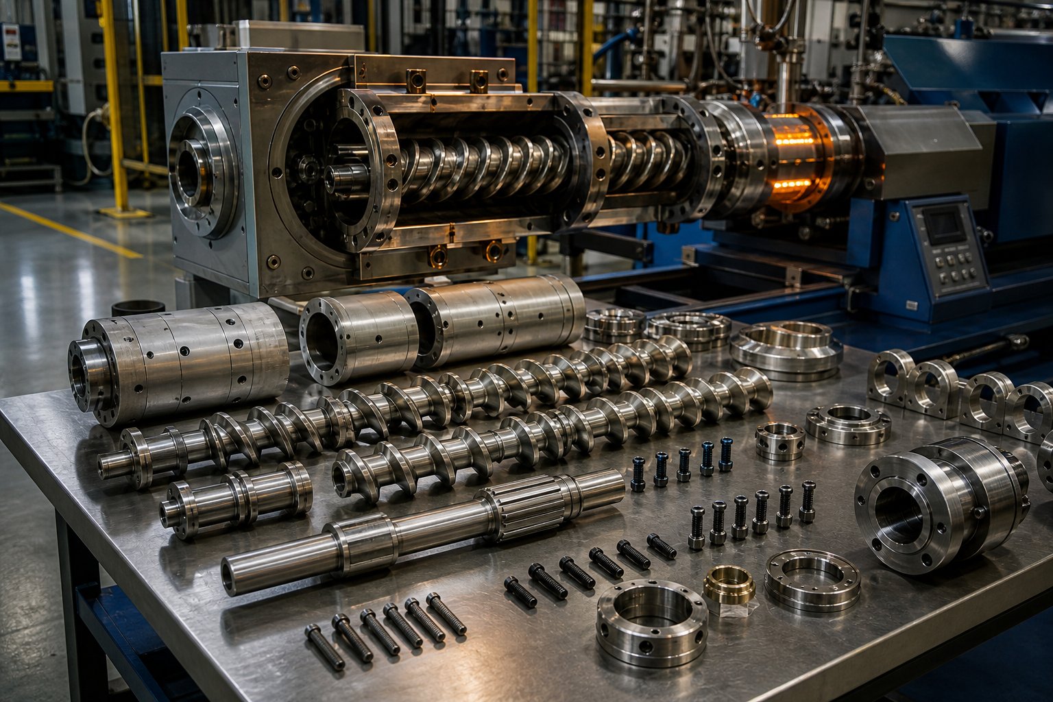
Understanding Twin Screw Extruder Spare Parts and Why They Matter
Imagine your twin screw extruder grinding to a halt mid-production because a single worn screw element finally gave out. The downtime clock starts ticking, your team scrambles for a replacement, and nobody on the floor is entirely sure which specification to order. Sound familiar? That scenario plays out in compounding plants, recycling facilities, and pharmaceutical production lines more often than it should - and it almost always traces back to a gap in spare part knowledge.
What Are Twin Screw Extruder Spare Parts
Twin screw extruder spare parts encompass every replaceable component within the extruder system that maintains, restores, or optimizes processing performance. The term covers a broad ecosystem of parts, and understanding its full scope is the first step toward smarter procurement.
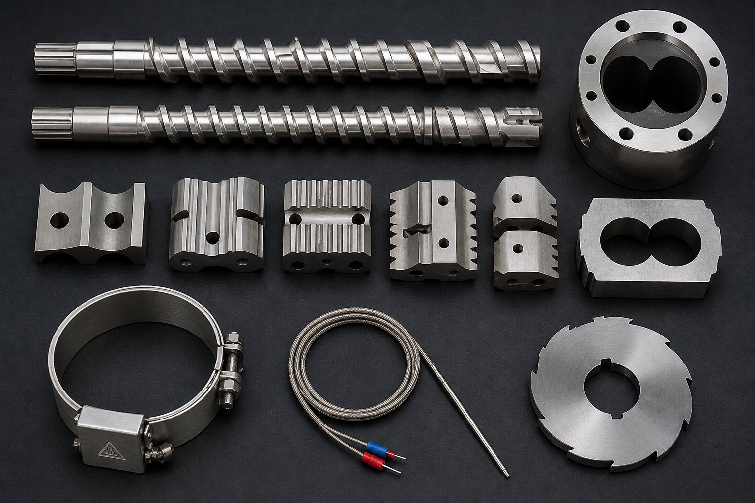
Twin screw extruder spare parts are the complete range of replacement components - including screw elements, barrels, screw shafts, heater bands, thermocouples, die heads, pelletizing blades, gearbox internals, seals, and coupling assemblies - required to maintain continuous extrusion performance across plastics compounding, food processing, pharmaceutical, and chemical applications.
At the heart of any twin screw extruder, you'll find the extruder screws and barrels. These are the primary wear components, handling intense mechanical stress, abrasive fillers, and chemically aggressive melts on every rotation. The extruder screw barrel assembly - the paired unit of intermeshing screws seated inside precision-bored barrel segments - is where raw material transforms into a homogenized product. Beyond this core twin screw and barrel pairing, the system relies on dozens of auxiliary components: heating elements that regulate melt temperature zone by zone, thermocouples providing real-time thermal feedback, die assemblies that shape the final extrudate, and pelletizing blades that cut it into uniform granules. Even gearbox gears, bearings, and shaft seals play essential roles in keeping the drive train synchronized and leak-free.
Why Spare Part Knowledge Matters for Plant Operations
Here is the reality most equipment catalogs won't tell you: ordering the right part is only half the challenge. Understanding why that part wears, what material grade it should be made from, and how its dimensional tolerances affect your end product - that knowledge is what separates reactive maintenance teams from proactive ones.
When maintenance professionals understand part functions and wear patterns, the benefits are tangible. Unplanned downtime drops because replacements are stocked before failures occur. Costs stay controlled because teams select the right material for the actual wear environment rather than defaulting to the most expensive option. Processing quality holds steady because worn components get swapped before clearances drift out of specification. Industry data underscores the stakes: the service life of ordinary nitrided steel screws and barrels can range from just 3 to 12 months depending on the materials being processed, which means replacement decisions come around frequently.
This article walks through every critical dimension of that decision-making process. You'll find a complete breakdown of spare part categories and their functions, a technical explanation of shaft and spline configurations, the differences between co-rotating and counter-rotating part geometries, a deep look at wear mechanisms and the materials engineered to combat them, barrel segment types and their process roles, precision and quality assurance benchmarks, practical methods for identifying when parts need replacement, and a clear framework for evaluating aftermarket suppliers. Each section targets a specific knowledge gap that no product listing alone can fill - giving your team the information needed to choose replacement components with confidence rather than costly guesswork.
Complete Breakdown of Spare Part Categories and Their Functions
Every twin screw extruder spare part exists for a reason - and when you understand what each component actually does in the process, ordering replacements stops being a guessing game. Most supplier catalogs list part numbers and photos without context, leaving buyers to figure out the "why" on their own. This section fills that gap by walking through every major category, explaining its function, and showing how the pieces work together as a system.
Screw Elements and Feed Screws
The extruder screw profile is not a single machined piece. In a modular twin screw system, individual screw elements are assembled onto a shaft, and each type of element serves a distinct processing purpose. Think of it like building a recipe - the arrangement determines the outcome.
Conveying elements are the workhorses. Their deep helical flights move material forward through the barrel efficiently, with minimal shear input. As NC State Extension research explains, deeper channel screws provide better material conveyance with higher screw volume, making these elements essential in the feed and transport zones of the extruder.
Kneading blocks handle the heavy lifting when it comes to mixing. Wider kneading elements promote dispersive mixing - breaking down agglomerates by applying strong shear stress - while narrower discs contribute to distributive mixing, spreading the dispersed phase evenly without particle breakdown. The stagger angle between discs (commonly 30, 45, 60, or 90 degrees) and the direction of offset (forward, neutral, or reverse) determine how aggressively each block works. Forward kneading blocks are less aggressive, neutral blocks increase residence time by providing no conveying action, and reverse kneading blocks push material backward to create maximum restriction and shear.
Mixing elements, such as toothed or gear-type designs, provide distributive mixing with minimal shear - ideal for blending temperature-sensitive additives without degrading them. Reverse elements (left-handed conveying elements) create intentional flow restriction, building pressure and extending residence time upstream. They are essential for creating melt seals before venting zones.
The feed screw sits at the very beginning of the process, typically housed in or near a double screw feeder or gravimetric feeding system. Its job is to accept incoming raw material from the hopper and drive it consistently into the first barrel section. Feed screws are designed with aggressive pitch and open channel geometry to handle bulk solids - including powders, pellets, and flakes - without bridging or starving the extruder.
Barrels and Feed Barrels
Barrel segments line up end-to-end to form the housing that contains and channels material under extreme heat and pressure. Each segment bolts to its neighbor, creating a sealed process cavity around the rotating screws. The precision of the barrel bore directly affects processing performance - the running clearance between screw flights and barrel wall is remarkably tight, often well under a tenth of a millimeter on a standard machine, as noted in industry engineering guides.
The extruder feed barrel deserves special attention because it handles conditions unlike any other segment. Positioned at the material intake, it operates at lower temperatures and faces the unique challenge of pulling in solid granules or powder without melting them prematurely. Many feed barrels feature internal cooling channels and grooved bore surfaces to improve solids conveying. Because they experience constant abrasion from hard, unmelted feedstock, feed barrel sections often wear differently than downstream segments and may need replacement on a separate schedule.
Standard barrel segments downstream serve as heated containment zones, with external heater bands and internal cooling circuits providing zone-by-zone temperature control. Specialty barrels - vented, side-feed, or closed configurations - add further functionality, which later sections of this article explore in detail.
Auxiliary Components and Wear Parts
Beyond the core screw and barrel system, a twin screw extruder relies on a network of auxiliary parts that directly impact process stability and product quality. Heater bands (ceramic or mica) wrap around barrel segments and die heads to deliver precise thermal energy zone by zone. Thermocouples inserted into the barrel wall or melt stream provide the temperature feedback that your control system depends on - a failed thermocouple means blind-spot heating.
Die heads shape the molten polymer as it exits the extruder. In compounding applications, strand die heads with multiple holes are common, while underwater pelletizing die heads are preferred for heat-sensitive materials. As Kerke Extruder's technical guide notes, die heads must handle pressures of 200-300 bar and temperatures up to 350 degrees Celsius while maintaining dimensional accuracy. Pelletizing blades work in concert with the die face, and their sharpness and material hardness directly determine pellet uniformity and cut quality.
Gearbox components - including gears, bearings, and oil seals - transmit torque from the motor to the screw shafts. Coupling assemblies connect the gearbox output to the screws, absorbing misalignment and vibration. Even feeder screws in upstream dosing equipment, whether volumetric or gravimetric systems using a double screw feeder configuration, qualify as critical replacement items since inconsistent feeding immediately undermines process stability downstream.
| Part Category | Primary Function | Typical Materials | Critical Specifications |
|---|---|---|---|
| Conveying Elements | Forward material transport with minimal shear | Nitrided steel, tool steel, powder metallurgy alloys | Pitch, length, flight depth, rotation direction (L/R) |
| Kneading Blocks | Dispersive and distributive mixing | Tool steel, PM alloys, tungsten carbide coated | Disc count, stagger angle, disc width, offset direction |
| Feed Screw | Material intake from hopper into barrel | Nitrided steel, case-hardened alloy steel | Pitch, OD, shaft bore type, flight geometry |
| Barrel Segments (Standard) | Contain and channel material under heat/pressure | Nitrided alloy steel, bimetallic lined steel | Bore diameter, length, center distance, cooling channel layout |
| Extruder Feed Barrel | Solids intake with cooling and anti-bridging features | Nitrided steel with cooling jackets | Bore profile (smooth/grooved), cooling capacity, throat geometry |
| Heater Bands | Deliver thermal energy to barrel zones and die | Ceramic fiber, mica, stainless steel sheath | Wattage, voltage, ID, width, band type (ceramic/mica) |
| Thermocouples | Temperature measurement and feedback to PLC | Type J or K thermocouple wire, stainless steel sheath | Probe length, diameter, connection type, response time |
| Die Heads | Shape molten polymer into strands, pellets, or profiles | H13 tool steel, tungsten carbide inserts, stainless steel | Hole count, hole diameter, land length, pressure rating |
| Pelletizing Blades | Cut extrudate into uniform pellets | High-speed steel, carbide-tipped steel | Blade count, edge geometry, mounting pattern, hardness |
| Gearbox Components | Torque transmission from motor to screw shafts | Case-hardened alloy steel, bronze bearings | Gear ratio, torque rating, bearing dimensions, oil seal sizes |
| Coupling Assemblies | Connect gearbox output to screw shafts | Alloy steel, elastomeric elements | Torque capacity, shaft bore size, spline type, misalignment tolerance |
The breadth of this component ecosystem highlights a practical sourcing challenge: finding a single supplier who covers everything from screw elements and barrels to heater bands, die heads, and custom-machined parts. For teams that prefer consolidated procurement, NANHAIYA's extruder spare parts catalog provides one example of a supplier offering the full range - including custom manufacturing from drawings or samples - which simplifies ordering and reduces the risk of specification mismatches across vendors.
Each of these component categories interacts with the others. A new set of kneading blocks won't deliver optimal dispersion if the barrel bore has worn past tolerance, and a perfectly machined die head underperforms when upstream heater bands fail to hold temperature. That interdependence is exactly why understanding shaft systems - the backbone connecting screws to the drive train - matters just as much as knowing the elements themselves.
Screw Shaft Types and Spline Configurations Explained
The screw shaft is the component that ties everything together - literally. Without it, those carefully selected conveying elements, kneading blocks, and mixing elements would just be loose metal sitting on a workbench. The screw shaft transmits rotational torque from the gearbox through every element stacked along its length, and the way it connects to those elements determines how reliably the entire system performs under load. Yet shaft design is one of the most overlooked topics when buyers source twin screw extruder spare parts.
Spline Shaft Designs in Twin Screw Extruders
Spline shafts use a series of ridges (teeth) machined along the shaft surface that mesh with corresponding grooves inside each screw element's bore. This toothed interface distributes torque uniformly around the shaft circumference - far more evenly than a simple keyway connection ever could. Two primary spline profiles dominate the twin screw extruder world: involute splines and straight-sided splines.
An involute spline shaft features teeth with a curved involute profile, similar in geometry to gear teeth. This design offers a significant advantage: the tooth flanks make contact along a gradually curved surface, which distributes stress more uniformly and reduces localized pressure points. As documented in the ISO 4156 design standard, involute splines are suitable for transferring high, cyclical, and shock torsional moments - exactly the loading conditions inside a twin screw extruder operating at hundreds of RPM with fluctuating material resistance. The involute profile also self-centers the screw element on the shaft, improving concentricity and reducing vibration. Nominal pressure angles of 30 degrees, 37.5 degrees, or 45 degrees are specified depending on the load requirements, and the tooth count is calculated from the pitch circle diameter and module (z = D / m).
Straight-sided splines, by contrast, have rectangular teeth with flat parallel flanks. They are simpler to manufacture and inspect, which made them the standard on older extruder platforms. The trade-off? Load concentration at the tooth corners is higher, and the shaft's ability to handle cyclical shock loads is somewhat reduced compared to an involute spline of similar size. You'll still encounter straight-sided designs on legacy machines and certain smaller-diameter extruders where the torque demands are moderate.
Here is where standards matter for interchangeability. DIN 5480 is the German standard widely adopted by European extruder manufacturers, defining involute spline dimensions by module and tooth count. ISO spline shafts conforming to ISO 4156 provide a broader international framework covering geometry, tolerances, and inspection methods across three pressure angle options. Metric spline standards - sometimes based on regional or manufacturer-specific conventions - may differ subtly in root fillet radius, tooth height, or tolerance class. The practical impact? A screw element manufactured to DIN 5480 specifications may not seat correctly on a shaft machined to a different regional involute standard, even if the nominal diameter appears identical. Always verify the exact spline standard - not just the shaft diameter - before ordering replacements.
Hex Shafts and Alternative Drive Configurations
Not every twin screw extruder uses spline shafts. Some models, particularly certain lab-scale and mid-range machines, use a hexagonal shaft design instead. Imagine a standard hex wrench - the six-sided cross-section transmits torque through flat-to-flat contact between the shaft and a matching hex bore inside each screw element.
A hex shaft offers straightforward manufacturing and easy element assembly. Sliding screw elements on and off is quick because the six-sided geometry provides clear rotational alignment without needing to carefully index teeth. The torque capacity, however, is inherently limited compared to multi-tooth spline shafts. With only six contact faces versus the 20, 30, or more teeth on an involute spline, the hexagonal shaft concentrates stress on fewer, broader surfaces. This makes hex configurations well suited for laboratory extruders and applications with moderate torque requirements, but less practical for large production machines running high-viscosity compounds or heavily filled formulations.
The table below compares the primary screw shaft types you'll encounter when sourcing replacement shafts or screw elements:
| Shaft Type | Torque Capacity | Common Standards | Interchangeability Notes | Typical Applications |
|---|---|---|---|---|
| Involute Spline | High - excellent load distribution across many teeth; handles cyclical and shock loads | ISO 4156, DIN 5480 | Elements must match exact module, tooth count, pressure angle, and tolerance class; DIN and ISO spline shafts may differ in root geometry despite similar nominal dimensions | Production-scale co-rotating and counter-rotating extruders; high-torque compounding |
| Straight-Sided Spline | Moderate to high - higher stress concentration at tooth corners limits peak shock loads | DIN 5462, DIN 5463, ISO 14 | Simpler profile improves cross-manufacturer compatibility in some cases, but tooth count and dimensions must still match exactly | Legacy extruder models; moderate-torque applications; some counter-rotating designs |
| Metric Spline (Manufacturer-Specific) | Varies - depends on tooth count and profile design | Manufacturer-specific or regional metric conventions | Often proprietary; replacement elements typically must come from the original manufacturer or be reverse-engineered from samples | Regional extruder brands; specialized process equipment |
| Hex Shaft | Lower - only six contact faces limit torque distribution | No universal standard; defined by manufacturer specifications (across-flats dimension) | Simpler geometry allows broader element compatibility within a manufacturer's product line, but not across different brands | Laboratory extruders; pilot-scale units; moderate-torque production machines |
Why does all of this matter for your spare parts decisions? Because the screw shaft dictates screw element seating, rotational alignment, and torque transfer along the entire process length. A shaft with worn spline teeth allows elements to develop radial play, which cascades into uneven barrel wear, increased vibration, and inconsistent melt quality. Similarly, ordering elements with the wrong spline bore - say, DIN 5480 elements for a shaft machined to a manufacturer-specific metric profile - means they simply won't fit, or worse, they'll fit loosely enough to run for a few hours before damaging both shaft and element.
The critical takeaway: always document your shaft's exact spline type, tooth count, module, pressure angle, and the governing standard before sourcing any screw elements or replacement shafts. That specification set is just as important as the screw element geometry itself - and it leads directly into the next consideration: how the extruder's rotation direction further defines which parts will and won't work in your machine.
Co-Rotating vs Counter-Rotating Spare Part Differences
Here is a mistake that costs plants thousands of dollars and weeks of lost production: ordering screw elements or barrel segments based solely on shaft diameter and machine brand - without confirming whether the extruder is co-rotating or counter-rotating. The two configurations look similar from the outside, but internally, the geometry of every core component diverges significantly. Getting this wrong means parts that physically cannot run in your machine, or worse, parts that appear to fit but cause rapid wear and process failure within days.
How Co-Rotating Designs Affect Spare Part Geometry
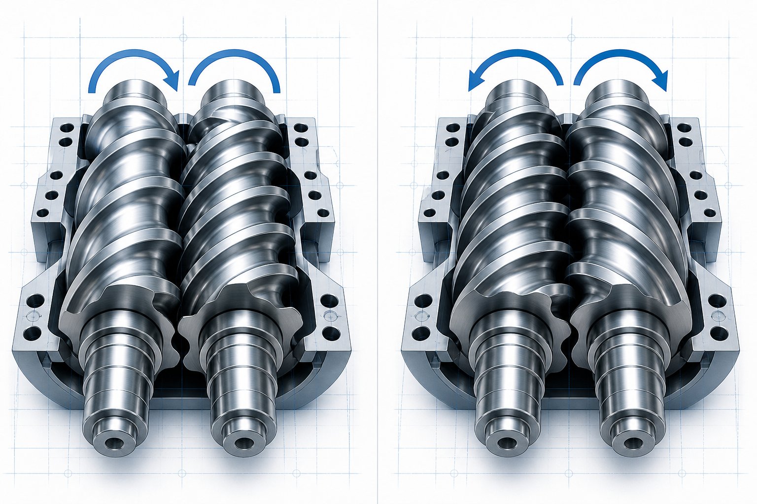
In a co-rotating twin screw extruder, both screws rotate in the same direction - either both clockwise or both counterclockwise. This seemingly simple distinction drives an entirely different element geometry. Co-rotating machines use fully intermeshing, self-wiping screw elements based on what engineers call Erdmenger profiles. The cross-sectional shape of each element is designed so that one screw's flight tip continuously sweeps the root of its partner, preventing material stagnation and creating the characteristic self-wiping action.
Most co-rotating extruders use bi-lobal (two-lobed) element profiles, though some high-performance designs adopt tri-lobal configurations for specific mixing applications. Each lobe profile dictates the ratio between the screw's outer diameter (OD) and inner diameter (ID) - the so-called OD/ID ratio - which in turn determines channel depth, free volume, and the tip clearance between the screw flight and the barrel wall. As Technovel's technical analysis explains, the fully intermeshing geometry produces a flow field where material is forcibly handed off from one screw to the next at the intermeshing region, creating very few dead zones and a narrow residence time distribution.
What does this mean for spare parts? Every screw element - conveying, kneading, or mixing - must match that specific lobe profile precisely. The twin screw barrel bore geometry follows suit: two overlapping cylindrical bores are machined with a precise center-to-center distance that corresponds exactly to the screw element's intermeshing envelope. Even a fraction of a millimeter deviation in bore center distance or element OD compromises the self-wiping clearance, which typically runs extremely tight to maintain mixing efficiency and prevent material degradation from stagnation.
Counter-Rotating Configuration and Its Unique Part Requirements
Counter-rotating extruders flip the script. One screw turns clockwise while the other turns counterclockwise, and this opposite rotation fundamentally changes how material moves through the machine. Instead of the hand-off flow pattern seen in co-rotating designs, counter-rotating screws draw material inward at the intermeshing region, compressing it between the two screws in what engineers describe as a calendering effect - similar to material passing between two rollers.
This calendering action means counter-rotating screw elements have different flight geometries, different intermeshing clearances, and different lobe relationships than their co-rotating counterparts. The screw barrel in a counter-rotating system is designed for the distinct stress distribution and material flow path that opposite rotation creates. Counter-rotating machines, particularly those used for PVC pipe and profile extrusion, often operate at higher fill levels and lower screw speeds, producing lower shear stress - a deliberate design choice for thermally sensitive materials that Bausano's engineering team highlights as critical for avoiding degradation in rigid PVC formulations.
The barrel and screw clearance specifications reflect these differences. Counter-rotating designs may use conical or parallel screw geometries depending on the application, and conical configurations introduce yet another layer of dimensional specificity - tapered barrel bores that have no physical compatibility with parallel-bore parts from a co-rotating machine.
The bottom line? Parts are not interchangeable between co-rotating and counter-rotating configurations. Ordering a set of bi-lobal co-rotating kneading blocks for a counter-rotating extruder - or vice versa - results in elements that either won't physically mount or will destroy themselves and the barrel within hours of operation. Before placing any order for replacement screw elements or twin screw barrel segments, verify the following specifications against your machine's documentation:
- Rotation direction - Confirm whether the extruder is co-rotating or counter-rotating; this is the single most fundamental specification and dictates all downstream geometry.
- Lobe count - Bi-lobal and tri-lobal profiles are not interchangeable, and each produces different OD/ID ratios and channel depths.
- Element flight geometry - Flight pitch, helix angle, and cross-sectional profile differ between configurations; forward and reverse elements are handed specifically to the rotation direction.
- Bore center distance - The distance between the two barrel bore centerlines must match the screw element's intermeshing envelope exactly; co-rotating and counter-rotating machines of the same nominal screw diameter may use different center distances.
- Shaft spline type - As covered in the previous section, the spline standard (DIN, ISO, metric, or hex) must match perfectly - and some manufacturers use different shaft configurations for their co-rotating versus counter-rotating product lines.
Misidentifying any one of these parameters sends you down the wrong sourcing path entirely. The safest practice is to pull the original equipment documentation, record the full model and serial number, and cross-reference every dimensional spec before contacting your supplier. When documentation is unavailable, sending a sample of the worn part to the manufacturer for reverse engineering is far more reliable than estimating from visual inspection alone.
Configuration differences shape which parts you can order - but they also influence how fast those parts wear. The distinct shear profiles, operating speeds, and material types associated with each configuration expose screws and barrels to very different wear mechanisms, and understanding those mechanisms is the key to selecting the right material grade for your replacement components.
Wear Mechanisms and How Spare Part Materials Address Them
Why do some plants burn through screw elements every few months while others run the same set for years? The answer rarely comes down to luck. It comes down to whether the material grade of each replacement part was chosen to resist the specific type of wear that the process actually inflicts. Most suppliers ship parts in a single standard metallurgy and call it a day. But wear is not a single phenomenon - it arrives in at least three distinct forms, each demanding a different defensive strategy.
Abrasive, Adhesive, and Corrosive Wear in Extruder Components
Abrasive wear is the most common culprit in compounding operations. Every time a glass fiber, mineral filler, or calcium carbonate particle is dragged between the screw flight and barrel wall, it acts like microscopic sandpaper. As Plastics Technology explains, hard materials tend to remove material from softer surfaces, and glass- and mineral-filled resins cause wear not only to the flight lands but also to the screw root - particularly in the rear of the channel before the additive wets and mixes with melted plastic. On a plastic extruder screw, you'll notice abrasive wear as reduced flight height and a roughened, scored surface along the flight tips. Inside extrusion barrels, it manifests as an enlarged bore diameter that progressively widens the running clearance and undermines mixing efficiency.
Adhesive wear occurs when metal surfaces briefly contact each other under extreme stress, momentarily weld together, and then fracture apart. Picture the screw flight land grazing the barrel's inner surface at high rotational speed and elevated temperature. Evidence of adhesive wear includes a burr or "rolling over" of the trailing edge of the flight land, as well as scoring or galling of the barrel bore at the corresponding contact point. Misalignment, poor screw design causing solids wedging, and incompatible metallurgies between screw and barrel all accelerate this mechanism. When the capacity of the melting section is less than the amount of unmelted material being delivered by the feed section, the resulting pressure can force the screw against the barrel wall on the opposite side - driving adhesive wear at a dramatically accelerated rate.
Corrosive wear is subtler but equally destructive. It's the gradual chemical attack on metal surfaces by aggressive polymers and their byproducts. Processing PVC releases hydrochloric acid. Fluoropolymers generate highly reactive compounds at elevated temperatures. Flame retardants - particularly halogenated types - produce acidic vapors that oxidize the surface of iron-based alloys. ENTEK's metallurgical research notes that corrosive wear is indicated by pitted surfaces and the rounding-off of sharp corners, distinguishing it visually from the scratch marks of abrasion. What makes corrosive wear especially dangerous is that the chemical breakdown of the metal surface makes it simultaneously more vulnerable to mechanical wear - the two mechanisms feed each other in a compounding cycle.
Understanding how each mechanism manifests differently on screws versus barrels is essential for smart procurement. On the extrusion screw barrel assembly, abrasive wear typically concentrates on the outer flight tips of the screw and the opposing barrel bore surface. Adhesive wear targets the same flight-to-bore interface but is driven by contact rather than particle erosion. Corrosive wear, by contrast, attacks every exposed metal surface - flights, root, barrel wall - wherever aggressive chemicals contact the steel. The screw chemistry of your processed formulation ultimately determines which mechanism dominates, and that knowledge should drive your material selection rather than the other way around.
How Spare Part Materials Combat Specific Wear Types
Matching material to wear type is not about choosing the most expensive option on the catalog page. It's about choosing the right option for the specific environment your extrusion barrels and screws actually face. Here is how the main material strategies map to each wear mechanism:
Nitrided steel (38CrMoAlA) remains the industry workhorse for moderate abrasion environments. The nitriding process diffuses nitrogen into the steel surface, forming extremely hard aluminum nitrides that reach HV 900-1020 surface hardness (roughly HRC 57-65). The catch? That hardened layer is only 0.5-0.8 mm thick. Once it's worn through, the softer core material underneath erodes exponentially faster. For processing unfilled PE, PP, PS, and standard ABS, nitrided screws offer excellent cost-effectiveness. But throw in 30% glass fiber or high concentrations of calcium carbonate, and that thin armor gets overwhelmed quickly.
Bimetallic barrel linings step in where nitriding falls short. A bimetallic barrel bonds a thick layer (typically 1.5-2.5 mm) of special hard alloy - nickel-based, cobalt-based, or iron-based with embedded tungsten carbide particles - to a tough alloy steel body through centrifugal casting or plasma transferred arc (PTA) welding. Industry-standard alloys like Colmonoy 56, a nickel-based alloy achieving HRC 50-55, deliver excellent resistance to both abrasive cutting and high-temperature corrosion. The thick alloy layer means bimetallic barrels can last two to three times longer than nitrided equivalents when processing highly filled or recycled materials. An added advantage: when the bimetallic layer eventually reaches its wear limit, some barrels can be refurbished by removing the worn liner and inserting a new one, as ENTEK's barrel engineering details - reusing the expensive machined body and significantly reducing long-term cost of ownership.
Powder metallurgy tool steels represent the top tier for combined wear resistance. CPM (Crucible Particle Metallurgy) alloys use Hot Isostatic Pressing (HIP) technology to create steel with an extremely uniform distribution of hard carbide particles throughout the entire cross-section - not just on the surface. Key grades include:
- CPM 9V - High vanadium content delivers outstanding abrasive wear resistance with improved toughness; widely regarded as the industry standard for high-performance extrusion screws.
- CPM 10V - Maximum vanadium and carbon for the highest wear resistance available in powder metallurgy, though with reduced toughness. Commonly specified for barrel liners where impact loads are lower.
- CPM S90V - High-chromium composition providing wear resistance comparable to CPM 9V plus corrosion resistance approaching 400-series stainless steel - ideal for corrosive and abrasive environments simultaneously.
ENTEK's own product mix illustrates the industry trajectory: their screw and barrel business shifted from 70% nitrided tool steels twelve years ago to 60% HIP alloys today, with customers increasingly requesting HIP materials with better wear and corrosion resistance than even the earlier 9V/10V combinations.
Nickel-based alloys such as Inconel and Hastelloy serve as the last line of defense for extremely corrosive applications - think fluoropolymer processing, where chemical attack is so severe that even high-chromium tool steels cannot keep up. These alloys offer superior corrosion protection through high nickel and chromium content. The trade-off is significant, however: Rockwell C hardness values of 35 or less mean poor abrasive wear resistance, and the raw materials are costly and difficult to machine. They make sense only where the screw chemistry of the process formulation presents corrosion so extreme that it justifies the premium price and reduced mechanical wear life.
Surface treatments add another layer of protection, sometimes literally. Hard-facing with cobalt or nickel alloys (such as Stellite) applied to screw flight tips provides localized abrasion resistance at the primary wear point. Chrome plating offers a corrosion-resistant barrier for moderate chemical environments. Tungsten carbide coatings - applied through thermal spray or laser cladding - deliver extreme hardness at the screw element surface, protecting against severe abrasion from glass fiber and mineral filler compounds. The key consideration with any coating is that it is only as good as its bond to the substrate; as noted in industry reporting, hardfacing alloys that delaminate from flight lands due to poor bonding or cracking can themselves become foreign material that damages the barrel downstream.
| Wear Type | Recommended Barrel Material | Recommended Screw Material | Typical Application Scenarios |
|---|---|---|---|
| Moderate Abrasion | Nitrided alloy steel (38CrMoAlA or equivalent) | Nitrided steel with hard-faced flight tips (Stellite) | Unfilled PE, PP, PS, ABS; low-filler compounds (<10% mineral) |
| Severe Abrasion | Bimetallic lined (nickel or cobalt alloy with tungsten carbide); CPM 10V liners | CPM 9V through-hardened; bimetallic bi-metallic construction with HIP outer layer | Glass-fiber reinforced PA/PBT (30-50%); high-calcium CaCO3 compounds; WPC and SPC |
| Corrosive (Moderate) | High-chromium tool steel liners; bimetallic with nickel-based alloy (Colmonoy 56) | High-chromium PM steel (CPM S90V); chrome-plated nitrided steel | PVC compounding; halogenated flame retardant formulations; certain recycled material streams |
| Corrosive (Extreme) | Inconel or Hastelloy lined barrels | Inconel or Hastelloy solid screws | Fluoropolymer processing (PTFE, PVDF, FEP); aggressive chemical environments |
| Combined Abrasion + Corrosion | CPM 10V or CPM S90V liners; bimetallic with high-chromium nickel alloy | CPM 9V or CPM S90V through-hardened screws | Glass-fiber reinforced PVC; recycled engineering plastics with contaminants; flame-retardant filled compounds |
The most expensive material is not always the best choice - it's the material that matches your actual wear environment. A plant processing clean, unfilled polypropylene gains nothing from a CPM 9V screw set except a much larger invoice. Conversely, a compounder running 40% glass-fiber reinforced nylon on nitrided steel screws will face replacement cycles so short that the cumulative cost - parts, labor, and lost production - quickly dwarfs the upfront premium of a through-hardened alternative. Match the material to the mechanism, and the economics take care of themselves.
Material selection determines how long your replacement components survive - but the barrel segment type you install in each position along the extruder determines whether the process can function correctly in the first place. Smooth bore, grooved, vented, and side-feed barrels each serve distinct roles, and confusing one for another introduces problems that no metallurgy can fix.
Barrel Segment Types and When Each Extruder Barrel Configuration Is Used
Picture a twin screw extruder as a series of building blocks bolted end to end. Each block - each extruder barrel segment - is engineered to perform a specific job at a specific position along the process length. Swap a vented segment into a high-pressure zone, or install a smooth bore section where a grooved feed barrel should sit, and the entire process falls apart regardless of how perfectly your screws and metallurgy are matched. Yet most spare parts catalogs treat barrels as interchangeable cylinders distinguished only by length and bore diameter. They are far more than that.
Smooth Bore, Grooved, and Vented Barrel Segments
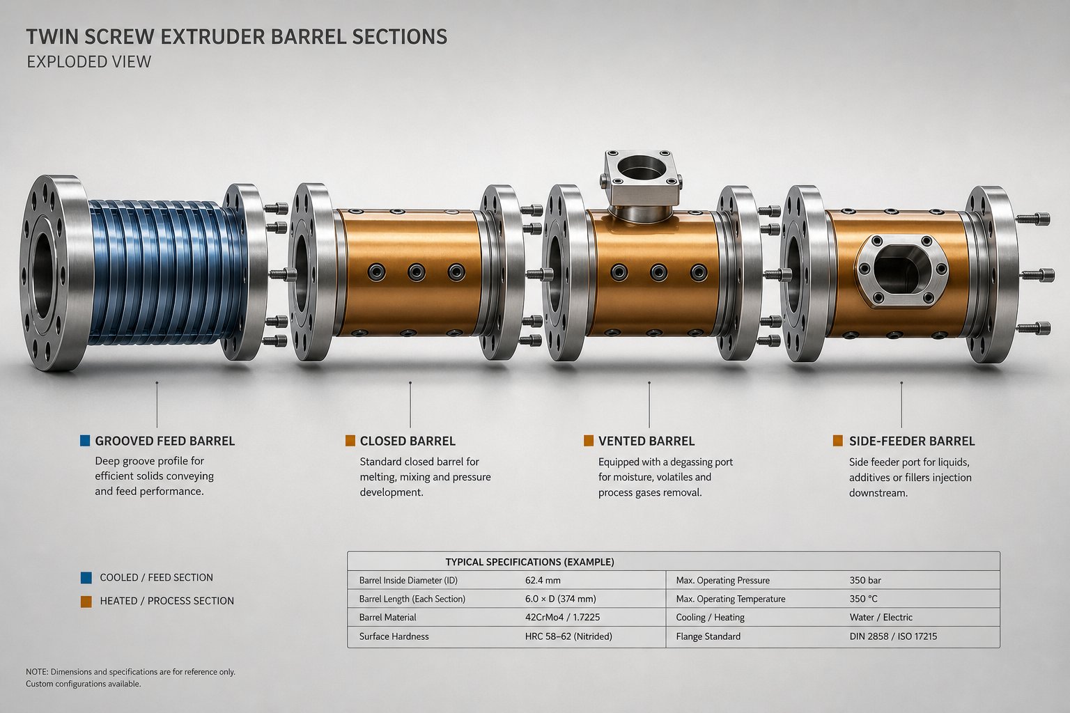
Smooth bore barrels are the standard conveying and processing segments found throughout most of the extruder barrel lineup. Their interior surface is precision-honed to a uniform cylindrical finish, providing a controlled friction environment for melting, mixing, and pressure building. You'll find smooth bore sections in the melting zone, mixing zone, and metering zone of virtually every twin screw configuration. They are the default - and when a process engineer doesn't specify a special barrel type for a given position, a smooth bore segment fills the slot.
Grooved barrels solve a very specific feeding problem. When processing slippery polymers like HDPE and PP, or when handling low-bulk-density powders, the material can simply spin with the screws instead of moving forward. Grooves machined into the bore surface - typically running axially or helically along the feed zone - increase friction between the barrel wall and incoming solids, dramatically improving solids conveying and throughput stability. As Juyuan Machinery's barrel guide notes, a grooved feeding barrel provides higher friction and increased throughput for materials like HDPE or PP, while smooth barrels are better suited for sensitive or sticky materials. The trade-off is straightforward: grooves boost grip on difficult-to-feed resins but can cause excessive shear heating if used in the wrong zone.
Vented barrels feature one or more openings - degassing ports - that allow trapped moisture, air, and volatile compounds to escape from the melt during processing. This is essential in compounding and recycling applications where incoming materials carry significant moisture content or release gaseous byproducts at processing temperatures. An extrusion barrel configured for venting typically pairs with a specific screw profile underneath: the screw elements in the vent zone are designed to create a partially filled, low-pressure region so that volatiles can escape upward through the port without melt pushing out alongside them. Atmospheric vents are common, but vacuum-assisted venting pulls even more aggressively for applications demanding very low residual moisture.
Side-Feeder and Specialty Barrel Configurations
Not every ingredient enters the extruder through the main feed throat. Glass fibers, mineral fillers, pigment concentrates, and other downstream additives are often introduced partway along the barrel extruder length through side-feeder barrel openings. These segments have a machined port on one side - sized and positioned to mate with a side-feed extruder or stuffer - allowing precise, controlled addition without disrupting the main material flow upstream. Side feeding protects fragile additives like glass fibers from excessive breakage by introducing them after the polymer has already melted, preserving fiber length and the mechanical properties of the final compound.
Liquid injection barrels serve a parallel purpose for fluid-phase additives. When formulations call for liquid plasticizers, reactive agents, peroxides, or water injection for foaming, these specialty extruder barrels include injection ports with sealing fittings and sometimes dedicated cooling zones to prevent premature reaction or volatilization at the injection point. Uniform liquid distribution into the melt depends heavily on the injection port's position relative to the screw profile underneath - placing it in a high-shear mixing zone ensures rapid incorporation.
Closed barrels - sometimes called solid barrel sections - contain no openings whatsoever. They provide maximum structural rigidity and pressure containment, making them the right choice for high-pressure zones where the screw profile generates significant back-pressure for melting, mixing, or melt sealing. As industry resources confirm, solid barrel sections maintain constant pressure and prevent material leakage, which is why they dominate the compression and metering zones of most process profiles.
The arrangement of these barrel types along the extruder length is not random - it is the process profile. Each segment position corresponds to a specific processing function, and the sequence creates the thermal, mechanical, and chemical environment that transforms raw materials into a finished compound. Here is the typical positional order you'll encounter on a standard compounding extruder from feed end to discharge:
- Grooved or smooth feed barrel - Accepts incoming raw material from the hopper; grooved versions improve solids conveying for slippery resins.
- Closed barrel segments (melting/compression zone) - Provide sealed, high-pressure containment as screw elements melt and compress the material.
- First vented barrel (atmospheric or vacuum) - Allows initial degassing of moisture and volatiles from the melt in a low-pressure screw region.
- Closed barrel segment (mixing zone) - Contains high-shear kneading and mixing elements under full pressure for dispersive and distributive mixing.
- Side-feeder barrel - Introduces downstream fillers, fibers, or additives into the already-molten polymer stream.
- Closed barrel segment (incorporation zone) - Allows newly added fillers and fibers to be mixed and distributed through the melt by downstream screw elements.
- Liquid injection barrel (if required) - Introduces liquid additives, plasticizers, or reactive agents into the compound.
- Second vented barrel (vacuum) - Removes residual volatiles and trapped air introduced with downstream fillers before the melt reaches the die.
- Closed barrel segment (metering/discharge zone) - Builds final pressure to push homogenized melt through the die head at a consistent rate.
The critical point for anyone ordering replacement extruder barrels: every segment must match the original configuration exactly. Installing a closed barrel where a vented section belongs eliminates your degassing capability and can cause trapped volatiles to blow back through upstream openings. Replacing a grooved feed barrel with a smooth bore equivalent may tank your throughput on difficult-to-feed resins. And putting a standard smooth bore segment into a side-feeder position obviously blocks downstream additive introduction entirely.
Always cross-reference the barrel position number in your machine's documentation with the segment type, bore diameter, and any port configurations before ordering. When barrel segments are lined up correctly, the process profile works as designed - but the performance of each segment still hinges on how precisely it was manufactured, which raises a question most buyers never think to ask their supplier: what tolerances and quality checks were actually applied to the parts before they shipped?
Precision Requirements and Quality Assurance for Spare Parts
A replacement barrel segment can be made from the finest bimetallic alloy on the market and still ruin your process if its bore diameter is half a tenth of a millimeter too wide. That is the unforgiving reality of twin screw extrusion: dimensional precision is not a nice-to-have manufacturing detail - it is a direct determinant of product quality, energy efficiency, and component lifespan. Yet most buyers evaluate spare parts almost entirely on material grade and price, rarely asking what tolerances the parts were machined to or what inspection methods verified those numbers before shipment.
Why Tolerances of 0.02mm Define Processing Quality
The gap between a screw element's flight tip and the barrel bore wall is one of the most performance-critical dimensions in any extruder. In twin screw machines, this radial clearance is typically measured in hundredths of a millimeter - often falling in the range of 0.08 to 0.30 mm depending on screw diameter. When that clearance grows even slightly beyond specification, the consequences ripple through every aspect of the process.
Imagine a co-rotating extruder where the self-wiping action depends on one screw's flight tip sweeping within fractions of a millimeter of its partner's root. If a replacement screw element's outer diameter is undersized by just 0.05 mm - a dimension too small to detect by eye or feel - the self-wiping geometry breaks down. Material begins stagnating in the gap, residence time increases unevenly, and thermally sensitive polymers start degrading in those dead zones. You'll see the results as gels, black specks, or discoloration in the final product long before anyone suspects the replacement element is the culprit.
Excessive clearance also creates a direct path for melt to leak backward past the screw flights rather than being conveyed forward. This backflow reduces volumetric efficiency - meaning the extruder must spin faster or longer to achieve the same throughput, increasing specific energy consumption and raising melt temperature. As industry engineering data confirms, if clearance becomes too wide due to wear or manufacturing error, material leaks backward, reducing extrusion efficiency and degrading plastic quality. Conversely, clearances that are too tight generate excessive friction and heat, potentially seizing the screw against the barrel wall and causing catastrophic damage to both components.
The same precision sensitivity extends to screw shafts and their mating surfaces. Whether you're dealing with din spline shafts on a European-built machine or a metric spline shaft from an Asian OEM, the spline tooth geometry must meet its specified tolerance class exactly. A spline bore that is even marginally oversize allows the screw element to develop angular play on the shaft, which translates into radial wobble during rotation. That wobble accelerates barrel bore wear at localized contact points, creating an uneven wear pattern that compounds with every hour of operation.
The practical threshold that separates acceptable from unacceptable is remarkably small. For most production-scale twin screw extruders, critical dimensions on screw elements and barrel bores are held to tolerances in the range of 0.01 to 0.03 mm. At this scale, visual inspection is meaningless - precision must be verified instrumentally, which is exactly where quality assurance methods come in.
Quality Assurance and Inspection Methods for Spare Parts
A reputable spare parts supplier does not ask you to trust their quality - they prove it with documented measurements. When evaluating any vendor for replacement screw elements, barrel segments, or screw shafts, you should expect - and explicitly request - specific inspection methods and the documentation that accompanies them.
Dimensional verification using CMM (Coordinate Measuring Machines) is the gold standard for confirming critical geometries. A CMM uses a precision probe to map the physical dimensions of a part in three-dimensional space, comparing actual measurements against the CAD drawing or specification sheet. For screw elements, this means verifying flight OD, root diameter, element length, bore diameter, and - critically - the spline bore profile. For barrel segments, it means confirming bore diameter at multiple points along the length, center-to-center distance between bores, and port locations on vented or side-feed sections. As IPQC quality engineering resources detail, CMMs provide the high precision and geometric versatility needed to detect deviations that no caliper or micrometer can reliably catch on complex part geometries.
Hardness testing confirms that heat treatment was performed correctly and achieved the specified surface and core hardness. Rockwell testing (HRC scale) is standard for through-hardened tool steels and hardfaced surfaces, while Vickers testing (HV scale) is better suited for thin, hard surface layers like nitriding cases. A nitrided 38CrMoAlA screw element, for example, should show HV 900-1,100 surface hardness with a case depth of 0.5-0.8 mm. If the hardness report shows values significantly below that range, the part may look identical to a properly treated one but will wear out several times faster in service. As one inspection guide puts it plainly: hardness is where a cheap screw hides - it looks identical to a good one, it just wears out several times faster.
Metallurgical analysis verifies alloy composition and confirms that the material certificate matches the actual metal in your hands. Spectrographic analysis or X-ray fluorescence (XRF) testing identifies the elemental makeup of the steel, catching substitutions - intentional or accidental - where a lower-cost alloy is supplied in place of the specified grade. This is especially important when ordering bimetallic barrels or powder metallurgy screw elements, where the wear-resistant alloy layer's composition directly determines service life.
Surface roughness measurement rounds out the quality picture. Screw elements and barrel bores must meet specified Ra (roughness average) values to ensure proper melt flow and minimize hang-up points where material can degrade. Contact profilometers dragging a diamond stylus across the surface quantify roughness in microns, confirming that grinding and polishing operations achieved the required finish.
Beyond individual test methods, the documentation package a supplier provides tells you more about their quality system than any marketing brochure. Here is what you should request - and receive - with every order of twin screw extruder spare parts:
- Dimensional inspection report - CMM or equivalent instrument measurements for all critical dimensions, referenced against the original drawing tolerances, confirming flight OD, bore dimensions, lengths, and spline profiles.
- Hardness certification - Documented Rockwell or Vickers test results at specified locations (flight tips, root, bore surface), with test method and equipment identified.
- Material certificate (mill cert) - Chemical composition analysis from the steel mill or alloy supplier, traceable to the heat or lot number, verifying that the correct alloy grade was used.
- Surface finish verification - Roughness measurements (Ra values) on critical surfaces including barrel bores, screw element flight faces, and polished areas.
- Concentricity and runout measurements - Total indicator reading (TIR) data confirming that screw shafts and assembled elements run true within specification, typically held to 0.05-0.1 mm TIR per meter of shaft length for extruder applications.
Requesting these five documents before accepting delivery is not about creating paperwork for its own sake. It is the single most effective way to separate a supplier who measures from one who hopes. A manufacturer confident in their quality will welcome the request - they already have the data because they used it to verify the parts during production. A supplier who hesitates, pushes back, or cannot produce these records is telling you something important about how those parts were actually made.
Precision manufacturing and documented quality assurance ensure that new parts arrive ready to perform - but even the best-made components eventually wear down in service. Knowing exactly when a part crosses from "still performing" to "silently degrading your process" is a skill that separates proactive maintenance programs from expensive emergency shutdowns.
How to Identify When Extruder Screws and Barrels Need Replacement
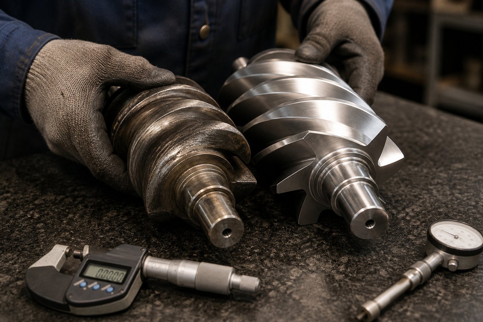
A brand-new screw element and a critically worn one can look surprisingly similar sitting side by side on a workbench. The difference between them might be a few tenths of a millimeter in flight height - invisible to the naked eye but devastating to your process. That is exactly why so many plants run worn components far longer than they should: there is no obvious "broken" moment. Instead, wear creeps in gradually, quietly eroding throughput, inflating energy bills, and degrading product quality until someone finally pulls the screw and discovers flight tips worn down to rounded nubs. By then, the barrel bore has likely suffered collateral damage too, doubling the repair cost. The alternative? Learning to read the signs - both on the parts themselves and in the process data your extruder generates every minute of operation.
Visual and Dimensional Wear Indicators
When your maintenance team pulls extruder screws for inspection, the first pass should always be visual. Before reaching for any measurement tool, lay the screw elements and shaft screw assembly on a clean, flat surface - ideally a granite inspection table - and look for these telltale signs:
- Reduced flight height on screw elements - The flight tips are the primary wear surface on any conveying or kneading element. On a new element, flight crests are sharp and uniform. Worn elements show visibly rounded or flattened tips, and in severe cases, you can see a measurable step between worn and unworn zones along the element's length. This directly increases the clearance between screw and barrel, allowing melt to leak backward over the flights instead of moving forward.
- Visible scoring or galling on surfaces - Longitudinal scratches along the barrel bore or deep grooves across screw flight faces indicate adhesive wear or foreign material contamination. Galling - where metal has smeared and transferred between screw and barrel surfaces - shows up as rough, raised patches that catch your fingernail when you drag it across the surface.
- Chipped or cracked kneading block tips - Kneading elements endure the highest shear stresses in the entire screw profile. Hairline cracks at disc edges or chipped corners signal fatigue failure. A cracked kneading block tip can break off entirely during operation, sending hardened metal fragments downstream into the die or pelletizer - causing far more expensive damage than the element itself is worth.
- Discoloration indicating overheating - Blue or straw-colored heat tinting on steel surfaces reveals that the component experienced temperatures high enough to alter its metallurgy. On a nitrided screw element, overheating can soften the hardened case layer, accelerating wear dramatically from that point forward even if the discolored area looks dimensionally acceptable.
- Pitting and surface erosion - Small craters or a roughened, orange-peel texture on flight surfaces or barrel walls point to corrosive wear from chemically aggressive polymers or their degradation byproducts.
Visual inspection tells you something is wrong, but dimensional measurement tells you how wrong. The key tools here are straightforward: a bore gauge for barrel segments, a micrometer for screw element flight diameters, and go/no-go gauges for spline bores and shaft profiles. As Adams Engineers recommends, place the screw on a clean, flat surface, examine for damage, pitting, or cracks, and then use a micrometer with a parallel test bar spanning two flights to measure outer diameter accurately. For barrels, insert the bore gauge as far down each end as possible and record measurements at multiple points to compare against original or previous values.
The critical numbers to track on the extruder screw and barrel assembly are flight OD (outer diameter) on each screw element, barrel bore ID (inner diameter) at multiple axial positions, and the resulting radial clearance between them. New screws typically have 0.002-0.004 inches (0.05-0.10 mm) clearance per side with the barrel. When that gap grows to 0.010-0.012 inches (0.25-0.30 mm), performance degrades noticeably - throughput drops, mixing suffers, and melt quality deteriorates. That threshold is your replacement trigger for mechanical wear, and tracking it over time builds the wear profile that makes future replacement timing predictable rather than reactive.
Performance Degradation as a Replacement Signal
You don't always need to stop the machine to know something is wearing out. The extruder itself broadcasts wear-related distress signals through its process data - if you know what to listen for. These performance indicators often appear weeks or months before dimensional wear reaches critical levels, giving proactive maintenance teams a valuable head start on ordering replacements.
Declining throughput at constant screw speed is frequently the first red flag. As screw flights wear and the clearance between the screw and barrel widens, polymer increasingly slips backward over the flight tips instead of being pumped forward. The result? Your extruder produces fewer kilograms per hour at the same RPM setting. Operators compensate instinctively by bumping up the screw speed, which masks the problem temporarily but accelerates wear further. Tracking the ratio of output rate (kg/hr or lb/hr) to screw RPM over months reveals a declining trend that correlates directly with flight wear. Industry monitoring data suggests that when operators have increased screw RPM by 15-20% to maintain output, it is time for a screw pull and measurement.
Increased specific energy consumption (kWh/kg) signals that the extruder is working harder to achieve the same result. Worn elements change the melting and mixing dynamics, and the motor draws more power per unit of output to compensate. This metric is one of the most sensitive indicators of shaft screw and element condition - subtle increases of 10-15% above the established baseline warrant investigation even when throughput still appears acceptable.
Deteriorating melt quality shows up in your product before it shows up on any gauge. Rising gel counts, poor filler dispersion, inconsistent color distribution, and visible unmelts all point toward screw elements that can no longer generate adequate shear or mixing action. In compounding operations, a quality control team that suddenly sees dispersion scores trending downward should alert maintenance - not just the process engineer adjusting barrel temperatures.
Rising melt temperature without process changes is a counterintuitive but reliable symptom. As flight clearances widen, material slipping over worn flights generates additional frictional heat. The melt runs progressively hotter than barrel setpoints, sometimes by 8-15 degrees Fahrenheit above baseline before anyone notices. At that point, the thermal damage to the polymer may already be affecting product properties.
Increased motor amperage at constant screw speed rounds out the picture. Changes in motor load reflect altered melting behavior, increased back-pressure from wear compensation, or screw deflection contacting the barrel - all symptoms of components past their useful life.
Proactive scheduled replacement based on measured wear data is always more cost-effective than emergency replacement after catastrophic failure. A planned screw swap during a scheduled shutdown costs a fraction of an unplanned seizure that damages both screws and barrels simultaneously - often turning an $8,000-$25,000 screw replacement into a $30,000-$150,000 emergency event including barrel repairs, expedited parts, and days of lost production.
Building a preventive maintenance schedule around these indicators transforms spare part replacement from guesswork into a data-driven decision. Here is a practical framework for inspection intervals and measurement techniques that keeps your screw and barrel condition under continuous surveillance:
- Every 500-1,000 operating hours - Measure screw flight OD and barrel bore ID at multiple axial positions using micrometers and bore gauges. Record all values and compare against baseline and previous readings to track clearance growth trends.
- Weekly (during operation) - Log motor amperage, screw RPM, output rate, and melt temperature at standardized operating conditions. Calculate and trend the output-per-RPM ratio and specific energy consumption (kWh/kg).
- Monthly - Review melt quality data (gel counts, dispersion scores, color consistency) alongside maintenance trend logs. Correlate any quality degradation with wear trend data to determine if component condition is the root cause.
- Every scheduled shutdown - Perform visual inspection of accessible screw elements and barrel bores for scoring, galling, discoloration, and cracking. Use go/no-go gauges on spline bores to check for looseness. Roll the screw shaft on a granite table and check straightness with feeler gauges.
- After every 2-3 measurement cycles - Plot clearance growth over time to establish a wear rate curve specific to your material, screw metallurgy, and operating conditions. Use this curve to predict when clearance will reach the replacement threshold - then order parts in advance to arrive before that date.
The pattern here is clear: consistent measurement creates predictability, and predictability eliminates the emergency scramble that turns a manageable parts expense into a budget-breaking crisis. Knowing when to replace is half the equation - the other half is knowing where to source those replacements and how to evaluate whether a supplier's parts will actually meet the specifications your measurements just validated.
Sourcing Aftermarket Spare Parts and Evaluating Suppliers
Your measurement data says the screws need replacing. You know the exact spline type, the material grade, the dimensional tolerances, and the barrel configuration. The question shifts from what to buy to where to buy it - and that decision introduces its own set of trade-offs. Should you go straight to the original equipment manufacturer, or can an aftermarket supplier deliver equivalent performance at a lower cost and faster turnaround? The answer depends entirely on what you verify before placing the order.
OEM vs Aftermarket Spare Parts - What to Verify
OEM parts carry one undeniable advantage: they are manufactured to the exact specifications of the original design. When you order a set of screw elements directly from the extruder manufacturer, you know the material grade, heat treatment, tolerances, and spline profile will match what came with the machine. For plants running critical applications - pharmaceutical compounding with strict validation requirements, or automotive-grade engineering plastics where material traceability is contractually mandated - that certainty can justify the premium.
The trade-offs, however, are real. OEM replacement parts frequently carry higher price tags and longer lead times than aftermarket alternatives. Some OEM manufacturers route spare part orders through regional distributors who add markup without adding value. Lead times of 8 to 16 weeks for screw elements or barrel segments are not unusual from major European or Japanese extruder OEMs, and for plants facing an unplanned shutdown, that timeline can translate into hundreds of thousands of dollars in lost production.
Aftermarket parts - components manufactured by third-party suppliers rather than the original extruder maker - can bridge that gap. The key word is can. A well-made aftermarket screw element, machined from the same alloy grade, heat-treated to the same hardness specification, and ground to the same dimensional tolerances as the OEM original, will perform identically in service. An aftermarket part made from a cheaper substitute alloy with loose tolerances will fail prematurely and potentially damage adjacent components. The difference between these two outcomes is not luck - it is verification.
Before accepting any aftermarket replacement part, verify these quality benchmarks against the OEM specification:
| Quality Benchmark | What to Request | Why It Matters |
|---|---|---|
| Material Certification | EN 10204 3.1 mill certificate or equivalent spectrographic analysis for every alloy used - base material, hardfacing, and liner | Confirms the correct alloy grade was actually used, catching substitutions where a lower-cost steel replaces the specified CPM or tool steel grade |
| Dimensional Inspection Report | CMM measurements for flight OD, bore diameter, element length, spline profile, and center distances, referenced against the original drawing | Verifies that critical clearances will fall within the OEM tolerance band; even 0.03 mm deviation can compromise self-wiping action |
| Hardness Test Results | Rockwell (HRC) or Vickers (HV) readings at multiple locations - flight tips, root, bore surface - with test method and equipment identified | Confirms heat treatment achieved specification; underperforming hardness is invisible to the eye but cuts service life dramatically |
| OEM Part Number Cross-Reference | Written confirmation that the aftermarket part number maps to the specific OEM part number for your extruder model and serial number | Prevents ordering dimensionally similar parts designed for a different machine model - a common and expensive mistake |
One nuance worth noting: aftermarket parts are sometimes produced by the same contract manufacturers that supply OEM brands. A spline shaft machined in the same CNC facility, from the same steel heat, to the same drawing - but sold through an aftermarket channel rather than the OEM's distribution network - is functionally identical to the OEM part. As industry analysis confirms, sometimes an aftermarket part is even produced by the same factory that made the OEM version but then rebranded or sold through different channels. The documentation trail is what proves this equivalence, not the brand name on the invoice.
For widely used extruder platforms - Coperion ZSK series, Leistritz ZSE models, CPM century extrusion systems, and similar production-standard machines - a robust aftermarket ecosystem exists precisely because the installed base is large enough to justify independent manufacturing. Spline shaft manufacturers, element producers, and barrel fabricators have reverse-engineered and validated parts for these common platforms over decades. The sourcing risk is lower when multiple qualified aftermarket suppliers compete on quality and price for the same part geometry. For less common or proprietary machines, the aftermarket options narrow, and additional due diligence on dimensional verification becomes essential.
Evaluating Suppliers and Sourcing with Confidence
Choosing between OEM and aftermarket is only half the sourcing decision. The other half - arguably the more consequential half - is evaluating the specific supplier you'll rely on for consistent quality, accurate lead times, and technical support when specifications get complicated. Not every aftermarket vendor is equal, and industrial component sourcing research consistently identifies the same set of criteria that separate reliable suppliers from risky ones.
Manufacturing capabilities deserve your first question: what production steps does the supplier perform in-house versus outsource? A supplier who controls CNC machining, precision grinding, heat treatment, and hardfacing under one roof has direct control over the variables that determine field life. When heat treatment is outsourced to a shared commercial furnace, cycle parameters are standardized rather than optimized for your specific alloy and geometry. When hardfacing is subcontracted, deposition parameters may default to generic settings. Each outsourced step introduces variability that shows up as inconsistent part performance - some batches last 12,000 hours, others fail at 5,000, with no clear explanation. As sourcing guides from the extrusion industry emphasize, vertical integration is increasingly the difference between a supplier and a trader.
Part range breadth matters more than most buyers realize. Sourcing screw elements from one vendor, barrels from another, spline shafts from a third, and heater bands from a fourth multiplies your procurement workload, increases the risk of specification mismatches across vendors, and eliminates single-point accountability when something doesn't fit. Suppliers who stock spline shafts alongside screw elements, barrel segments, and auxiliary components can cross-check dimensional compatibility across the full assembly before anything ships - a quality advantage that multi-vendor sourcing cannot replicate.
Custom manufacturing ability becomes critical when your machine is older, modified, or built by a manufacturer that no longer exists. The ability to produce replacement parts from your own drawings, CAD files, or even worn physical samples separates genuine manufacturers from catalog resellers. Many plants running legacy CPM century extrusion equipment or discontinued models from smaller brands face exactly this challenge - OEM parts are unavailable, and the only path to replacement runs through a supplier capable of reverse engineering and precision manufacturing from scratch.
For teams seeking a single-source supplier that covers the full spectrum - from screw elements and barrels to spline shafts, heater bands, die heads, and custom-machined components - evaluating candidates against a structured criteria list prevents the common trap of choosing based on price alone. Here are the evaluation factors that consistently predict long-term supplier reliability:
- Comprehensive product range with custom capability - NANHAIYA's extruder spare parts catalog illustrates what a full-range aftermarket supplier looks like in practice: screw elements, barrels, shafts, heater bands, thermocouples, die heads, pelletizing blades, and custom parts manufactured from drawings or samples - all from a single source supporting maintenance teams, machine rebuilders, and plant procurement departments.
- Material certifications - The supplier provides EN 10204 3.1 mill certificates, spectrographic analysis, or equivalent documentation for every alloy used in every part. No certificates, no confidence.
- Dimensional inspection capability - CMM equipment or equivalent precision measurement systems are available on-site, and inspection reports accompany every shipment with measurements referenced against drawing tolerances.
- In-house heat treatment and surface finishing - Critical metallurgical processes are controlled directly rather than outsourced, ensuring consistency from batch to batch and part to part.
- Lead time reliability - The supplier commits to documented lead times, communicates proactively about any delays, and maintains inventory of common wear parts and stock components. Spline shaft suppliers who keep standard shaft blanks in inventory, for example, can cut delivery time significantly compared to those who manufacture entirely to order.
- After-sales technical support - Engineers at the supplier can discuss material selection, wear mechanisms, and dimensional specifications rather than simply taking part numbers and quoting prices. This capability matters most when troubleshooting unexpected wear patterns or specifying parts for a new compound formulation.
- Industry experience and references - Years of serving the extrusion industry translate into accumulated knowledge about platform-specific nuances, common failure modes, and proven material solutions. Request references from other customers processing similar materials on similar equipment.
One practical step many procurement teams skip: request a sample part before committing to a production order. A single screw element or barrel segment, inspected against the OEM drawing with hardness verification and dimensional checks, reveals more about a supplier's true capability than any sales presentation or factory tour. If the sample meets specification, you have evidence-based confidence. If it doesn't, you've invested a few hundred dollars instead of discovering the problem after a $15,000 order arrives and fails in service.
The entire framework presented throughout this article - from understanding part categories and shaft configurations, through wear mechanisms and barrel types, to precision requirements and replacement timing - ultimately serves a single purpose: enabling your team to source twin screw extruder spare parts based on verified knowledge rather than assumptions. Every specification you document, every wear measurement you record, and every supplier certification you verify removes one more variable from the equation. What remains is a procurement decision grounded in engineering data, matched to your actual process conditions, and backed by the quality documentation that turns a purchase order into a performance guarantee.
Frequently Asked Questions About Twin Screw Extruder Spare Parts
1. What are the most commonly replaced twin screw extruder spare parts?
The most frequently replaced components are screw elements (conveying elements and kneading blocks), barrel segments, and feed screws, since they endure constant abrasive and thermal stress. Depending on the processed material, nitrided steel screws and barrels may last only 3 to 12 months. Auxiliary parts like heater bands, thermocouples, pelletizing blades, and die heads also require periodic replacement. Suppliers such as NANHAIYA (nhyscrews.com) offer the full range of these components, including custom manufacturing from drawings or samples, which simplifies procurement for maintenance teams.
2. Can I use aftermarket spare parts instead of OEM parts for my twin screw extruder?
Yes, aftermarket spare parts can deliver OEM-equivalent performance when they are manufactured to the same alloy grade, heat treatment specification, and dimensional tolerances as the original. The key is verification: request material certifications (EN 10204 3.1 mill certificates), CMM dimensional inspection reports, hardness test results, and OEM part number cross-references before accepting delivery. In some cases, aftermarket parts are produced by the same contract factories that supply OEM brands. Ordering a sample part first and inspecting it against the OEM drawing is a low-cost way to validate a new supplier's true capability.
3. How do I know when my extruder screws and barrels need replacement?
Watch for both physical and process-level indicators. Physically, look for reduced flight height, scoring or galling on surfaces, cracked kneading block tips, and heat discoloration. On the process side, declining throughput at constant screw speed, rising specific energy consumption (kWh/kg), deteriorating melt quality (gels, poor dispersion), and increased motor amperage all signal worn components. Measure screw flight OD and barrel bore ID every 500 to 1,000 operating hours using micrometers and bore gauges. When radial clearance grows to approximately 0.25-0.30 mm, plan for replacement before performance degrades further.
4. Are co-rotating and counter-rotating twin screw extruder parts interchangeable?
No, parts are absolutely not interchangeable between co-rotating and counter-rotating configurations. Co-rotating machines use self-wiping, intermeshing screw elements with specific lobe profiles (bi-lobal or tri-lobal) and tight clearances, while counter-rotating systems have fundamentally different flight geometries, clearance specs, and barrel designs. Before ordering any replacement, verify the rotation direction, lobe count, element flight geometry, bore center distance, and shaft spline type against your machine documentation. Installing the wrong configuration can destroy both screws and barrels within hours of operation.
5. What material should I choose for replacement extruder screws and barrels?
Material selection should match your specific wear environment rather than defaulting to the most expensive option. For unfilled polymers with moderate abrasion, nitrided steel (38CrMoAlA) offers cost-effective performance. Heavily filled compounds with glass fiber or minerals demand bimetallic barrel linings or powder metallurgy tool steels like CPM 9V or CPM 10V. Corrosive applications processing PVC or fluoropolymers require high-chromium alloys or nickel-based options such as Inconel. Surface treatments like tungsten carbide coatings or Stellite hardfacing add targeted protection at high-wear zones. Matching the material to the actual wear mechanism - abrasive, adhesive, or corrosive - delivers the best cost-to-performance ratio.
Written by
Nanhaiya Technical Team
Zhoushan Nanhaiya Plastic Machinery Co., Ltd.
The Nanhaiya technical team supports screw and barrel manufacturing projects through application review, technical communication, custom manufacturing coordination, and production and quality control.
Discuss Your Application
Related Articles
More insights on screw barrel technology and plastics processing.

What Nobody Tells You About Screw Barrel For Plastic Machine Design
Oct 10, 2026
Learn how screw barrel for plastic machine design affects melt quality, throughput, and wear life. Covers geometry, resin matching, troubleshooting, and sourcing.
Read Article
Single Screw Extruder for Sheet: Stop Guessing, Start Specifying
Oct 9, 2026
Learn how to specify a single screw extruder for sheet production. Covers screw geometry, resin-specific processing, troubleshooting, and maintenance best practices.
Read Article
PE Pipe Extruder Machine: What Datasheets Won't Tell You
Oct 9, 2026
Learn how a PE pipe extruder machine works, key specs explained, material grade selection, maintenance tips, and buyer guidance beyond the datasheet.
Read ArticleLooking for something else?
Search by material, symptom or product and jump straight to the relevant page.
These are navigation suggestions based on keyword matching — not a quotation, not a delivery commitment, and not a substitute for engineering review. Final specification is confirmed by our engineers against your drawings and processed material.
Need help with screw barrel selection?
Share your machine model, processed material and application. Our team can help with pricing and technical support.