

What Is a Twin Screw Extruder Shaft and Why It Matters
Imagine the twin screw extruder on your production floor running at full capacity — tons of polymer melt being conveyed, mixed, and pushed through the die every hour. What single component carries all of that rotational force from the gearbox to the material? It's not the screw elements you can see and swap out. It's the shaft hidden beneath them.
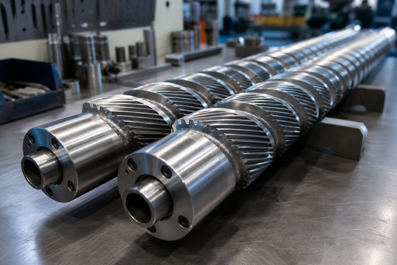
A twin screw extruder shaft is the central, torque-transmitting steel component that runs the full length of the processing section inside a twin screw extruder. Connected to the gearbox at one end and supporting modular screw elements along its splined surface, the shaft transfers rotational energy from the drive system to the screw elements, which in turn convey, melt, mix, and pressurize materials within the barrel bore.
That definition matters more than it might seem at first glance. Many engineers — even experienced ones — use the terms "shaft" and "screw" interchangeably. They're not the same thing, and confusing them leads to costly specification errors when ordering replacements.
Definition and Core Function of the Extruder Shaft
Think of the shaft as the load-bearing backbone of the entire screw assembly. Every screw element — whether it's a conveying element, a kneading block, or a mixing disc — slides onto the shaft and locks into position via a splined connection. The shaft's job is straightforward but mechanically demanding: transfer every bit of torque generated by the motor and gearbox into those individual elements while keeping them in precise rotational alignment inside the barrel.
In a twin screw extruder, the transmission system converts motor power into the rotational movement of two parallel shafts. As industry references explain, the kinetic energy in that rotational movement becomes torsional force — and the greater the torsion a shaft can handle, the more material the extruder can process. That's why the shaft is often called the "heart" of the machine. It doesn't just spin; it carries the full mechanical load that defines your throughput ceiling.
This applies to both co-rotating designs, where the two shafts turn in the same direction for dispersive mixing, and counter-rotating configurations, where they turn in opposite directions for gentler processing or profile extrusion.
Where the Shaft Fits in the Extruder Assembly
Visualize the mechanical chain from power source to material output. The electric motor generates rotational speed. The gearbox — specifically the torque distribution box — reduces that speed and splits the torque evenly between two parallel output shafts. Each shaft then extends through a series of modular barrel segments, carrying a custom arrangement of screw elements along its length.
The shaft itself is a precision-ground steel bar with external splines running along most of its working length. Screw elements slide over these splines and are held in sequence by a tip bolt or locking mechanism at the discharge end. The barrel segments surround both shafts and their elements, creating the enclosed processing chamber where materials are transformed.
Here's the critical distinction: screw elements are the interchangeable, application-specific parts you reconfigure for different recipes. The shaft is the permanent, high-strength foundation they all depend on. When a shaft wears, warps, or cracks, every element on it loses alignment — and your entire process is compromised.
This resource is built to bridge the gap between shallow product listings and narrow academic papers. Whether you're a maintenance engineer diagnosing a recurring failure, a process engineer optimizing torque utilization, or a procurement professional sourcing a replacement, the sections ahead cover what you actually need to know — from spline geometry and material selection to failure prevention and sourcing strategy. The engineering challenges that make these shafts so uniquely difficult to design are where that story begins.
How Twin Screw Shafts Differ from Single Screw Designs
A single screw extruder gives its shaft all the room it needs. One shaft, one barrel bore, and plenty of cross-sectional area to handle torque loads. A twin screw extruder shaft doesn't get that luxury. Two shafts must operate side by side inside a figure-eight barrel bore, and that fundamental geometric constraint changes everything about how these shafts are engineered. Understanding these differences helps explain why twin screw shafts fail in ways that single screw shafts simply don't.
Center Distance Constraints and Diameter Limitations
Picture two parallel shafts spinning inside a shared barrel. The center-to-center distance between them has to be small enough for the screw elements to intermesh — that's what gives twin screw extruders their superior mixing and conveying performance. But that tight spacing creates a serious mechanical trade-off.
When center distance shrinks, maximum shaft diameter shrinks with it. And shaft diameter directly determines how much torque the shaft can transmit. As parallel twin screw design analysis highlights, the limited space between two screw axes also restricts the size of radial and thrust bearings inside the gearbox — resulting in smaller gear modules, smaller shaft tail diameters, and ultimately lower torque resistance. This is widely recognized as the most significant structural challenge of parallel twin screw extruder design.
In a single screw system, you'll never face this problem. The shaft can be as thick as the barrel bore allows. In a twin screw system, every millimeter of shaft diameter is a hard-fought engineering compromise between torque capacity, intermeshing depth, and available free volume for material processing.
Specific Torque Challenges in Twin Screw Configurations
Here's where things get especially demanding. Twin screw extruder shafts must deliver higher torque density — meaning more torque per unit of cross-sectional area — than their single screw counterparts. Why? Because they carry comparable or greater total process loads through a significantly smaller shaft diameter.
The shaft is actually what limits torque transmission in a twin screw extruder. As Leistritz's technical reporting explains, the screw shaft rating — denoted in Newton-meters — depends on cross-sectional area, shaft metallurgy, spline geometry, and the shaft hardening process. State-of-the-art designs use asymmetrically splined shafts to transmit power from the motor and direct a tangential force vector into the screws, squeezing maximum torque capacity from a physically constrained diameter.
This torque density challenge drives nearly every downstream engineering decision. Material selection moves toward higher-strength alloy steels. Heat treatment processes become more critical. Spline profiles must be optimized for load distribution rather than manufacturing convenience. A single screw shaft can often get by with simpler designs because it has cross-sectional area to spare — a twin screw shaft cannot afford that margin.
Co-Rotating vs. Counter-Rotating Shaft Geometry Differences
Not all twin screw extruder shafts face the same challenges, either. The direction of rotation fundamentally changes the load profile each shaft experiences.
In a co-rotating twin screw extruder, both shafts spin in the same direction with a fully intermeshing geometry. This design produces intense shear fields between the screws and between the screw and barrel, creating high torque demands and significant cyclic loading. To handle these forces, co-rotating machines typically use involute spline shafts that distribute torque loads across a larger contact area, maximizing the power each shaft can carry.
Counter-rotating designs work differently. The two shafts turn in opposite directions, and mixing relies more on compressive and elongational deformation than on the high-shear forces characteristic of co-rotating systems. Torque loads tend to be lower and more consistent, which means counter-rotating shafts can sometimes use simpler spline profiles or keyway connections. These machines often operate at lower rotational speeds and higher fill levels, further reducing peak shaft stress.
The table below summarizes how these three shaft configurations compare across the most important engineering dimensions:
| Characteristic | Single Screw Shaft | Co-Rotating Twin Screw Shaft | Counter-Rotating Twin Screw Shaft |
|---|---|---|---|
| Shaft Diameter Flexibility | High — full barrel bore available | Low — constrained by center distance | Low to moderate — conical designs offer more room at the feed end |
| Typical Spline Type | Keyway or simple spline | Involute spline (often asymmetric) | Straight spline, keyway, or involute depending on size |
| Torque Density Challenge | Low | Very high | Moderate |
| Intermeshing Requirement | None | Fully intermeshing, self-wiping | Fully or partially intermeshing |
| Primary Load Type | Steady torsional | High cyclic torsional + bending | Compressive + moderate torsional |
| Synchronization Precision | Not applicable | Critical — exact phase alignment required | Important — opposite rotation must be timed |
You'll notice the pattern: every advantage that makes twin screw extruders better at mixing and processing also makes their shafts harder to engineer. The co-rotating configuration pushes these demands to the extreme. Smaller diameter, higher torque density, more complex spline geometry, and tighter synchronization all converge on a single component that has very little room for error.
These constraints are exactly why spline profile selection becomes such a critical design decision — one that determines not just how much torque a shaft can carry, but how long it can carry that torque before wear, fatigue, or failure sets in.
Shaft Design Principles and Spline Profile Types
Spline profile selection is one of those decisions that gets made once during extruder design — and then dictates maintenance headaches (or the lack of them) for the next decade. The profile machined into your twin screw extruder shaft determines how torque spreads across every screw element, how the shaft centers itself under load, and how quickly wear accumulates at each contact surface. Yet most technical resources skip right over this topic. Let's fix that.
Involute Splines and Their Torque Advantages
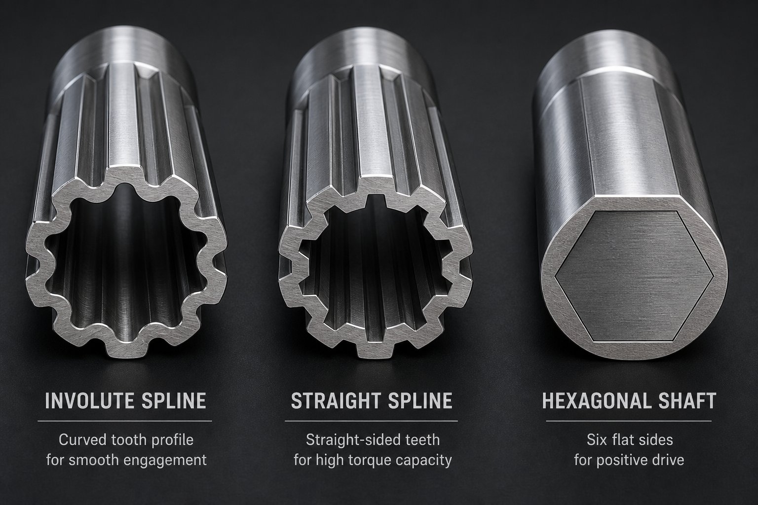
If you've looked inside any modern co-rotating twin screw extruder, the shafts almost certainly feature involute splines. The tooth profile follows the same involute curve geometry used in gear teeth — except the teeth are shorter and don't roll against a mating gear. Instead, they lock into matching grooves inside each screw element bore.
Why does this curved profile dominate high-performance extruder shafts? Three mechanical advantages set it apart.
First, involute splines distribute load evenly across all teeth, rather than concentrating stress at tooth edges. In a twin screw extruder shaft already constrained to a small diameter, that uniform load distribution directly translates into higher usable torque capacity from the same physical envelope.
Second, involute profiles are naturally self-centering under load. When torque is applied, the pressure angle of the teeth creates a radial force component that pulls the shaft and element into concentric alignment. Straight splines lack this ability entirely — they rely on manual centering through tight diameter fits. For a shaft spinning at hundreds of RPM inside a precisely bored barrel, self-centering isn't a convenience; it's a requirement for preventing metal-to-metal contact between screw elements and barrel walls.
Third, the gradual tooth engagement of involute geometry produces smoother contact with less impact and vibration. This translates directly into superior fatigue resistance — a critical advantage when the shaft endures millions of loading cycles over its service life. The smoother meshing also reduces the friction-driven wear that eventually degrades spline surfaces.
The trade-off? Involute splines are more complex and costly to manufacture. They require precision hobbing, shaping, or grinding operations, and post-heat-treatment distortion must be carefully managed to maintain accurate tooth profiles.
Straight Splines and Hexagonal Bore Alternatives
Not every extruder demands involute complexity. Counter-rotating machines, older extruder models, and some smaller-diameter systems use parallel-sided (straight) splines or hexagonal bore connections — and for good reason.
Straight splines feature rectangular ridges evenly distributed around the shaft circumference, with both sides of each tooth running parallel to the shaft axis. Their biggest advantage is simplicity. As spline engineering guides note, rectangular splines are straightforward to manufacture, low in cost, and easy to assemble and disassemble — all valuable qualities when you're maintaining equipment in the field.
However, straight splines concentrate stress at tooth edges rather than distributing it across the full flank. This uneven loading accelerates localized wear, particularly under the high cyclic loads found in twin screw extrusion. They also offer no self-centering capability, meaning any clearance between shaft and element creates wobble, vibration, and accelerated degradation. Even slight misalignment can be detrimental, causing higher stress accumulation on edges and more frequent replacement cycles.
Hexagonal bore connections take simplicity a step further — a six-sided shaft profile mates with a matching hexagonal bore in the screw element. You'll find these primarily on lab-scale and pilot extruders where torque loads are modest, production uptime pressure is lower, and the ability to quickly swap elements during R&D trials matters more than maximum torque density. The obvious limitation is that only six contact faces share the entire torque load, making this design unsuitable for production-scale machines.
Spline Fit Classes and Tolerances
Choosing the right spline profile is only half the equation. How tightly that profile fits its mating element is equally important — and this is where many shaft failures actually originate.
Spline connections are specified as either side fit or major-diameter fit, and the distinction has real consequences for your extruder's performance. In a side-fit spline, clearance exists at both the root and outside diameters, and the fit is controlled by the difference between the external tooth thickness and the internal space width. The teeth themselves center the connection under load, thanks to the pressure angle forcing concentricity. This makes side-fit configurations the preferred choice for most twin screw extruder applications where self-centering matters.
Major-diameter fit splines work differently. The outside diameter of the shaft and the major diameter of the element bore act as pilots, centering the connection through diameter contact rather than tooth contact. Sounds precise, but there's a catch: any concentricity error between the pilot diameter and the pitch diameter of the teeth means only some teeth effectively carry torque. As spline engineering literature explains, this reduces the effective capacity and strength of the entire connection.
Tolerance classes add another layer. Under the SAE B92.1 standard, involute splines are manufactured to tolerance classes 4, 5, 6, or 7 — with higher numbers representing greater precision. Tighter tolerances reduce backlash, minimize fretting wear at element-to-shaft interfaces, and ensure more uniform torque distribution across every element on the shaft. For twin screw extruders, where dozens of elements stack onto a single shaft, even small per-element clearances compound into significant cumulative play that accelerates wear.
Actual tooth dimensions are typically verified by over-pin or between-pin measurements for individual teeth. Effective dimensions — accounting for involute error, lead variation, and spacing deviations — represent the worst-case material condition across all teeth and are checked using go/no-go spline gauges. This dual-measurement approach catches both individual tooth defects and systemic profile errors that would otherwise go undetected until they cause operational problems.
Here's a quick reference for matching spline types to application scenarios:
- Involute splines: Best for co-rotating production extruders requiring maximum torque density, self-centering under load, and long fatigue life.
- Straight (parallel-sided) splines: Best for counter-rotating or older extruder models where simpler manufacturing, easy field assembly, and lower cost outweigh torque capacity requirements.
- Hexagonal bore connections: Best for lab-scale and pilot extruders where low torque loads, rapid element changeover, and minimal tooling investment are priorities.
Profile geometry and fit tolerances define how efficiently a shaft transmits torque — but they don't determine how long the shaft survives under that torque. That durability question comes down to what the shaft is made of and how its surface is treated, which introduces an entirely different set of engineering trade-offs.
Material Selection Criteria for Extruder Shafts
You can design the perfect spline profile, machine it to the tightest tolerance class, and still watch your twin screw extruder shaft fail prematurely — if you chose the wrong material. Spline geometry determines how torque is distributed. Material determines how long the shaft survives that torque under real-world conditions: cyclic loading, abrasive fillers, corrosive polymers, and operating temperatures that can swing hundreds of degrees during a single production run.
Despite how critical this decision is, twin screw extruder shaft material selection remains one of the most poorly documented topics in the industry. Most OEM documentation lists a steel grade without explaining why it was chosen or when an alternative would perform better. Procurement teams order replacements by matching a part number, not by evaluating whether the original material was even the right choice for their specific process. That gap costs real money in premature failures and unnecessary downtime.
Three broad material categories dominate extruder shaft manufacturing today. Each represents a fundamentally different philosophy for balancing hardness, toughness, corrosion resistance, and cost. Understanding these trade-offs puts you in a position to specify the best material for your twin screw extruder shaft — not just the default one.
Nitrided Steel Grades for Surface Hardness and Wear Resistance
Walk into any polymer compounding plant running production-scale twin screw extruders, and the shafts inside those machines are almost certainly made from nitrided alloy steel. This combination of a tough alloy steel core with a nitrogen-diffused hard surface layer has become the industry standard — and for good reason.
Nitriding is a thermochemical surface treatment that diffuses nitrogen into the steel at relatively low temperatures, typically below the material's transformation range. Unlike carburizing or through-hardening, nitriding doesn't require a quench step, which means the shaft experiences minimal dimensional distortion during treatment. For a precision component covered in involute splines, that dimensional stability is a major practical advantage.
The mechanical benefits go deeper than surface hardness alone. Research from Advanced Heat Treat Corp. shows that nitriding creates compressive residual stresses near the surface — reaching values around -400 MPa in tested alloy steels. These compressive stresses directly oppose the tensile stresses generated during bending and torsional loading, effectively raising the shaft's fatigue threshold. A nitrided steel shaft subjected to bending and rotation has its maximum resultant stress pushed below the surface and significantly reduced compared to an untreated part, resulting in dramatically increased fatigue life.
The wear resistance improvements are equally significant. Nitriding creates a compound layer at the very surface, followed by a deeper diffusion zone where nitrogen atoms occupy interstitial positions in the steel's crystal lattice. The compound zone provides exceptional resistance to abrasive and adhesive wear — critical for spline surfaces where screw elements slide on and off during assembly and experience micro-motion under cyclic loading. Testing on nitrided alloy steels has demonstrated surface hardness values exceeding 1300 HV in optimized processes, with linear wear remaining remarkably low even under contact pressures of 200 MPa.
Common base steels for nitrided extruder shafts include chromium-molybdenum and chromium-molybdenum-vanadium alloy grades. The vanadium-containing grades form particularly stable nitrides that resist softening at elevated temperatures — an important consideration when barrel temperatures push past 300 degrees Celsius during engineering polymer processing.
The limitation? Nitriding is a surface treatment, not a through-property modification. The hard case typically extends less than one millimeter into the shaft surface. If wear progresses beyond the nitrided case, or if the shaft experiences impact loading severe enough to crack through the hard layer, the softer core material is quickly exposed. That's why nitrided steel extruder shaft wear resistance depends on the process being operated within its design envelope — excessive torque spikes or contamination with hard particulates can overwhelm the nitrided surface faster than expected.
Through-Hardened Tool Steels for High-Torque Applications
Some extrusion processes simply exceed what a nitrided alloy steel shaft can handle. Imagine compounding heavily filled masterbatches with 70% or more calcium carbonate, processing glass-fiber-reinforced engineering plastics, or running reactive extrusion chemistries that generate extreme torque spikes during cross-linking. These applications demand a shaft with high hardness not just at the surface, but throughout its entire cross-section.
Through-hardened tool steels answer that demand. These are high-alloy steels — often containing elevated levels of chromium, vanadium, molybdenum, and tungsten — that achieve high bulk hardness via conventional quench-and-temper heat treatment. The result is a shaft that resists deformation and wear uniformly from surface to core.
The torque capacity advantage is straightforward: when the full cross-section of the shaft contributes to load-bearing capability rather than just a thin hardened skin, the shaft can tolerate higher peak loads without permanent deformation. For twin screw extruder shafts already constrained to small diameters by center-distance limitations, squeezing more torque capacity from the available material volume is a meaningful engineering gain.
The trade-offs, however, are significant. Through-hardened tool steels sacrifice toughness for hardness. A nitrided alloy steel shaft with a relatively soft, ductile core can absorb occasional impact loads by yielding slightly without fracturing. A through-hardened tool steel shaft is more brittle — it resists deformation right up to the point where it doesn't, and when it fails, it tends to crack rather than bend. This makes tool steel shafts more susceptible to catastrophic fracture if subjected to sudden torque overloads, jammed screws, or thermal shock.
Cost is the other consideration. Tool steels are significantly more expensive as raw materials, and their heat treatment requires tighter process control to achieve consistent hardness without introducing quench cracks. Machining costs also run higher because tool steels in their hardened state are much more difficult to cut, grind, and finish. For many standard compounding applications, this cost premium delivers no meaningful performance benefit over a well-specified nitrided alloy steel shaft.
Stainless and Specialty Alloys for Corrosive Environments
What happens when your extrusion process involves materials that attack the shaft chemically? Pharmaceutical compounds, food ingredients containing moisture and salt, PVC formulations releasing hydrochloric acid during processing, and certain biopolymers all create corrosive environments inside the barrel. In these applications, even the best nitrided alloy steel or tool steel will eventually suffer corrosion-accelerated wear, pitting, and stress corrosion cracking.
Stainless steel shafts solve the corrosion problem — but they introduce their own mechanical compromises. Most austenitic stainless steels (the 300 series) offer excellent corrosion resistance but relatively low hardness and limited wear resistance, making them poor candidates for extruder shafts without additional surface treatment.
Martensitic stainless steels offer a much better balance for extrusion applications. As food and pharmaceutical extruder material studies confirm, the 440 series martensitic stainless steels can achieve hardness values of HRC 58-62 after quenching, combining high wear resistance with genuine corrosion protection. The 440C grade, in particular, has become a go-to choice for food and pharmaceutical extruder components that must withstand alkaline corrosion, salt exposure, and repeated cleaning cycles while maintaining dimensional stability under load.
For even more demanding corrosive environments, some manufacturers specify precipitation-hardened stainless steels like 17-4 PH, which can be nitrided to further enhance surface properties. Plasma nitriding of 17-4 PH stainless steel has been studied extensively, and the process can significantly improve wear and fatigue performance while preserving the alloy's inherent corrosion resistance.
The mechanical trade-off with stainless steels is real, though. Even hardened martensitic grades don't match the core toughness-to-hardness ratio of purpose-designed nitriding steels. Their thermal conductivity is lower, which can affect heat dissipation along the shaft during high-speed processing. And cost runs substantially higher — both in raw material pricing and machining difficulty.
For most standard polymer compounding operations, stainless steel shafts are engineering overkill. For food extrusion, pharmaceutical processing, or any application where product contact requires corrosion-proof surfaces, they're not optional — they're essential.
The table below compares these three material categories across the factors that matter most when specifying a replacement shaft:
| Property | Nitrided Alloy Steel | Through-Hardened Tool Steel | Stainless Steel (Martensitic) |
|---|---|---|---|
| Surface Hardness | Very high (nitrided case can exceed 1000 HV) | High throughout cross-section (typically HRC 55-62) | High after quenching (HRC 58-62 for 440C grades) |
| Core Toughness | High — ductile core absorbs impact loads | Low to moderate — hardened core is more brittle | Moderate — less tough than nitriding steels at comparable hardness |
| Torque Capacity | Good — sufficient for most standard compounding | Very high — full cross-section contributes to load bearing | Moderate — adequate for food and pharma processing loads |
| Corrosion Resistance | Low — alloy steel corrodes without protective coatings | Low to moderate — depends on alloy composition | High — inherent resistance to moisture, acids, and salts |
| Fatigue Resistance | Excellent — compressive residual stresses from nitriding significantly extend fatigue life | Good — but brittle failure mode under overload | Moderate to good — can be improved with plasma nitriding |
| Best-Fit Applications | General polymer compounding, masterbatch, engineering plastics | Highly abrasive fillers, glass-fiber-reinforced compounds, reactive extrusion | Food extrusion, pharmaceutical processing, PVC, corrosive chemistries |
| Relative Cost | Low to medium | High | High |
Selecting the right material is a decision that balances your process chemistry, torque requirements, expected service life, and budget. A nitrided alloy steel shaft handles the vast majority of polymer compounding applications reliably and economically. Tool steel earns its premium only when abrasive or high-torque conditions genuinely exceed alloy steel limits. Stainless steel is a regulatory and process-chemistry decision more than a mechanical one.
Material choice defines what the shaft can endure — but the manufacturing method used to create its spline profile determines how well the shaft performs from its very first revolution. The way those splines are formed, whether by cutting away material or plastically shaping it, has surprisingly large implications for fatigue life and long-term reliability.
Manufacturing Methods for Twin Screw Extruder Shafts
Two shafts can be made from the same steel grade, heat-treated to the same hardness, and designed with identical spline profiles — yet one outlasts the other by thousands of operating hours. The difference? How those splines were formed. The twin screw extruder shaft manufacturing process determines the internal grain structure, surface finish, and residual stress state of the spline teeth, and these microstructural details directly govern fatigue life under cyclic loading. Yet most technical resources treat manufacturing method as a footnote. It deserves center stage.
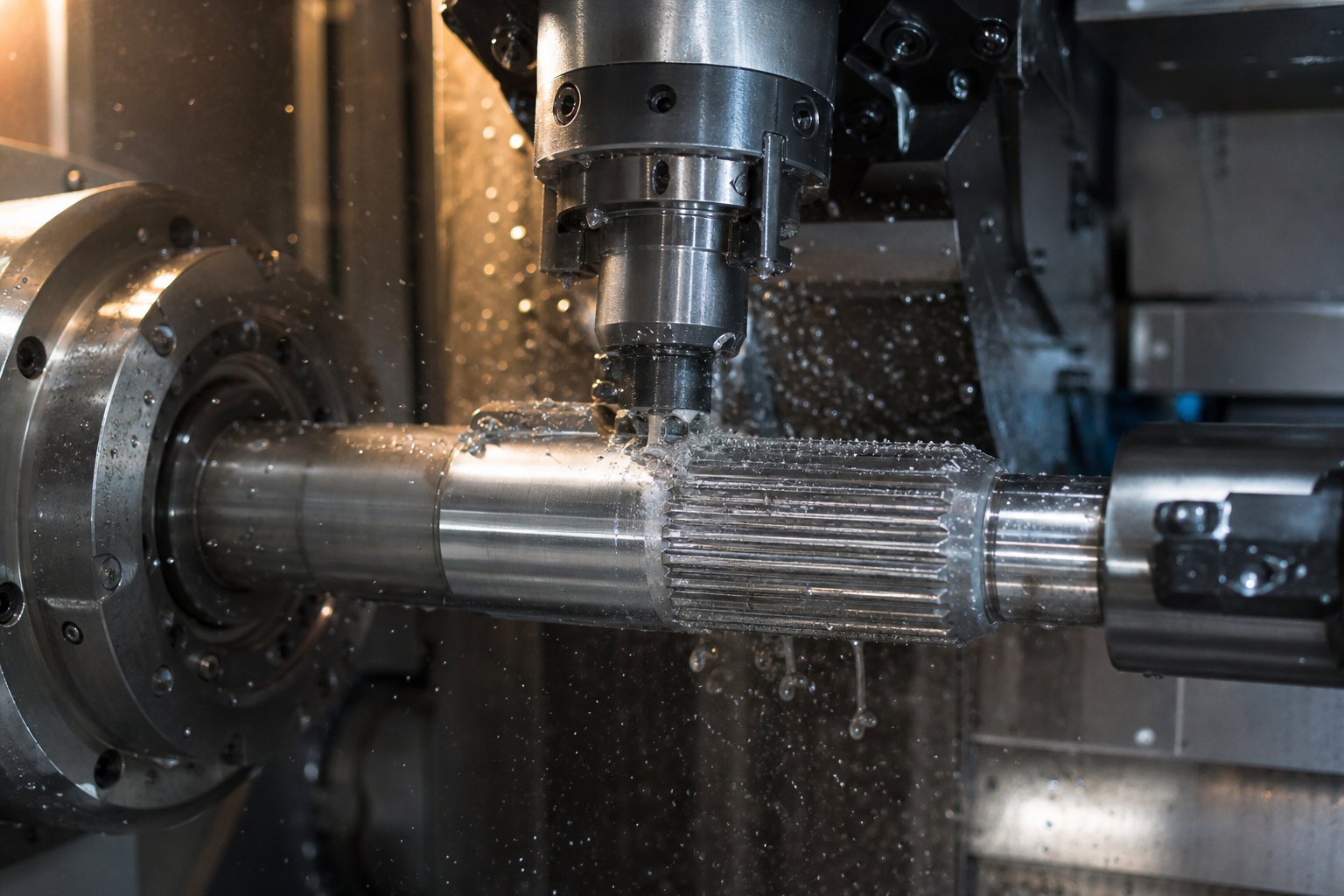
Two primary approaches dominate the production of splined extruder shafts: machining (milling, hobbing, or broaching) the spline profile from solid bar stock, and cold-forming (rolling) the profile through plastic deformation. Each method produces a functional spline, but the resulting mechanical properties, cost profiles, and application sweet spots differ substantially. Here's how they compare — and how to choose.
Milling — Machining Splines from Solid Bar Stock
Machining is the more intuitive process. You start with a round bar of heat-treated alloy steel and remove material until the spline profile emerges. In practice, this involves several possible cutting methods. Milling uses rotary cutters and is one of the most widely employed techniques for splined shafts. Hobbing — a specialized gear-cutting process using a helical cutting tool — offers high accuracy and is often the most cost-effective option for involute profiles. Broaching uses a multi-toothed linear tool to cut the entire profile in a single pass, delivering excellent dimensional precision.
All three share a fundamental characteristic: they create the spline by cutting away material. That distinction matters more than it might seem.
Pros
Profile flexibility. Machining can produce virtually any spline geometry — involute, straight-sided, asymmetric, or custom profiles unique to a specific OEM extruder model. If you need a non-standard tooth count, unusual pressure angle, or a profile that doesn't match existing rolling dies, machining is often the only practical option.
Small-batch economics. Setup costs for CNC hobbing or milling are relatively modest compared to the tooling investment required for cold rolling. When you need one replacement shaft or a short run of prototypes, machining almost always costs less per unit.
Material versatility. Machining works across the full range of extruder shaft materials — nitrided alloy steels, through-hardened tool steels, and stainless grades. Some high-alloy tool steels that would crack under cold-forming pressures machine without issue (though more slowly and with greater tool wear).
Cons
Grain flow disruption. This is the most significant mechanical limitation. When a cutting tool removes material to form a tooth, it severs the steel's natural grain flow lines at every cut surface. Those severed grain boundaries become potential crack initiation sites under cyclic loading — exactly the kind of loading a twin screw extruder shaft experiences continuously during operation.
Surface stress risers. Machined surfaces, even finely finished ones, contain microscopic tool marks, feed lines, and occasional burrs that act as stress concentrators. These features can seed fatigue cracks, particularly in the root area of the spline tooth where bending stress is highest.
Material waste. All the steel removed to create the spline profile becomes scrap. For large-diameter shafts with deep spline teeth, material utilization can be surprisingly poor.
Cold-Forming — Rolling the Spline Profile
Cold-forming takes a fundamentally different approach. Instead of cutting material away, hardened forming dies plastically deform the shaft surface into the spline shape. Imagine two rollers positioned above and below a rotating bar, striking the surface in precisely indexed increments to displace metal from the root area upward into the tooth tips. No material is removed — it's rearranged.
The process, as detailed by Gear Solutions, starts with bar stock that is rough-turned, straightened, and centerless-ground to an exact predetermined diameter between the root and outside diameter of the finished spline. Once in the rolling machine, forming rollers simultaneously strike the bar, displacing the negative shape of the spline into the surface. The bar indexes after each strike, and the rollers make contact again to form the next tooth and space. Feed rates vary depending on bar diameter, material hardness, and pitch.
The result is a spline with mechanical properties that machined profiles simply cannot match in several key areas.
Pros
Continuous grain flow. This is the headline advantage. Cold rolling rearranges the grain structure of the material over the entire tooth profile rather than cutting through it. As Gear Solutions reports, the displaced metal flows from the dedendum (root to pitch circle) upward to form the addendum (tooth tip), and the area of raw material displaced is exactly the same as the area from which it was displaced. The grain flow follows the contour of the spline tooth, producing dramatically increased strength — especially at the root area, where fatigue failure is most likely to initiate.
Work-hardened surface. The forming process itself hardens the spline surface through cold work, with the degree depending on material composition, initial hardness, tooth depth, and feed rate. In some applications, this work hardening can reduce or even eliminate the need for subsequent heat treatment. One example cited by industry case studies: a power tool manufacturer switched from hobbed-and-heat-treated gears to cold-rolled parts and found the parts performed so well without heat treating that they stopped lifecycle testing after four consecutive tests produced outstanding results.
Superior surface finish. Cold-formed splines achieve surface finishes as fine as Ra 4 — essentially a mirror finish. In load-bearing spline connections, smoother surfaces better support lubrication films and reduce the micro-welding and adhesive wear mechanisms that degrade spline fits over time.
No material waste. Since no metal is removed, material utilization approaches 100%. For expensive alloy steels, this can meaningfully reduce per-shaft material cost on volume production runs.
Cons
Tooling investment. Cold rolling requires precision-hardened forming dies specific to each spline profile. While die creation for new profiles can be accomplished quickly and at lower cost than many competing gear manufacturing methods, the initial tooling setup still represents a higher upfront investment than setting up a hobbing or milling operation.
Profile limitations. Cold rolling produces symmetrical patterns and works best with standard spline geometries. Highly custom or asymmetric profiles may not be feasible to roll. Additionally, the process works with materials up to approximately 20 Rockwell C hardness — meaning it must be performed before final heat treatment, which adds a sequencing constraint to the manufacturing workflow.
Material restrictions. Not all alloys respond equally well to plastic deformation. As cold-forming process documentation notes, some stainless steel and aluminum grades work-harden too quickly during rolling and cannot flow to fill in deep tooth forms. For twin screw extruder shafts made from certain high-alloy or stainless grades, cold forming may not be viable.
Choosing the Right Manufacturing Method
So how are twin screw extruder shafts made in practice? The answer depends on four interrelated factors: order volume, profile standardization, required mechanical performance, and budget constraints.
For a single replacement shaft with a custom or OEM-specific spline profile, machining is almost always the practical choice. The setup is straightforward, no special tooling is required, and a skilled CNC shop can work from drawings or a sample shaft. This is the typical scenario for maintenance teams ordering one or two replacement shafts for a specific extruder model.
For volume production of shafts with standard involute spline profiles — the kind an extruder OEM or a large-volume aftermarket supplier would produce — cold forming delivers superior fatigue life, better surface properties, and lower per-unit cost once tooling is amortized. The mechanical advantages of continuous grain flow and work-hardened surfaces are especially valuable in co-rotating twin screw applications where high cyclic torque loads make fatigue resistance the primary design concern.
Many production shafts actually combine both methods. A shaft might be cold-rolled for its primary spline profile to capture the fatigue and surface-finish benefits, then have secondary features — keyways, locating grooves, or custom end profiles — machined in a finishing operation. This hybrid approach captures the best of both worlds.
| Factor | Milling / Hobbing / Broaching | Cold-Forming (Rolling) |
|---|---|---|
| Process Description | Material removed by cutting tools to create spline profile from solid bar stock | Hardened dies plastically deform bar surface into spline shape; no material removed |
| Grain Structure | Severed at each machined surface — grain flow lines interrupted | Continuous grain flow follows spline tooth contour — grain structure rearranged, not cut |
| Surface Finish | Good (dependent on tool condition and feed rate); tool marks present at micro level | Excellent — as fine as Ra 4; smooth, burnished surface |
| Fatigue Resistance | Moderate — cut grain boundaries and surface stress risers reduce fatigue threshold | Superior — continuous grain flow and compressive work hardening significantly improve fatigue life |
| Surface Hardness | Determined entirely by material grade and subsequent heat treatment | Work-hardened during forming; may reduce or eliminate need for additional heat treatment |
| Cost (Small Batches: 1-5 Shafts) | Lower — minimal tooling investment, straightforward CNC setup | Higher — die costs must be amortized over very few parts |
| Cost (Large Batches: 50+ Shafts) | Higher per unit — each shaft requires full machining cycle time | Lower per unit — fast cycle times once tooling is set; no material waste |
| Profile Flexibility | High — any geometry, including custom and asymmetric profiles | Moderate — best suited to standard, symmetrical spline profiles |
| Material Compatibility | Broad — works with all extruder shaft materials including hardened tool steels and stainless alloys | Limited to materials below approximately 20 HRC before forming; some stainless grades may not be suitable |
| Best Application Scenario | Custom replacement shafts, prototype runs, OEM-specific profiles, stainless or tool steel shafts | Volume production of standard-profile shafts where fatigue life and surface quality are critical |
Here's the practical takeaway: when you're evaluating a replacement twin screw extruder shaft, ask your supplier how the splines were manufactured — not just what material was used. A cold-formed involute spline on a nitrided alloy steel shaft represents the gold standard for fatigue-critical, production-scale applications. A machined spline on the same material is perfectly adequate for many applications, especially when custom profiles or small quantities make cold forming impractical. The wrong choice isn't necessarily a failure waiting to happen, but it might mean the difference between a shaft that lasts five years and one that lasts ten.
Of course, even the best-manufactured shaft will eventually degrade if operational conditions push it beyond its design limits — or if subtle warning signs go unnoticed during routine maintenance. Recognizing how shafts fail, and catching problems before they become catastrophic, is where proactive maintenance separates high-uptime plants from those stuck in a cycle of reactive repairs.
Shaft Failure Modes and How to Prevent Them
A shaft doesn't fail out of nowhere. It sends signals — sometimes for weeks or months — before a catastrophic fracture shuts down your line. The challenge? Those signals are subtle, easy to miss during daily production, and often misattributed to other parts of the system. Understanding the specific ways a twin screw extruder shaft degrades turns reactive firefighting into proactive prevention, and it's the single highest-impact skill a maintenance team can develop.
Let's break down the primary twin screw extruder shaft failure causes, the inspection techniques that catch them early, and the operational practices that keep your shafts running years longer than they otherwise would.
Common Shaft Failure Modes and Their Root Causes
Every shaft failure falls into one of four broad categories. Recognizing which mode is developing — before it reaches the fracture stage — is what separates a planned repair from an emergency shutdown.
Torsional fatigue fracture is the most dramatic and destructive failure mode. It occurs when the shaft endures repeated cycles of high torsional loading that gradually initiate and propagate a crack through the cross-section. A failure analysis of a co-rotating twin screw extruder shaft confirmed that the combination of torsion and bending forces caused the shaft to fracture with clear evidence of fatigue progression. The crack didn't appear overnight. It grew incrementally — cycle after cycle — until the remaining cross-section could no longer carry the load, and the shaft snapped.
What drives torsional fatigue? Cyclic overloading from torque spikes is the primary culprit. Surging feed rates, jammed screw elements, cold starts without adequate barrel preheating, and running at throughput levels that consistently push the gearbox output near its torque limit all accelerate crack initiation. The spline root — where bending stress concentrates — is almost always where fatigue cracks begin, which is why spline profile quality and manufacturing method matter so much to long-term shaft life.
Spline wear is slower and less spectacular, but just as costly over time. Every screw element mounted on the shaft transfers torque through its spline connection. When that connection loosens — from contamination between mating surfaces, improper element fit, or cumulative micro-motion under load — the contact surfaces degrade progressively. You'll notice it first as a slight rattling sound during operation, then as difficulty removing elements during maintenance, and eventually as visible material loss on spline flanks. Abrasive wear from fillers, corrosive wear from reactive chemistries, and adhesive galling from metal-to-metal contact all accelerate the process. Once spline clearances open beyond tolerance, torque distribution becomes uneven across elements, and the shaft enters a self-reinforcing degradation cycle.
Corrosion-accelerated cracking affects shafts processing chemically aggressive materials. PVC releasing hydrochloric acid, moisture-laden food ingredients, and certain pharmaceutical compounds can pit the shaft surface and create localized stress concentrations. These pits act as crack initiation sites — combining the chemical attack with mechanical fatigue loading to produce failures at stress levels well below what the shaft was designed to handle. The nitrided case that protects standard alloy steel shafts can be undermined if corrosion penetrates through pinholes or scratches in the hardened layer.
Fretting damage at element-to-shaft interfaces is perhaps the most overlooked failure mechanism. It occurs when two tightly fitted surfaces experience tiny oscillating relative motion under load — not enough to qualify as sliding wear, but enough to generate oxide debris particles at the contact zone. These particles are harder than the parent metal, and they abrade the mating surfaces further, creating a progressively deepening damage zone. Fretting is insidious because it happens inside the connection, invisible to external inspection until it progresses to the point where elements wobble or the shaft surface shows visible discoloration when disassembled.
Inspection Techniques and Wear Indicators
Catching these failure modes early requires a structured inspection approach — not just a quick visual glance at the shaft during a screw pull. The following extruder shaft inspection checklist gives maintenance teams a prioritized workflow to follow during scheduled downtime:
- Visual surface inspection. With the shaft cleaned and screw elements removed, examine the entire spline surface under strong directional lighting. Look for surface pitting, discoloration (often a telltale blue or brown tint indicating localized overheating), corrosion spots, and any raised oxide debris at element seating locations — the hallmark of fretting damage.
- Dimensional measurement of spline wear. Use calibrated go/no-go spline gauges to check the effective tooth thickness at multiple positions along the shaft length. Compare readings against the original specification or baseline measurements from the last inspection. Pay special attention to the first few element positions nearest the gearbox, where torque loading is highest and wear accumulates fastest.
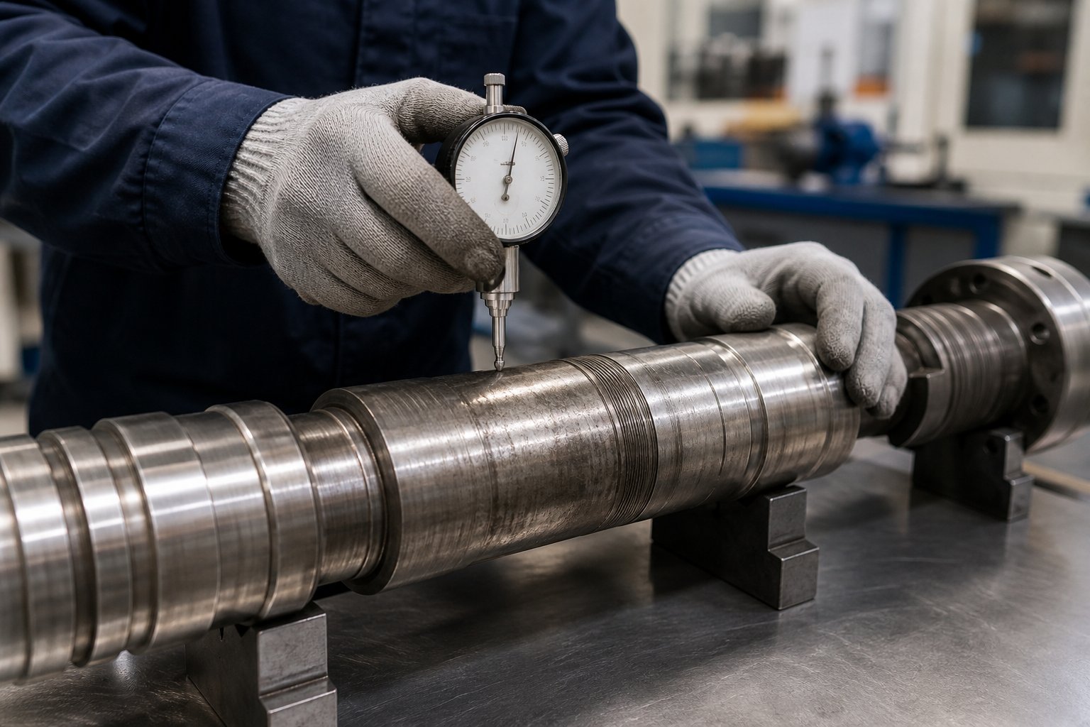
- Runout and straightness verification. Mount the shaft between centers and use a dial indicator to measure total indicated runout at several stations along its length. A shaft that has begun to deform under torsional fatigue loading will show increasing runout over successive inspections — a trend that predicts fracture well before a crack becomes visible.
- Non-destructive testing (NDT) for subsurface cracking. Magnetic particle inspection (MPI) is the most practical method for ferromagnetic extruder shaft materials. It reveals surface and near-surface cracks that are invisible to the naked eye, particularly in spline root areas where fatigue cracks initiate. For stainless steel shafts, dye penetrant testing serves the same purpose. Ultrasonic testing can detect deeper subsurface flaws but typically requires a trained NDT technician.
- Spline surface hardness spot-checks. Use a portable hardness tester to verify that the nitrided case is still intact at representative locations. A significant drop in surface hardness compared to baseline indicates that wear has progressed through the hardened layer into softer core material — a clear replacement trigger.
- Documentation and trend tracking. Record all measurements in a shaft-specific log. Single-point readings tell you where the shaft is right now; trend data over multiple inspection intervals tells you how fast it's getting there. As predictive maintenance frameworks emphasize, trend-based analysis catches developing failures weeks before absolute threshold alarms would trigger.
Preventive Strategies to Extend Shaft Life
Inspection catches problems that already exist. Prevention keeps them from developing in the first place. Here's how to prevent extruder shaft spline wear and delay the onset of fatigue — through operational discipline rather than expensive upgrades.
Most shaft failures trace back to operational practices rather than material defects. The shaft was strong enough for the job when it was installed. What changed was how the machine was run.
Follow proper screw element torquing sequences. When assembling elements onto the shaft, torque the tip bolt or locking mechanism to the OEM-specified value — not tighter. Over-torquing compresses elements against each other and creates stress concentrations at the element-to-shaft interface. Under-torquing allows micro-movement that initiates fretting. Use a calibrated torque wrench, not an impact driver, and apply torque in the sequence recommended by the extruder manufacturer.
Verify element-to-shaft clearances during every assembly. Screw elements that slide on too easily have excessive spline clearance. Elements that require force to seat may indicate shaft spline damage or burrs. Either condition leads to uneven torque distribution and accelerated wear. Keep a reference set of new elements on hand for comparison, and reject any element-shaft pairing where fit has noticeably changed from baseline.
Monitor gearbox alignment continuously. A misaligned gearbox output shaft imposes bending loads on the extruder shaft that it was never designed to carry. Those bending loads combine with normal torsional loading to amplify the stress at the most vulnerable point — the spline root at the drive end. The failure analysis case study mentioned earlier specifically identified the combination of torsion and bending as the root cause of fatigue fracture. Periodic alignment checks using dial indicators or laser alignment tools are among the highest-value preventive activities a maintenance team can perform.
Control barrel temperatures to prevent thermal shock. Rapid temperature changes — especially cold starts where material is forced through a barrel that hasn't reached operating temperature — generate massive torque spikes as the screws try to push solid or semi-molten polymer. These spikes can exceed the shaft's fatigue threshold even if they're brief. Always follow a gradual heat-up procedure, and never start screw rotation until all barrel zones have stabilized within their target range.
Manage feed rates to avoid torque spikes. Flood feeding or inconsistent feeder output creates surges of material in the extruder that translate directly into torsional load spikes on the shaft. Starve feeding with a gravimetric or volumetric feeder — the standard approach for twin screw extrusion — provides much smoother torque profiles. Monitor motor current draw as a real-time proxy for shaft torque; motor current signature analysis can reveal bearing degradation and abnormal loading patterns weeks before operators would notice any change in machine behavior.
Implement a predictive monitoring baseline. You don't need a six-figure analytics platform to start. Record motor current, melt pressure stability, and vibration readings during stable operation to establish a "normal fingerprint" for your machine. When those readings start drifting — current trending upward, pressure oscillations becoming more erratic, vibration amplitude increasing — something mechanical is changing. Acting on those trends during planned downtime, rather than waiting for audible symptoms, is the difference between a bearing swap and a full shaft replacement.
Torsional fatigue fracture extruder shaft prevention ultimately comes down to respecting the shaft's design limits and watching for the earliest signs that those limits are being approached. The shafts themselves are robust, precision-engineered components. The failures almost always start with something the operations team can control — a torque spike that shouldn't have happened, a temperature ramp that was skipped, a spline fit that was accepted when it shouldn't have been. Fix the practices, and the shaft takes care of itself.
Even with the best preventive program, though, every shaft eventually reaches a point where wear accumulates beyond what inspection can clear. When that happens, the decision shifts from "how do I keep this shaft running" to "what shaft do I need, and how do I get the right one" — a specification-matching challenge that depends heavily on knowing your extruder's exact size class and model configuration.
Matching Shaft Specifications to Extruder Size and Model
You've identified the wear, confirmed the failure mode, and decided your shaft needs replacing. Now comes the question that trips up even experienced procurement teams: what exact shaft do you actually need? Getting the material grade right matters. Getting the spline profile right matters. But none of it helps if the replacement shaft doesn't physically match your machine's geometry, torque rating, and element compatibility.
Twin screw extruder shaft specifications vary dramatically across machine sizes, and a shaft designed for a lab-scale 18 mm extruder has almost nothing in common with one built for a 135 mm production machine — other than the basic engineering principles covered in earlier sections. Understanding how shaft requirements scale with extruder size class gives you a reliable framework for ordering replacements, whether you're working from OEM documentation or reverse-engineering a worn sample.
Lab-Scale and Pilot Extruder Shafts
Small extruders — typically those in the lower diameter ranges used for R&D formulation development, small-batch pharmaceutical processing, or university research — place a very different set of demands on their shafts compared to production machines.
Torque loads are modest. Throughput rates might range from a few grams per minute to single-digit kilograms per hour. The shafts are physically small, with fewer spline teeth and proportionally simpler connection methods. You'll frequently encounter hexagonal bore connections or straight splines on these machines rather than the involute profiles that dominate larger extruders. Why? Because at these small diameters, the torque density challenge discussed earlier is less severe — and the practical priority shifts toward easy element changeover during frequent screw configuration trials.
Material selection often differs too. Lab-scale extruders may use stainless steel shafts even for standard polymer work, not because corrosion resistance is critical, but because smaller batch sizes and more frequent cleaning cycles make stainless a practical choice. Leistritz's technical documentation notes that small extruders can be specified with low-volume screws and specialty feed mechanisms for micro-batch sampling — sometimes processing as little as 50 grams. At these scales, the shaft's role as a precision alignment tool matters as much as its torque-carrying capacity.
The flip side? Replacement shafts for lab-scale machines can be surprisingly difficult to source. Production volumes are low, OEM inventories are thin, and the small physical dimensions demand tight manufacturing tolerances despite the modest loads. If your lab extruder is from a niche manufacturer, you may need a supplier who can work from a sample shaft or detailed drawings rather than a catalog part number.
Production-Scale Extruder Shaft Specifications
Step up to mid-range and large production extruders — the workhorses running compounding, masterbatch, and direct extrusion operations at hundreds or thousands of kilograms per hour — and the shaft engineering challenge intensifies on every front.
These machines demand involute spline profiles capable of transmitting high torque densities through the constrained diameters imposed by close center-to-center shaft spacing. Spline tooth counts increase with shaft diameter to spread the torque load across more contact surfaces, and the scaling relationship between these parameters is carefully engineered by each OEM to maximize torque capacity within their specific barrel geometry.
The screw shaft rating — denoted in Newton-meters — becomes a critical specification at production scale. As Leistritz's twin screw technical reporting explains, the design factors that determine this rating include cross-sectional area, shaft metallurgy, spline geometry, and the hardening process. State-of-the-art production extruders use asymmetrically splined shafts that direct a tangential force vector into the screws, extracting maximum torque from the available shaft cross-section. A torque-limited process — common when processing high-viscosity materials like fractional melt HDPE or PP — will hit its throughput ceiling at the shaft's Newton-meter rating before any other boundary condition intervenes.
Advanced material treatments become non-negotiable at this scale. Nitrided alloy steel with precisely controlled case depth is the standard baseline. Through-hardened tool steels enter the picture for heavily filled compounds or glass-fiber-reinforced formulations. The relationship between extruder shaft dimensions and spline count, shaft length, and torque capacity is OEM-specific — meaning a replacement shaft must match not just the general size class but the exact dimensional envelope of the original design.
This is where general knowledge of scaling principles meets the hard reality of machine-specific engineering: two 60 mm twin screw extruders from different manufacturers can have completely different shaft lengths, spline tooth counts, and torque ratings, even though they share the same nominal screw diameter.
Matching Shafts to OEM Extruder Models
So how do you identify the exact twin screw extruder shaft specifications by model when it's time to order a replacement? Start with what you can document directly from the machine itself, then fill gaps using OEM resources and supplier expertise.
Read the nameplate data. Every extruder has a nameplate — typically on the gearbox housing or barrel assembly — listing the manufacturer, model designation, serial number, and key specifications. The model number alone often encodes the screw diameter and sometimes the OD/ID ratio or torque class. For example, a designation like "ZSE 60 MAXX" tells you it's a 60 mm co-rotating extruder in a specific high-torque series. That model code gives any knowledgeable supplier a starting point for identifying the correct shaft configuration.
Consult OEM documentation. Original equipment manuals, spare parts lists, and engineering drawings are the gold standard. They'll specify shaft dimensions, spline profile details (tooth count, module, pressure angle), material grade, heat treatment requirements, and critical tolerances. If you've lost your documentation, contact the OEM's service department — many maintain digital archives accessible by serial number.
Measure the existing shaft. When OEM documentation isn't available — common with older machines, discontinued models, or equipment purchased secondhand — direct measurement of the worn shaft becomes your primary specification source. A skilled machinist or metrology lab can capture all critical dimensions: overall length, spline outside diameter, root diameter, tooth count, tooth thickness, and bore dimensions. Even a worn shaft carries enough dimensional information to reverse-engineer a replacement within tolerance, provided the wear hasn't advanced to the point of obliterating original geometry.
Work with aftermarket suppliers who reverse-engineer from samples. Brands like CPM Century and other major OEMs have proprietary shaft configurations that aren't published in open catalogs. Aftermarket manufacturers specializing in extruder components can replicate these designs by working from drawings, dimensional data, or physical samples. This OEM twin screw extruder shaft matching guide approach is particularly valuable when original shafts are backordered, discontinued, or priced at a premium with long lead times.
When you're ready to order, make sure you have these essential data points documented and confirmed before contacting any supplier:
- Overall shaft length — measured end to end, including any stepped sections or reduced-diameter drive ends
- Spline profile type — involute (with module and pressure angle), straight-sided, or hexagonal
- Number of spline teeth — counted directly from the shaft or taken from OEM specifications
- Spline outer diameter (OD) — the major diameter measured across the tooth tips
- Inner bore dimensions — if the shaft has a hollow bore or internal coolant passage
- Material grade — the specific steel alloy designation, not just a generic category
- Heat treatment specification — nitriding depth, through-hardening parameters, or surface treatment requirements
Missing even one of these data points can result in a replacement shaft that looks right but doesn't fit, doesn't carry the required torque, or wears prematurely because the surface treatment doesn't match the application demands. Take the time to get the specification right before placing the order — it's far cheaper than dealing with a shaft that arrives and doesn't work.
Getting the specification nailed down answers the "what" question. But there's a parallel decision that many maintenance teams face before they ever place that order: is the existing shaft truly beyond recovery, or could reconditioning restore it to serviceable condition at a fraction of the replacement cost? That repair-versus-replace decision has its own set of engineering criteria — and getting it wrong in either direction costs real money.
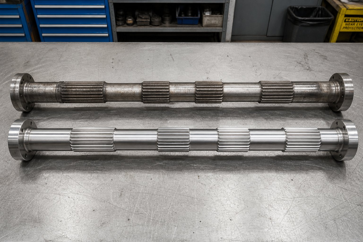
Shaft Reconditioning vs. Full Replacement Decisions
A worn twin screw extruder shaft doesn't always mean a purchase order for a brand-new one. In many cases, reconditioning can restore the shaft to serviceable condition at a fraction of the cost — buying you months or even years of additional production life. But reconditioning the wrong shaft wastes money and creates a false sense of security. The real skill is knowing which side of that line your shaft falls on.
Let's walk through the twin screw extruder shaft reconditioning options available, the hard boundaries where reconditioning stops being viable, and a practical decision framework for choosing between extruder shaft repair vs replacement cost paths.
When Shaft Reconditioning Is Viable
Imagine pulling a shaft during a scheduled shutdown and finding moderate spline wear, minor surface corrosion on a few element positions, or localized scoring from a contamination event. The shaft isn't pristine — but is it finished? Not necessarily.
Three reconditioning approaches cover the majority of recoverable shaft damage:
Re-splining involves machining new spline surfaces onto the existing shaft body. If wear has reduced tooth thickness beyond tolerance but the shaft's core diameter and overall geometry remain sound, a skilled machinist can cut the spline profile to a slightly smaller pitch diameter and restore proper tooth form. The shaft then mates with correspondingly re-bored or new screw elements. This approach works best when wear is uniform along the shaft length and the remaining material provides adequate cross-sectional area for the required torque load.
Re-nitriding reapplies the surface hardening treatment after light machining or polishing has removed the degraded outer layer. Since nitriding is a diffusion process performed at relatively low temperatures, it introduces minimal distortion — making it well-suited for re-treating a shaft that's already been finish-machined. The key requirement is that enough core material remains above the minimum diameter to accept a new nitrided case of adequate depth.
Weld buildup with re-machining addresses localized damage — a corroded zone, a worn bearing seat, or a damaged section where an element was galled onto the spline. Material is deposited using controlled welding techniques, then machined back to the original dimensional specification. As shaft repair welding specialists emphasize, this process demands careful attention to metallurgy: the base material must be identified, preheating is essential for medium-carbon and alloy steels to prevent brittle martensite formation, and post-weld heat treatment is critical for restoring ductility in the heat-affected zone. Done incorrectly, a weld repair can introduce fatigue crack initiation sites that are worse than the original damage.
Viability ultimately depends on three factors: the extent of wear relative to the shaft's original dimensions, the integrity of the core material as confirmed by non-destructive testing, and whether original tolerances can be restored within the limits that your screw elements require for proper fit.
When Full Replacement Is Necessary
Some conditions make reconditioning impractical — or outright dangerous. Knowing when to replace a twin screw extruder shaft rather than repair it prevents you from sinking reconditioning costs into a shaft that will fail again shortly after reinstallation.
Fatigue cracking detected by NDT is the clearest replacement trigger. Magnetic particle inspection or ultrasonic testing that reveals cracks — particularly in spline root areas or at diameter transitions — means the shaft's structural integrity is already compromised. As gear shaft testing research confirms, even small cracks in high-stress zones like bearing seats, shoulders, and keyways are common starting points for fatigue failure. Welding over a fatigue crack doesn't remove the damage — it just buries it under new material while residual stresses from the repair accelerate propagation.
Excessive diameter reduction beyond re-machinable limits is the second hard stop. Every re-splining operation removes material, reducing the shaft's effective cross-section. Once the remaining diameter drops below the minimum needed to carry the extruder's rated torque, no surface treatment can compensate for the lost structural capacity.
Severe corrosion penetrating beyond the nitrided case compromises the core alloy's mechanical properties. Surface reconditioning can't restore grain structure that's been chemically degraded at depth. Similarly, torsional deformation — a shaft that's permanently twisted under overload — indicates the core material has yielded plastically. A deformed shaft cannot be straightened reliably enough to maintain the precise spline alignment that twin screw element stacking requires.
Cost-Benefit Analysis of Reconditioning vs. Replacement
The financial comparison isn't as straightforward as "reconditioning costs less." It often does — sometimes significantly so — but several factors complicate the math.
Reconditioning cost typically runs a fraction of new shaft procurement, especially for large-diameter production shafts where raw material and precision machining represent substantial expenses. However, reconditioning also carries turnaround time: the shaft must be removed, shipped to a repair facility, evaluated, processed, and returned. If your extruder can't run during that window and you don't have a spare shaft on hand, the production loss may dwarf the savings on the repair itself.
Remaining service life is the other variable. A reconditioned shaft may deliver 60-80% of a new shaft's expected life — or significantly less, depending on the extent of original damage and the reconditioning method used. If the shaft was already near the end of its fatigue life when it was pulled, re-splining and re-nitriding buy you time but don't reset the clock on cumulative fatigue damage in the core material.
Replacement shaft availability has changed the equation in recent years. Aftermarket suppliers who can manufacture shafts from drawings or reverse-engineer from samples have shortened lead times and reduced costs compared to OEM-only sourcing channels. For example, manufacturers like NANHAIYA can produce custom replacement shafts and screw-related components from technical drawings or physical samples, giving maintenance teams a viable path to new-shaft procurement without the premium pricing or extended lead times sometimes associated with original equipment channels.
Here's a practical decision framework to guide the repair-vs-replace call:
| Decision Factor | Favors Reconditioning | Favors Replacement |
|---|---|---|
| NDT Results | No cracks detected; surface damage only | Any fatigue cracking in spline roots or transitions |
| Dimensional Wear | Within re-machinable limits; adequate core diameter remains | Diameter reduced beyond minimum torque-carrying threshold |
| Corrosion Depth | Surface-level only; nitrided case partially intact | Penetration into core material beyond case depth |
| Shaft Straightness | Runout within correctable range | Permanent torsional deformation or excessive runout |
| Budget Priority | Immediate cost reduction is critical; production loss during turnaround is manageable | Long-term reliability and maximum service life justify higher upfront investment |
| Spare Shaft Availability | No spare on hand; reconditioning turnaround is shorter than new shaft lead time | Replacement available from OEM or aftermarket supplier within acceptable lead time |
| Previous Reconditioning History | First reconditioning cycle; shaft has not been previously re-splined | Shaft has already been reconditioned once or more; cumulative fatigue risk is elevated |
The smartest maintenance teams don't wait until a shaft fails to make this decision. They track inspection data over time, establish wear thresholds that trigger a reconditioning evaluation, and keep sourcing relationships in place so a replacement can be ordered before the situation becomes an emergency. That kind of proactive lifecycle management — integrating inspection, reconditioning, replacement sourcing, and spare parts strategy into a single coherent plan — is what separates plants that control their downtime from those that react to it.
Sourcing Strategy and Shaft Lifecycle Management
Reactive maintenance is expensive. A shaft that fails during a production run doesn't just cost you the price of a replacement part — it costs you the lost production hours, the emergency freight charges, the overtime labor for an unplanned teardown, and sometimes the scrapped material sitting in the barrel when everything stopped. Multiply that across even one or two unplanned failures per year, and the total easily exceeds what a structured twin screw extruder shaft replacement sourcing and lifecycle management program would have cost to implement.
Everything covered in this article — spline geometry, material selection, manufacturing methods, failure modes, inspection techniques, reconditioning criteria — converges on a single practical objective: keeping your extruder running by managing shaft condition proactively rather than reacting to breakdowns. Here's how to put that knowledge into an actionable extruder shaft lifecycle management strategy.
Building a Shaft Maintenance and Replacement Strategy
Think of shaft lifecycle management as a continuous loop rather than a one-time event. It starts the moment a new or reconditioned shaft is installed and doesn't end until the replacement is already on order — ideally well before the current shaft reaches its wear limits.
The plants that achieve the highest uptime don't rely on institutional memory or tribal knowledge passed between shift supervisors. They document, schedule, measure, and plan. The following checklist captures the core elements of a lifecycle approach that any maintenance organization can implement:
- Document baseline specifications at installation. Record the shaft's material grade, heat treatment details, spline profile type and dimensions, OEM part number or drawing reference, supplier, and installation date. Take baseline dimensional measurements — spline tooth thickness, runout, and surface hardness — before the shaft ever runs. These become your reference points for every future inspection.
- Establish scheduled inspection intervals. Align shaft inspections with your existing preventive maintenance calendar. A practical starting point: visual and dimensional checks every 2,000-4,000 operating hours, with full NDT evaluation annually or during major shutdowns. Adjust frequency based on process severity — abrasive fillers, corrosive chemistries, or consistently high torque utilization all justify shorter intervals.
- Define wear threshold triggers. Set clear, measurable criteria that move the shaft from "monitor" to "plan reconditioning" to "order replacement." Spline tooth thickness reduced by a defined percentage from baseline, surface hardness dropping below a threshold value, or runout exceeding a specific limit should each trigger a documented action — not a conversation that gets deferred to the next meeting.
- Track trends, not just snapshots. A single measurement tells you where the shaft is today. A series of measurements over successive inspection intervals tells you how fast it's getting there. Plotting spline wear rate over time lets you project when the shaft will reach its replacement threshold — and place orders accordingly, months before the situation becomes urgent.
- Maintain supplier relationships before you need them. The worst time to evaluate a new replacement extruder shaft supplier selection criteria is during an emergency. Identify and qualify at least one aftermarket source capable of manufacturing to your specifications, confirm their lead times and material capabilities, and keep your shaft drawings or sample dimensions on file with them. When you do need to order, the process takes days instead of weeks.
- Stock critical spares strategically. For production-critical extruders where any unplanned downtime carries significant financial impact, keeping a spare shaft on the shelf eliminates the lead-time variable entirely. The carrying cost of a spare shaft is trivial compared to a week of lost production waiting for one to be manufactured and shipped.
This isn't a complex system. It's a disciplined one. The difference between plants that manage shaft life proactively and those that don't isn't budget or technology — it's whether someone owns the process and follows through consistently.
Sourcing Replacement Shafts and Extruder Spare Parts
When the decision shifts from "maintain" to "replace," how to evaluate an extruder spare parts supplier becomes a critical competency. Not all suppliers are equal, and the wrong choice — whether it's a shaft that doesn't match your spline tolerances or a material grade that underperforms your process demands — creates problems that outlast whatever savings prompted the decision.
Here's what matters most when vetting a supplier for replacement twin screw extruder shafts and related components:
- Custom manufacturing from drawings or samples. Suppliers like NANHAIYA offer the capability to produce replacement shafts and extruder spare parts from technical drawings or physical samples — directly addressing the OEM-matching challenge that makes shaft sourcing difficult. Their catalog spans screw-related components, barrel segments, heater bands, thermocouples, die heads, and pelletizing blades, making them a single-source option for comprehensive extruder rebuilds rather than piecemeal procurement across multiple vendors.
- Material certifications and traceability. Any credible supplier should provide mill certificates documenting the chemical composition and mechanical properties of the steel used in your shaft. As the due diligence frameworks for sourcing from China emphasize, insisting on material test certificates for every batch of steel is non-negotiable — the foundation of any durable extruder component is verified raw material.
- Heat treatment capabilities and documentation. The supplier must demonstrate mastery of the specific surface treatment your shaft requires — whether that's gas nitriding, plasma nitriding, or through-hardening. Request metallographic reports and hardness test results from previous production batches. A supplier who can't provide these has no way to prove that their heat treatment process consistently delivers the case depth and surface hardness your application demands.
- Dimensional inspection and quality documentation. Verify that the supplier uses calibrated inspection equipment — coordinate measuring machines (CMMs), spline gauges, surface profilometers — and provides detailed inspection reports with each shipment. For high-value components like extruder shafts, consider engaging a third-party pre-shipment inspection through organizations like SGS or TUV, particularly for first orders with a new supplier.
- OEM compatibility and reverse-engineering track record. Ask specifically about experience producing parts for your extruder brand and model. A supplier who has previously manufactured shafts compatible with CPM Century, Coperion, Leistritz, JSW, or other major OEM platforms brings practical knowledge of those proprietary configurations that reduces the risk of specification errors.
- Lead time transparency and logistics capability. Understand the supplier's realistic production timeline — from order confirmation through material procurement, machining, heat treatment, inspection, and shipping. Suppliers with export experience will also handle proper anti-rust packaging and container loading procedures that protect precision components during ocean freight.
One sourcing principle deserves special emphasis: don't optimize solely for the lowest unit price. A shaft that costs 15% less but fails 40% sooner delivers negative value. The real metric is cost per operating hour — and that calculation favors suppliers who demonstrate material quality, manufacturing precision, and process control over those who compete primarily on price.
For maintenance teams managing multiple extruders or planning a comprehensive rebuild, consolidating spare parts procurement through a single supplier who covers shafts, screw elements, barrel segments, and auxiliary components simplifies logistics, reduces shipping costs, and ensures dimensional compatibility across all replaced parts. That integrated approach — one supplier, one quality standard, one point of accountability — consistently outperforms the fragmented purchasing model where each component comes from a different source.
The twin screw extruder shaft sits at the intersection of every topic this article has covered: precision engineering, material science, manufacturing technology, failure analysis, and practical maintenance strategy. It's a component that rarely gets the attention it deserves — until it fails and everything stops. The plants that treat shaft management as a continuous discipline rather than an emergency response don't just avoid downtime. They extract more throughput, more consistency, and more years of service from the same equipment. That's the fix — not a single action, but a system that never lets the shaft become the weakest link in your extrusion process.
Frequently Asked Questions About Twin Screw Extruder Shafts
1. What is the difference between a twin screw extruder shaft and the screw elements?
The shaft is the permanent, load-bearing steel backbone that runs the full length of the processing section. It transfers rotational torque from the gearbox via splined connections. Screw elements — conveying elements, kneading blocks, and mixing discs — are modular, interchangeable parts that slide onto the shaft's splined surface. When ordering replacements, confusing the two leads to costly specification errors. Suppliers like NANHAIYA (nhyscrews.com) can produce both shafts and screw-related components from drawings or samples, helping maintenance teams avoid mismatches.
2. What causes a twin screw extruder shaft to fail prematurely?
The most common causes are torsional fatigue fracture from repeated torque spikes, spline wear from improper element fit or contamination, corrosion-accelerated cracking in chemically aggressive environments, and fretting damage at element-to-shaft interfaces. Most failures trace back to operational practices rather than material defects — including cold starts without adequate barrel preheating, flood feeding that creates torque surges, over-torquing or under-torquing screw element tip bolts, and neglecting gearbox alignment checks. A structured inspection program using go/no-go spline gauges and NDT methods catches these issues before they become catastrophic.
3. How do I choose the right material for a replacement twin screw extruder shaft?
Material selection depends on your process chemistry, torque demands, and budget. Nitrided alloy steel is the industry standard for general polymer compounding — it offers excellent fatigue resistance and surface hardness at a moderate cost. Through-hardened tool steel suits extreme applications like heavily filled masterbatch or glass-fiber-reinforced compounds where high bulk hardness throughout the cross-section is essential. Martensitic stainless steel (such as 440C) is required for food, pharmaceutical, or PVC processing where corrosion resistance is non-negotiable. Each category involves trade-offs between toughness, cost, and wear performance.
4. Can a worn twin screw extruder shaft be reconditioned instead of replaced?
Yes, if the damage is limited to moderate spline wear, minor surface corrosion, or localized scoring. Common reconditioning methods include re-splining (machining new spline surfaces), re-nitriding (reapplying surface hardening), and weld buildup with re-machining for localized damage. However, replacement is necessary when NDT detects fatigue cracking, diameter reduction exceeds re-machinable limits, corrosion has penetrated beyond the nitrided case, or the shaft shows permanent torsional deformation. For cost-effective replacements, aftermarket manufacturers like NANHAIYA can produce custom shafts from drawings or samples with shorter lead times than many OEM channels.
5. What information do I need to order a replacement twin screw extruder shaft?
You need seven key data points: overall shaft length (including stepped sections), spline profile type (involute with module and pressure angle, straight-sided, or hexagonal), number of spline teeth, spline outer diameter measured across tooth tips, inner bore dimensions if the shaft is hollow, the specific material grade designation, and heat treatment specification including nitriding depth or through-hardening parameters. This information can be gathered from OEM documentation, machine nameplates, or direct measurement of the existing shaft. Aftermarket suppliers experienced with major OEM platforms can also reverse-engineer specifications from physical samples.
Written by
Nanhaiya Technical Team
Zhoushan Nanhaiya Plastic Machinery Co., Ltd.
The Nanhaiya technical team supports screw and barrel manufacturing projects through application review, technical communication, custom manufacturing coordination, and production and quality control.
Discuss Your Application
Related Articles
More insights on screw barrel technology and plastics processing.

What Nobody Tells You About Screw Barrel For Plastic Machine Design
Oct 10, 2026
Learn how screw barrel for plastic machine design affects melt quality, throughput, and wear life. Covers geometry, resin matching, troubleshooting, and sourcing.
Read Article
Single Screw Extruder for Sheet: Stop Guessing, Start Specifying
Oct 9, 2026
Learn how to specify a single screw extruder for sheet production. Covers screw geometry, resin-specific processing, troubleshooting, and maintenance best practices.
Read Article
PE Pipe Extruder Machine: What Datasheets Won't Tell You
Oct 9, 2026
Learn how a PE pipe extruder machine works, key specs explained, material grade selection, maintenance tips, and buyer guidance beyond the datasheet.
Read ArticleLooking for something else?
Search by material, symptom or product and jump straight to the relevant page.
These are navigation suggestions based on keyword matching — not a quotation, not a delivery commitment, and not a substitute for engineering review. Final specification is confirmed by our engineers against your drawings and processed material.
Need help with screw barrel selection?
Share your machine model, processed material and application. Our team can help with pricing and technical support.