

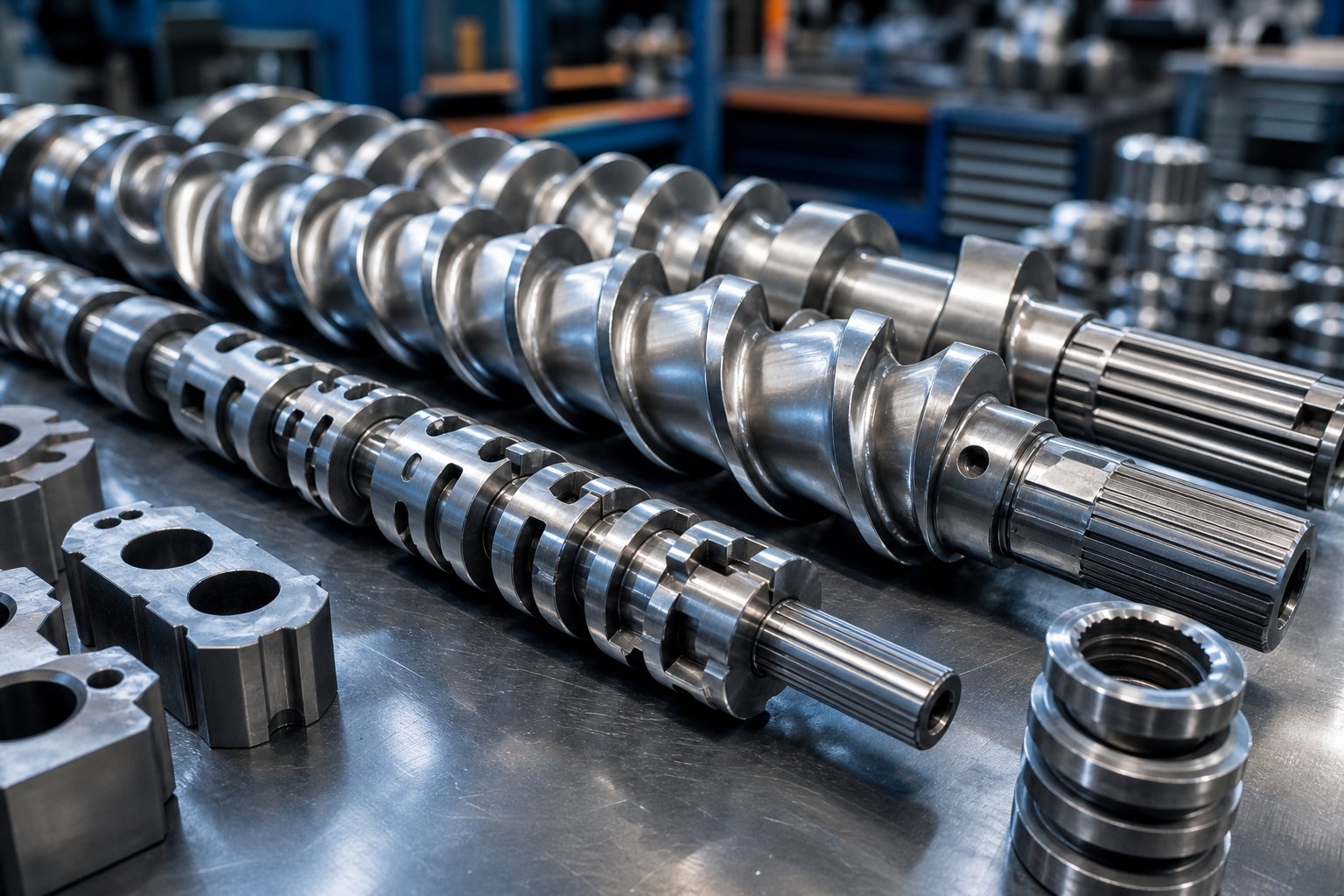
What Twin Screw Extruder Screw Elements Are and Why They Matter
Imagine being able to redesign the heart of your extruder in a matter of hours — without buying a new machine. That is exactly what twin screw extruder screw elements make possible.
What Are Twin Screw Extruder Screw Elements
Twin screw extruder screw elements are modular, interchangeable components that slide onto splined shafts inside the extruder barrel. Each element performs a specific job — conveying raw material forward, melting and shearing polymer, mixing in additives, or building the pressure needed to push melt through a die. By rearranging these segments along the shaft, engineers construct a complete screw profile tailored to a particular material and process.
Every element falls into one of three broad functional categories:
- Conveying elements — helical-flighted segments that transport material downstream and control fill level.
- Mixing elements — kneading blocks and specialized discs that apply shear, disperse fillers, and homogenize the melt.
- Sealing and restricting elements — reverse-flighted segments and blister rings that create pressure dams, melt seals, and residence time control points.
This segmented architecture is the defining advantage of twin screw machines over traditional single screw extruders. A single screw extruder uses a one-piece screw machined for a fixed application — change the material or formulation, and you may need an entirely new screw. A modular extruder screw, by contrast, lets operators swap individual elements to shift from gentle distributive blending to aggressive dispersive mixing without any permanent hardware commitment.
Why Screw Element Selection Matters for Processing Outcomes
So what does the screw do, practically speaking, when you change its element lineup? It alters four measurable outcomes that define product quality and process economics:
- Specific mechanical energy (SME) — the energy per unit mass transferred from the motor through the extrusion screw into the compound. A Dow case study showed that matching SME across extruder scales — for instance, targeting roughly 0.08 kWh/kg — was essential for consistent masterbatch quality.
- Melt temperature rise — directly tied to shear intensity in kneading blocks and narrow-gap elements.
- Residence time distribution — governed by the number and placement of restrictive or reverse elements along the barrel.
- Degree of fill — controlled by pitch, flight depth, and the balance between conveying capacity and feed rate.
In short, screw design is not an afterthought — it is the single most impactful lever in process optimization. The sections ahead walk through this decision layer by layer, from fundamental geometry parameters to complete zone-by-zone profile construction, mirroring the way experienced engineers actually approach an extruder screw build.

Screw Element Geometry Parameters That Control Performance
Every processing outcome discussed above — energy input, melt temperature, residence time, and fill level — traces back to a handful of measurable geometry variables built into each element. Change one dimension by even a few millimeters, and the material experiences a noticeably different shear history, dwell time, and pressure profile. Understanding these parameters is the foundation of effective screw design, so let's break each one down.
Pitch, Lead, and Flight Depth Explained
Pitch is the axial distance measured along the screw from one flight crest to the next crest of the same flight. Think of it as the spacing between the "threads" on the element. In standard screw extrusion nomenclature, a tighter pitch means the flights are packed closer together, while a wider pitch spreads them apart.
Lead is the axial distance the material advances for one complete rotation of the shaft. For single-flight elements, lead equals pitch. For double-flight (bi-lobed) elements — the most common configuration in co-rotating machines — the lead is twice the pitch. This distinction matters because increasing the pitch directly increases shear input into the raw material, while simultaneously changing the volume available in each channel for material transport.
Flight depth (also called channel depth) is the radial distance from the screw root up to the tip of the flight. Deeper flights create a larger channel cross-section, allowing more material volume per unit length. Decreasing either channel depth or channel width increases the shear experienced by the material because the polymer is forced through a narrower gap.
Here is the practical tradeoff you'll encounter repeatedly:
- Wider pitch + deeper flights — higher throughput capacity, faster conveying, lower shear, and shorter residence time. Ideal for feed zones where the goal is rapid material intake.
- Narrower pitch + shallower flights — reduced free volume, higher degree of fill at a given feed rate, increased local pressure, and greater shear. Useful in metering zones where stable pressure buildup is the priority.
The OD/ID ratio (outer diameter to inner diameter) ties these variables together into a single design parameter. The outer diameter (OD) is the circle traced by the flight tips, while the inner diameter (ID) is the circle at the screw root. A higher OD/ID ratio means deeper channels and more available volume per revolution, but it also means a thinner shaft core, which limits torque capacity. A lower OD/ID ratio produces shallower channels, higher shear rates in the flight-tip-to-barrel-wall gap, and a more robust shaft — at the cost of reduced throughput volume. Most co-rotating twin screw extruders use OD/ID ratios between 1.22 and 1.71, with higher ratios favoring high-volume, low-shear applications and lower ratios suiting high-torque, shear-intensive compounding.
Stagger Angle, Number of Tips, and Lobe Geometry
When you move from conveying elements to kneading blocks, a new parameter takes center stage: the stagger angle. This is the angular offset between adjacent disc elements within a kneading block assembly. Common stagger angles are 30°, 45°, 60°, and 90°, and each one dramatically shifts the balance between conveying action and mixing intensity.
Imagine stacking several oval-shaped discs on a shaft. If each disc is rotated only 30° relative to its neighbor, the resulting block still pushes material forward — almost like a coarse-threaded conveying element. Increase that offset to 90°, and the forward-pumping effect vanishes entirely. The material stalls, residence time spikes, and shear forces intensify. Research from Paderborn University confirmed through 3D CFD simulations with particle tracking that kneading blocks with a 90° offset angle achieve better distributive mixing quality than those with a 45° offset under identical process conditions — consistent with earlier findings by Manas-Zloczower (1992) that the stagger angle influences flow field behavior and shear stress distribution in the kneading disc region.
The number of tips (or lobes) refers to how many protruding crests appear on the cross-section of a single kneading disc. Co-rotating twin screws typically use bi-lobed (two-tip) or tri-lobed (three-tip) elements:
- Bi-lobed (2-tip) elements — the standard choice. They offer generous free volume between the lobes and moderate shear rates. The wider channel space is forgiving for filled compounds and high-throughput operations.
- Tri-lobed (3-tip) elements — produce tighter intermeshing gaps and higher shear rates per revolution. However, the three lobes consume more cross-sectional area, reducing the available free volume. CFD studies have shown that three-flight kneading blocks generate greater shear stress than two-flight designs, creating better conditions for dispersive mixing when aggressive filler breakup is needed.
Disc thickness within a kneading block also plays a measurable role in screw blade configuration. Thicker individual discs promote dispersive mixing by forcing material through fewer but more intense shear events. Thinner discs, by contrast, create more frequent flow-splitting and recombination events, favoring distributive mixing. As a practical rule: thicker kneading discs increase shear but reduce mixing frequency, while narrower discs reduce shear and increase the number of mixing events.
The table below consolidates every key geometry parameter into a single reference. You'll notice that no parameter acts in isolation — each one shifts multiple processing outcomes simultaneously, which is exactly why screw profile design requires balancing competing demands.
| Parameter | Definition | Typical Range | Effect on Shear Rate | Effect on Residence Time | Effect on Fill Level | Effect on Pressure Generation |
|---|---|---|---|---|---|---|
| Pitch | Axial distance between adjacent flight crests of the same flight | 0.5D to 2.0D (D = screw diameter) | Wider pitch reduces shear; narrower pitch increases it | Wider pitch shortens residence time | Wider pitch lowers fill at constant feed rate | Narrower pitch builds more local pressure |
| Lead | Axial advance per full shaft rotation (pitch x number of flights) | 1.0D to 2.0D for double-flight elements | Longer lead lowers shear per revolution | Longer lead reduces residence time | Longer lead reduces degree of fill | Shorter lead increases pressure capacity |
| Flight Depth (Channel Depth) | Radial distance from screw root to flight tip | Determined by OD/ID ratio | Shallower channels increase shear rate | Shallower channels may increase residence time | Deeper channels lower fill percentage at constant feed rate | Shallower channels aid pressure buildup |
| OD/ID Ratio | Ratio of flight tip diameter to screw root diameter | 1.22 to 1.71 | Lower ratio increases shear in tip-to-barrel gap | Lower ratio slightly extends residence | Higher ratio provides more free volume | Lower ratio supports higher torque and pressure |
| Stagger Angle | Angular offset between adjacent discs in a kneading block | 30°, 45°, 60°, 90°, or reverse | Higher angle (toward 90°) increases shear intensity | Higher angle significantly increases residence time | Higher angle raises local fill to 100% | 90° blocks generate localized pressure; reverse angles create pressure dams |
| Number of Tips (Lobes) | Number of protruding crests per disc cross-section | 2 (bi-lobed) or 3 (tri-lobed) | Tri-lobed produces higher shear rates | Minimal direct effect | Tri-lobed reduces free volume | Tri-lobed can increase local pressure slightly |
| Disc Thickness | Axial width of a single kneading disc | Narrow (e.g., 4 mm) to wide (e.g., 12 mm+) | Thicker discs increase shear per event | Thicker discs slightly reduce number of mixing events | Minimal direct effect | Minimal direct effect |
With these geometry fundamentals in place, the next question becomes practical: how do conveying elements — the most numerous segments on any screw — use pitch and flight depth variations to manage material flow from hopper to die?
Conveying Elements and How They Drive Material Transport
Strip away the kneading blocks, the specialty discs, and the reverse segments, and what remains on almost every twin screw shaft is a series of helical-flighted conveying elements. They are the workhorses of the screw profile — typically occupying 50% or more of total screw length — yet their influence on process stability is routinely underestimated. What does a screw do at its most fundamental level? It moves material from point A to point B. Forward conveying screw elements handle exactly that job, and the way they do it changes dramatically depending on where along the barrel they sit.
Forward Conveying Elements and Their Zone-Specific Roles
Forward conveying elements feature helical flights wound in a direction that advances material downstream as the shaft rotates. The geometry looks simple — essentially a corkscrew — but the processing behavior shifts with every zone change. Consider the same element type placed in four different barrel positions:
Feed zone. Here, the conveying element accepts raw pellets, powder, or flakes from the hopper and pulls them into the barrel. Most co-rotating twin screw extruders operate in starve-fed mode, meaning the feed rate is set independently by a gravimetric feeder. The channel runs only partially filled, and the element's job is to grab material reliably without compressing it prematurely. Large-pitch elements are the standard choice here because their wider channel volume accommodates bulky, low-density feedstock and minimizes the risk of bridging at the feed throat. As NC State Extension research notes, the deeper flights of conveying elements enable efficient material transport to subsequent extruder sections without imparting significant shear or breaking down ingredients.
Transition zones. Between the feed opening and the first kneading section, standard-pitch conveying elements transport softening material toward the mixing zone. The pitch typically steps down from the large feed-zone pitch to a moderate value, gently increasing the degree of fill and beginning to consolidate the material bed. This gradual pitch reduction prevents abrupt pressure spikes that could cause surging or erratic torque readings.
Post-mixing re-conveying zones. After every kneading block section, a set of conveying elements re-establishes stable forward flow. These segments relieve the localized pressure created by the upstream mixing elements, allow some heat dissipation through the barrel wall, and prepare the melt stream for the next processing event — whether that is another mixing section, a vent port, or a side-stuffer inlet.
Metering zone. Near the screw tips, tight-pitch conveying elements build the consistent pressure needed to push melt through a screen pack and die. The narrower pitch reduces free volume, raises the local degree of fill toward 100%, and generates the forward pressure gradient that stabilizes output rate. Think of this section as the final pump stage — its job is to deliver a smooth, steady melt stream at the pressure the die geometry demands.
The screw flight pitch effect on throughput is straightforward in principle: at a constant screw speed, a larger pitch moves more volume per revolution. In practice, though, changing pitch also changes residence time and shear history, so selecting the right pitch at each zone is always a balancing act.
How Conveying Elements Affect Pressure, Fill, and Throughput
Twin screw conveying elements generate forward pressure primarily through the drag-flow mechanism. The rotating flights drag material along the channel, and because the die at the far end resists flow, pressure builds progressively toward the discharge. The relationship between element geometry and process response follows several predictable patterns:
- Wider pitch increases free volume and reduces degree of fill at a constant feed rate. The channel simply has more space than the feeder can fill, so the element runs partially loaded. This is desirable in the feed zone and at vent ports where low fill exposes more melt surface area.
- Narrower pitch increases fill level and local pressure. With less channel volume per revolution, the same mass throughput fills a larger fraction of the available space. The result is higher pressure generation capability — exactly what you need in the metering zone.
- Single-flight elements provide more open volume than double-flight elements at equivalent OD. Removing one flight frees up channel space, but it also reduces the wiping frequency and can allow greater backward leakage. As extrusion expert Jim Frankland explains, the additional flight in a double-flight design increases screw surface area, which raises frictional drag against the solids and can actually reduce feed capacity in gravity-fed, smooth-bore configurations.
- Conveying elements alone provide primarily distributive rearrangement, not intensive mixing. The helical channel splits and recombines flow streams to some degree, but the shear rates remain far below what kneading blocks deliver. If you need to break apart agglomerates or disperse immiscible phases, conveying elements cannot do the job on their own.
A useful way to visualize the overall effect is through the relationship between the Q/N ratio (throughput divided by screw speed) and fill behavior. At a low Q/N, channels run mostly empty and pressure generation is minimal. Raise Q/N — either by increasing feed rate or decreasing screw speed — and the channels fill up, pressure climbs, and the conveying elements begin behaving more like a positive-displacement pump.
Conveying elements set the tempo for the entire screw profile. Their pitch sequence determines where the barrel runs full, where it runs starved, and how much time the material spends in each processing zone.
Stable transport, however, is only half the equation. Once conveying elements deliver material to a kneading section, the character of the process changes entirely — shear rates jump, residence time spikes, and the balance between dispersive and distributive mixing becomes the dominant design question.
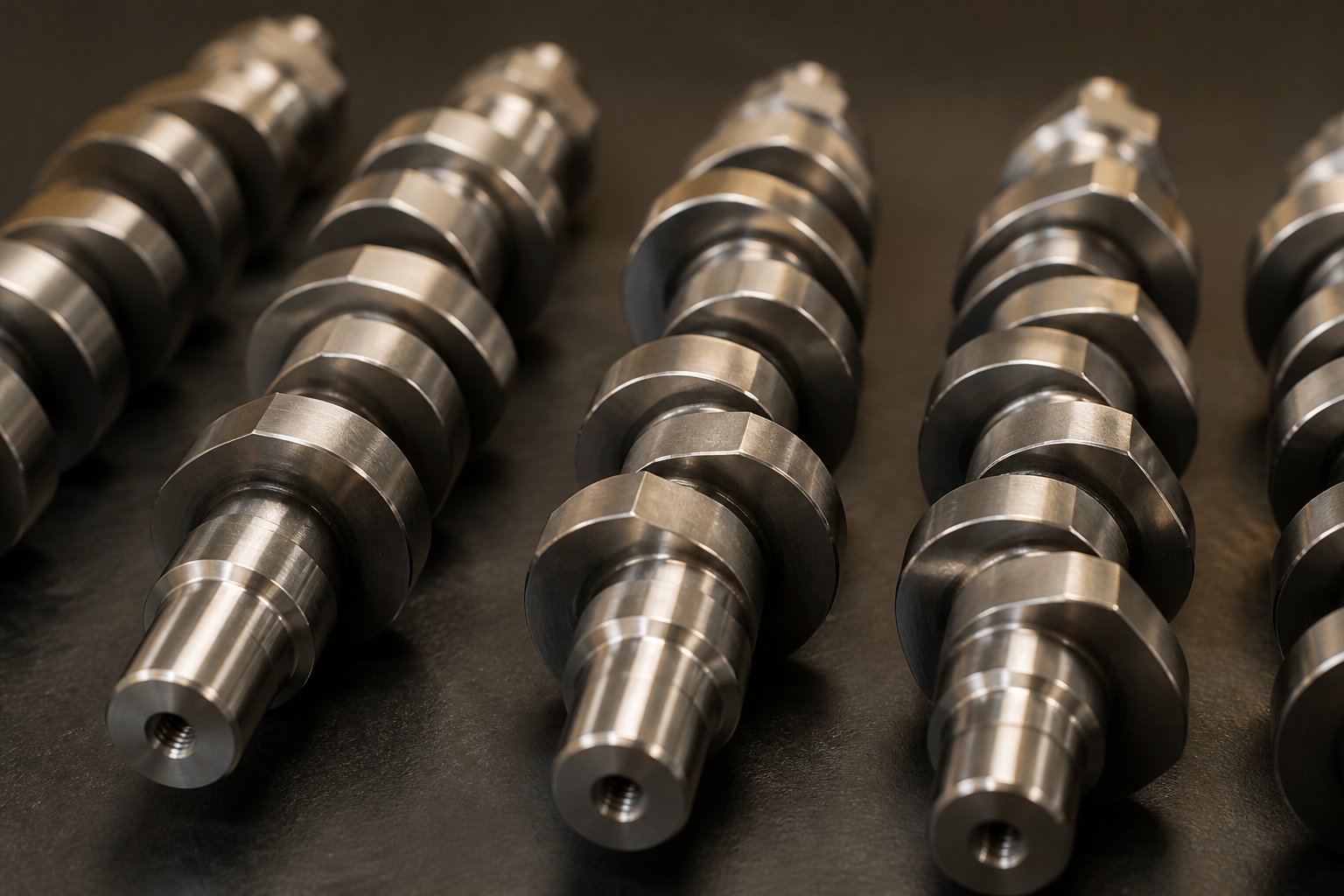
Kneading Blocks and the Science of Mixing
Shear rates jump, residence time spikes, and the material undergoes a fundamentally different experience the moment it enters a kneading block section. Twin screw kneading elements are the primary tools for transforming a loosely combined feed stream into a homogeneous compound — but they can do that job in two very different ways. Understanding the distinction between those two mixing modes, and how a single geometry parameter controls the balance between them, is the key to unlocking kneading block mixing intensity without overworking your material.
Distributive vs. Dispersive Mixing in Kneading Blocks
Picture a handful of pigment powder dropped into a pool of molten polymer. Two separate problems need to be solved before that pigment delivers uniform color. First, the pigment particles may be clumped into agglomerates held together by cohesive forces. Second, even if those clumps are broken apart, the individual particles still need to be spread evenly throughout the melt. These two problems correspond to two distinct mixing mechanisms.
Dispersive mixing is the breakup of agglomerates or immiscible droplets. It requires forcing material through narrow gaps where shear stress exceeds the cohesive or interfacial forces binding particles together. As compounding expert Kenneth Russell explains, wide kneading discs plow through the polymer, smearing material and generating high shear forces that promote this type of breakup. Carbon black is a classic example — its aggregates must be dispersed before the compound develops full, uniform color.
Distributive mixing is the spatial rearrangement of already-separated components. It works by repeatedly splitting and recombining flow streams, spreading additives, pigments, or low-viscosity liquids uniformly across the polymer matrix. Narrow kneading discs slice through the melt in a scissoring action, dividing flow and folding it back together — ideal for gentle incorporation without excessive shear.
Here is the critical point: a material can be dispersed but not distributed (broken into fine particles that remain concentrated in one area), or distributed but not dispersed (spread throughout the matrix as large, unbroken clumps). Effective compounding requires both, and kneading block configuration determines how much of each the process delivers.
How Stagger Angle Determines Mixing Intensity and Conveying
Among all the variables that define kneading block behavior — disc width, number of discs, element length — the kneading block stagger angle stands apart as the dominant performance driver.
Stagger angle is the single most influential parameter in kneading block performance. It controls forward conveying capacity, shear intensity, residence time, and melt temperature rise simultaneously.
The mechanism is intuitive once you visualize it. Each disc in a kneading block is angularly offset from its neighbor. A small offset angle keeps the geometry close to a helical conveying element, maintaining strong forward thrust. As the offset increases, forward motion decreases and the material backs up, filling the channel and exposing it to progressively more intense shear. Industry data on the four mainstream specifications confirms a clear performance hierarchy:
- Axial conveying capacity: 30° > 45° > 60° > 90° (zero conveying)
- Shear and dispersion strength: 90° > 60° > 45° > 30°
- Energy dissipation and degradation risk: 90° > 60° > 45° > 30°
Reverse stagger angles take this logic one step further. By offsetting discs in the opposite rotational direction, the block actively pumps material backward. This creates an extremely restrictive barrier that maximizes fill, residence time, and shear — and simultaneously forms a melt seal. Screw designers typically place a reverse kneading block at the end of a mixing section to ensure the zone stays fully filled, which improves mixing efficiency compared to an all-forward configuration that would remain relatively empty.
A numerical simulation study from China Agricultural University reinforced these relationships quantitatively. Kneading blocks increased leakage flow between discs and generated backflow that extended residence time distribution, facilitating thorough interaction inside the barrel. The study also showed that particles under kneading block action exhibited significantly higher mixing uniformity than under conveying elements alone, with dimensionless concentration values approaching the ideal 0.5 mark.
The table below maps each stagger angle to its processing impact, giving you a practical reference for selecting the right kneading block configuration.
| Stagger Angle | Forward Conveying Effect | Shear Intensity | Residence Time Impact | Typical Application | Effect on Melt Temperature |
|---|---|---|---|---|---|
| 30° (Forward) | Strong — near-conveying behavior | Low | Minimal increase | Initial melting zone; heat-sensitive polymers prone to scorching | Minimal rise |
| 45° (Forward) | Moderate — stable forward transport | Moderate | Slight increase | Standard primary mixing for general-purpose resins; preliminary homogenization | Moderate rise |
| 60° (Forward) | Weak — noticeably reduced conveying | High | Significant increase | Polymer alloy blending; dispersing CaCO3, talc, and TiO2 agglomerates | Obvious rise; monitor for degradation |
| 90° (Neutral) | Zero — no axial conveying | Very high | Large increase; material relies on upstream push | Final dispersion of glass fiber and heavy mineral fillers; pressure building at mixing section end | Peak heat generation; risk of discoloration or scorching if section is too long |
| Reverse | Negative — pumps material backward | Extremely high | Maximum increase; creates fully filled zone | Melt seal formation upstream of vent ports; extreme homogenization; residence time control | Highest rise; use short sections to limit thermal damage |
Notice the pattern: every increase in mixing intensity carries a thermal penalty. Overlong 90° or reverse sections can easily push melt temperature beyond the material's stability window, triggering molecular degradation, discoloration, or scorching. The practical guideline is straightforward — choose 30° or 45° kneading blocks when fast throughput and low thermal risk are priorities, and reserve 60° or 90° blocks for formulations that genuinely demand full filler dispersion and thorough homogenization.
Getting dispersive vs distributive mixing right is essential, but kneading blocks are not the only elements that shape the mixing zone. Reverse elements and several lesser-known specialty components add another layer of control — particularly when the process requires melt seals, precise pressure dams, or ultra-gentle blending that even the mildest kneading block cannot deliver.
Reverse Elements, Melt Seals, and Specialty Components
Kneading blocks get most of the attention in mixing discussions, but some of the most critical processing outcomes — vacuum integrity at vent ports, pressure stability before the die, and ultra-gentle blending of shear-sensitive additives — depend on elements that rarely appear in standard design guides. Reverse screw elements in a twin screw extruder and a handful of specialty components fill exactly these roles, and overlooking them is one of the fastest ways to end up with venting failures, inconsistent output, or needless thermal degradation.
Reverse Elements and Their Role in Melt Seals and Pressure
Reverse (left-handed) conveying elements and reverse kneading blocks use the same helical or disc geometry as their forward counterparts — but wound or staggered in the opposite direction. The result is a segment that actively pumps material backward against the overall flow. What is an example of a screw element that creates intentional resistance? A reverse-pitch flight is the textbook case. Material cannot simply pass through; it must be pushed past the restriction by the upstream pressure generated by forward elements and kneading blocks.
This backward-pumping action serves three critical functions in melt seal screw design:
- Forming melt seals upstream of vacuum vent ports. A reverse element forces the upstream section to fill completely, creating a continuous plug of molten polymer that blocks atmospheric air from being pulled into the barrel through the vent opening. Without this seal, a vacuum pump would simply draw air backward through the melt channel instead of extracting volatiles. As Granuwel's screw configuration principles emphasize, sealing elements must be set upstream of the venting port to establish high pressure, while the vent zone itself should maintain a low fill level so the melt has a large exposed free surface for efficient degassing.
- Building localized pressure before restrictive die openings or screen packs. Some die geometries or fine-mesh filtration screens demand higher inlet pressure than a standard metering section can provide. A short reverse element placed upstream creates a pressure dam that pre-loads the melt, smoothing flow and reducing output fluctuations.
- Controlling residence time distribution by creating filled zones. Every reverse element forces the barrel section immediately upstream to run at or near 100% fill. This extends the time material spends in that region, which is useful when a reactive system needs a guaranteed minimum dwell time for chemical conversion — but risky if the polymer is heat-sensitive.
Vent port placement is directly tied to this logic. The vent opening must sit immediately downstream of the reverse element, in the low-pressure, partially filled zone that forms once material clears the restriction. Placing a vent upstream of the melt seal — where pressure is high and the channel is fully packed — would cause molten polymer to extrude out through the port instead of allowing gas to escape. The sequencing rule is absolute: reverse element first, then vent port in the decompressed zone that follows.
Specialty Elements Beyond Standard Configurations
Forward conveying elements, kneading blocks, and reverse segments handle the vast majority of processing tasks. Yet certain formulations and operations demand behaviors that these standard configurations cannot deliver on their own. That is where specialty elements come in — purpose-built geometries that target specific mixing, sealing, or pressure needs.
- Screw mixing elements (SME) with channels cut into flight tips. These elements feature slots or grooves machined across the flight crests, allowing a controlled amount of material to leak from one channel into the next. The result is enhanced distributive mixing at significantly lower shear than a kneading block delivers. Typical placement is in post-melting zones where additives need gentle incorporation — for instance, when blending temperature-sensitive stabilizers or liquid additives into a polymer melt. Rotor-style grooved screw elements (sometimes labeled RGS for right-handed or LGS for left-handed grooved screws) are a common variant, combining conveying action with distributive flow splitting.
- Blister rings. A blister ring extruder element is essentially a cylindrical sleeve with a very narrow annular gap between its outer surface and the barrel wall. Material must squeeze through this thin clearance to pass downstream, creating an effective melt seal without any backward-pumping action. Unlike reverse elements, blister rings do not increase torque demand or add shear energy to the melt — they simply restrict flow passively. Engineers place them upstream of vent ports when the formulation cannot tolerate the additional shear and temperature rise that a reverse element would introduce.
- Toothed or gear-type mixing elements. These disc-shaped components feature interlocking teeth or gear-like profiles that repeatedly divide and recombine the melt stream at high frequency. They excel at ultra-high distributive mixing — spreading liquid colorants, low-viscosity additives, or molten waxes uniformly throughout a polymer matrix — while generating far less viscous heating than an equivalent-length kneading block section. Industry practice positions gear-shaped elements alongside kneading blocks in mixing sections where both distribution and gentle dispersion are needed simultaneously.
- Discharge or pressure-buildup elements. Located at the very end of the screw profile, these elements are engineered to build consistent, stable pressure at the screw tip for uniform die feeding. They typically feature reduced pitch and, in some designs, a single flight rather than a double flight to maximize forward pumping while minimizing pulsation. Wide-flighted discharge elements also help prevent material from backing up and overflowing at the die adapter.
Standard conveying and kneading elements handle roughly 90% of the processing work, but it is the remaining 10% — reverse segments, blister rings, and specialty mixing geometries — that often determines whether a screw profile succeeds or fails at the margins.
Each of these elements occupies a specific position along the barrel for a reason, and that position depends on which processing zone it serves. Mapping every element type to its correct zone — and understanding the sequencing logic that governs transitions between zones — is the next step toward assembling a complete, functional screw profile.
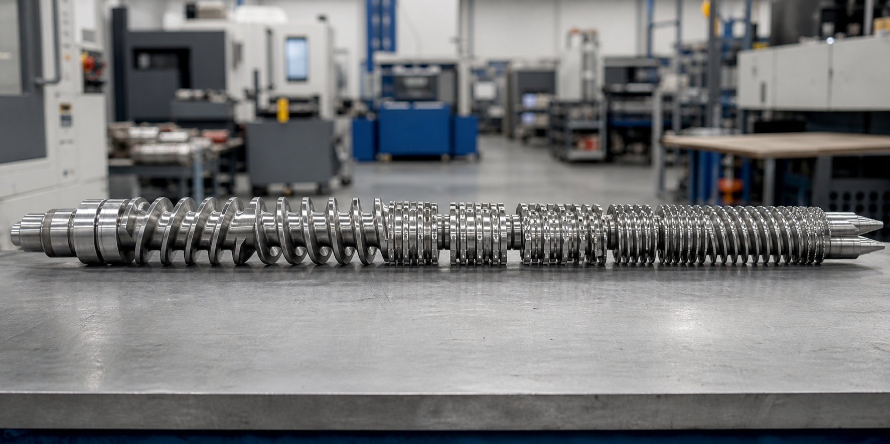
The Processing Zone Framework for Screw Profile Design
Knowing what each element does in isolation is one thing. Knowing exactly where it belongs on a 36D or 48D barrel — and why it belongs there instead of two zones upstream — is something else entirely. This distinction separates a parts catalog from a functioning screw profile design guide. Every barrel can be divided into distinct functional zones, and each zone has a clear job, a preferred set of elements, and geometry choices that serve that job. Mapping those relationships turns screw profile assembly from guesswork into a systematic, repeatable engineering process.
Mapping Screw Elements to Five Core Processing Zones
Imagine walking along the barrel from feed throat to die adapter. The material transforms at every stage — from loose pellets to a softening bed, then to a fully molten compound, through a degassing section, and finally into a pressurized stream ready for shaping. Each transformation defines a twin screw extruder processing zone, and the elements installed in that zone must match the transformation happening there.
Here are the five core zones, what they accomplish, and which elements make them work:
1. Solids conveying zone. This is where raw pellets, powder, or flakes enter the barrel from the hopper or gravimetric feeder. The material is cold, unmelted, and often low in bulk density. The zone's sole purpose is to accept feed reliably and move it downstream without compressing it prematurely. Large-pitch forward conveying elements dominate here because their deep, wide channels maximize intake volume and prevent bridging. As NC State Extension's screw design research notes, the deeper flights of conveying elements enable efficient material transport without imparting significant shear or breaking down ingredients — exactly the behavior you want when the material is still solid.
2. Melting and plastication zone. Downstream of the feed section, the barrel temperature rises and the screw geometry begins to consolidate and melt the material. This zone transitions from conveying elements with progressively decreasing pitch into the first kneading block sections. Advancing stagger angles — typically 30° or 45° — combine moderate shear with continued forward conveying, generating enough viscous dissipation to initiate melting without causing thermal shock. The goal is a complete, uniform melt by the end of this zone.
3. Mixing and compounding zone. This is where the heavy lifting happens. Additives, fillers, pigments, and blend partners must be dispersed and distributed throughout the melt. Kneading blocks with 60° or 90° stagger angles deliver the high shear intensity needed for dispersive action — breaking apart agglomerates and reducing droplet size in immiscible blends. Toothed mixing elements or screw mixing elements (SME) may supplement the kneading blocks for enhanced distributive blending. A reverse kneading block or short reverse conveying element often caps this zone, ensuring the section runs fully filled for maximum mixing efficiency.
4. Venting and devolatilization zone. Moisture, residual monomers, and entrapped air must be removed before the compound reaches the die. This zone sits immediately downstream of a melt seal — created by reverse elements at the end of the mixing zone — where pressure drops sharply and the channel becomes partially filled. Large-pitch conveying elements are essential here because they reduce the degree of fill, exposing a greater melt surface area to the vacuum. Process optimization guidelines emphasize that the fill level in the venting zone must stay below 30% to prevent vent flooding, and the screw configuration must use deep-flighted, low-shear forward elements to avoid pressure buildup that would force volatiles back into the melt.
5. Pressure buildup and metering zone. The final zone builds stable, consistent forward pressure to push melt through screen packs, breaker plates, and the die. Tight-pitch conveying elements are the standard choice — their reduced free volume raises the degree of fill toward 100% and generates the pressure gradient the die geometry demands. Discharge elements with reduced pitch or single-flight configurations may appear at the very tip for additional pressure smoothing and pulsation control.
The table below consolidates this extruder barrel zone element mapping into a single reference, connecting each zone to its function, recommended elements, geometry priorities, and target outcome.
| Processing Zone | Zone Function | Recommended Element Types | Key Geometry Choices | Target Processing Outcome |
|---|---|---|---|---|
| Solids Conveying | Accept feed from hopper; transport unmelted material downstream | Large-pitch forward conveying elements (e.g., 1.5D-2.0D pitch) | Maximum channel depth; wide pitch for high free volume; double-flight for wiping | Reliable intake; no bridging; minimal shear on cold material |
| Melting / Plastication | Consolidate and melt the material through shear and barrel heat | Decreasing-pitch conveying elements transitioning to 30°-45° kneading blocks | Gradual pitch reduction; narrow-to-moderate disc width; advancing stagger angles | Complete, uniform melt with controlled temperature rise |
| Mixing / Compounding | Disperse fillers; distribute additives; homogenize blends | 60°-90° kneading blocks; toothed mixing elements; SME elements; reverse kneading block to seal | Wide discs for dispersive mixing; narrow discs for distributive; 90° stagger for maximum shear | Uniform filler dispersion; homogeneous melt; target particle size reduction |
| Venting / Devolatilization | Remove moisture, volatiles, and entrapped air under vacuum | Large-pitch forward conveying elements (preceded by reverse element or blister ring for melt seal) | Maximum pitch and channel depth to minimize fill; low shear to avoid re-entraining gas | Fill level below 30%; large exposed melt surface; no vent flooding |
| Pressure Buildup / Metering | Build stable pressure for uniform die feeding | Tight-pitch forward conveying elements; discharge elements at screw tip | Reduced pitch (0.5D-0.75D); high fill approaching 100%; single-flight option for extra pumping | Consistent die pressure with minimal pulsation; steady output rate |
You'll notice that conveying elements appear in every single zone — but their pitch and flight depth change dramatically from one end of the barrel to the other. A 2.0D pitch element in the feed section and a 0.5D pitch element in the metering section may share the same basic helical geometry, yet they produce completely different fill levels, pressures, and residence times. The zone dictates the geometry, not the other way around.
Sequencing Logic and Transition Rules
Selecting the right elements for each zone solves half the problem. The other half — and arguably the half where most screw element sequencing rules get broken — is how you transition between zones. Abrupt changes in element geometry create process instabilities: pressure spikes, torque surges, localized overheating, and poor mixing uniformity. Smooth transitions keep the material moving predictably through each processing stage.
Four principles govern effective sequencing:
- Transition gradually from conveying to mixing. Never jump directly from a large-pitch conveying element into an aggressive 90° kneading block. The sudden loss of forward conveying capacity and the spike in shear would cause a severe pressure dam, excessive torque, and a sharp melt temperature rise. Instead, step through intermediate elements — reduce pitch progressively, then introduce kneading blocks starting with a mild 30° or 45° stagger before moving to 60° or 90° sections. This progressive shear increase gives the material time to consolidate and soften before encountering high-intensity mixing.
- Place narrow kneading discs before wider ones. Narrow discs produce frequent but gentle flow-splitting events — primarily distributive mixing. Wider discs deliver fewer but more intense shear events — primarily dispersive mixing. Sequencing narrow before wide mimics how mixing logically proceeds: spread the additive throughout the matrix first, then break apart any remaining agglomerates. Reversing this order wastes energy by trying to disperse clumps that haven't yet been distributed, and it risks thermal damage from applying maximum shear too early.
- Position reverse elements only where a melt seal or pressure dam is functionally required. Every reverse element adds torque load, raises melt temperature, and extends residence time. Using one where it isn't needed — say, between two kneading sections that could be separated by a simple conveying re-stabilization zone — introduces thermal risk without a processing benefit. The two primary locations where reverse elements are essential are upstream of vent ports (to create the melt seal that enables vacuum degassing) and at the end of a mixing section (to ensure full fill for effective kneading). Everywhere else, a conveying element is the safer, cooler choice.
- Ensure adequate conveying length after each mixing section. After every kneading block or restrictive element, a run of forward conveying elements must re-establish stable, partially filled flow before the next processing event. This re-conveying zone serves three purposes: it relieves the localized pressure created by the mixing section, it allows some heat to transfer through the barrel wall (reducing the cumulative melt temperature rise), and it gives the flow time to stabilize before encountering another disruption. Skipping this step — stacking two kneading sections back to back without an intervening conveying zone — is one of the most common profile design mistakes, and it almost always results in excessive melt temperatures and unpredictable residence time distribution.
A well-sequenced screw profile reads like a story: it introduces the material gently, builds intensity progressively, provides recovery periods between demanding sections, and finishes with a steady, pressurized delivery to the die.
These sequencing rules apply universally, but the specific combination of elements — how many kneading blocks, how aggressive the stagger angles, how many vent zones — changes dramatically depending on what operation the extruder is performing. A compounding profile for mineral-filled polypropylene looks nothing like a devolatilization profile for recycled PET, even though both are built from the same element catalog. Translating zone-by-zone logic into operation-specific screw profiles is where theory meets the production floor.
Building Screw Profiles for Specific Processing Operations
A screw profile built for compounding glass-fiber-reinforced nylon shares almost no element sequence with one designed for stripping residual solvent from recycled PET. Both use the same catalog of conveying elements, kneading blocks, and reverse segments — yet the combination, placement, and stagger angles diverge so sharply that swapping one profile into the other's application would produce unusable product. That gap between universal zone logic and real-world results is where operation-specific screw chemistry comes in.
Screw Profiles for Compounding, Pelletizing, and Masterbatch
Each of these three operations places a different demand at the top of the priority list: compounding needs mixing intensity, pelletizing needs pressure stability, and masterbatch production needs pigment distribution. The element lineup reflects those priorities directly.
Compounding. A typical screw profile for compounding extrusion features two or even three separate kneading block zones distributed along the barrel, each with progressively more aggressive stagger angles. The first kneading section — usually 30° to 45° blocks — initiates melting and gentle premixing. A second section steps up to 60° or 90° blocks for full dispersive action on fillers or blend partners. Conveying elements separate these mixing zones to relieve pressure, allow barrel-wall cooling, and re-establish stable flow. Optimized compounding configurations often install large-lead conveying elements between the feeding and kneading zones to reduce fill level and increase throughput capacity at the same screw speed.
- Start with large-pitch conveying elements in the feed zone for maximum intake volume.
- Step pitch down gradually through a transition zone to begin material consolidation.
- Introduce a first kneading block set at 30°-45° stagger to initiate melting and light mixing.
- Follow with a conveying re-stabilization section to relieve pressure and manage temperature.
- Place a second, more aggressive kneading block set at 60°-90° stagger for full dispersive mixing of fillers or immiscible phases.
- Cap the mixing zone with a short reverse element to ensure full fill and maximum mixing efficiency.
- If a vent port is present, use large-pitch conveying elements immediately downstream of the melt seal for degassing.
- Finish with tight-pitch metering elements to build stable die pressure.
Pelletizing. Pelletizing profiles share many upstream features with compounding layouts, but the metering zone gets extra attention. Consistent strand or underwater pellet output depends on stable, pulsation-free pressure at the die. Tight-pitch conveying elements — sometimes paired with a single-flight discharge segment — occupy a longer section at the screw tip than a typical compounding profile would use. The result is a smoother pressure gradient and more uniform pellet geometry.
Masterbatch. Masterbatch screw profile configuration prioritizes distributive mixing above all else. Pigments must be spread uniformly throughout the carrier resin without overheating the concentrate. Profiles for this application lean on combinations of narrow-disc kneading blocks, toothed mixing elements, and screw mixing elements (SME) that split and recombine flow at high frequency but low shear. Wide-disc, high-stagger kneading blocks are used sparingly — only where pigment agglomerates genuinely need dispersive breakup. Calcium carbonate masterbatch production, for example, demands strong shear dispersion at specific points to break agglomerates, but the rest of the profile should remain gentle to avoid resin degradation and maintain uniform color.
Profiles for Devolatilization, Reactive Extrusion, and Side Feeding
These three operations push screw design into more specialized territory. Each one hinges on a particular element-to-zone relationship that, if missed, causes the entire process to fail.
Devolatilization. Effective devolatilization screw element design revolves around two non-negotiable requirements: airtight melt seals upstream of every vent port and maximum surface area exposure in the vent zone itself. As devolatilization specialist Rob Jerman explains, a volatile species will leave a solution only at a gas-liquid interface — the larger that interface, the faster the stripping. Multiple flights, steeply pitched screws, and interrupted flights all contribute to maximizing the rate of surface renewal in the partially filled vent zone.
- Build a melt seal using a reverse kneading block or blister ring immediately upstream of the vent port.
- Place large-pitch, deep-channel conveying elements in the vent zone to keep fill level well below 30%, maximizing exposed melt surface area.
- Use multi-flighted conveying elements or interrupted-flight designs to increase surface-area regeneration rate as the screw rotates.
- If multiple vents are required, repeat the melt-seal-then-vent sequence for each stage — each vent can reduce volatile concentration by roughly an order of magnitude.
- Ensure sufficient conveying length between the vent opening and the downstream seal to prevent polymer from backing up into the vent port.
Reactive extrusion. Reactive systems — grafting, chain extension, controlled degradation — need a guaranteed minimum residence time for the reaction to reach completion. Yet excessive dwell time means thermal degradation. The solution is strategic placement of 90° kneading blocks and reverse elements to create controlled filled zones where reaction occurs, separated by conveying sections that limit cumulative heat exposure. The profile essentially creates "reaction chambers" along the barrel, each bounded by restrictive elements that hold material long enough for chemistry to proceed, then release it into a cooling and re-conveying section before the next stage.
- Feed reactive components — polymer plus peroxide, silane, or chain extender — through the main hopper or a downstream liquid injection port.
- Melt and premix using moderate kneading blocks (45° stagger) to ensure uniform reagent distribution before the reaction zone.
- Create a filled reaction zone using 90° kneading blocks capped with a short reverse element — this guarantees the residence time the reaction kinetics require.
- Follow immediately with forward conveying elements to relieve pressure and allow barrel cooling, preventing thermal runaway.
- If volatiles are generated by the reaction, place a vacuum vent downstream of the reaction zone with a proper melt seal sequence.
- Close with tight-pitch metering elements for stable die feeding.
Side feeding. When fillers like glass fiber or calcium carbonate enter downstream through a side stuffer, the screw profile at that location must present a low-fill, high-conveying section. If the channel is already packed with melt, the side-fed material has nowhere to go — it backs up in the stuffer barrel or fails to incorporate. Large-pitch conveying elements directly under the side-stuffer opening draw material into the melt stream quickly. Screw configuration optimization strategies recommend a dedicated transport zone between the side-feed port and the downstream kneading section to ensure that fillers are fully wetted before encountering high shear.
- Install large-pitch forward conveying elements at the side-stuffer location to maximize available channel volume for incoming filler.
- Ensure the upstream melt seal or mixing section has already fully melted the base resin, so the filler encounters liquid polymer rather than unmelted solids.
- Provide a short conveying transport zone after the side feed to allow initial wetting and distribution of the filler in the melt.
- Place a kneading block section downstream for final dispersion of the filler — using moderate stagger angles for brittle fibers like glass to avoid excessive fiber breakage.
Across all six operations, one theme recurs: the screw profile is only as good as the dimensional accuracy of each individual segment. A kneading block that is 0.2 mm oversize on its OD changes the tip-to-barrel clearance enough to alter shear rates and pressure generation. A conveying element with a worn spline bore wobbles on the shaft, introducing pulsation and uneven fill. Sourcing precise, interchangeable modular segments — kneading blocks, conveying elements, and specialty components manufactured to exact drawings or measured dimensions — is essential for executing any of these profiles reliably. For teams in compounding, pelletizing, masterbatch, and recycling operations, suppliers like NANHAIYA offer custom twin screw elements and segment screw assemblies produced to OEM specifications, ensuring that each modular segment maintains the tight tolerances these profiles demand.
Selecting the right element combination for a given operation solves the process design challenge. But a separate question lurks beneath every profile decision — which elements suit the material running through the barrel? A gentle masterbatch profile becomes destructive if applied to a heat-sensitive bioplastic, and an aggressive compounding layout may be too mild for 60% glass-fiber loadings. Material properties, not just process goals, must shape the final element choices.
How Material Type Shapes Screw Element Selection
A perfectly sequenced screw profile means nothing if it ignores what the material actually needs. Two formulations running on the same extruder at identical screw speeds can demand completely different element configurations — one thriving under aggressive 90° kneading blocks, the other degrading within seconds. The polymer's viscosity, thermal stability, filler content, and chemical reactivity each impose constraints that override generic profile templates. Matching elements to the material — not just to the process zone — is where screw design becomes truly effective.
Element Selection for Unfilled Polymers and Heat-Sensitive Materials
Unfilled polymers present a deceptively simple challenge. There are no agglomerates to break apart and no abrasive particles to worry about, so the temptation is to run a mild, unoptimized profile and call it done. The real risk, though, is unnecessary shear. Every kneading block adds viscous dissipation that raises melt temperature — and in an unfilled system, that extra energy has no productive mixing work to do. It simply overheats the resin.
Effective profiles for neat polymers use advancing kneading blocks in the 30° to 45° stagger range, kept short in total length. A single kneading section is often sufficient to complete melting and achieve basic homogenization. Longer or more aggressive mixing zones push melt temperature above the material's processing window without improving product quality. Standard-pitch conveying elements handle the rest of the barrel, providing smooth transport with minimal shear contribution.
Heat sensitive material extrusion screw design takes this philosophy even further. Materials like PVC, certain bioplastics, and thermally unstable engineering resins degrade rapidly when exposed to high shear or extended residence time. PVC, for instance, releases hydrochloric acid above its relatively narrow processing window, triggering autocatalytic degradation that ruins the entire batch. Biopolymers such as PLA and PHA lose molecular weight under even moderate shear intensity, reducing mechanical properties in the finished part.
Profiles for these materials share several common features:
- Large-pitch conveying elements throughout most of the barrel — keeping fill levels low, shear rates minimal, and residence time short.
- Minimal kneading block length — often just a few disc widths of 30° advancing stagger, placed only where melting absolutely requires it.
- Screw mixing elements (SME) instead of kneading blocks for distributive blending — the grooved flight tips split and recombine flow gently, achieving additive incorporation without the intense shear that disc-type kneading blocks produce.
- No 90° or reverse kneading blocks unless a melt seal is functionally mandatory — every neutral or backward-pumping element extends residence time and adds thermal energy, both of which heat-sensitive formulations cannot tolerate.
As NC State Extension's extrusion research emphasizes, a shear-sensitive material often fails to form a stable product when extruded using a high-shear screw profile. The ideal configuration efficiently conveys and melts the material while developing appropriate temperature and pressure at the die — without overworking the polymer along the way.
Element Selection for Highly Filled Compounds and Reactive Systems
Imagine pushing a compound loaded with 50% glass fiber or 60% calcium carbonate through a screw profile designed for neat resin. Two things happen almost immediately: the elements wear at an alarming rate, and the filler never fully disperses. Screw elements for filled polymers face demands that unfilled profiles never encounter — abrasive particle contact on every surface, higher torque loads from increased melt viscosity, and the need for intense but concentrated mixing to break apart filler agglomerates without destroying fiber length.
A glass fiber compounding screw profile, for example, must balance dispersion against fiber attrition. Glass fibers break under excessive shear — and once broken, they lose the length that gives the composite its mechanical advantage. Profiles for glass-fiber compounds typically use wider kneading blocks with moderate stagger angles (45° to 60°) in a single, well-defined mixing zone rather than multiple distributed kneading sections. Fewer but more targeted mixing events reduce total element exposure to the abrasive glass while still achieving adequate fiber wetting and distribution. Side-fed glass fiber profiles position the kneading section immediately downstream of the side stuffer, minimizing the distance — and number of elements — the abrasive-laden melt must traverse.
Extrusion screw research for thermoplastic composites confirms that fillers like mica and fiberglass cause aggressive wear starting in the feed section, with abrasion concentrated on the push side of flights where solid pellets carrying surface-exposed filler particles grind against unprotected steel. Calcium carbonate produces more gradual, widespread abrasive wear across flight surfaces, while titanium dioxide can introduce both abrasion and chemical corrosion depending on processing temperatures and moisture levels. Each filler type demands not only a different element layout but also careful attention to element material selection — nitrided surfaces, tungsten-carbide coatings, or fully encapsulated flight roots — to extend service life.
Reactive extrusion screw element selection introduces yet another constraint: time. Reactive systems — peroxide-initiated grafting, silane crosslinking, chain extension with epoxy-functional additives — need a guaranteed minimum residence time for the chemical reaction to reach completion. Too little dwell and the product is under-reacted; too much and the polymer degrades thermally. The profile must create controlled filled zones where the reaction proceeds, bounded by restrictive elements that hold material just long enough.
Strategic placement of 90° kneading blocks and short reverse elements creates these "reaction chambers." The neutral and reverse stagger angles eliminate forward conveying, forcing the channel to fill completely. Material dwells in this filled zone long enough for the reaction kinetics to play out, then exits into forward conveying elements that relieve pressure and allow barrel-wall cooling before the next stage. Monitoring torque and melt temperature at each reaction zone provides real-time feedback on reaction progress — a rising torque trend often signals increasing molecular weight from successful chain extension, while a falling trend may indicate degradation.
The table below maps these four material categories to their recommended element strategies, giving you a quick-reference framework for matching your formulation to the right screw element choices.
| Material Category | Recommended Element Types | Mixing Intensity Level | Key Geometry Choices | Primary Processing Risk to Manage |
|---|---|---|---|---|
| Unfilled Polymer | Standard-pitch conveying elements; short 30°-45° kneading block section; optional SME for gentle blending | Low to moderate | Moderate pitch throughout; minimal kneading block length; no reverse elements unless venting is required | Excessive melt temperature rise from unnecessary shear — causes yellowing, reduced clarity, or molecular weight loss |
| Highly Filled Compound (glass fiber, CaCO3, TiO2 >40%) | Wide-disc kneading blocks at 45°-60° in a single concentrated mixing zone; large-pitch conveying at side-feed location; wear-resistant element materials | High but concentrated | Fewer, more intense mixing zones to minimize total abrasive contact; moderate stagger to balance dispersion against fiber breakage; tight-pitch metering for pressure stability with high-viscosity melt | Accelerated element wear from abrasive fillers; fiber attrition from excessive shear; barrel temperature override from high-viscosity drag |
| Reactive System | 45° kneading blocks for premixing; 90° kneading blocks and short reverse elements to create filled reaction zones; forward conveying between reaction stages for cooling | Moderate to high in reaction zones; low between stages | 90° and reverse elements sized precisely to deliver target residence time; conveying sections long enough to dissipate heat between reaction chambers | Incomplete reaction from insufficient residence time, or thermal degradation from excessive dwell — both controlled by reverse element length and placement |
| Heat-Sensitive Material (PVC, bioplastics, certain TPEs) | Large-pitch conveying elements as dominant component; minimal 30° kneading blocks; SME or toothed mixing elements for distributive blending; blister rings preferred over reverse elements for melt seals | Low | Maximum pitch and channel depth to minimize residence time; shortest possible kneading sections; blister ring seals instead of reverse elements to avoid shear-induced heating | Thermal degradation, discoloration, off-gassing, or autocatalytic decomposition from excessive temperature or residence time |
The material dictates the profile, not the other way around. Every element choice — stagger angle, disc width, pitch, even element metallurgy — should trace back to a specific property of the compound being processed.
Choosing the right elements for your material solves the design problem on day one. Keeping those elements performing as designed over thousands of operating hours is an entirely different challenge — one driven by wear patterns that vary as dramatically between filler types as the screw profiles themselves.
Wear Management and Sourcing Quality Replacement Twin Screw Extruder Elements
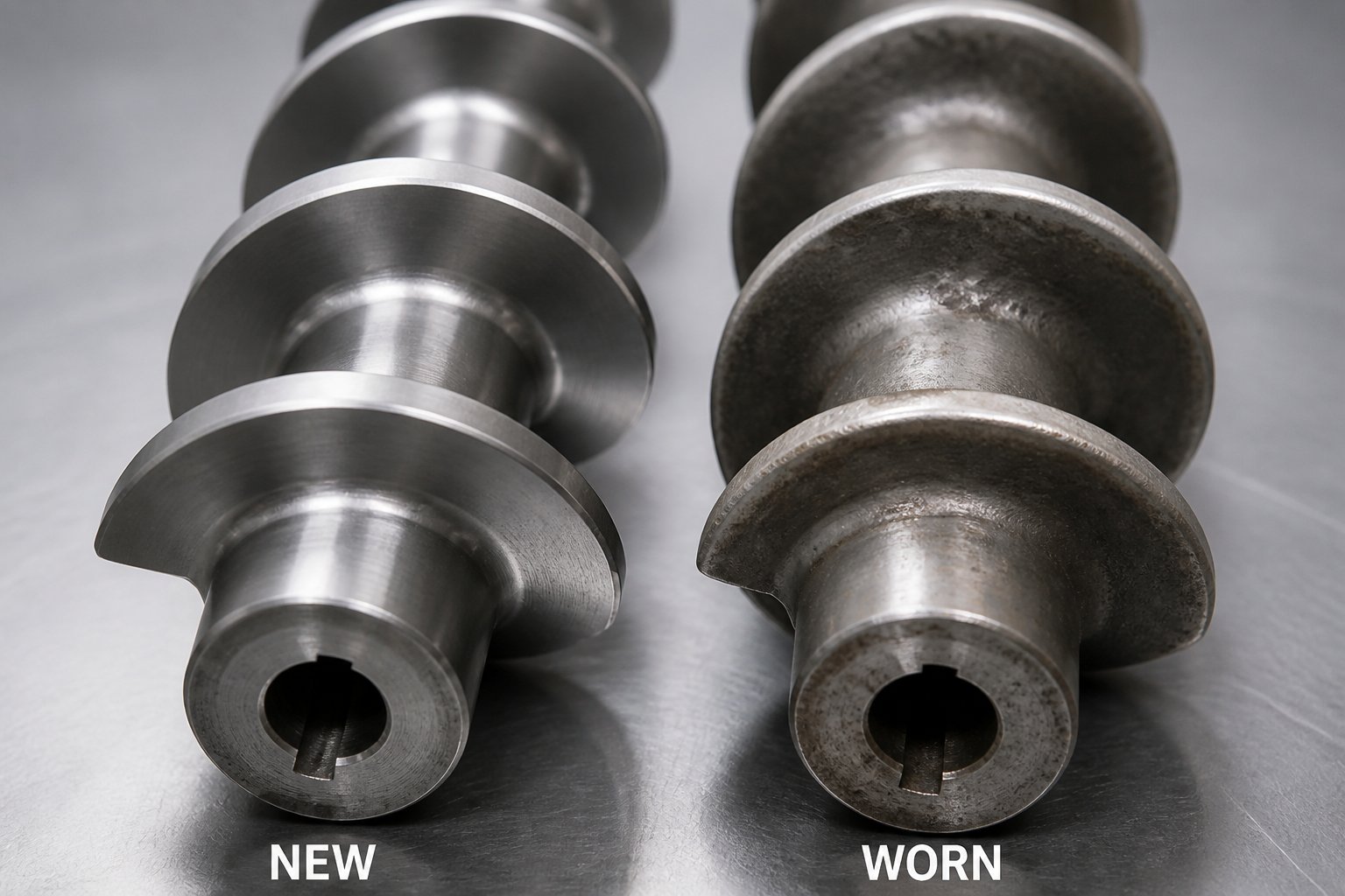
A screw profile designed perfectly for your material can still drift out of specification — not because the design was wrong, but because the elements themselves are slowly changing shape. Every hour of operation grinds away metal at flight tips, kneading disc edges, and barrel-to-element clearances. Left unchecked, that gradual erosion reshapes the very geometry parameters discussed throughout this article, silently degrading mixing efficiency, pressure generation, and product quality. Understanding where wear concentrates, how it alters processing behavior, and what to look for in replacement elements is the difference between proactive maintenance and reactive crisis management.
Wear Patterns Caused by Abrasive Fillers and Processing Conditions
Screw element wear patterns are never uniform. Some surfaces endure far more abrasive contact than others, and the type of filler running through the barrel determines exactly where the damage accumulates fastest.
Flight tips on conveying elements experience the highest mechanical stress. The narrow radial gap between the flight crest and the barrel wall is where material gets sheared, compressed, and dragged forward. Abrasive particles trapped in that gap act like sandpaper, grinding the flight OD down with every rotation. Industry testing across multiple resin systems confirms that the majority of OD wear concentrates in high-pressure zones — particularly the transition section and the last few turns of metering — where elevated pressure and temperature amplify friction rates.
Kneading block surfaces suffer a different pattern. The narrow intermeshing gaps between disc tips and the barrel bore see intense abrasive contact during dispersive mixing. Wide-disc kneading blocks processing mineral fillers erode along their leading edges first, gradually rounding the sharp profiles that generate the high shear stress needed to break apart agglomerates. As the disc tips wear, the effective clearance widens and shear intensity drops — undermining the very function the kneading block was installed to perform.
Each filler type leaves a distinct wear signature:
- Glass fiber causes erosive wear concentrated on the forwarding side of flight edges. Long fibers entangle at the feed port and shear during rotation, forming sharp particles that intensify abrasion — particularly in the side-feed zone where unmelted filler first contacts the screw.
- Calcium carbonate produces gradual, widespread abrasive wear across flight surfaces and disc faces. The particles are less aggressive than glass individually, but their high loading levels (often 60% or more in masterbatch) create relentless cumulative erosion.
- Titanium dioxide can cause both mechanical abrasion and chemical corrosion depending on processing temperature and moisture content. The combination accelerates surface degradation beyond what abrasion alone would produce.
Worn elements change processing behavior in predictable ways. As flight OD decreases, the radial clearance between screw and barrel grows. Material leaks backward through this enlarged gap instead of being conveyed efficiently, reducing output at any given screw speed. Rate-loss modeling shows that a lower-viscosity resin suffers more throughput loss than a higher-viscosity one at the same clearance — meaning the same amount of wear has a bigger impact on polypropylene than on polyethylene. Operators typically compensate by increasing screw speed, which raises energy consumption and pushes melt temperature higher, often leading to degradation, discoloration, or inconsistent pellet quality.
The performance cascade is worth spelling out clearly:
- Increased clearance reduces shear rate and pressure generation capacity.
- Backward leakage flow increases, cutting effective throughput.
- Mixing efficiency degrades as kneading disc profiles lose their sharp edges.
- Melt temperature rises because higher rpm is needed to maintain output, adding frictional heat.
- Product quality metrics — color consistency, mechanical properties, surface finish — begin to drift.
That quality drift is often the first detectable signal. Monitoring metrics like color delta-E values, tensile strength, or pellet weight uniformity over time can flag when elements need replacement well before a catastrophic failure — a chipped flight breaking loose, a scored barrel bore, or a seized shaft — forces an emergency shutdown. Screw wear specialists recommend establishing baseline performance data when elements are new and tracking deviations against that reference. A common guideline considers replacement warranted when flight clearance reaches approximately four times the original tolerance, though the actual threshold depends on resin viscosity and quality requirements.
Choosing Reliable Sources for Replacement Screw Elements
When worn elements finally come off the shaft, the replacement parts must reproduce the original working geometry — not simply approximate it. Even small dimensional deviations ripple through the entire screw profile. A systematic analysis of post-replacement performance issues found that output frequently fails to recover to its original level, and the most common root causes trace directly back to element dimensional accuracy: OD undersized from copying worn samples, spline bores that don't match shaft geometry, or element lengths that create cumulative axial gaps when assembled.
Critical dimensions that must match the original design include:
- Outer diameter (OD) — determines the flight-tip-to-barrel clearance that controls shear rate, leakage flow, and pressure generation.
- Inner diameter (ID) and bore profile — must match the shaft spline geometry precisely to prevent wobble, uneven torque transfer, and vibration under load.
- Spline geometry — tooth count, pressure angle, and root diameter must engage the shaft without play. A worn spline allows micro-movement that accelerates both element and shaft wear.
- Element length — cumulative length of all elements on the shaft must equal the designed total. Even a 1-2 mm gap between elements can allow material to stagnate, degrade, and generate black specks in the product.
- Flight profile and edge sharpness — conveying elements need clean helical edges for efficient drag flow, and kneading discs need precise tip profiles for effective shear generation.
One of the most valuable advantages of modular screw element systems is the ability to replace only the worn sections rather than discarding an entire screw assembly. A profile with 30 or more individual segments may have only four to six elements showing significant wear — typically the kneading blocks in the mixing zone and the tight-pitch conveying elements in the metering section. Targeted replacement of those segments restores profile performance at a fraction of the cost and downtime of a full screw rebuild.
However, mixing new and old elements on the same shaft introduces its own risk. Engineering assessments caution that a large OD difference between new and adjacent worn elements creates abrupt geometry changes in the screw channel — sudden steps in clearance that cause localized pressure spikes, uneven fill, and potential torque instability. The solution is to inspect adjacent elements dimensionally and replace the entire functional group (for example, a complete kneading block set plus its neighboring conveying elements) when the wear differential becomes significant.
The supplier you choose for replacement twin screw extruder elements directly affects whether the restored profile matches its design intent. For teams in compounding, pelletizing, masterbatch, and recycling operations, NANHAIYA's twin screw elements and segment screw product line offers kneading blocks, conveying segments, and custom screw elements produced to precise specifications — whether working from original OEM drawings, physical samples, or reverse-engineered measurements from existing worn parts.
When evaluating any screw element supplier, the following criteria separate reliable sources from those that create more problems than they solve:
- Dimensional accuracy — Can the supplier hold OD, ID, and spline tolerances tight enough to maintain designed clearances? Ask for inspection reports with actual measured values.
- Material grade options — Does the supplier offer tool steels, nitrided surfaces, powder metallurgy (PM) steel, or tungsten-carbide coatings for abrasive filler screw wear management? PM steel delivers finer grain structure and superior wear resistance compared to standard alloy steels, making it a strong choice for high-filler applications.
- Lead time — Worn elements mean lost production. A supplier with stocked standard sizes and fast turnaround on custom orders minimizes the gap between identifying wear and restoring performance.
- Ability to work from drawings or samples — Not every plant has original OEM drawings on file. A capable supplier can reverse-engineer elements from physical samples or measured dimensions, reconstructing the intended working geometry rather than copying the worn state of an old part.
- Range of element types covered — A single source for conveying elements, kneading blocks, reverse segments, toothed mixing elements, and discharge components simplifies procurement, ensures geometric consistency across the full screw profile, and reduces the risk of mismatched tolerances between suppliers.
Replacement elements should restore the profile to its designed performance — not merely fill the space left by worn parts. Dimensional precision, material selection, and system-level compatibility determine whether a replacement returns your process to baseline or introduces new instabilities.
Screw element wear is inevitable in any twin screw operation, but its impact on product quality and process economics is entirely manageable. Establish baseline performance data when elements are new, monitor quality metrics for early drift signals, inspect element dimensions during planned shutdowns, and source replacements that match original specifications precisely. That disciplined approach keeps a well-designed screw profile performing as intended — shift after shift, formulation after formulation.
Frequently Asked Questions About Twin Screw Extruder Screw Elements
1. What are the main types of twin screw extruder screw elements?
Twin screw extruder screw elements fall into three functional categories. Conveying elements use helical flights to transport material downstream and regulate fill level. Mixing elements — primarily kneading blocks and toothed discs — apply shear to disperse fillers and homogenize the melt. Sealing and restricting elements, including reverse-flighted segments and blister rings, create pressure dams and melt seals needed for venting and residence time control. Each category contains multiple subtypes with distinct geometries tailored to specific barrel zones and material requirements.
2. How does kneading block stagger angle affect mixing performance?
Stagger angle is the angular offset between adjacent discs in a kneading block and is the single most influential parameter governing mixing behavior. A 30-degree forward stagger maintains strong conveying with gentle mixing, suitable for heat-sensitive polymers. A 45-degree angle delivers moderate shear for general-purpose homogenization. At 60 degrees, conveying weakens noticeably and dispersive mixing intensifies — useful for breaking apart mineral filler agglomerates. A 90-degree neutral stagger eliminates forward conveying entirely, maximizing shear and residence time for aggressive dispersion. Reverse stagger angles pump material backward, creating melt seals and the highest shear intensity, but they also carry the greatest risk of thermal degradation if sections are too long.
3. How do you choose screw elements based on material type?
Material properties should drive every element decision. Unfilled polymers need only short kneading sections at mild 30-45 degree stagger angles to avoid unnecessary melt temperature rise. Heat-sensitive materials like PVC or bioplastics perform best with large-pitch conveying elements, minimal kneading block length, and screw mixing elements (SME) for low-shear blending. Highly filled compounds require concentrated, high-intensity mixing zones using 45-60 degree kneading blocks, paired with wear-resistant element materials to withstand abrasive fillers. Reactive systems demand precise residence time control through strategic 90-degree and reverse element placement to create filled reaction chambers. Suppliers like NANHAIYA (nhyscrews.com) offer custom twin screw elements manufactured to exact specifications for each of these application demands.
4. When should twin screw extruder screw elements be replaced?
Replacement timing depends on monitoring both element dimensions and product quality trends. As flight tips and kneading disc edges wear, radial clearances increase, reducing shear rate, pressure generation, and mixing efficiency. Operators often notice drifting color consistency, declining tensile strength, or pellet weight variation before dimensional inspection confirms wear. A common industry guideline recommends replacement when flight clearance reaches approximately four times the original tolerance, though the actual threshold varies with resin viscosity and product specifications. Establishing baseline performance data when elements are new and tracking deviations over time enables proactive replacement before quality or throughput losses become significant.
5. What criteria matter most when selecting a screw element supplier?
Five criteria separate reliable screw element suppliers from those that introduce new process problems. First, dimensional accuracy — the supplier must hold tight OD, ID, and spline tolerances to preserve designed clearances and shear performance. Second, material grade options — tool steels, nitrided surfaces, powder metallurgy steel, and tungsten-carbide coatings should be available for abrasive applications. Third, lead time — worn elements mean lost production, so stocked standard sizes and fast custom turnaround are essential. Fourth, the ability to work from original drawings, physical samples, or reverse-engineered measurements rather than copying worn parts. Fifth, a comprehensive range covering conveying elements, kneading blocks, reverse segments, and specialty components to ensure geometric consistency across the full profile.
Written by
Nanhaiya Technical Team
Zhoushan Nanhaiya Plastic Machinery Co., Ltd.
The Nanhaiya technical team supports screw and barrel manufacturing projects through application review, technical communication, custom manufacturing coordination, and production and quality control.
Discuss Your Application
Related Articles
More insights on screw barrel technology and plastics processing.

What Nobody Tells You About Screw Barrel For Plastic Machine Design
Oct 10, 2026
Learn how screw barrel for plastic machine design affects melt quality, throughput, and wear life. Covers geometry, resin matching, troubleshooting, and sourcing.
Read Article
Single Screw Extruder for Sheet: Stop Guessing, Start Specifying
Oct 9, 2026
Learn how to specify a single screw extruder for sheet production. Covers screw geometry, resin-specific processing, troubleshooting, and maintenance best practices.
Read Article
PE Pipe Extruder Machine: What Datasheets Won't Tell You
Oct 9, 2026
Learn how a PE pipe extruder machine works, key specs explained, material grade selection, maintenance tips, and buyer guidance beyond the datasheet.
Read ArticleLooking for something else?
Search by material, symptom or product and jump straight to the relevant page.
These are navigation suggestions based on keyword matching — not a quotation, not a delivery commitment, and not a substitute for engineering review. Final specification is confirmed by our engineers against your drawings and processed material.
Need help with screw barrel selection?
Share your machine model, processed material and application. Our team can help with pricing and technical support.