

What Twin Screw Extruder Screw Design Actually Controls
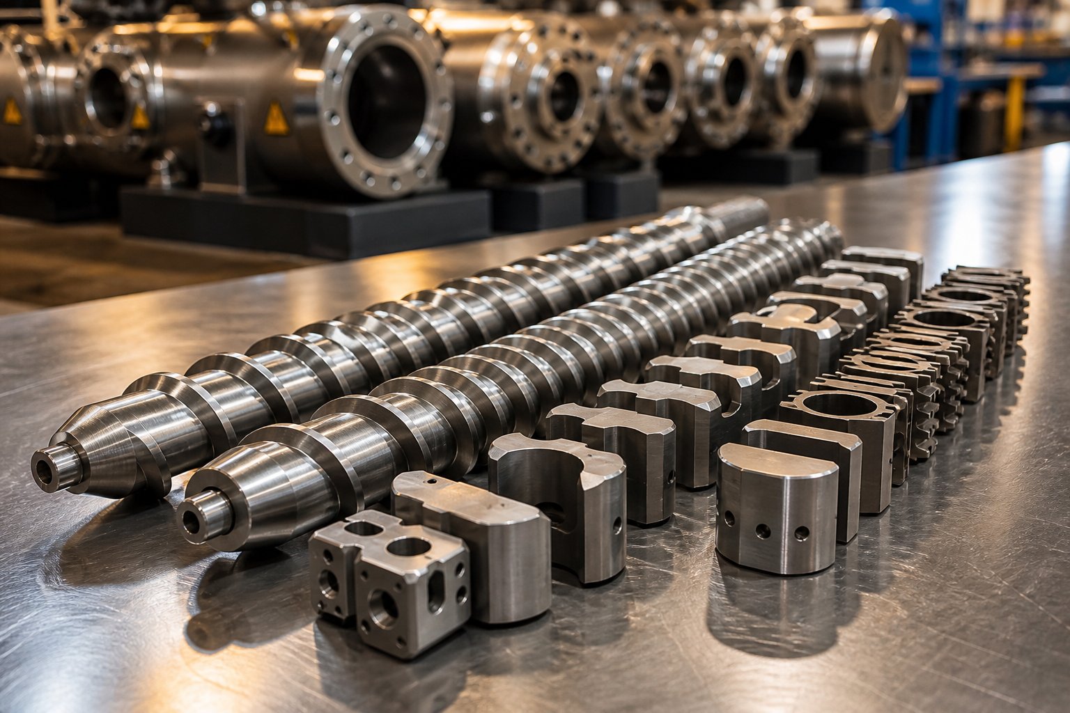
Imagine two interlocking screws rotating inside a barrel, each one lined with interchangeable segments that can be swapped, reordered, and reconfigured to transform raw polymer into a finished compound. That modular flexibility is exactly what makes twin screw extruder screw design so powerful — and so easy to get wrong.
Defining Twin Screw Extruder Screw Design
So what is twin screw extruder screw design, exactly? At its core, it is a discipline that blends engineering precision with process intuition.
Twin screw extruder screw design is the deliberate selection, sequencing, and configuration of modular screw elements along an extruder shaft to achieve specific processing objectives — including conveying, melting, mixing, and devolatilization.
This is fundamentally different from single screw systems, where the screw is typically machined as a single piece with fixed geometry. Twin screw extruder modular screw elements — conveying segments, kneading blocks, toothed mixers, reverse elements — can be assembled in countless combinations on a splined shaft. As NC State Extension highlights, the arrangement of these elements depends entirely on the process and material, and no gold standard exists for a universal screw profile because every material exhibits unique flow properties.
That modularity is the twin screw vs single screw design difference that matters most. It turns the screw profile into a programmable processing tool rather than a fixed hardware constraint.
Why Screw Design Is the Most Critical Variable in Extrusion
You can adjust barrel temperature, feed rate, and screw speed from a control panel. Those are process parameters — dials you turn during a production run. The screw profile, however, is something else entirely. It defines the fundamental capability envelope of the process. It dictates what shear rates are physically achievable, what residence times are possible, and what mixing intensities the machine can deliver. Change a temperature setpoint and you nudge the process. Change the screw configuration and you redefine what the process can do.
Think of twin screw extruder screw profile basics this way: the profile is the hardware architecture, and everything else is software running on top of it.
How This Resource Differs from Existing References
Most available resources fall into one of two camps. Academic publications explain screw terminology and mixing theory with rigor but stop short of practical design guidance. Industry articles offer scattered tips — useful fragments, but rarely connected into a coherent decision-making framework. This article bridges that gap. Every section ahead translates geometric parameters, element types, and process interactions into choices you can act on, from initial profile concept through validated production.
The journey starts where every screw profile starts: with the geometry of the elements themselves.
Core Screw Geometry Parameters That Drive Performance
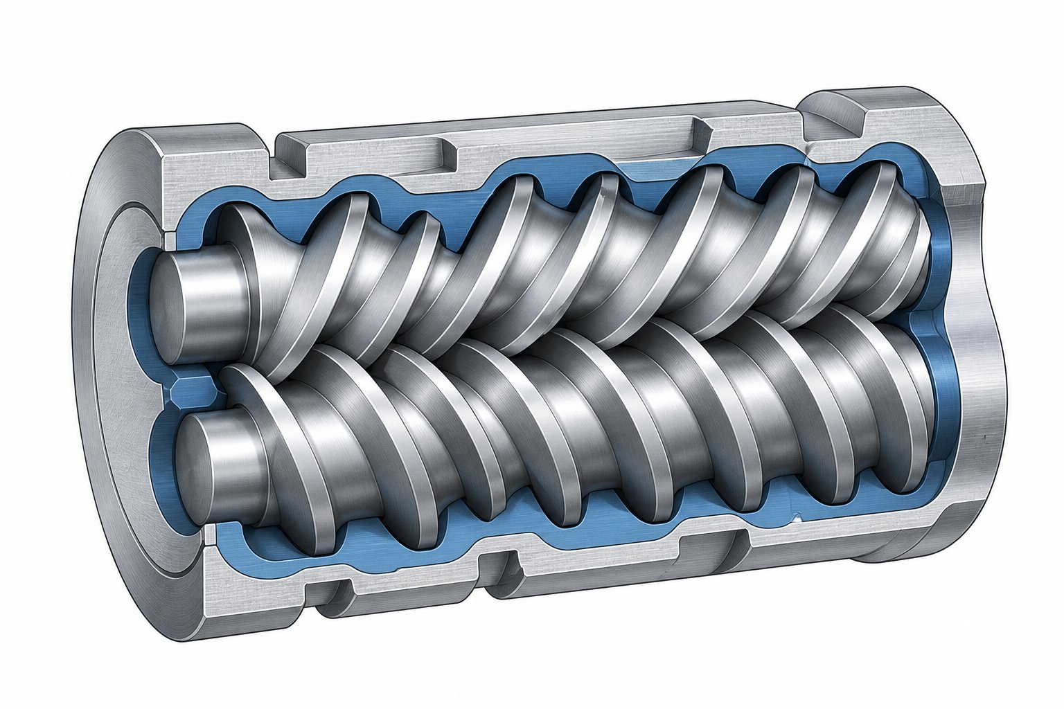
Every screw element you slide onto a splined shaft carries a set of geometric dimensions baked into its design. These dimensions — not the brand name, not the steel grade — are what ultimately determine how screw geometry affects extrusion performance. Three parameters sit at the foundation of every element selection decision: the OD/ID ratio, the pitch-lead-helix angle relationship, and flight depth. Understanding each one gives you predictive power over shear, throughput, and mixing quality before the extruder ever starts turning.
OD/ID Ratio and Its Effect on Free Volume and Shear
The outer-diameter-to-inner-diameter ratio is arguably the most fundamental geometric parameter in twin screw extruder screw design. It describes the relationship between the outermost tip of the screw flight (OD) and the root diameter at the bottom of the channel (ID). This single ratio controls two things simultaneously: the available free volume inside the barrel and the shear intensity the material experiences.
A high OD/ID ratio — say, in the range of 1.55 to 1.66 — produces deeper channels. More channel depth means more free volume per unit length, which translates to higher throughput capacity and lower shear rates. These geometries suit processes where gentle handling matters, such as compounding heat-sensitive polymers or incorporating long glass fibers that break under excessive shear.
A low OD/ID ratio — typically between 1.22 and 1.40 — creates shallow channels. Less depth means less free volume but dramatically higher shear intensity. The material gets squeezed through a tighter gap, generating more viscous dissipation and more aggressive mixing. This is where you land when you need to break agglomerates, disperse nanofillers, or drive reactive extrusion processes that depend on intensive mechanical energy input.
The table below maps these relationships in a scannable format:
| OD/ID Ratio Range | Relative Free Volume | Relative Shear Rate | Typical Application Suitability |
|---|---|---|---|
| 1.22 – 1.40 | Low | High | High-shear compounding, reactive extrusion, nanofiller dispersion |
| 1.40 – 1.55 | Medium | Medium | General-purpose compounding, pigment dispersion, filled systems |
| 1.55 – 1.66 | High | Low | Heat-sensitive polymers, fiber-reinforced compounds, high-throughput blending |
You'll notice the trade-off is inherent and unavoidable: increasing free volume always comes at the cost of reduced shear, and vice versa. The OD/ID ratio is fixed by the extruder platform itself, so this decision is locked in at the machine selection stage — long before you start arranging individual elements on the shaft.
Pitch, Lead, and Helix Angle Relationships
If OD/ID ratio defines the cross-sectional character of the screw, pitch and lead define its longitudinal behavior — how quickly material moves along the barrel axis.
Pitch is the axial distance covered by one full flight turn. Lead is the axial distance the material advances per single revolution of the screw. For a single-flighted element, pitch and lead are identical. For a double-flighted element (the standard in most co-rotating twin screw systems), the lead equals twice the pitch because two flights share the circumference.
The helix angle connects these linear dimensions to the rotational geometry. It describes the angle between the flight and a plane perpendicular to the screw axis. A steeper helix angle, driven by a larger pitch, increases the down-channel velocity component — boosting conveying capacity while reducing the local fill level. A shallower helix angle slows the forward movement of material, increasing residence time and promoting more interaction between the melt and the barrel wall.
Research on average shear rates in corotating twin screw elements demonstrates how these geometric relationships directly feed into shear rate calculations. The barrel velocity component along the channel, V cos θ (where θ is the helix angle), appears directly in the drag-flow shear rate expression. This means changing pitch doesn't just affect conveying — it simultaneously alters the shear field across the entire channel cross-section.
In practical terms, screw element catalogs reflect this through standardized pitch designations. NC State Extension's element nomenclature illustrates the pattern clearly: an SK 40/40 element with its larger pitch moves a larger bulk of material than an SE 20/20 element, which has a smaller pitch designed to compress and meter melt toward the die. Conveying ability decreases with decreasing pitch — a straightforward relationship that becomes a powerful design lever when you're sequencing elements along the barrel.
Flight Depth and Channel Geometry
Flight depth — the radial distance from the tip of the flight down to the screw root — directly controls the shear rate gradient across the channel. Imagine the barrel wall as a moving surface and the screw root as a stationary one. The velocity difference between these two surfaces, divided by the channel depth, gives you the fundamental drag-flow shear rate. The classic approximation for average shear rate in a screw channel expresses this as 2πNR / 60h, where N is the screw speed in rpm, R is the screw radius, and h is the channel depth.
Shallow channels produce a steep velocity gradient across a short distance. The shear field is relatively uniform, and every fluid element passing through that channel experiences similar shear history. This uniformity matters when you need consistent dispersion — breaking every agglomerate to the same degree, for instance.
Deep channels create a more complex picture. The velocity gradient is spread across a larger distance, and the shear rate near the screw root can be dramatically lower than the shear rate near the barrel wall. This non-uniformity introduces velocity gradients that affect mixing quality: some portions of the melt stream see high shear while others coast through with minimal deformation. For distributive mixing applications — where you want to spread a minor component evenly without necessarily breaking it down — this can actually be advantageous. For dispersive mixing, it's a liability.
Channel width, the space between adjacent flights, adds another layer. As NC State's technical overview notes, decreasing either channel depth or width increases shear input. Narrower channels restrict flow and force material through tighter gaps, amplifying the shear effect beyond what depth alone would predict.
These three geometric parameters — OD/ID ratio, pitch-lead-helix angle, and flight depth — don't operate in isolation. They interact as a system, and the same screw element catalog number carries all three embedded in its design. The real skill lies in understanding how these parameters combine differently across co-rotating and counter-rotating architectures, where intermeshing geometry adds yet another dimension to the design equation.
Co-Rotating vs Counter-Rotating Twin Screw Design Differences
Two screws spinning inside a barrel can rotate in the same direction or in opposite directions. That single distinction — co-rotating versus counter-rotating — reshapes the entire intermeshing geometry, rewrites the rules for element selection, and ultimately determines which processing tasks the extruder can handle well. Yet most technical resources treat this as a footnote rather than the foundational architectural decision it truly is.
How Intermeshing Geometry Differs Between Architectures
Picture two screws turning the same way, their flights meshing tightly as they spin. In a co-rotating intermeshing design, the flight tip of one screw continuously sweeps the channel of the other. This self-wiping action means material cannot stagnate in any channel — it gets pushed forward, transferred between screws, and constantly renewed at the barrel surface. Dead zones simply don't form, which is critical when you're processing thermally sensitive polymers that degrade if left sitting too long in a hot zone.
Counter-rotating intermeshing screws create an entirely different flow field. Because the screws turn toward each other at the top (or bottom, depending on orientation), the material gets trapped in enclosed, C-shaped chambers between the flights. These chambers act like tiny positive-displacement pumps — excellent for building pressure and conveying material forward in a controlled, predictable manner. The trade-off? That enclosed geometry limits how much the melt can transfer between screws, restricting mixing flexibility compared to the open, self-wiping intermeshing screw design of co-rotating systems.
The table below highlights how these architectural differences play out across key performance dimensions:
| Performance Dimension | Co-Rotating Intermeshing | Counter-Rotating Intermeshing |
|---|---|---|
| Self-Wiping Capability | Fully self-wiping; eliminates dead zones | Limited; enclosed C-chambers can trap material |
| Available Element Types | Extensive: conveying, kneading blocks, TME, ZME, SME, reverse elements | Narrower: primarily conveying elements with simpler mixing geometries |
| Mixing Intensity Range | Wide — from gentle distributive to aggressive dispersive | Moderate — primarily distributive and low-shear mixing |
| Pressure Generation | Moderate; relies on restrictive elements and die resistance | High; positive displacement provides inherent pressure build-up |
| Typical Throughput Range | High; scalable across wide operating windows | Moderate; throughput more tightly coupled to screw speed |
| Primary Applications | Compounding, reactive extrusion, devolatilization | PVC profile extrusion, calendering feed, gentle conveying |
You'll notice the contrast is stark. Co-rotating systems trade some pressure-building efficiency for vastly superior mixing flexibility. Counter-rotating systems sacrifice mixing range to gain the kind of controlled, gentle positive displacement that certain materials absolutely require.
Screw Element Availability and Configuration Flexibility
This architectural split has a direct consequence that shapes every screw profile you'll ever build: the library of available elements is dramatically different between the two platforms.
Co-rotating twin screw element types span an enormous range. You can choose from conveying elements in multiple pitches — from aggressive, high-pitch forwarding segments to tight, low-pitch metering sections. Kneading blocks come in virtually every stagger angle from 30 degrees through 90 degrees, plus reverse configurations. Beyond kneading blocks, specialized distributive mixing elements like toothed mixing elements (TME/ZME), screw mixing elements (SME), and gear-type mixers offer ways to split and recombine melt streams without the shear penalty of traditional kneading. Reverse-pitch conveying elements and neutral kneading blocks provide flow restriction for building melt seals. This extensive toolkit is what makes co-rotating extruders the most common setup for compounding applications where product consistency and formulation complexity demand maximum configurability.
Counter-rotating designs work from a much smaller menu. The enclosed chamber geometry constrains the types of elements that can function effectively. Conveying elements remain the primary building block, and mixing geometries tend to be simpler — often relying on modifications to flight geometry or basic barrier designs rather than the elaborate kneading block and specialty mixer combinations available on co-rotating platforms. This isn't necessarily a disadvantage for the right application, but it does mean counter-rotating profiles offer fewer degrees of freedom when you're trying to fine-tune shear intensity, distributive mixing quality, or residence time distribution independently.
When to Choose Each Architecture
So how do you decide? The choice between co-rotating and counter-rotating comes down to matching the machine's inherent strengths to your processing objectives.
Choose co-rotating when your process demands intensive or highly customizable mixing. Compounding engineering plastics with mineral fillers, dispersing pigments into masterbatch, running reactive extrusion chemistry, or performing multi-stage devolatilization — all of these benefit from the wide element library, self-wiping action, and broad operating window that co-rotating systems provide. If your formulation is complex or likely to evolve over time, the configurability of a co-rotating platform protects your investment.
Choose counter-rotating when gentle, positive-displacement conveying is the priority. Counter-rotating twin screw PVC extrusion is the classic example — PVC's thermal sensitivity and narrow processing window demand low shear and precise pressure control, both natural strengths of the counter-rotating architecture. Calendering feed applications, where consistent melt delivery matters more than mixing intensity, also favor this design. Any scenario where the material needs to move forward predictably without being subjected to the aggressive inter-screw transfer of a co-rotating system points toward counter-rotating.
The architecture decision locks in your element library and your mixing capability ceiling. It's a choice you make once and live with for the life of the machine. Everything that follows — the specific elements you select, the kneading block angles you specify, the zone-by-zone configuration strategy you build — plays out within the boundaries that architecture sets.
Screw Elements and Kneading Block Configuration Strategies
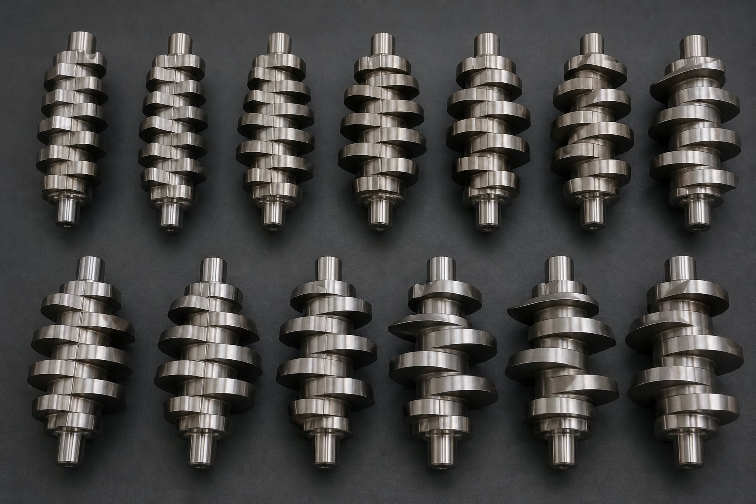
Your element library is set by the extruder architecture. Your processing outcome is set by what you actually do with that library. Every screw profile, regardless of application, is assembled from three fundamental categories of modular elements: conveying elements that move material forward (or backward), kneading blocks that deliver shear and mixing, and specialty distributive mixing elements that split and recombine melt streams with minimal thermal impact. Selecting the right element from each category — and sequencing them in the right order — is where twin screw extruder screw design shifts from theory to practice.
Conveying Elements and Their Design Variables
Conveying elements are the backbone of every screw profile. They occupy more barrel length than any other element type, and their job is deceptively simple: transport material from one functional zone to the next. The real design leverage comes from how you vary their pitch.
Most co-rotating systems use double-flighted conveying elements as the default. Two flights share the circumference, producing a self-wiping geometry that prevents material stagnation. Single-flighted designs exist for specific situations — they provide deeper channels and more free volume per revolution, useful when you need to handle bulky feedstocks or maximize throughput in starve-fed zones — but double-flighted elements dominate because they offer tighter intermeshing and better self-cleaning action.
Twin screw extruder conveying element pitch is the primary variable you control. A high-pitch element — say, 2.0D (where D is the bore diameter) — moves material aggressively forward, creating low fill levels and short local residence times. This is your go-to choice for feed zones where you need to pull material away from the hopper quickly, or for vent zones where low fill promotes efficient gas escape. A 1.5D pitch offers a moderate balance: decent conveying with slightly increased fill. Drop to a 1.0D pitch and conveying slows considerably — the material spends more time in the channel, fill levels rise, and the element begins to function more like a metering device than a transporter.
Then there are reverse-pitch conveying elements, which flip the helix direction entirely. Instead of pushing material forward, they pump it backward. Why would you want that? Because reverse elements create a local dam in the flow, forcing material to build up upstream. This generates pressure, increases fill level in the preceding zone, and — critically — can create a melt seal that prevents gas or vacuum from migrating along the barrel. You'll find reverse elements positioned just upstream of vent ports in nearly every devolatilization screw profile.
Kneading Block Stagger Angles and Mixing Intensity
If conveying elements are the workhorse, kneading blocks are the engine of every mixing zone. A kneading block is composed of individual disc-shaped lobes stacked along the shaft at a specific angular offset — the stagger angle. That angle is the single most influential variable in determining what kind of mixing the block delivers, how much shear it imposes, and how much it restricts forward flow.
The main parameters that affect kneading block performance are the stagger angle, the number of discs in the block, and the thickness of each individual disc. Thicker discs produce greater shear and less distributive mixing, while thinner discs reduce shear and increase the splitting and recombining action that drives distributive mixing. Most standard kneading blocks use double-lobed (two-flight) disc geometry, though three-lobed variants exist and can generate higher shear stresses due to tighter clearances between the lobes and the barrel wall.
Here is a kneading block stagger angle selection guide covering the standard configurations you'll encounter:
| Stagger Angle | Mixing Type | Intensity Level | Melt Temperature Impact | Recommended Use Case |
|---|---|---|---|---|
| 30° (forward) | Primarily distributive | Low | Minimal increase | Gentle blending, color incorporation, heat-sensitive formulations |
| 45° (forward) | Balanced distributive and dispersive | Moderate | Moderate increase | General compounding, polymer blends, standard filler incorporation |
| 60° (forward) | Primarily dispersive with reduced conveying | High | Significant increase | Pigment dispersion, breaking soft agglomerates, intensive blending |
| 90° (neutral) | Maximum dispersive | Highest | Substantial increase | Breaking hard agglomerates, nanofiller dispersion, high-shear compounding |
| Reverse (backward) | Extreme flow restriction | Very high | Substantial increase | Creating melt seals for devolatilization, maximum pressure build-up |
The logic behind this kneading block 30 45 60 90 degree comparison is straightforward once you see the pattern. At 30 degrees, each successive disc is only slightly offset from the previous one, preserving a strong forward-conveying component. Material moves through the block relatively quickly, experiencing repeated splitting and recombining — classic distributive mixing — without spending enough time in the high-shear zones to overheat. At 45 degrees, the conveying component weakens and the mixing component strengthens, creating a balanced profile that handles most general compounding tasks well.
Push to 60 degrees and the forward-conveying action drops sharply. Material lingers longer in the intermeshing region, and the shear forces escalate. The trade-off becomes real here: you get better dispersion, but melt temperature climbs noticeably. At 90 degrees, forward conveying essentially disappears — the block becomes neutral, neither pushing material forward nor backward. Every disc presents a perpendicular face to the flow, forcing material through the narrowest clearances at maximum shear. 3D CFD research at Paderborn University confirmed that 90-degree kneading blocks achieve better distributive mixing quality (lower MQ index values) than 45-degree blocks under identical processing conditions, though the difference in dispersive shear stress was less pronounced than expected.
Reverse kneading blocks take the concept further by angling the discs in the opposite rotational direction. The reverse kneading block melt seal function works exactly like a reverse conveying element — it pumps material backward, creating a high-pressure zone upstream. This is essential directly before vacuum vent ports, where you need a complete melt seal to prevent atmospheric leakage into the vacuum system. The combination of backward pumping and intense shear makes reverse kneading blocks extremely restrictive, so they should be used sparingly and positioned deliberately.
Specialty Distributive Mixing Elements
Kneading blocks are powerful, but they come with an inherent penalty: shear generates heat. For thermally sensitive polymers — think PVC compounds, certain biopolymers, or shear-degradable blends — that heat penalty can be a dealbreaker. This is where distributive mixing elements like TME, ZME, and SME earn their place in the profile.
Toothed mixing elements (often designated TME or ZME depending on the manufacturer) feature rows of tooth-like protrusions arranged along the element surface. Instead of shearing material through a narrow gap like a kneading disc, these teeth repeatedly divide the melt stream into smaller streams and then recombine them. Imagine a river splitting around a series of rocks and rejoining downstream — each split-and-recombine cycle redistributes minor components (pigments, additives, fine fillers) more uniformly throughout the melt without the intense viscous dissipation of a kneading block. The research from Paderborn University's particle tracking study found that ZME elements outperformed all kneading block configurations tested for distributive mixing quality. The ZME also generated higher and more uniform maximum shear stresses across tracked particles compared to kneading blocks, making it effective for dispersive mixing as well — a finding that challenges the conventional assumption that kneading blocks are always superior for dispersion.
Screw mixing elements (SME) take a different geometric approach, using interrupted flights or slotted channels to create cross-channel flow that enhances distribution. Gear-type mixers, with interlocking tooth profiles, provide yet another path to splitting and recombining flow streams. Each design variant offers a slightly different balance between distributive efficiency, pressure drop, and residence time impact.
The practical takeaway? When your formulation demands uniform filler distribution without thermal damage — high-loading CaCO3 masterbatch, for instance, or color-critical applications where pigment distribution must be flawless — specialty distributive mixing elements often outperform kneading blocks on a quality-per-degree-of-temperature-rise basis. They are not replacements for kneading blocks in every scenario, but they fill a critical gap where shear-sensitive mixing quality is the priority.
Choosing the right elements is only half the equation. How those elements interact with the barrel's length — and how many functional zones you can fit between the feed throat and the die — depends on a system-level parameter that shapes everything else: the L/D ratio.
How L/D Ratio Selection Shapes Processing Outcomes
Every element you choose — conveying segments, kneading blocks, distributive mixers — needs physical space on the barrel to do its job. The twin screw extruder barrel length to diameter ratio, commonly written as L/D, is the system-level parameter that determines exactly how much space you have to work with. It sets the upper limit on how many functional zones you can fit between the feed throat and the die, and that limit ripples through every aspect of processing capability: mixing quality, thermal exposure, venting capacity, and throughput flexibility.
Sounds abstract? Think of it this way. A short barrel is like a small kitchen — you can cook a simple meal, but you don't have counter space for prep, sauteeing, plating, and cleanup all happening simultaneously. A long barrel gives you a professional kitchen with dedicated stations for each task. The food (your polymer) moves through each station in sequence, and the quality of the final dish depends on having enough stations to accomplish everything the recipe demands.
What L/D Ratio Means for Processing Capability
The L/D ratio is calculated by dividing the total processing length of the barrel by its bore diameter. An extruder with a 40 mm bore diameter and a 1,600 mm barrel length has an L/D of 40:1. Simple math, but the implications are profound.
Each functional zone along the barrel — feeding, melting, mixing, venting, pressure building — consumes a certain number of diameters in length. A melting zone built from kneading blocks might occupy 4D to 6D. A devolatilization section with a melt seal, low-fill conveying under vacuum, and downstream re-compression could consume 6D to 10D. Add a side feeder port for filler incorporation, and that demands another 4D to 6D for the feeding and downstream mixing zones. The math adds up quickly, and a shorter barrel simply cannot accommodate all of these zones simultaneously.
Twin screw extruder L/D ratio selection, then, is really a question about how many processing tasks you need the machine to perform in a single pass. The table below maps common L/D ratios against the processing capability they unlock:
| L/D Ratio | Typical Functional Zone Count | Relative Residence Time | Mixing Capability | Primary Application Suitability |
|---|---|---|---|---|
| 25:1 | 2 – 3 | Short | Basic — single mixing zone | Simple blending, color masterbatch, low-complexity formulations |
| 32:1 | 3 – 4 | Short to moderate | Moderate — one or two mixing stages | Standard masterbatch, basic filled compounds, thermally sensitive materials |
| 40:1 | 4 – 5 | Moderate | Good — multiple mixing and venting zones | Engineering plastics compounding, mineral-filled systems, single-stage devolatilization |
| 48:1 | 5 – 7 | Moderate to long | High — distributed mixing with multi-stage venting | Reactive extrusion, high-filler compounds, multi-stage devolatilization |
| 52:1 | 6 – 8 | Long | Very high — extensive zone sequencing possible | Complex reactive processes, simultaneous devolatilization and downstream mixing |
You'll notice the pattern immediately: each step up in L/D unlocks additional functional zones. A 25:1 machine can feed, melt, mix, and push material out — but there's no room left for a dedicated vent section or a second mixing stage. By 48:1, you have enough barrel real estate to include multiple mixing zones, side feeding, and two or even three vent ports — the kind of configuration that reactive extrusion and highly filled compounds demand.
How L/D Ratio Impacts Residence Time Distribution
Longer barrels inherently increase mean residence time — material simply spends more seconds traveling from feed throat to die. For many compounding applications, that's perfectly acceptable and even beneficial, because more time means more opportunity for mixing and heat transfer to complete their work.
The subtler and often more important effect is on residence time distribution (RTD) — the spread between the fastest and slowest material particles passing through the extruder. A narrow RTD means every particle experiences nearly the same thermal and shear history. A broad RTD means some particles race through quickly while others linger, creating inconsistencies in the final product.
Why does this matter? Consider reactive extrusion, where a chemical reaction — grafting, crosslinking, chain extension — progresses as the material moves down the barrel. If the RTD is broad, some material reacts for the correct duration while other portions either under-react (producing ungrafted polymer) or over-react (causing degradation or gel formation). The best L/D ratio for reactive extrusion is typically 48:1 or longer, but simply extending the barrel doesn't automatically tighten the RTD. Careful element selection is equally critical: excessive use of highly restrictive elements like 90-degree kneading blocks can create recirculation zones that broaden residence time spread, even on a long-barrel machine. Distributive mixing elements and well-placed conveying sections help maintain a more uniform plug-flow character that keeps the RTD tight.
The L/D ratio effect on residence time distribution is therefore a two-factor problem. The barrel length sets the mean residence time, while the screw profile within that barrel determines how tightly individual particles cluster around that mean. Getting one right without the other leads to suboptimal results.
Selecting L/D Ratio Based on Processing Objectives
With the relationship between barrel length, zone capacity, and residence time behavior clear, practical selection guidance becomes straightforward. Match your L/D to the complexity of what you're asking the extruder to accomplish:
- Shorter L/D (25:1 – 32:1): Best for simple blending and masterbatch production where the formulation is straightforward — a carrier resin plus pigment or a basic additive package. These processes need a single melting zone and one mixing stage. Shorter barrels also suit thermally sensitive materials that degrade with extended heat exposure, as they minimize the time the polymer spends at elevated temperatures.
- Medium L/D (36:1 – 44:1): The workhorse range for standard compounding of engineering plastics, mineral-filled systems, glass fiber reinforcement, and flame-retardant formulations. Medium-length barrels provide enough room for a proper melting zone, one or two mixing stages (often including a side feeder section for downstream filler addition), and at least one atmospheric or vacuum vent. Most general-purpose compounding lines fall in this range because it balances processing capability against capital cost and floor space.
- Longer L/D (48:1 – 52:1): Reserved for the most demanding applications. Reactive extrusion processes that require controlled reaction time across a distributed mixing profile need this kind of barrel length. Multi-stage devolatilization — removing moisture, solvents, or reaction byproducts through two or three sequential vent ports, each with its own melt seal — physically cannot fit on shorter machines. High-filler-loading compounds that require gentle but extensive distributive mixing downstream of a side feeder also benefit from the extra barrel real estate, particularly when the formulation demands both thorough mixing and a final venting step before the die.
One practical consideration that's easy to overlook: a longer barrel is not always better. Every additional unit of L/D adds cost — more barrel sections, more heating and cooling zones, more screw elements to purchase and maintain, and a longer machine footprint on the factory floor. If your process only requires 32:1 of functional capability, buying a 48:1 machine wastes capital and creates unnecessary residence time that can actually harm product quality in heat-sensitive formulations. The right L/D ratio is always the shortest one that fits all the functional zones your process requires, with a modest margin for future flexibility.
Selecting the right barrel length and distributing functional zones along it establishes the macro architecture of your screw profile. But the screw profile doesn't operate in isolation — it interacts dynamically with feed rate, screw speed, and the energy balance of the entire system. Those interactions introduce a set of fundamental trade-offs that every profile designer must navigate.
Process-Design Interactions and Fundamental Trade-Offs
A screw profile defines what your extruder can do. Feed rate, screw speed, and barrel temperatures determine what it actually does on any given run. The hardware sets the boundary conditions — the envelope of achievable shear rates, residence times, and mixing intensities — while operating parameters position the process somewhere inside that envelope. Misunderstanding this relationship is one of the most common sources of frustration in twin screw extruder process parameter optimization: engineers tweak setpoints endlessly when the real limitation is baked into the screw configuration itself, or they redesign an entire profile when a simple feed rate adjustment would solve the problem.
Separating what belongs to the screw from what belongs to the operating window is the key to efficient troubleshooting and rational process development.
Specific Energy Input as a Unifying Metric
If you could distill the entire interaction between screw design and process parameters into a single number, it would be specific energy input. SEI, measured in kWh/kg, captures how much mechanical energy the extruder delivers per kilogram of material processed. It is calculated from motor power draw divided by mass throughput, and it reflects the combined effect of screw speed, feed rate, and — critically — the screw profile's shear characteristics.
Why does this matter so much? Because two very different combinations of hardware and operating parameters can produce the same SEI while delivering completely different outcomes. Imagine a high-shear screw profile — loaded with 60-degree and 90-degree kneading blocks — running at moderate RPM. It delivers a certain SEI. A milder profile with 30-degree and 45-degree kneading blocks, pushed to significantly higher RPM, could match that same SEI value. The energy input per kilogram is identical on paper, but the way that energy enters the melt differs dramatically.
The aggressive profile at moderate speed delivers energy through intense, localized shear zones. Melt temperature spikes in the kneading sections, then partially recovers in downstream conveying zones. The mild profile at high speed spreads energy input more evenly along the barrel, with lower peak shear rates but more continuous viscous dissipation. The result? Different melt temperature profiles, different residence time distributions, and different mixing quality — even at the same SEI. This is precisely the mixing intensity vs melt temperature trade-off that makes twin screw extrusion more nuanced than simple energy balance calculations suggest.
Tracking SEI across trials gives you a powerful diagnostic lens. If product quality degrades when you scale up, comparing SEI between pilot and production machines immediately tells you whether the total energy input shifted or whether it's a distribution problem. Specific energy input in twin screw extrusion functions as a universal process fingerprint — not a perfect predictor of outcomes, but the single best starting point for cross-machine comparison.
Fill Level, Starve Feeding, and Screw Design Interaction
Here's something that surprises engineers coming from single screw backgrounds: co-rotating twin screw extruders are inherently starve-fed. The feed rate is set independently from the screw speed, and the screw almost always has more drag-flow conveying capacity than the feeder supplies. The result is that most of the barrel runs partially filled — material tumbles and slides through channels that aren't completely packed with melt.
This starve-fed nature creates a direct, dynamic link between operating parameters and local processing conditions. The ratio of feed rate to screw speed determines the degree of fill in each barrel zone. Increase screw speed at constant feed rate, and fill levels drop — material spends less time in every zone, residence time shortens, and the effective mixing intensity in partially filled kneading blocks decreases because the elements aren't fully engaged with melt. Increase feed rate at constant speed, and fill levels rise — residence time extends, kneading blocks work harder against a fuller melt bed, and pressure profiles shift upward throughout the barrel.
The screw profile shapes this interaction in a fundamental way. Restrictive elements — kneading blocks with high stagger angles, reverse conveying segments, neutral kneading blocks — act as dams in the flow. Material backs up behind these restrictions, forcing the upstream zone to run at higher fill levels regardless of the nominal feed-rate-to-speed ratio. A fully filled zone upstream of a kneading block generates continuous viscous shear and more efficient heat transfer, while a partially filled conveying section downstream of that same block allows gas escape at a vent port.
This is why starve feeding and screw fill level interaction cannot be treated as an operating parameter problem alone. The screw design dictates the drag-flow capacity at any given RPM and determines where restrictions create localized full-fill conditions. The operating parameters then position the process within those hardware-defined constraints. Change the screw profile, and the same feed-rate-to-speed ratio produces an entirely different fill level distribution along the barrel.
The Fundamental Trade-Offs in Screw Profile Design
Every decision you make in screw profile design activates a tension between competing objectives. Push one variable in a favorable direction, and at least one other variable pushes back. These trade-offs aren't problems to solve — they're constraints to navigate. Experienced process engineers don't try to eliminate them; they find the best achievable compromise for the specific material and production target at hand.
The core trade-offs that surface in virtually every profile design project include:
- Mixing intensity vs. melt temperature rise — More aggressive kneading blocks deliver better dispersion and distribution, but every increment of shear converts mechanical energy into heat. Thermally sensitive materials impose a hard ceiling on how much mixing intensity you can apply before degradation begins.
- Throughput capacity vs. residence time — Higher feed rates and larger pitch conveying elements maximize output, but they reduce the time material spends in mixing and devolatilization zones. If mixing quality or volatile removal is insufficient, pushing throughput further won't help — it makes both worse.
- Dispersive mixing vs. distributive mixing — High-stagger kneading blocks excel at breaking agglomerates but impose severe shear and temperature penalties. Distributive elements spread components uniformly with less thermal damage but cannot fracture tightly bonded particle clusters. Most profiles require both, carefully zoned along the barrel.
- Shear intensity vs. material degradation risk — This goes beyond temperature alone. Excessive shear can mechanically degrade polymer chains, break reinforcing fibers, damage platelet morphology in barrier compounds, or prematurely activate reactive additives — even when bulk melt temperature appears acceptable.
- Pressure generation vs. energy input — Building die pressure requires restrictive elements or tight-pitch metering sections, both of which convert motor torque into viscous heating. The pressure needed for stable die flow must be weighed against the thermal cost of generating it.
Optimizing twin screw extruder screw design is never about maximizing a single parameter — it is about finding the best compromise for the specific material system, formulation requirements, and production objectives.
These trade-offs don't exist in isolation. Adjusting one cascades through the others. Lengthen a kneading block to improve dispersion, and melt temperature rises, which may force you to reduce screw speed, which lowers fill level, which reduces mixing effectiveness — partially undoing the original change. Recognizing these interdependencies is what separates methodical screw profile development from trial-and-error tinkering.
The trade-offs also shift depending on what you're processing. A glass-fiber-reinforced PA6 demands a completely different compromise balance than a 60% CaCO3-filled polyolefin or a moisture-sensitive biopolymer. The material itself — its viscosity, thermal limits, filler characteristics, and moisture content — dictates which trade-offs dominate and how aggressively each one constrains the design space.
Matching Screw Design to Material Properties and Formulations
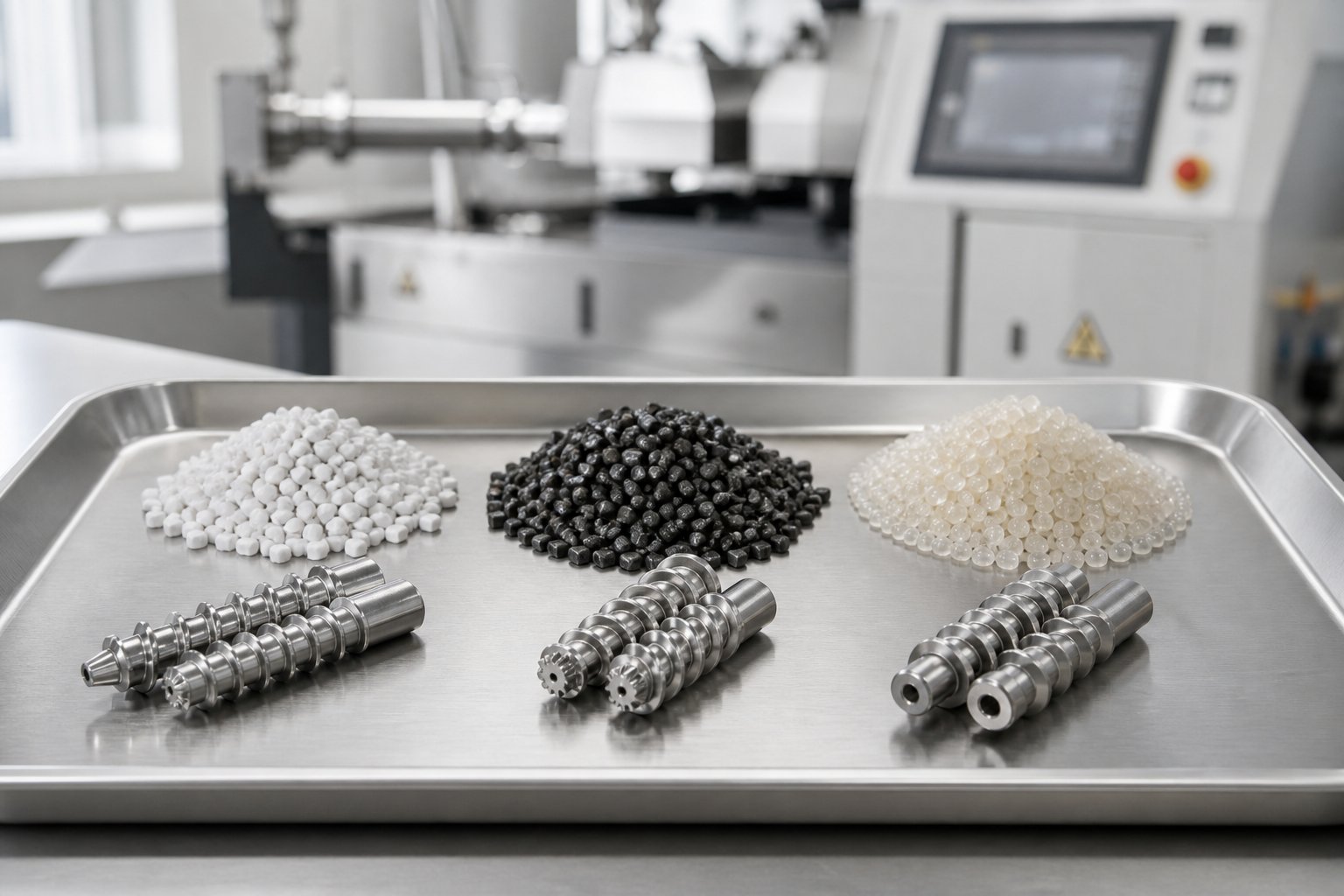
A 90-degree kneading block doesn't know whether it's shearing HDPE or PVC. It applies the same geometry-driven forces regardless of what flows through it. The material, however, responds very differently — and that response is what should drive every element selection decision. Screw design for thermally sensitive polymers looks nothing like a profile for mineral-filled polyolefins, and both differ dramatically from what glass fiber compounding demands. The material's viscosity, thermal stability, filler characteristics, and moisture content aren't secondary considerations layered on top of geometry — they're the primary inputs that geometry must serve.
How Melt Viscosity and Thermal Sensitivity Guide Element Selection
High-viscosity polymers resist flow. When you push a high-molecular-weight polyamide or HDPE through a twin screw extruder, the melt fights every restriction you place in its path. That resistance demands more aggressive melting and mixing elements — wider kneading blocks at 60-degree or 90-degree stagger angles, longer kneading sections, and potentially tighter-pitch conveying elements upstream to build the fill level needed to engage those blocks effectively. The polymer can absorb the shear energy without damage because its thermal stability window is wide enough to tolerate the resulting temperature rise.
Thermally sensitive materials flip that logic entirely. PVC is the textbook case — its high viscosity generates significant viscous dissipation under shear, yet its thermal degradation threshold sits dangerously close to its processing temperature. ANSYS Polyflow simulations of PVC in counter-rotating twin screw extruders illustrate this tension vividly: even at a modest 43 rpm, careful temperature management across kneading, compressing, and mixing sections was required to prevent degradation while still generating adequate pumping pressure. The barrel temperatures had to drop from 200 degrees C in the kneading zone to 160 degrees C in subsequent zones just to keep the melt stable.
The central tension in screw design for thermally sensitive polymers is the interplay between viscous dissipation and thermal degradation. Every joule of mechanical energy that enters the melt through shear raises the temperature. If the polymer's degradation ceiling is low, you hit that ceiling fast — forcing you toward gentler configurations with distributive mixing elements (TME, ZME) rather than high-stagger kneading blocks, shorter mixing zones, and larger-pitch conveying elements that minimize residence time in heated zones. Certain biopolymers and reactive PVC formulations push this constraint to its extreme, where even moderate kneading block sections can trigger discoloration or molecular breakdown.
The practical rule? Start with the material's thermal budget — the gap between its required processing temperature and its degradation onset — and let that budget dictate how much shear energy the profile is allowed to deliver.
Filler Loading, Fiber Length, and Screw Profile Adaptation
Fillers and reinforcements transform the design challenge. The polymer alone might tolerate aggressive mixing, but the filler often cannot — or it demands a kind of mixing the base resin wouldn't otherwise need. Three common scenarios illustrate how screw design for high filler loading compounds differs based on filler type:
- Mineral fillers at high loading (40-70% CaCO3): The priority is uniform distribution without overheating the carrier resin. Feed zones must be gentle — high-pitch conveying with large free volume to accommodate the bulk density of the filler-polymer blend. Downstream, strong distributive mixing elements spread the filler evenly. Kneading blocks in this context are tuned for distribution (30-degree to 45-degree stagger) rather than dispersion, because the particles don't require fracturing — they just need to be uniformly embedded in the melt matrix.
- Glass fiber compounds: Fiber length preservation is the dominant concern. Every high-shear element the fibers encounter snaps them shorter, and shorter fibers mean weaker parts. A twin screw extruder screw profile for glass fiber compounding typically introduces fibers through a downstream side feeder — well past the melting and primary mixing zones — followed by conveying-only elements with minimal kneading. Research at the University of Paderborn comparing three screw configurations for glass-fiber-reinforced polypropylene confirmed this directly: the configuration with kneading blocks and mixing elements after the fiber feed point (SC1) consistently produced the shortest fibers, while the conveying-only configuration (SC2) preserved significantly more fiber length across 20, 30, and 40 wt% glass fiber loadings. The fiber length decreased rapidly within the first 15 mm after fiber addition, dropping from 3 mm to 2 mm almost immediately — highlighting how critical those first few elements after the feed point truly are.
- Nanofillers (organoclays, carbon nanotubes, nano-silica): The opposite problem. These materials arrive as tightly bonded agglomerates that must be broken apart to achieve their reinforcement potential. High-intensity dispersive mixing — 60-degree and 90-degree kneading blocks, possibly repeated in multiple zones — is essential. Without sufficient shear to exfoliate or delaminate the agglomerates, the nanoparticles remain clumped, and the compound performs no better than a conventionally filled system.
You'll notice the pattern: the filler type, not the base polymer, often becomes the controlling factor in profile design for filled compounds. A polypropylene matrix can handle aggressive mixing, but the glass fibers in it cannot. The same polypropylene with nano-clay demands the most aggressive mixing available. Same resin, completely different screw profiles.
Moisture Content and Devolatilization Zone Design
Hygroscopic polymers — nylons, polycarbonate, PET, many biopolymers — absorb moisture from the atmosphere. If that moisture isn't removed before or during processing, it hydrolyzes polymer chains, causing molecular weight loss, poor mechanical properties, and surface defects in the finished product. Moisture-sensitive reactive extrusion processes face an even steeper challenge, where water generated as a reaction byproduct must be continuously stripped from the melt.
This is where devolatilization zone screw element configuration becomes a defining feature of the profile architecture. As Plastics Technology's practical guide to devolatilization explains, a typical vent zone consists of a partially filled screw section isolated between two melt-sealed regions. The upstream melt seal — created by reverse conveying elements or neutral (90-degree) kneading blocks — forces the screw to run completely full at that point, preventing vacuum from pulling backward along the barrel. Downstream, a similar seal (or the die itself) prevents vacuum leakage in the forward direction.
Between these seals, high-pitch conveying elements run at low fill levels under applied vacuum. The low fill maximizes exposed melt surface area, and the vacuum lowers the partial pressure of the volatile component, both of which accelerate mass transfer of moisture out of the melt. A practical rule of thumb: each vent stage can reduce volatile concentration by roughly an order of magnitude. A single vent might bring moisture from 0.2% down to 0.02%. Two sequential vent zones — each with its own upstream melt seal and vacuum port — can push residuals below 0.002%.
The number of vent ports and their positions tie directly back to L/D ratio and profile architecture. Each vent zone consumes 6D to 10D of barrel length (melt seal plus low-fill conveying plus downstream re-compression), so a machine with two or three vent stages needs a minimum of 40:1 to 48:1 L/D just to accommodate them alongside feeding, melting, and mixing zones. The design of each downstream seal is especially critical — if the restriction is too tight or too close to the vent opening, high throughput or low screw speed can cause melt to back up into the vent port, blocking the vacuum line and defeating the entire purpose of the zone.
Material properties, filler demands, and moisture management each impose their own constraints on the screw profile. The challenge — and the opportunity — lies in translating these material-driven requirements into specific zone-by-zone element sequences for real applications.
Application-Specific Screw Profile Design Strategies
Geometry parameters, element types, trade-offs, material constraints — all of these concepts gain their real meaning only when assembled into a complete, zone-by-zone screw profile targeting a specific production goal. A twin screw extruder screw profile for compounding a 50% CaCO3-filled polyolefin looks nothing like a reactive extrusion screw configuration design for grafting maleic anhydride onto polypropylene. Same machine platform, same element catalog, radically different arrangements. This section walks through how the principles covered so far translate into concrete profile strategies for the most common twin screw applications.
Compounding and Masterbatch Screw Profiles
Imagine you're setting up a line to produce a 60% mineral-filled polyethylene compound with a color masterbatch incorporated at the feed throat. The formulation demands thorough filler distribution, complete pigment dispersion, and a vacuum vent to strip residual moisture before the die. Here's how a masterbatch screw profile zone by zone layout typically comes together:
- Zone 1 — Solids Conveying (Feed Section): High-pitch conveying elements (1.5D to 2.0D pitch) grip the pellet-and-powder blend and move it away from the feed throat quickly. The goal here is preventing bridging and ensuring a steady, uninterrupted intake. Fill levels are deliberately kept low to avoid back-pressure toward the hopper.
- Zone 2 — Melting and Primary Mixing: The pitch transitions to moderate conveying elements (1.0D to 1.25D) to begin building fill level, followed by an aggressive kneading block section. For a compound requiring both pigment dispersion and resin melting, this zone typically uses 60-degree forward kneading blocks to deliver strong dispersive action, followed by a short section of 90-degree neutral blocks to break any remaining pigment agglomerates. Melt temperature rises significantly here — that's the price of effective dispersion in this zone.
- Zone 3 — Side Feeder and Filler Incorporation: A side stuffer introduces the mineral filler directly into the melt stream. Immediately upstream of the side feeder port, conveying elements run at low fill to create a zero-pressure zone that allows the side stuffer to push material into the barrel without resistance. Downstream, distributive mixing elements — toothed mixing elements (TME or ZME) or low-stagger 30-degree kneading blocks — spread the filler uniformly through the melt. The emphasis shifts entirely from dispersive to distributive here: the CaCO3 particles don't need to be fractured, just evenly embedded.
- Zone 4 — Devolatilization: A melt seal created by reverse conveying elements or a short neutral kneading block section isolates the upstream mixing zone from the vacuum port. High-pitch conveying elements (1.5D or higher) then run at low fill under vacuum, maximizing exposed melt surface area for efficient moisture removal.
- Zone 5 — Metering and Discharge: Tight-pitch conveying elements (0.75D to 1.0D) build stable die pressure. The goal is consistent volumetric flow to the pelletizing die, with enough compression to prevent surging but not so much restriction that melt temperature spikes at the exit.
This five-zone architecture handles most filled compound and masterbatch applications. The specific elements shift — glass fiber compounds replace the downstream kneading blocks with conveying-only sections to preserve fiber length, while carbon black masterbatch may double the dispersive mixing length in Zone 2 — but the zone logic stays consistent.
Reactive Extrusion and Devolatilization Profiles
Reactive extrusion flips several of the compounding assumptions. Instead of applying mixing energy in concentrated bursts, a reactive extrusion screw configuration design distributes mixing intensity across a much longer barrel — typically 48:1 L/D or greater — to control the reaction's progress as material moves from feed to die.
Why the emphasis on distribution rather than concentration? Because reactions are time-dependent. A grafting reaction, for example, needs a certain combination of temperature, shear exposure, and residence time to reach target conversion without over-reacting. Concentrate all the mixing into one aggressive kneading zone, and the reaction either completes too quickly (risking degradation and gel formation) or not at all (if the residence time in that single zone is too short). Spreading moderate-intensity mixing elements — 45-degree kneading blocks, distributive TME sections, and carefully spaced conveying zones — across 30 or more diameters of barrel length gives the reaction time to proceed uniformly through the melt.
Residence time distribution becomes the critical quality metric. As the research published in Chemical Engineering Science demonstrated through dynamical modeling of reactive extrusion in a co-rotating twin screw extruder, the RTD profile directly governs reaction extent and product consistency. A broad RTD means some material over-reacts while other portions under-react — producing an inconsistent product that fails specification checks. Tight RTD demands careful avoidance of recirculation zones: minimal use of 90-degree and reverse kneading blocks in the reaction zone, preference for forward-pumping distributive elements, and adequate conveying sections between mixing stages to maintain near-plug-flow character.
A devolatilization screw profile for a twin screw extruder demands its own architectural logic. Multi-stage devolatilization — removing solvents, moisture, or reaction byproducts through two or three sequential vacuum ports — requires alternating patterns of melt seal, low-fill vent section, and re-compression, repeated along the barrel. Each vent stage follows the same structural template:
- A restrictive element (reverse conveying or neutral kneading block) upstream to create a pressure dam and fully sealed melt plug
- An immediate transition to high-pitch, low-fill conveying under vacuum to maximize surface renewal
- A downstream transition back to moderate conveying that re-compresses the melt before the next stage or die
The challenge intensifies when reactive extrusion and devolatilization must coexist on the same barrel. A typical scenario: polymerization generates water as a condensation byproduct, and that water must be stripped continuously to drive the reaction forward. The profile needs to interleave reaction mixing zones with vent stages — a sequencing problem that frequently pushes L/D requirements to 52:1 and demands meticulous coordination between melt seal positions, vent port locations, and barrel temperature zones.
Getting Screw Profiles Right for Your Specific Process
The zone-by-zone strategies above provide frameworks, not finished blueprints. Every real application introduces variables that shift the balance: the specific polymer grade's melt flow index, the filler's particle size distribution and surface treatment, the target throughput rate on a particular machine class, the available torque at the target screw speed, and a dozen other factors that interact simultaneously.
Application-specific screw design requires integrating material data, processing objectives, and machine constraints into a single coherent configuration. Getting that integration right on the first or second iteration — rather than the fifth or tenth — depends on experience with the specific interdependencies between element geometry, process parameters, and material behavior. Some teams build this capability internally over years of systematic trials. Others accelerate the process by working with specialists who bring cross-application experience and detailed knowledge of element performance across multiple extruder platforms.
For teams that need screw geometry, material selection, and processing recommendations tailored to specific polymers and machine conditions, NANHAIYA's custom screw design services support extrusion engineers and production teams through this process. Their approach covers screw element recommendations, material-grade selections for wear and corrosion resistance, and configuration strategies matched to specific extruder platforms and output requirements — whether you're building a new compounding line from scratch or troubleshooting an existing profile that isn't delivering the dispersion or throughput you need.
Designing the right profile for a single machine is one challenge. Transferring that profile successfully from a lab-scale extruder to a full production platform — without losing the mixing quality, thermal control, and product consistency you validated at small scale — introduces an entirely different set of engineering problems.
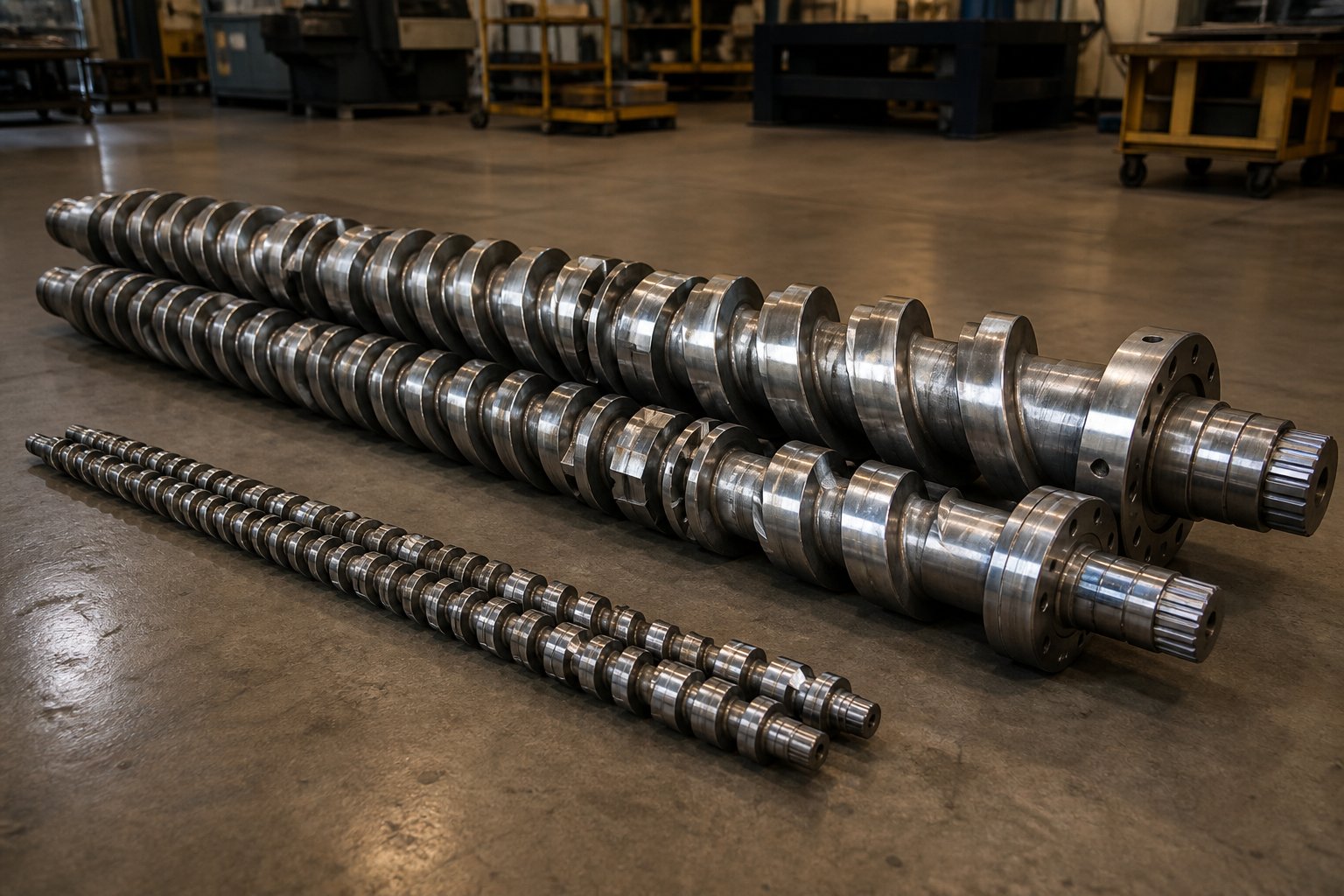
Scale-Up Methodology for Twin Screw Profiles
You spent weeks optimizing a screw profile on a 27 mm lab extruder. The compound hits every specification — dispersion is flawless, melt temperature stays within the thermal budget, volatiles are stripped below threshold, and pellet quality looks perfect. Then you transfer the profile to a 92 mm production machine, match the element sequence element-for-element, and the product falls apart. Dispersion drops, melt temperature spikes, and the vent port floods. What happened?
Scale-up happened. And the physics of scaling twin screw extrusion don't forgive assumptions. Transferring a lab to production twin screw screw design requires more than copying an element sequence — it demands understanding how geometry, energy, and heat transfer relationships shift as the bore diameter grows. This is arguably the most practically important and least documented aspect of twin screw extruder screw design, yet it's a challenge that process engineers face every time a successful lab trial needs to become a commercial process.
Geometric Similarity and Volumetric Scaling Principles
The foundation of any twin screw extruder scale-up methodology is the principle of geometric similarity. When you move from a small development extruder to a production-scale machine, the screw profile element sequence — the order of conveying elements, kneading blocks, mixing elements, and restrictive sections — should be preserved. Each element on the larger machine corresponds to its counterpart on the smaller one, with dimensions scaled proportionally to the bore diameter.
This geometric similarity principle for screw profile scaling sounds straightforward, but the volumetric implications are dramatic. Free volume inside the barrel scales with the cube of the diameter ratio. Double the bore diameter, and the available free volume increases by a factor of eight — not two, not four, but eight. Move from a 27 mm lab extruder to a 54 mm pilot machine (a 2x diameter ratio), and the volumetric capacity jumps roughly eightfold. Scale to a 92 mm production machine (approximately 3.4x the original diameter), and the free volume ratio exceeds 39x.
This cubic relationship is both the opportunity and the trap. It's the opportunity because it enables massive throughput increases — that's the whole point of scaling up. It's the trap because every other process-relevant parameter scales differently. Channel depths increase linearly with diameter, surface areas increase with the square of the diameter, and rotational tip speeds change based on the product of diameter and RPM. None of these follow the cubic volumetric relationship, which means the carefully balanced interactions between fill level, shear rate, heat transfer, and residence time on the lab machine will not automatically reproduce at larger scale.
The starting point for throughput estimation during scale-up is often the Schuler rule, which calculates the target feed rate on the larger machine based on the volumetric scale-up ratio. In practice, however, this theoretical throughput factor frequently requires adjustment. A scale-up trial from an 11 mm lab compounder running at 1 kg/h to a 16 mm machine predicted a throughput of 3 kg/h using the Schuler rule, but matching the original residence time and specific energy actually required reducing the feed rate to 2.5 kg/h — a meaningful deviation from the theoretical prediction that underscores why geometric scaling alone isn't sufficient.
Energy Scaling and Specific Energy Conservation
If geometric similarity preserves the screw profile's structural logic, specific energy conservation extrusion scale-up preserves its processing intent. The primary rule when transferring between machines is to maintain equivalent specific energy input (SEI, in kWh/kg) — because SEI captures the total mechanical energy delivered per unit mass, which is the closest single-number proxy for the combined effects of melting, mixing, and shear history that the material experiences.
The scale-up study published through AZoM illustrates this principle clearly. On the 11 mm extruder, the process ran at 200 rpm and 1 kg/h throughput, yielding a specific energy of 559 kJ/kg and a residence time of approximately 55 seconds. The first attempt at scale-up to the 16 mm machine — using the Schuler-rule throughput of 3 kg/h — produced significantly lower residence time and specific energy than the lab trial. Only when the feed rate was reduced to 2.5 kg/h did the residence time and specific energy (566 kJ/kg) align with the smaller machine's values. The lesson? Matching SEI often matters more than matching the theoretical volumetric throughput factor.
There's a deeper complication, though. Even when you successfully match total SEI between scales, the way that energy enters the melt changes. The main source of energy in twin screw compounding is the screw's shear energy — viscous dissipation generated as material is dragged through the clearances between flights, barrel walls, and kneading block lobes. On a larger machine, those clearances may not scale proportionally (manufacturing tolerances become relatively tighter), tip speeds change, and — critically — the surface-area-to-volume ratio decreases.
This last point deserves emphasis. Volume grows with the cube of diameter, but barrel surface area only grows with the square. That means a larger extruder has proportionally less barrel wall surface per unit volume of melt. Heat removal through barrel cooling becomes less efficient. Shear energy that was easily dissipated through the barrel wall on a 27 mm machine accumulates as melt temperature on a 92 mm machine. The same kneading block configuration that produced a perfectly controlled melt temperature in the lab can overheat the polymer at production scale — not because the blocks changed, but because the machine can no longer remove heat as effectively relative to the volume being processed.
The practical response? When scaling up, you may need to reduce the aggressiveness of kneading elements — replacing some 60-degree or 90-degree blocks with 45-degree or 30-degree alternatives — or substitute distributive mixing elements (TME, ZME) that deliver equivalent mixing quality with less viscous dissipation. The target SEI stays the same, but the profile must be modified so that energy enters the melt more gently, compensating for the reduced heat removal capacity of the larger barrel.
Practical Scale-Up Challenges and Adjustments
Beyond geometry and energy, a host of real-world complications surface when profiles move from lab to production. Each one can erode product quality if not anticipated and addressed in the screw configuration.
Residence time distribution broadens. Larger machines inherently produce wider RTDs because channel volumes are bigger, flow patterns become less uniform, and the relative influence of leakage flows and recirculation zones grows. For reactive extrusion, where tight RTD is essential for consistent conversion, this broadening can push some material into over-reaction while other portions under-react. The screw profile may need additional conveying length between mixing zones to restore plug-flow character and tighten the distribution.
Barrel heat transfer effectiveness drops. As the surface-to-volume ratio decreases, barrel temperature setpoints lose their influence on actual melt temperature. On a small lab machine, barrel heating or cooling can meaningfully shift the melt condition. On a large production extruder, the process becomes increasingly adiabatic — the melt temperature is dominated by viscous dissipation from the screw, not by barrel wall heat transfer. This shift means the screw profile itself becomes the primary thermal control tool at production scale.
Side feeder dynamics change. The volumetric capacity of side stuffers, the filler bulk density behavior in larger feed bores, and the interaction between filler introduction and local melt pressure all shift with scale. Vent port efficiency changes too — larger vent openings can handle more vapor flow, but the melt seal upstream must generate a more robust pressure dam to prevent melt intrusion into the enlarged vent cavity.
Anticipating these shifts means building specific screw profile adjustments into your scale-up plan. Common modifications include:
- Reducing kneading block aggressiveness: Swapping 90-degree neutral blocks for 60-degree forward blocks, or replacing long kneading sections with shorter blocks interspersed with conveying elements, to lower peak shear and localized temperature spikes.
- Adding conveying length between mixing zones: Extra conveying sections allow partial cooling through barrel contact and restore plug-flow character, tightening residence time distribution and reducing thermal accumulation.
- Adjusting melt seal positions relative to vent ports: Larger machines may require the restrictive element (reverse conveying or neutral kneading block) to be positioned slightly farther upstream from the vent opening to prevent melt from being pushed into the vent by the increased pressure differentials at higher throughput.
- Modifying discharge element geometry: The die pressure requirements at production throughput rates often differ from lab conditions. Tighter-pitch metering elements or additional conveying length in the discharge zone may be needed to achieve stable die flow without excessive energy input.
Scale-up is never a copy-paste exercise. The element sequence provides the starting skeleton, the specific energy target provides the thermodynamic anchor, and the practical adjustments listed above provide the fine-tuning that accounts for physics that simply don't scale linearly. Engineers who treat scale-up as a systematic methodology — rather than hoping the lab profile works unchanged on the big machine — consistently reach stable production faster and with fewer costly trial runs.
Scaling profiles successfully is one piece of a larger puzzle. Knowing when to select each element, how to map functional zones, and where simulation tools can replace physical trials — all within a repeatable, step-by-step framework — turns screw profile development from an art practiced by a few experienced engineers into a structured discipline that any process team can build on.
Building Your Screw Design Workflow from Concept to Production
Geometry, elements, trade-offs, material constraints, application strategies, scale-up physics — every section of this article has addressed a distinct piece of the screw profile puzzle. The missing piece? A repeatable process that connects them into a single decision chain. Without a structured workflow, even experienced engineers default to intuition and trial-and-error, burning extruder hours and raw material on iterations that a methodical approach would have eliminated before the first barrel section was bolted on.
Here's how to design a twin screw extruder screw profile from initial concept through validated production, step by step.
Step-by-Step Screw Profile Design Workflow
The following twin screw screw profile design workflow steps represent the sequence that consistently produces optimized configurations with the fewest iterations. Each step builds directly on the one before it — skip one, and the downstream decisions lose their foundation.
- Define processing objectives and output targets. What does the process need to accomplish? Compounding, reactive grafting, devolatilization, masterbatch production? What throughput rate, pellet quality, and product specifications must the final line deliver? These answers constrain every decision that follows. A vague objective produces a vague profile.
- Characterize material properties and formulation requirements. Document the base polymer's melt viscosity range, thermal degradation onset temperature, and moisture sensitivity. Identify filler types, loading levels, particle size distributions, and any reinforcements that impose shear limits (glass fibers, for instance). Map the thermal budget — the gap between required processing temperature and degradation threshold — because that budget caps your mixing intensity.
- Select the extruder platform and L/D ratio. Match the machine architecture (co-rotating vs. counter-rotating) to the mixing flexibility and pressure requirements identified in step one. Choose the shortest L/D ratio that accommodates every functional zone your process demands — feeding, melting, mixing, side feeding, venting, metering — with a modest margin for future formulation changes.
- Map functional zones along the barrel. Sketch each zone's position and approximate length in diameters. Assign feed ports, vent port locations, and side feeder positions. Verify that melt seal positions align with vent openings and that enough barrel length remains for downstream mixing and pressure building after the last vent.
- Select element types and configurations for each zone. This is where all the geometry knowledge pays off. Choose conveying element pitches for feed and vent zones, kneading block stagger angles and disc counts for melting and mixing zones, distributive mixing elements for shear-sensitive filler incorporation, and reverse elements or neutral blocks for melt seals. Apply the trade-off framework: balance mixing intensity against melt temperature rise, dispersive needs against distributive needs, and throughput targets against residence time requirements.
- Validate with simulation tools if available. Before committing to a physical trial, run the proposed profile through flow simulation software to predict fill level, pressure distribution, temperature evolution, and residence time distribution along the barrel. Industry-standard extrusion screw design simulation software tools — including Ludovic, WinTXS, and SIGMA — allow virtual prototyping of screw profiles, flagging problems like insufficient fill in mixing zones, excessive melt temperature at the die, or vent port flooding before a single element is mounted on a shaft.
- Trial and iterate on lab or pilot scale. Run the profile on a small-diameter extruder at geometrically scaled conditions. Measure specific energy input, melt temperature, die pressure, residence time distribution (using tracer methods if possible), and product quality metrics relevant to your specification. Adjust element selections based on results — swapping kneading block angles, adding or shortening conveying sections, repositioning melt seals — and re-run until the profile meets all targets.
- Scale up to production with appropriate adjustments. Preserve the element sequence while accounting for the scaling realities covered in the previous section: reduced surface-area-to-volume ratio, broadened residence time distribution, shifted side feeder and vent dynamics. Reduce kneading block aggressiveness if needed, add conveying length between mixing zones, and target the same specific energy input (kWh/kg) validated at pilot scale. Confirm product quality at the production throughput before locking the profile.
This eight-step sequence transforms screw profile optimization from concept to production into a traceable engineering process rather than a series of educated guesses.
Simulation and Computational Tools in Modern Screw Design
Step six deserves a closer look. The role of computational simulation in twin screw profile development has expanded significantly, and teams that leverage these tools gain a measurable advantage in development speed and first-trial success rates.
Platforms like Ludovic — originally developed at CEMEF in France and widely used across the polymer compounding industry — model the 1D flow, pressure, temperature, and fill level along the entire screw profile. You input the element sequence, barrel temperatures, screw speed, feed rate, and material rheology, and the software predicts how the melt behaves in each zone. SIGMA extends this concept with 3D simulation capabilities that can resolve local flow patterns around individual kneading block lobes and mixing elements — valuable when you need to understand shear distribution at a finer resolution than 1D tools provide. WinTXS offers similar process modeling capabilities with a focus on practical engineering workflows.
What do these tools actually save? Consider a typical compounding project where you're evaluating three candidate screw profiles with different kneading block arrangements. Without simulation, each profile requires a physical trial — mounting elements, running material, sampling product, cleaning, reconfiguring, and repeating. That cycle easily consumes two to three days of extruder time per profile, plus raw material costs and operator labor. With simulation, you can screen all three profiles computationally in hours, eliminate the weakest option before touching the machine, and enter the lab trial with a profile that's already been refined for fill level, temperature, and pressure behavior.
Simulation doesn't replace physical trials. Material rheology data is never perfect, wall slip effects are difficult to model precisely, and filler-polymer interactions introduce complexities that no current software captures completely. But simulation dramatically narrows the search space, turning step seven from a wide-open exploration into a focused validation of a computationally informed design.
Building Your Screw Design Capability
Tools accelerate the process. Fundamentals drive the decisions. Even the most sophisticated simulation software requires an operator who understands why a 60-degree kneading block behaves differently from a 45-degree block, why the OD/ID ratio constrains the shear envelope before any element is selected, and why the same profile that performs beautifully on a 27 mm lab extruder may overheat on a 92 mm production machine.
Building internal screw design capability starts with the knowledge base covered throughout this article — element geometry, architecture selection, trade-off navigation, material-driven design logic, and scale-up methodology. Teams that invest in understanding these fundamentals make better decisions faster, whether they're designing profiles in-house, interpreting simulation results, or collaborating with external partners.
Multiple paths lead to optimized profiles, and most successful organizations use a combination:
- Internal expertise development: Systematic trial programs, documented profile libraries tied to formulation families, and cross-training between process engineering and quality teams build institutional knowledge that compounds over time.
- Simulation adoption: Investing in computational tools like Ludovic, SIGMA, or WinTXS shortens development cycles and provides quantitative insight into profiles before committing to physical trials. The learning curve is real but pays dividends across every future project.
- Specialist collaboration: For organizations that need screw geometry specification, material selection guidance, and configuration recommendations tailored to specific polymers, machine platforms, and production requirements, working with experienced partners accelerates the path from concept to validated output. NANHAIYA's custom screw design services provide this type of support — delivering screw element recommendations, wear-resistant material-grade selections, and profile strategies matched to specific extruder classes and output targets. Whether the goal is developing a new compounding line or optimizing an existing profile that isn't meeting dispersion or throughput requirements, their cross-platform experience helps bridge the gap between processing objectives and hardware configuration.
These three paths aren't mutually exclusive — they reinforce each other. Internal expertise makes simulation results more interpretable. Simulation makes specialist recommendations more verifiable. And specialist input accelerates the internal learning curve by exposing your team to solutions they might not have encountered independently.
The goal of every screw profile design effort is the same: translate your processing objectives into a specific, validated element configuration that delivers consistent product quality at target throughput — and do it with the fewest possible iterations between concept and stable production.
That goal is achievable. The geometry fundamentals, element selection logic, process trade-offs, material-driven constraints, application strategies, scale-up methodology, and structured workflow presented across this article give you every conceptual tool you need. The rest is execution — systematic, data-driven, and iterative execution that turns screw profile design from an art practiced by intuition into an engineering discipline built on repeatable decisions.
Twin Screw Extruder Screw Design FAQs
1. What is the difference between co-rotating and counter-rotating twin screw extruder screw design?
Co-rotating twin screw extruders feature self-wiping intermeshing geometry that eliminates dead zones, supports an extensive library of modular elements (kneading blocks in multiple stagger angles, TME, ZME, SME), and delivers a wide mixing intensity range — making them ideal for compounding, reactive extrusion, and devolatilization. Counter-rotating designs create enclosed C-shaped chambers that act as positive-displacement pumps, excelling at gentle conveying with controlled pressure build-up. This makes them well-suited for thermally sensitive materials like PVC and calendering feed applications. The architecture you choose locks in your element library and mixing capability ceiling for the life of the machine.
2. How do kneading block stagger angles affect mixing in a twin screw extruder?
Kneading block stagger angles directly control the balance between conveying action, mixing type, and shear intensity. A 30-degree forward stagger maintains strong conveying with gentle distributive mixing and minimal temperature rise — suitable for heat-sensitive blending. At 45 degrees, conveying and mixing are balanced for general compounding. A 60-degree stagger shifts toward dispersive mixing with reduced forward flow, generating significant melt temperature increases useful for pigment dispersion. At 90 degrees (neutral), forward conveying effectively stops and maximum dispersive shear is achieved — critical for breaking hard agglomerates. Reverse kneading blocks pump material backward, creating melt seals essential upstream of vacuum vent ports in devolatilization profiles.
3. What L/D ratio should I choose for my twin screw extruder application?
The ideal L/D ratio depends on how many functional zones your process requires in a single pass. Short ratios (25:1-32:1) suit simple blending and masterbatch with minimal zone requirements. Medium ratios (36:1-44:1) handle standard compounding of engineering plastics, mineral-filled systems, and single-stage devolatilization with room for side feeding and one vent port. Longer ratios (48:1-52:1) are necessary for reactive extrusion needing controlled residence time, multi-stage devolatilization with two or three vacuum ports, or complex processes combining extensive mixing with downstream venting. Always select the shortest L/D that fits all required zones — unnecessary barrel length adds cost and can harm heat-sensitive formulations through extended thermal exposure.
4. How does OD/ID ratio affect twin screw extruder performance?
The outer-diameter-to-inner-diameter ratio is the most fundamental geometric parameter in twin screw design because it simultaneously controls free volume and shear intensity. A high OD/ID ratio (1.55-1.66) creates deeper screw channels with greater free volume and lower shear rates, suiting heat-sensitive polymers, fiber-reinforced compounds, and high-throughput blending. A low OD/ID ratio (1.22-1.40) produces shallow channels with high shear intensity, ideal for reactive extrusion, nanofiller dispersion, and high-shear compounding. Since the OD/ID ratio is fixed by the extruder platform, this decision is made at the machine selection stage and cannot be changed by rearranging screw elements.
5. How do you scale up a twin screw extruder screw profile from lab to production?
Successful scale-up follows three principles: preserve geometric similarity by maintaining the element sequence while scaling dimensions proportionally, conserve specific energy input (kWh/kg) as the primary process fingerprint, and compensate for physics that don't scale linearly. The critical challenge is that volume scales with the cube of the diameter ratio while barrel surface area only scales with the square — making heat removal less efficient on larger machines. Practical adjustments typically include reducing kneading block aggressiveness (e.g., replacing 90-degree blocks with 60-degree alternatives), adding conveying length between mixing zones for partial cooling, adjusting melt seal positions relative to vent ports, and modifying discharge elements for altered pressure requirements. For complex scale-up projects, working with specialists like NANHAIYA (nhyscrews.com/services/custom-screw-design) who have cross-platform experience can significantly reduce the number of costly production trials.
Written by
Nanhaiya Technical Team
Zhoushan Nanhaiya Plastic Machinery Co., Ltd.
The Nanhaiya technical team supports screw and barrel manufacturing projects through application review, technical communication, custom manufacturing coordination, and production and quality control.
Discuss Your Application
Related Articles
More insights on screw barrel technology and plastics processing.
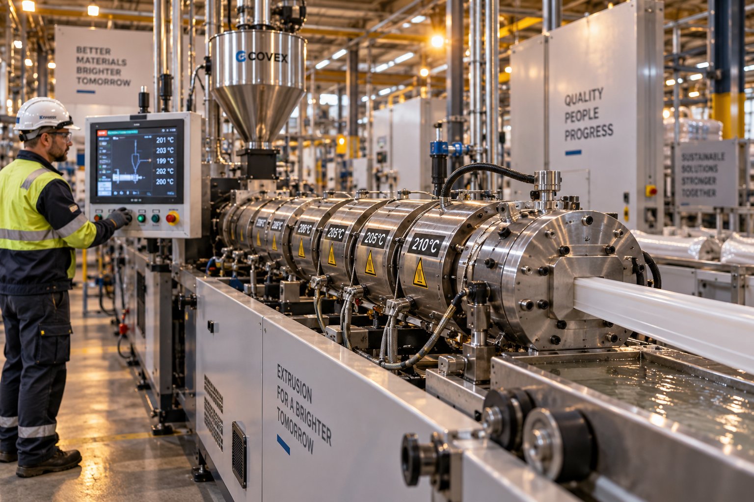
Plastic Extrusion Troubleshooting: Trace Every Defect to Its Source
Oct 16, 2026
Master plastic extrusion troubleshooting with this symptom-first guide. Diagnose defects zone by zone, fix root causes, and prevent recurring issues fast.
Read Article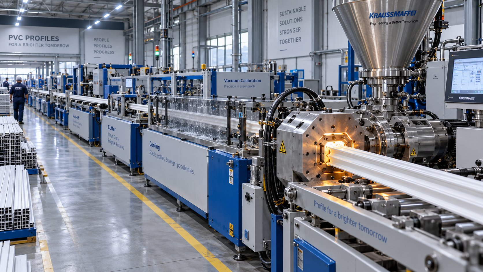
PVC Profile Extrusion Line Decoded: From Screw Design to Factory Floor
Oct 16, 2026
Learn how a PVC profile extrusion line works — from screw design and barrel profiling to troubleshooting, maintenance, and factory layout planning.
Read Article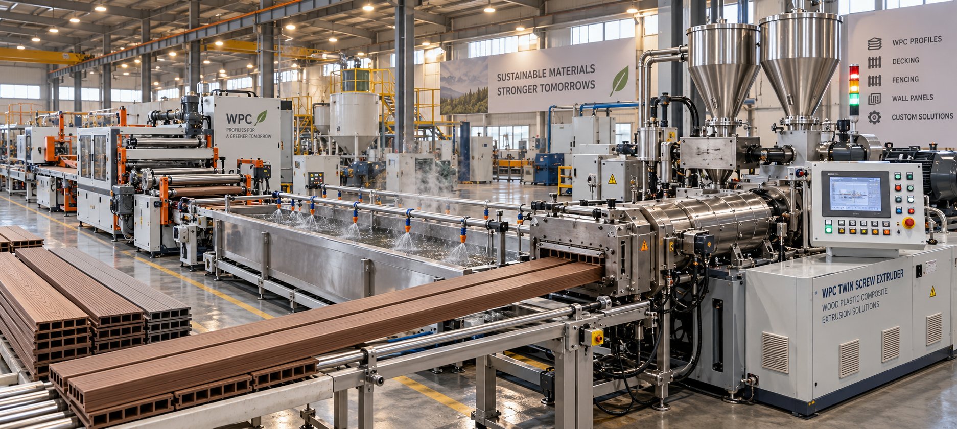
WPC Profile Extrusion Machine Decoded: Raw Blend To Flawless Profile
Oct 15, 2026
Learn how a WPC profile extrusion machine works — from extruder types and temperature zones to troubleshooting, wear management, and emerging co-extrusion trends.
Read ArticleLooking for something else?
Search by material, symptom or product and jump straight to the relevant page.
These are navigation suggestions based on keyword matching — not a quotation, not a delivery commitment, and not a substitute for engineering review. Final specification is confirmed by our engineers against your drawings and processed material.
Need help with screw barrel selection?
Share your machine model, processed material and application. Our team can help with pricing and technical support.