

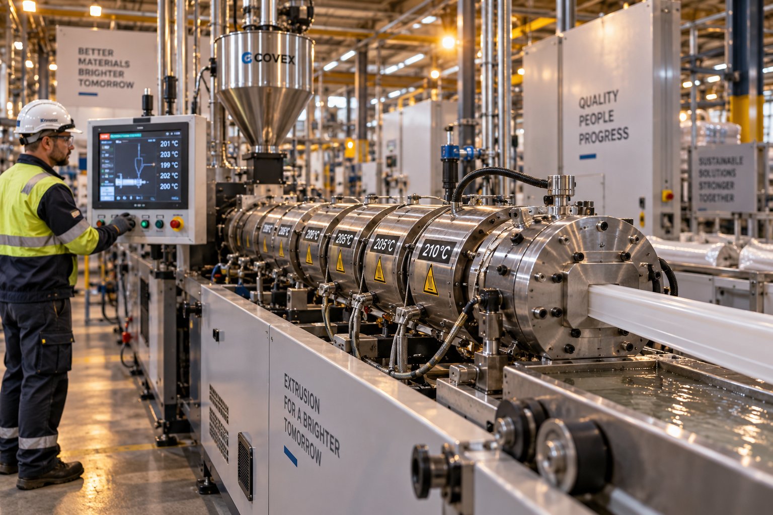
Understanding Plastic Extrusion Troubleshooting and Why It Matters
Plastic extrusion troubleshooting is the systematic process of identifying, diagnosing, and correcting defects and performance issues across the entire extrusion line — from hopper to puller. It goes far beyond swapping a setting when something looks wrong. True diagnostics means reading the symptoms your line is producing, tracing them back to their root causes, and applying targeted corrections that don't create new problems downstream.
This guide is built around a symptom-first diagnostic approach. You'll start from what you can see — surface roughness, dimensional shifts, bubbles, surging output — and work backward to the source. Along the way, you'll find a repeatable methodology, zone-by-zone temperature and pressure diagnostics, material-specific guidance, die and tooling analysis, regrind challenges, and preventive maintenance strategies designed to keep defects from appearing in the first place.
In extrusion, every defect is a message — the line is telling you exactly what went wrong if you know how to read the symptoms.
What Plastic Extrusion Troubleshooting Really Involves
There's a critical difference between a reactive fix and disciplined diagnostics. A reactive fix is turning the temperature up because the surface looks rough. Disciplined diagnostics means asking why the surface looks rough, checking melt pressure trends, verifying thermocouple accuracy, and confirming that the root cause isn't screw wear or moisture contamination before touching a single setpoint. Reactive fixes often mask one problem while silently introducing another. Unresolved defects compound into scrap, costly downtime, material waste, and even safety hazards that erode profitability shift after shift.
Why a Symptom-First Approach Works Best on the Production Floor
Operators don't encounter extrusion problems as textbook theory — they encounter them as a rough edge on a profile, an alarm for high melt pressure, or a bubble trail running through tubing. That's exactly why an extrusion troubleshooting symptom-first approach mirrors how problems actually surface. You notice the defect visually or through instrumentation, then you diagnose. Starting from theory and hoping to match it to a symptom is slower and less intuitive for floor-level decision-making.
How Extrusion Variables Are Interconnected
Here's what makes diagnosing extrusion defects genuinely challenging: temperature, pressure, screw speed, and melt viscosity form a tightly coupled system. Raise barrel temperature to fix a surface issue, and you may lower melt viscosity enough to alter die pressure and shift part dimensions. Increase screw speed to boost output, and — as simulation research confirms — both pressure and temperature climb in tandem due to added shear and friction. Isolated changes rarely produce isolated results. Understanding these interconnected extrusion variables is the difference between chasing symptoms in circles and solving problems on the first pass — and that starts with a structured methodology.
A Systematic Troubleshooting Methodology Every Operator Should Follow
Knowing that extrusion variables are interconnected is one thing. Having a disciplined process to untangle them on the production floor is something else entirely. Most wasted troubleshooting time doesn't come from a lack of knowledge — it comes from too many variables changing at once before the problem is even clearly defined. A repeatable extrusion troubleshooting methodology step by step eliminates guesswork and turns every correction into usable data.
The Five-Step Diagnostic Process for Extrusion Problems
Imagine two operators facing the same rough-surface defect. One immediately bumps die temperature by 10 degrees. The other pauses, documents the symptom, and checks melt pressure before touching anything. Twenty minutes later, the second operator has a fix that holds. The first has introduced a new dimensional problem. The difference? A structured process.
- Document the symptom precisely. What does the defect look like? When did it start? What changed recently — a new resin lot, a screen pack swap, a shift changeover? Capture this before memory fades or another adjustment muddies the picture.
- Establish a process baseline. Record current barrel zone temperatures, die temperatures, screw speed, melt pressure, melt temperature, and line speed. These numbers become your reference point for measuring whether any adjustment actually helped.
- Isolate the variable. Change only one parameter at a time, then allow the system to fully stabilize before evaluating the result. Extrusion has delayed responses — a temperature change may take several minutes to show up in the product.
- Work station by station. Break the line into diagnostic zones: feed section, transition/compression, metering, adapter, die, and downstream equipment. Check each zone systematically rather than jumping to the most convenient dial.
- Record results. Log every change, the time it was made, and the outcome. This builds institutional knowledge your entire team can reference during future issues.
Single variable isolation is the backbone of this process. When operators adjust screw speed, haul-off speed, and barrel temperature simultaneously, even a successful outcome teaches nothing — because no one knows which change actually worked.
Establishing a Process Baseline Before Making Adjustments
Skipping the baseline is the single most common reason operators chase problems in circles. Without documented starting values, you can't measure whether a correction moved the process in the right direction or made things worse. Think of it this way: if you don't know where you started, every reading you take afterward is just a number without context.
A practical baseline should capture these parameters at a minimum:
| Baseline Parameter | What to Record | Why It Matters |
|---|---|---|
| Barrel zone temperatures | Setpoint and actual for each zone | Reveals heater drift or thermocouple inaccuracy |
| Die temperatures | All zone setpoints and actuals | Identifies flow imbalances before they cause defects |
| Screw speed (RPM) | Current operating speed | Directly affects shear rate and output volume |
| Melt pressure | Adapter and/or die pressure readings | The most sensitive indicator of process stability |
| Melt temperature | Actual reading at the adapter | Confirms whether barrel setpoints are producing the intended result |
| Line speed / haul-off speed | Current speed setting and actual | Controls dimensions and draw ratio |
| Motor amps | Current draw at operating conditions | Flags feeding issues or screw wear over time |
Capturing this data takes minutes. Skipping it can cost hours of trial-and-error adjustments that lead nowhere.
Station-by-Station Diagnostic Thinking
A station by station extruder diagnostic process prevents the most damaging habit in troubleshooting: assuming the problem originates wherever it's most visible. A wall thickness variation you notice at the cutter might actually begin with unstable feeding at the hopper. Bubbles in a finished product might trace back to moisture that should have been caught before the feed throat.
Divide your line into these diagnostic zones and check each one in sequence:
- Feed section — Is material entering the screw consistently? Check for bridging, feed throat temperature, and material condition.
- Transition/compression zone — Is solid material melting progressively? Look for pressure instability or motor load fluctuations.
- Metering zone — Is the melt being delivered uniformly? Fluctuations here drive surging output.
- Adapter — Are there hot spots or flow hesitation? Check for degradation or pressure drops.
- Die — Is the extrudate shape and surface correct at the exit point? Inspect before blaming upstream zones.
- Downstream (sizing, cooling, puller, cutter) — Does the product change after leaving the die? If so, the extruder may not be the problem at all.
The practical rule is straightforward: walk the line from die exit backward. If the product looks correct leaving the die but distorts during cooling or pulling, your investigation belongs downstream. If it's already wrong at the die, work upstream through the barrel zones. This disciplined approach keeps your diagnostic energy focused on the right section of the line — and sets the stage for matching specific defects to their exact origins.
Common Extrusion Defects Diagnosed From Symptom to Root Cause
Walking the line station by station tells you where to look. The next question is: what exactly are you looking at? Every defect carries specific visual and dimensional signatures that point back to a finite set of root causes. Understanding the mechanics behind each one — not just memorizing a quick fix — is what separates an operator who solves problems permanently from one who patches them until the next shift.
Below is a symptom-first breakdown of the most common plastic extrusion defects and causes, organized so you can match what you see on the line to what's actually going wrong inside the barrel, die, or downstream equipment.
Surface Defects and Their Root Causes
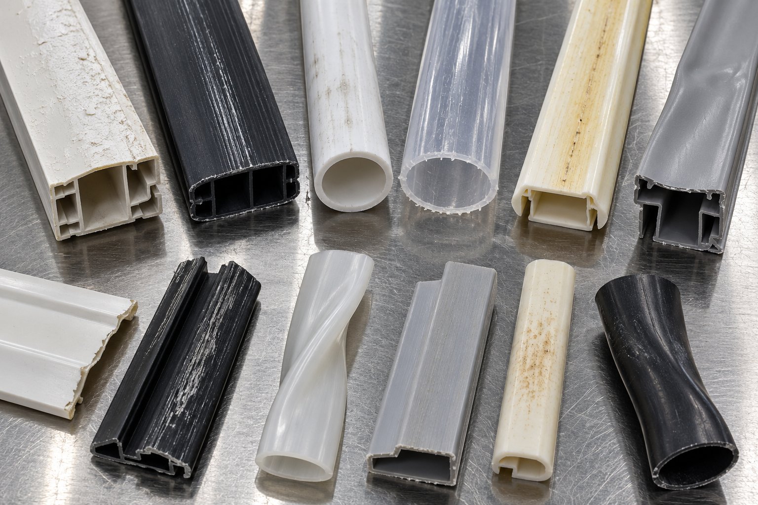
Melt fracture and shark skin. You'll notice these as wavy, rough, or ridged patterns on the extrudate surface. They look different — shark skin produces fine, regularly spaced ridges, while melt fracture creates more severe, chaotic distortions — but both originate from the same fundamental problem: excessive shear stress at the die lip. When the polymer is forced through the die land at a shear rate that exceeds its critical threshold, the melt literally tears as it exits. High-viscosity resins like HDPE are especially prone to this behavior at elevated output rates. So how do you fix melt fracture and shark skin in extrusion? Reducing the shear rate is the core strategy. That means lowering screw speed, raising melt temperature to decrease viscosity, widening the die gap, or shortening the die land length. Processing aids that promote wall slip at the die surface can also help in persistent cases.
Die lines. These appear as continuous, uniform streaks running in the extrusion direction. Unlike melt fracture, die lines are typically mechanical in origin — a nick, scratch, or polymer buildup on the die land surface creates a consistent mark that repeats across every inch of product. The fix is straightforward: inspect and clean the die lips, polish out any damage, and check for degraded material accumulating at the exit.
Rough or dull surface. When the extrudate surface lacks gloss or feels gritty, the melt temperature is often too low to produce a smooth, well-packed skin. Alternatively, the opposite can be true — thermal degradation from excessive heat breaks down the polymer chain, producing a surface that looks hazy or discolored. The diagnostic clue is direction: if raising melt temperature improves the finish, underheating was the cause. If the surface gets worse with more heat, degradation is already underway.
Discoloration and black specks. Yellowing, browning, or visible black specks in extruded plastic signal thermal degradation or contamination. Degradation occurs when polymer sits too long at elevated temperatures — in dead spots within the adapter, on worn screw flights, or in poorly flushed flow channels where material stagnates. Contamination from a different resin, additives, or environmental debris can also introduce specks. Tracking the timing helps: if specks appear immediately after startup, residual degraded material from the previous run is likely. If they develop gradually during production, look for hot spots or excessive residence time in the barrel.
Dimensional and Structural Defects Explained
Voids and bubbles. Bubbles trapped inside or on the surface of the extrudate almost always trace back to one of two root causes: moisture or air entrapment. For hygroscopic resins like PET and nylon, the mechanism is straightforward — absorbed water vaporizes under barrel heat and creates gas pockets within the melt. For non-hygroscopic materials, the voids and bubbles in extrusion root cause is more likely air drawn into the feed section due to starve feeding, poor pellet geometry, or excessive fines. Decompression in the metering zone or a poorly vented screw design can also trap volatiles.
Dimensional instability. When wall thickness, profile dimensions, or tube diameter drift over time, the melt delivery rate is inconsistent. This is a direct reflection of melt pressure variation — if pressure at the die fluctuates, the volumetric output changes, and dimensions follow. Inconsistent puller or haul-off speed compounds the problem. The corrective approach targets both: stabilize melt pressure through barrel and screw optimization, then verify downstream equipment is maintaining constant draw.
Warping. Products that twist, bow, or curve after leaving the die are experiencing uneven cooling. One side solidifies faster than the other, locking in differential shrinkage stresses. Semi-crystalline polymers like PP are especially susceptible because their crystallization behavior amplifies shrinkage differences. The fix focuses on cooling uniformity — balanced water flow in calibration tanks, even air distribution in cooling rings, and proper support to prevent gravity-induced distortion during the critical solidification window.
Output Surging and Inconsistent Throughput
Surging is the rhythmic rise and fall of extruder output that shows up as periodic thickness variations, pressure oscillations, or visible pulsing at the die exit. Of all common defects, surging is the one most directly tied to screw and barrel condition.
The most frequent cause? Poor solids conveying in the feed section. Research from Dow's extrusion team demonstrates that improper temperature on the screw surface or feed casing is the primary driver — when the feed zone runs too hot, pellets soften prematurely and lose the frictional grip needed for consistent forward transport. A hot feed casing or inadequate screw cooling creates the same cyclic pattern: output drops as conveying falters, pressure falls, the controller compensates by increasing screw speed, and the cycle repeats.
Other extrusion surging causes and corrective actions include:
- Screw wear — Increased clearance between the screw flight and barrel wall reduces pumping efficiency in the metering zone, creating output instability that worsens over time.
- Bridging — Material clumps in the hopper or feed throat, interrupting the flow of pellets to the screw. Check for moisture-induced clumping, oversized regrind, or a feed throat temperature that's too high.
- Inconsistent feeding — Variations in bulk density, pellet size, or blending ratios cause uneven screw fill, producing output fluctuations that mirror feeding irregularities.
When troubleshooting surging, the practical first step is simple: feel the feed casing. It should be warm, not hot. Then verify screw cooling flow if your extruder uses it. These two checks alone resolve the majority of surging cases in smooth-bore extruders.
Quick-Reference Diagnostic Chart
The table below consolidates everything above into a printable reference you can use directly on the production floor. Match the symptom to its most likely root causes, then check the diagnostic zone indicated to narrow your investigation.
| Defect Symptom | Primary Root Causes | Key Corrective Actions | Diagnostic Zone |
|---|---|---|---|
| Melt fracture / shark skin (wavy, ridged surface) | Excessive shear stress at die lip; high output rate with high-viscosity resin | Reduce screw speed; raise melt temperature; widen die gap; add processing aid | Die |
| Die lines (continuous streaks along extrusion direction) | Damaged, scratched, or contaminated die land | Inspect and polish die lips; clean buildup from land surfaces | Die |
| Rough or dull surface | Melt temperature too low or too high (degradation) | Adjust barrel/die temperatures incrementally; check for degradation signs | Barrel / Die |
| Discoloration / black specks | Thermal degradation in dead spots; contamination; excessive residence time | Purge system; eliminate dead spots in adapter; verify material purity | Barrel / Adapter |
| Voids / bubbles | Moisture in resin; air entrapment at feed; inadequate venting | Pre-dry hygroscopic resin; check feed throat and screw venting; reduce fines | Feed / Barrel |
| Dimensional instability (wall thickness drift) | Melt pressure fluctuation; inconsistent puller speed | Stabilize barrel/metering temperatures; calibrate puller speed; check screw wear | Metering / Downstream |
| Warping (twist, bow, curve) | Uneven cooling; differential shrinkage; high crystallinity resin | Balance cooling water flow; adjust cooling ring/air knife; support product during solidification | Downstream |
| Surging (cyclic output variation) | Feed zone overheating; screw wear; bridging; inconsistent material feeding | Check feed casing temperature; verify screw cooling; inspect screw/barrel clearance; ensure consistent feed | Feed / Metering |
Each defect in this chart points to a specific zone along the extrusion line — but notice that several root causes overlap between zones. Temperature problems, for instance, can manifest as surface defects at the die even when the actual issue originates three zones upstream. That overlap is exactly why the next step in effective diagnostics is a detailed, zone-by-zone walkthrough of temperature and pressure behavior across the entire barrel length.
Zone-by-Zone Temperature and Pressure Diagnostics Along the Barrel
A defect chart tells you which zone to investigate. But once you're standing in front of a barrel with six or more independently controlled heating zones, you need a sharper question: what does "wrong" actually look like in this specific zone? Extruder barrel zone temperature troubleshooting requires understanding what each section of the barrel is supposed to accomplish — and recognizing the distinct symptoms that appear when it fails.
A typical single-screw extruder has four to eight heating and cooling zones, each set to a specific temperature that creates a progressive melt profile from hopper to die. Together, these zones form the thermal fingerprint of your process. When that fingerprint shifts — even subtly — the product changes.
Feed Zone and Transition Zone Temperature Diagnostics
The feed zone is where solid pellets enter the screw channel and begin moving forward. Its job isn't to melt the polymer — it's to convey it. That distinction matters enormously for diagnostics.
Feed zone overheating bridging problems are among the most misdiagnosed issues on the production floor. When this zone runs too hot, pellets begin softening prematurely against the barrel wall and screw surface. Softened pellets lose the frictional grip they need to be pushed forward by the screw flights. The result? Material clumps together, bridges across the feed throat, and forward conveying slows or stops entirely. Output drops, melt pressure falls, and surging begins — all because the very first zone was a few degrees too warm. As a practical check, the feed casing should feel warm to the touch, never hot. If your extruder uses water cooling on the feed section, verify that the flow rate and water temperature are within spec before adjusting anything else.
Underheating the feed zone creates the opposite problem. Pellets remain too rigid, resist compaction into the screw channel, and feed inconsistently. You'll see erratic motor amp readings and intermittent pressure dips at the adapter.
The transition (or compression) zone sits directly downstream. Here, the screw channel depth decreases progressively, mechanically compressing the material while barrel heat begins melting it. Temperature in this zone must increase gradually to match the decreasing channel depth. If the temperature profile jumps too aggressively, the polymer melts unevenly — some pellets fully molten while others remain solid. This mismatch disrupts the solid bed and creates pressure instability that propagates all the way to the die. If the transition zone runs too cool, unmelted solids pass into the metering section, increasing motor load and producing visible unmelt defects in the finished product.
Metering Zone and Adapter Temperature Control
The metering zone is the heart of melt uniformity. Its screw channel depth is constant, and its primary function is to deliver a fully homogenized melt at a consistent volumetric rate. Any metering zone temperature fluctuation surging relationship becomes immediately obvious here: even small thermal variations change melt viscosity, which changes the pumping rate, which creates the rhythmic output oscillation operators recognize as surging.
Consistency in this zone matters more than hitting a specific number. A metering zone that holds steady at 415 degrees Fahrenheit will produce better product than one that swings between 410 and 420, even though the average is the same. When you see surging on an otherwise well-fed extruder, check the metering zone heater performance and thermocouple accuracy before blaming the screw.
The adapter — the section connecting the barrel to the die — is a diagnostic blind spot on many lines. Temperature drops in the adapter cause the melt to hesitate, increasing residence time in that section and promoting thermal degradation. Hot spots do the opposite: they reduce local viscosity, creating flow imbalances that show up as dimensional inconsistency in the final product. Discoloration or black specks that appear only intermittently often trace back to an adapter zone where degraded polymer periodically breaks free from a stagnant pocket.
Die Zone Balancing and Melt Pressure Monitoring
Each die zone controls a specific portion of the extrudate profile, sheet width, or film circumference. Temperature imbalances between die zones cause material to flow faster through the hotter sections and slower through the cooler ones, producing measurable thickness variation. For profile extrusion, this means one wall thicker than the other. For film, it means gauge bands that repeat at consistent positions across the web.
Die zone adjustments should always be made in small increments — typically five to ten degrees at a time — because the die's thermal mass means changes take longer to stabilize than barrel zone adjustments. Patience here prevents overcorrection.
Of all the data available on the extrusion line, melt pressure monitoring extrusion diagnostics stands out as the single most valuable signal. Melt pressure — measured at the adapter or die inlet — integrates the combined effects of screw performance, material viscosity, screen pack condition, and die restriction into one number. A stable melt pressure reading, typically holding within plus or minus 50 PSI during steady-state operation, means the entire upstream process is delivering consistent output. When pressure begins to oscillate, drift upward, or trend downward, something has changed — and the pattern of that change tells you what.
- Gradual pressure rise points to screen pack loading or die land buildup restricting flow.
- Gradual pressure decline at constant screw RPM suggests screw wear reducing pumping efficiency — worn flights allow increasing polymer backflow, lowering the effective output rate.
- Rhythmic pressure oscillation (cycling at regular intervals) signals surging from inconsistent melting or feeding.
- Sudden pressure spikes or drops indicate acute events — a clogged screen, a feed interruption, or a heater band failure.
Steady melt pressure means steady output. If you can only watch one instrument on the extrusion line, make it the pressure transducer at the adapter.
Hidden Diagnostic Traps: Heater Bands, Thermocouples, and Contact Issues
Even when operators follow a disciplined zone-by-zone approach, three hidden traps can make perfectly logical diagnoses fail.
Heater band failure. A partially failed heater band doesn't always trigger an alarm. Instead, it creates a subtle cold zone that adjacent heaters try to compensate for — driving their duty cycles higher and distorting the temperature profile without an obvious alert. You'll notice the neighboring zones running hotter than their setpoints, or heater duty cycles creeping from a normal 40-70% range toward 85-90% and beyond. Tracking individual zone duty cycles over time is one of the earliest indicators that a heater band is approaching failure.
Thermocouple drift. A degraded thermocouple sends inaccurate readings to the temperature controller, which then adjusts heater output based on a phantom signal. The displayed temperature looks normal, but the actual barrel wall temperature is wrong. The result is a zone that overheats or underheats while the screen says everything is fine. Misaligned or poorly seated thermocouples can trick the PID controller into driving a heater band continuously — burning it out prematurely and creating a cascading failure. If a zone's behavior doesn't match its readings, swap the thermocouple before adjusting anything else.
Poor barrel-to-heater contact. Band heaters must fit snugly against the barrel's outer diameter. If a heater band is loose, installed over residual polymer residue, or missing thermal transfer compound, it can't efficiently transfer heat into the barrel steel. The heater overworks, the zone underperforms, and the operator sees a temperature that never quite reaches setpoint — or one that overshoots wildly as the controller overcompensates.
The table below consolidates zone-by-zone diagnostic indicators into a quick-reference format. Use it alongside your melt pressure data to isolate where a thermal problem originates.
| Zone | Typical Function | Symptoms of Overheating | Symptoms of Underheating | Key Diagnostic Check |
|---|---|---|---|---|
| Feed zone | Convey solid pellets into the screw channel | Pellet bridging; reduced output; surging; feed throat feels hot | Erratic feeding; inconsistent motor amps; poor screw fill | Feel the feed casing; verify cooling water flow and temperature |
| Transition / compression zone | Gradually melt and compress the polymer | Premature full melting; pressure instability; degradation risk | Unmelt in product; increased motor load; uneven melt | Compare zone temperature profile to recommended gradient for the resin |
| Metering zone | Deliver fully homogenized melt at a consistent rate | Reduced melt viscosity; dimensional instability; possible degradation | Incomplete homogenization; higher melt pressure; surging | Monitor melt pressure stability; check heater duty cycle consistency |
| Adapter | Transfer melt from barrel to die with minimal flow disruption | Localized degradation; discoloration; black specks | Flow hesitation; increased residence time; pressure drop | Inspect for dead spots; verify thermocouple accuracy and heater contact |
| Die zones | Shape the melt into the final profile, sheet, or film | Faster flow in overheated sections; thickness variation; possible degradation | Slower flow in cool sections; uneven wall thickness; surface roughness | Measure product dimensions at multiple points; adjust zones in 5-10 degree increments |
Temperature and pressure diagnostics give you the ability to pinpoint where a problem lives along the barrel. But the same zone settings that work flawlessly for one polymer can produce catastrophic results with another. Different resins have fundamentally different melting behaviors, thermal sensitivities, and degradation thresholds — which means effective troubleshooting requires knowing not just your equipment, but your material.

Material-Specific Troubleshooting for Common Polymers and Film Lines
A perfectly tuned temperature profile for polyethylene can destroy a PVC compound in minutes. A drying protocol that's optional for polypropylene is an absolute survival requirement for PET. This is the reality that makes material-specific extrusion processing problems so treacherous — and why generic troubleshooting advice only gets you halfway to a solution.
Each polymer family brings its own melting behavior, shear sensitivity, thermal degradation threshold, and moisture tolerance to the extruder. A corrective action that rescues one resin can ruin another. The guidance below breaks down the five most commonly extruded polymers so you can adjust your diagnostic thinking based on what's actually running through the barrel.
| Polymer | Typical Processing Range | Common Defects | Moisture Sensitivity | Degradation Behavior | Special Considerations |
|---|---|---|---|---|---|
| PE (HDPE / LDPE) | 350-530 °F (175-275 °C) | Melt fracture; shark skin; oxidative discoloration | Low — generally non-hygroscopic | Oxidative degradation at elevated temperatures; crosslinking or chain scission depending on PE type | HDPE prone to melt fracture at high output; LDPE more forgiving but sensitive to overheating |
| PP | 400-500 °F (205-260 °C) | Warping; sink marks; brittleness at weld lines | Low — non-hygroscopic | Oxidative chain scission; rapid viscosity drop at degradation onset | High crystallinity drives shrinkage and warping; narrower processing window than PE |
| PVC | 320-410 °F (160-210 °C) | Burn marks; discoloration; plate-out on die | Low | Releases hydrochloric acid (HCl) gas when overheated; autocatalytic degradation accelerates rapidly | Requires low-shear screw design; thermal history is cumulative; stabilizer package is critical |
| PS | 350-480 °F (175-250 °C) | Brittleness; stress cracking; dull or rough surface | Low to moderate | Chain scission producing styrene monomer; yellowing at excessive temperatures | Sensitive to stress cracking from residual orientation; surface quality demands adequate melt temperature |
| PET | 480-550 °F (250-290 °C) | Splay; bubbles; haze; IV loss; dimensional instability | Very high — highly hygroscopic | Hydrolytic degradation from moisture; thermo-oxidative degradation above 280 °C; chain-end scission accelerates with lower molecular weight | Must be dried to below 0.02% moisture before processing; feed zone cooled to ~50 °C; vented extruders preferred |
Troubleshooting PE and PP Extrusion Problems
Polyolefins — PE and PP — are the workhorses of extrusion. They're relatively forgiving compared to engineering resins, but each carries distinct traps that catch operators off guard.
HDPE and LDPE. The most common headache with HDPE extrusion is melt fracture at high throughput rates. HDPE's relatively high melt viscosity means the shear stress at the die lip climbs quickly as you push output. You'll see it first as fine shark skin ridges, progressing to gross melt fracture if output continues to increase. HDPE LDPE extrusion melt fracture solutions center on reducing the shear rate at the die exit: lower screw speed, increase melt temperature slightly to reduce viscosity, widen the die gap, or introduce a fluoropolymer processing aid that promotes slip at the die wall. LDPE is more forgiving on shear because of its long-chain branching, which provides natural shear-thinning behavior — but LDPE is more sensitive to oxidative degradation. Extended residence time at elevated temperatures causes crosslinking in LDPE, producing gels that show up as small hard spots in film or sheet. Keeping residence time short and minimizing air exposure in the hopper reduces this risk.
PP. Polypropylene's challenge is crystallinity. PP crystallizes rapidly and substantially during cooling, producing higher shrinkage rates than PE. That shrinkage isn't always uniform — it depends on cooling rate, wall thickness, and flow orientation — which is why PP parts are especially prone to warping, curling, and sink marks. When you see a PP profile bowing after the cooling tank, the instinct is to blame the die. More often, the root cause is uneven cooling: one side of the profile solidifying faster locks in differential shrinkage stress that distorts the part after it exits the calibrator. PP also has a narrower processing window than PE. Its viscosity drops sharply once degradation begins, and unlike PE's crosslinking tendency, PP degrades by chain scission — the molecular chains break apart, viscosity plummets, and the melt becomes too thin to hold shape. If your PP extrudate suddenly starts sagging or losing dimensional stability, check for thermal degradation before adjusting downstream equipment.
PVC Processing Challenges and Thermal Sensitivity
PVC stands apart from every other common extrusion polymer because of one critical property: its degradation temperature sits dangerously close to its processing temperature. The window between "fully melted" and "actively decomposing" can be as narrow as 10-20 degrees, making PVC extrusion troubleshooting thermal degradation one of the highest-stakes diagnostic challenges on the production floor.
When PVC overheats, it doesn't just discolor — it releases hydrochloric acid gas, which is both corrosive to equipment and hazardous to operators. Worse, this degradation is autocatalytic: the HCl released accelerates further decomposition, creating a runaway reaction that can char an entire barrel in minutes if not caught early. The first warning sign is usually a subtle color shift — the extrudate moves from its expected shade toward amber or brown. If you see this, reduce temperatures immediately and purge the system. Waiting to "see if it stabilizes" only deepens the degradation.
PVC also demands a fundamentally different screw design than polyolefins. Standard high-compression screws generate too much shear heat in PVC compounds, pushing the material past its thermal limit even when barrel setpoints look safe. PVC screws use lower compression ratios, often in the range of 1.5:1 to 2.0:1, compared to the 2.5:1 to 3.5:1 ratios common for PE and PP. The goal is to melt the PVC primarily through conductive heat transfer from the barrel rather than through frictional shear from the screw.
Because PVC's thermal history is cumulative — every second at elevated temperature contributes to degradation — minimizing residence time is critical. Dead spots in the adapter, oversized barrels running at low output rates, and long startup or shutdown sequences all increase the risk. Operators who process PVC should also closely monitor the stabilizer package in their compound, since the stabilizer is the only thing preventing degradation during normal processing. If a compound runs fine for weeks and then suddenly begins discoloring, a change in stabilizer concentration or quality is often the culprit.
Hygroscopic Resins — PET, Nylon, and ABS Drying Requirements
Imagine spending thirty minutes fine-tuning barrel temperatures and die gaps to eliminate bubbles — only to discover the resin was wet. For hygroscopic polymers, moisture isn't a secondary variable. It's the primary one.
PET is the most demanding of the common extrusion resins when it comes to PET extrusion drying requirements moisture defects. PET must be processed with a moisture content below 0.02% by weight. Research on PET extrusion shows that drying at 120-150 °C for approximately four hours achieves the target moisture level — but here's the catch: dried PET exposed to ambient air at 50% relative humidity can reabsorb enough moisture to exceed the 0.02% threshold in as little as 15 minutes. That means PET must be processed immediately after drying, and the feed system must be sealed against ambient humidity.
When PET processes with excess moisture, hydrolysis occurs almost instantly in the melt phase. Water molecules attack the polymer chain, breaking it apart and causing a dramatic viscosity drop. The practical consequences are severe: splay marks on the extrudate surface, internal bubbles, haze in sheet and film, and a measurable loss of intrinsic viscosity (IV) that permanently weakens the material. Undried PET can lose more than 50% of its viscosity in an oxygen-rich environment, with virtually instantaneous hydrolysis creating a melt that's too thin to control.
PET also requires specific screw configurations. Barrier screws with grooved feed barrels improve solids conveying significantly, and the feed section should be cooled to approximately 50 °C — high enough to prevent condensation but low enough to maintain the friction needed for conveying. Processing temperatures typically fall within a narrow 250-270 °C window; above this range, thermo-oxidative degradation produces formaldehyde and acetaldehyde byproducts that compromise product quality and safety.
Nylon (PA) shares PET's hygroscopic sensitivity, though its processing window is somewhat more forgiving. Nylon should be dried to below 0.1-0.2% moisture content, typically at 80-85 °C for four to six hours depending on the grade. Wet nylon produces the same bubble and splay defects as wet PET, along with reduced mechanical properties in the finished product.
ABS is moderately hygroscopic and typically requires drying at 80-85 °C for two to four hours to reach target moisture levels. Moisture-related defects in ABS appear as surface splay, silver streaks, and reduced impact strength. Unlike PET, ABS is somewhat more tolerant of minor moisture variations — but processing undried ABS will still produce visible surface defects that cannot be corrected by temperature adjustments alone.
The universal rule for all hygroscopic resins: if you see bubbles, splay, or unexplained surface defects, check the dryer performance before touching barrel temperatures. Verify desiccant condition, dewpoint readings, hopper residence time, and material throughput rate. A dryer that's technically running but delivering insufficient dewpoint temperatures is functionally the same as no dryer at all.
Blown Film and Thin Film Specific Defects
Film extrusion introduces an entirely separate category of defects that don't exist in profile or pipe lines. Blown film bubble instability troubleshooting is a specialized discipline because the bubble itself is a dynamic, three-dimensional structure influenced by melt viscosity, air pressure, cooling rate, and haul-off speed simultaneously.
Bubble instability. When a blown film bubble sways, breathes (expands and contracts rhythmically), or collapses, the root cause is almost always an imbalance between the internal air pressure holding the bubble open and the melt strength resisting that pressure. Low melt strength — caused by excessive melt temperature, degraded resin, or a resin grade with insufficient molecular weight — makes the bubble unable to hold its shape. External factors compound the problem: drafts in the plant, uneven cooling air distribution from the air ring, or a die with unbalanced flow channels that delivers more material to one side than the other.
Gauge variation. Thickness inconsistency around the circumference of a blown film bubble points to die flow imbalances or uneven cooling. If the gauge variation is fixed in position (the thick spot always appears in the same place relative to the die), the die lip gap or flow channel is uneven. If the variation rotates, an oscillating air ring or thermal draft is the likely cause. Many film lines use rotating dies or oscillating haul-offs to average out minor gauge variation across the finished roll — but these are compensation strategies, not fixes for the underlying problem.
Blocking. Film layers that stick together on the roll are experiencing blocking — typically caused by insufficient cooling before winding, excessive slip additive migration to the surface, or a melt temperature that's too high for the resin's anti-block additive package to handle. Reducing melt temperature, increasing the frost line height to allow more cooling time, or adjusting anti-block and slip additive levels in the compound are the standard corrective actions.
Whether you're running polyolefin blown film, PVC sheet, or PET strapping, the key insight is the same: the polymer dictates the rules. Generic "raise the temperature" or "slow down the screw" advice fails precisely because it ignores the material's unique thermal and rheological fingerprint. Die and tooling problems share this same material-dependent behavior — which is why the die itself deserves its own focused diagnostic examination.
Die Tooling Problems and Recycled Material Challenges Most Operators Miss
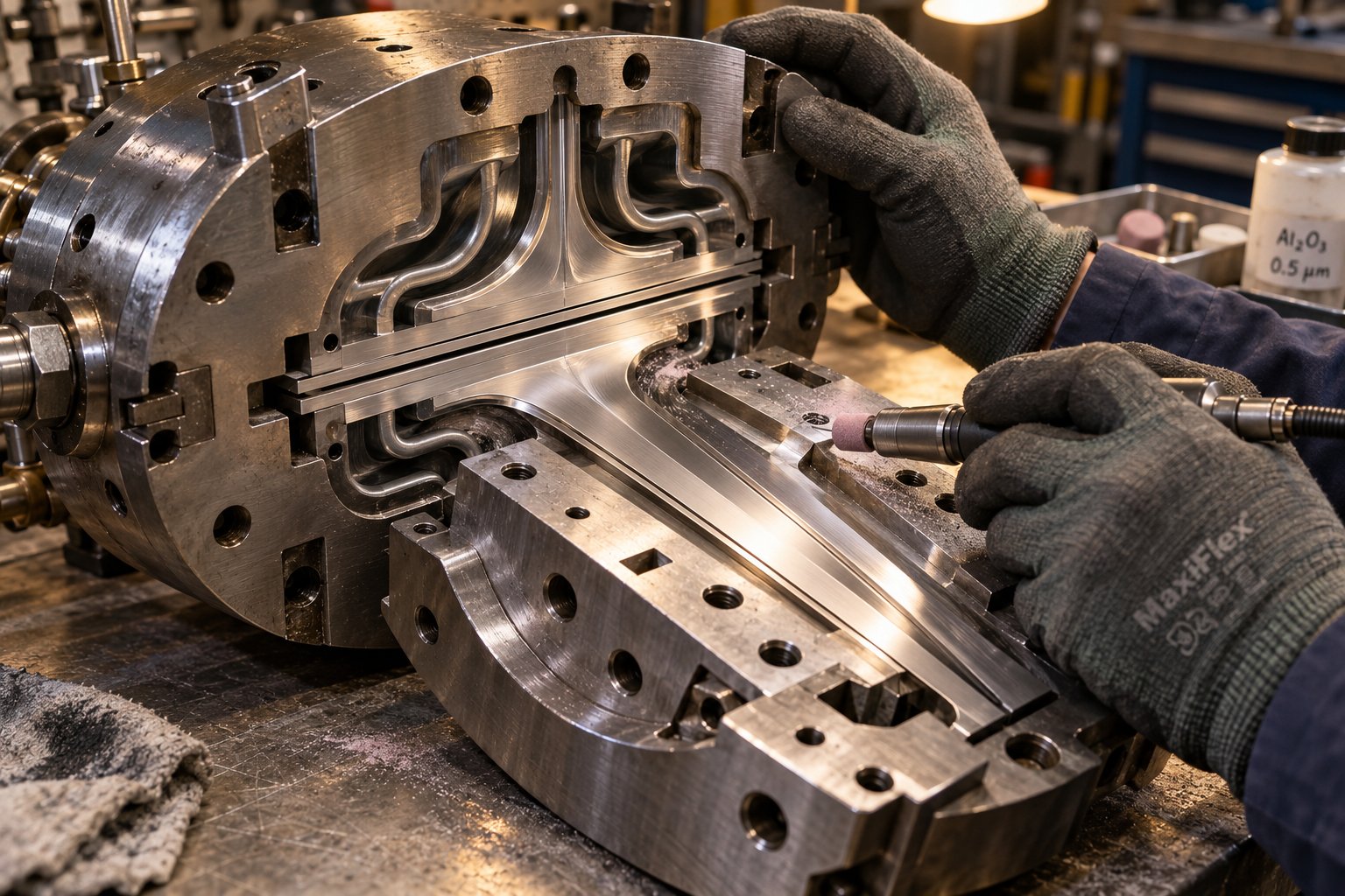
The previous section made a critical point: the polymer dictates the rules. But even when the resin is perfectly dried, the barrel profile is dialed in, and the screw is delivering stable melt pressure, defects can still appear — because the die itself is the problem. This is one of the most common diagnostic blind spots in plastic extrusion troubleshooting. Operators instinctively adjust barrel temperatures or screw speed when they see surface streaks or thickness variation, but the actual root cause is sitting at the very end of the line, right at the die exit.
How do you know the die is to blame? Look for these telltale symptoms that point specifically to die-related causes rather than barrel or screw issues:
- Surface streaks or lines that remain in the same position relative to the die, even when screw speed or barrel temperatures change
- Thickness variation that maps consistently to specific die zones rather than fluctuating randomly over time
- Defects that worsen progressively during a production run but improve immediately after die cleaning
- Extrudate dimensions that exceed die opening dimensions by a consistent, predictable ratio (die swell)
- Product quality that degrades only at high output rates while remaining acceptable at lower speeds
If any of these patterns match what you're seeing, resist the urge to tweak barrel zones. Start your investigation at the die.
Die Lip Buildup, Flow Imbalance, and Land Length Issues
Die lip buildup. Over time, degraded polymer accumulates on the die lip surfaces — the very last surface the melt contacts before exiting. This buildup creates drag marks, streaks, and rough patches that worsen as the run continues. The causes are straightforward: material that contacts the hot die surface for extended periods begins to degrade, and the degraded residue sticks. High-viscosity polymers and thermally sensitive materials like PVC are especially prone to this. Industry data suggests that nearly 30% of production interruptions in extrusion can be attributed to die buildup, and companies maintaining strict cleaning protocols reduce buildup events by close to 40%.
Effective management of extrusion die lip buildup causes and cleaning requires a two-pronged approach. First, establish a regular cleaning schedule based on the material being processed — thermally sensitive resins need more frequent attention. Cleaning methods range from mechanical scrapers and brass brushes for routine maintenance to solvent cleaning or even burn-off ovens for heavily fouled dies. Second, address the conditions that accelerate buildup: sharp corners or sudden cross-sectional changes in the die's flow channel trap material and create stagnation zones where degradation begins. Non-stick coatings like PTFE applied to the die lip surfaces can also reduce adhesion and extend the interval between cleanings.
Flow channel imbalances. When the melt doesn't distribute evenly across the die's internal channels, the extrudate comes out thicker on one side and thinner on the other. This extrusion flow channel imbalance thickness variation is especially problematic in flat dies for sheet and film, where even small flow asymmetries create gauge bands that repeat at consistent positions across the web width. For profile dies, imbalanced flow means one wall section fills faster than another, distorting the cross-section.
The corrective tools depend on your die design. Flat sheet and film dies use choker bars or flex-lip adjustment bolts across the die width — tightening a bolt locally restricts flow, diverting more material to the thinner areas. Profile dies may require internal flow restrictor pins or land-length modifications to balance the flow. The critical diagnostic step is mapping where the thick and thin spots are, confirming they're fixed relative to the die position (not rotating or shifting), and then adjusting the corresponding die zone. If the variation moves around randomly, the problem isn't the die — it's upstream pressure instability.
Die gap settings. The gap between the die lips directly controls back pressure and the degree of melt stretching at the exit. Set the gap too narrow, and you increase shear stress dramatically — pushing the melt toward melt fracture, raising head pressure, and increasing the risk of degradation from frictional heating. Set it too wide, and the melt exits with insufficient stretching and orientation, producing an extrudate with lower mechanical properties and poor dimensional control. Finding the right die gap is always a balance between output rate, melt viscosity, and the target product dimensions.
Land length. The die land is the parallel section at the very end of the flow channel — the last straight run before the melt exits. Short lands reduce pressure drop and residence time but produce extrudates that are less dimensionally stable because the melt has insufficient time to develop a uniform velocity profile across the channel. Long lands improve extrudate stability and surface finish but increase both pressure drop and the time material spends at elevated temperature, raising the risk of thermal degradation. Optimizing land length is a design decision made when specifying the die, but understanding its effect helps operators diagnose why one die produces better results than another on the same extruder.
Die swell. Ever notice that the extrudate is slightly larger than the die opening? That's die swell — and it's not a defect but a fundamental property of viscoelastic polymer melts. As the melt is forced through the die land, the polymer chains are compressed and oriented. The moment they exit the die, they relax and spring back toward their original random-coil state, causing the extrudate to expand. Understanding how to control die swell in plastic extrusion is essential for hitting dimensional targets. Higher screw speeds increase shear rate and amplify swell. Higher melt temperatures reduce it by allowing chains to relax faster within the die. Longer die lands give the melt more time to relax before exiting, which also reduces swell. The practical approach is to measure die swell for each material and speed combination, then size the die opening to compensate — but when die swell suddenly changes during production, it signals a shift in melt temperature, viscosity, or output rate that needs investigation.
Regrind and Recycled Material Troubleshooting
Regrind and post-consumer recycled (PCR) material introduce a layer of unpredictability that virgin resin simply doesn't have. If you've ever had a line running perfectly on virgin pellets and then watched quality deteriorate the moment regrind was blended in, you've experienced regrind recycled material extrusion problems firsthand.
The core issue is variability. Regrind material has already been through at least one heat history, which changes its molecular weight, melt flow index, and rheological behavior. Blend that with virgin resin, and you get a mixture where some particles melt faster, flow differently, and degrade at lower temperatures than others. The higher the regrind ratio, the more pronounced these effects become. Most processors find that regrind ratios beyond 20-25% begin to produce noticeable quality shifts — though the exact threshold depends heavily on the polymer type, the number of regrind passes, and how carefully the regrind was handled.
Specific challenges include:
- Inconsistent melt flow index (MFI). Regrind pellets and virgin pellets may have different MFI values, producing a melt that's neither uniform nor predictable. This shows up as subtle surging or dimensional variation that's difficult to trace because it doesn't correlate with any barrel or screw adjustment.
- Contamination. Regrind that isn't carefully segregated can carry traces of other polymers, colorants, labels, adhesives, or environmental debris. Even small amounts of incompatible material create gels, specks, or weak spots in the finished product. About 15% of die buildup has been linked to foreign contaminants — and regrind is one of the primary pathways for introducing them.
- Moisture variation. Virgin resin arrives in sealed bags with known moisture content. Regrind often sits in open bins on the plant floor, absorbing ambient moisture. For hygroscopic materials like PET or nylon, this is catastrophic. Even for non-hygroscopic resins, surface moisture on regrind can cause splay and bubbles.
- Bulk density differences. Ground regrind has irregular particle shapes and sizes compared to uniform virgin pellets. This inconsistency changes how the material feeds into the screw — lighter, flakier particles convey differently than dense pellets, leading to feed inconsistencies and output variation.
The practical countermeasures are straightforward but require discipline: maintain strict regrind ratio limits, dry regrind material to the same standard as virgin resin, use screens or filters upstream to catch contaminants before they reach the die, and blend thoroughly rather than layering regrind on top of virgin in the hopper. When quality problems appear after introducing regrind, isolate the effect by temporarily running 100% virgin. If the problem disappears, you've confirmed the regrind is the source — and you can systematically adjust the ratio, drying, or screening to bring it back into the process.
When the Problem Is Downstream, Not the Extruder
Here's a scenario that wastes more diagnostic time than almost any other: the extrudate looks perfect at the die exit, but the finished product has dimensional errors, surface marks, or warping. The operator spends an hour adjusting barrel and die temperatures — changing nothing useful — because the real problem is downstream.
Cooling baths and sizing equipment are common culprits. An unevenly flowing cooling bath solidifies one side of a profile faster than the other, locking in internal stress that causes warping after the product exits. Vacuum sizing tanks with inconsistent vacuum levels produce diameter variations in pipe and tubing that look identical to melt pressure surging — but the melt pressure trace is perfectly stable, which rules out the extruder entirely.
Pullers introduce their own class of problems. A puller running at an inconsistent speed creates periodic stretching and relaxation of the extrudate, producing wall thickness oscillation that mimics surging. Worn puller belts or pads that slip intermittently have the same effect. The diagnostic clue is timing: if the thickness variation cycle matches the puller belt rotation — not the screw RPM — the puller is the source.
Cutters and saws can impose mechanical marks, burrs, or deformation at the cut point that mislead operators into thinking the extrudate itself is flawed. Dull blades, improper cutter timing, or inadequate product support at the cutting station are the usual suspects.
The diagnostic principle is simple and worth repeating: inspect the product at the die exit before it enters any downstream equipment. If it's good there and bad after, your investigation belongs downstream. If it's already defective at the die, work upstream. This single habit prevents countless hours of misdirected troubleshooting — and it highlights a broader truth about extrusion diagnostics. Some problems, no matter how carefully you isolate variables and walk the line, eventually reach the limits of what floor-level adjustments can resolve. Recognizing that boundary — and knowing exactly what to do when you hit it — is a skill just as valuable as any diagnostic technique.
Preventive Maintenance Strategies That Reduce Troubleshooting Frequency
The most expensive extrusion defect is the one you diagnose perfectly — after it's already produced two hours of scrap. Reactive troubleshooting, no matter how skilled, always starts after the damage is underway. A preventive maintenance schedule for plastic extruders flips that equation: you catch drift early, replace wear components on your terms, and keep the line inside its operating window so defects never get the chance to form.
Think of it this way. Every diagnostic walkthrough described in the previous sections — zone-by-zone temperature checks, melt pressure analysis, die inspection — becomes dramatically less frequent when the equipment is maintained on a disciplined schedule. Maintenance doesn't replace troubleshooting. It reduces the number of problems that ever require it.
Five maintenance categories deserve consistent attention. Each one maps directly to the defect types and diagnostic zones covered earlier in this guide.
Screw and Barrel Wear Monitoring and Replacement Thresholds
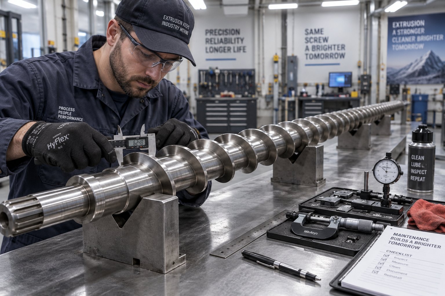
Screw and barrel wear is the slowest failure on an extrusion line — and the most expensive one to ignore. Every hour of operation removes microscopic amounts of material from the screw flight lands and the barrel bore. That wear gradually increases the clearance between the screw flight outer diameter and the barrel inner wall, allowing more polymer to slip backward over the flights instead of being pumped forward. The result is a progressive loss of pumping efficiency that operators unconsciously compensate for by increasing screw RPM — which accelerates the wear further.
Extruder screw and barrel wear measurement requires periodic physical inspection during planned shutdowns. For direct measurement, you'll check two critical dimensions:
- Flight OD clearance. A new screw typically runs with 0.002-0.004 inches of clearance per side against the barrel wall. Performance begins degrading noticeably around 0.006-0.010 inches. Once clearance exceeds 0.010-0.012 inches, output instability, melt temperature deviation, and dimensional problems become difficult to control through process adjustments alone.
- Metering channel depth. Wear on the screw root in the metering section reduces the effective channel depth, changing the pumping characteristics of the screw and altering the shear profile applied to the melt.
Between shutdowns, indirect indicators can tell you how the screw is performing without pulling it. Track the ratio of output rate (pounds per hour) to screw RPM over time. As the screw wears, this ratio declines — you need more RPM to achieve the same throughput. Predictive maintenance data shows that when operators have increased screw RPM by 15-20% above the original baseline to maintain output, it's time to pull the screw for measurement. Other indirect signals include melt temperature running progressively above barrel setpoints (worn flights generate more shear heat as material slips over them) and motor amperage changes at constant RPM.
When wear reaches replacement thresholds, partnering with a knowledgeable screw barrel supplier accelerates both diagnosis and resolution. NANHAIYA, for example, provides practical screw and barrel support for extrusion plants and recycling operations dealing with output instability, melt-quality problems, and pressure fluctuation — exactly the symptoms that worn screws produce. Having a trusted supplier who understands extrusion wear patterns means replacement components are specified correctly the first time, minimizing the downtime between screw pull and return to production.
Heater Band, Thermocouple, and Drive System Checks
Electrical and mechanical maintenance items may lack the drama of a worn screw, but they cause just as many misdiagnosed defects.
Heater band inspection. A failed heater band doesn't always announce itself with an alarm. Partial failures create subtle cold zones that neighboring heaters try to compensate for, distorting the temperature profile without triggering an obvious alert. During weekly downtime, inspect heater band terminals for discoloration, corrosion, or looseness. A corroded or loose terminal creates electrical resistance that increases current draw and accelerates heater failure. Also check that each band is seated firmly against the barrel surface — a loose band transfers heat poorly, overworks itself, and eventually burns out. Track heater duty cycles for each zone over time. A zone whose duty cycle creeps from the normal 40-70% range toward 85% or higher is signaling that its heater is approaching end of life.
Thermocouple verification. A drifting thermocouple is one of the sneakiest failure modes on the line. It sends a plausible but inaccurate signal to the temperature controller, which then adjusts heater output based on phantom readings. The displayed temperature looks fine, but the actual barrel wall temperature is wrong. If a zone's behavior doesn't match its displayed reading — the product shows signs of overheating or underheating that the screen doesn't reflect — swap the thermocouple before changing anything else. Periodic verification against a calibrated reference thermocouple catches drift before it causes product defects.
Gearbox and drive system monitoring. Unusual vibration, grinding noise, or elevated oil temperature from the gearbox all signal bearing wear or lubrication degradation. These problems don't affect the product immediately, but they eventually cause screw speed inconsistency that shows up as surging and dimensional variation. Check gearbox oil level and color weekly. Dark or foamy oil points to internal wear that will worsen. Monitor gearbox temperature under stable load monthly — a rising trend at the same operating conditions is an early warning that maintenance is needed before the gearbox forces a shutdown.
Building a Process Monitoring Baseline
Recording process monitoring baseline extrusion parameters is the single most powerful habit a production team can adopt. Without baseline data, every reading is just a number. With it, every reading becomes a trend — and trends reveal developing problems days or weeks before they produce scrap.
At regular intervals — daily for critical parameters, weekly or monthly for slower-moving indicators — log the following at standardized operating conditions:
- Melt temperature at the adapter
- Melt pressure at the adapter and/or die inlet
- Motor amps at the operating screw RPM
- Output rate in pounds per hour at a fixed screw speed
- Screw RPM required to achieve target output
- Heater duty cycles for each barrel zone
Set deviation thresholds so the team knows when a reading has moved far enough from baseline to warrant investigation. A practical tiered approach works well: a 10% deviation triggers an advisory note, 15-20% calls for active investigation, and anything beyond 25% demands immediate attention. Industry experience shows that predictive monitoring on extrusion lines typically delivers a 35-50% reduction in unplanned downtime within six months — not from complex technology, but from simply watching data streams that were always available.
The table below consolidates the key preventive maintenance items into a quick-reference format your team can use to build a structured schedule.
| Maintenance Item | Inspection Frequency | Warning Signs of Neglect | Impact on Product Quality |
|---|---|---|---|
| Screw and barrel clearance | Monthly measurement; full inspection during planned shutdowns | Output declining at same RPM; melt temperature running above setpoints; increasing motor amps | Surging; dimensional instability; melt inconsistency; increased scrap rate |
| Heater bands and terminals | Weekly visual and thermal inspection | Duty cycle exceeding 85%; discolored or loose terminals; zone temperature undershooting setpoint | Cold zones distort the temperature profile; surface defects; uneven melting |
| Thermocouples | Monthly verification against reference; replace on drift | Noisy temperature readings; controller hunting between heat and cool; zone behavior mismatching display | Phantom temperature control causes overheating or underheating; degradation or unmelt defects |
| Gearbox oil and bearings | Weekly oil level and color check; monthly temperature trend | Dark or foamy oil; unusual vibration or grinding noise; rising operating temperature at same load | Screw speed inconsistency; surging; eventual catastrophic failure and extended downtime |
| Screen pack and breaker plate | Monitor melt pressure rise rate continuously; change at 80% of maximum allowable pressure | Gradual pressure climb; reduced throughput at constant RPM; increasing head pressure alarms | Reduced output; pressure instability; risk of screen rupture contaminating the product |
| Process parameter baselines | Daily logging of melt pressure, temperature, motor amps, and output rate | No trend data available; operators relying on memory instead of records; same problems recurring without institutional learning | Problems caught late; longer diagnostic cycles; repeated scrap events from known failure modes |
The best troubleshooting is the kind you never have to do. Every hour invested in scheduled maintenance saves multiples in avoided scrap, emergency repairs, and lost production time.
Preventive maintenance shrinks the universe of problems that reach the production floor. But it doesn't eliminate them entirely. Some defects — persistent issues that survive systematic variable isolation, unexplained pressure behavior, or suspected material contamination — eventually exceed what any operator can resolve with floor-level adjustments. Knowing when that boundary has been reached, and exactly how to escalate efficiently, is the final critical skill in the troubleshooting toolkit.
When to Escalate and How to Get Expert Support Fast
Preventive maintenance and disciplined diagnostics resolve the vast majority of extrusion problems. But not all of them. Some defects persist after you've isolated every variable, walked every zone, and verified every thermocouple on the line. Continuing to adjust parameters at that point doesn't just waste time — it risks compounding the original problem with new ones introduced by speculative changes. Recognizing when to call an expert for extrusion problems is a skill, not a concession.
Signs a Problem Needs Expert-Level Diagnosis
How do you know when floor-level troubleshooting has reached its limit? Look for these patterns:
- Persistent defects after systematic variable isolation. You've followed the five-step methodology, changed one variable at a time, allowed the system to stabilize, and the defect remains unchanged or shifts character without resolving. This suggests the root cause lies outside the parameters you can adjust from the control panel — worn internal geometry, material contamination at a molecular level, or a design mismatch between the screw and the polymer being processed.
- Unexplained pressure or temperature behavior. Melt pressure drifts or oscillates in patterns that don't correlate with any feed, screw speed, or barrel temperature change. Temperature readings behave erratically even after thermocouple swaps. These symptoms often point to internal mechanical wear, hidden flow-path obstructions, or electrical issues that require instrumentation beyond what's available on the production floor.
- Suspected material contamination. Gels, specks, or splay defects that don't respond to purging, drying adjustments, or regrind isolation may indicate cross-contamination at the resin supplier level or degradation products embedded in barrel dead spots that only a full teardown can reveal.
- Potential equipment damage. Unusual noises from the gearbox, visible screw wobble, barrel discoloration from overheating events, or motor amp readings that have climbed well beyond baseline all signal mechanical conditions where continued operation risks turning a repairable problem into a catastrophic one.
The practical rule is straightforward: if you've made three systematic, single-variable adjustments targeting the most likely root cause and the defect hasn't improved, stop adjusting. Document what you've tried and escalate. Further guessing at this stage almost always makes the situation harder for the eventual expert to diagnose, because every additional change muddies the baseline.
The Pre-Call Documentation Checklist
When operators contact a supplier or specialist with a vague description — "the product looks bad" or "something changed" — diagnosis stalls before it starts. The single most effective thing you can do to accelerate expert-level support is to arrive with a complete extrusion troubleshooting escalation checklist already assembled. Having this package ready can cut diagnosis time from days to hours.
Before making the call, compile the following:
- Defect photos and samples. Capture clear images of the defect from multiple angles. If possible, save physical samples showing both the defective product and a "known good" sample from the last acceptable run for direct comparison.
- Complete process parameter record. List current barrel zone temperatures (setpoint and actual), die temperatures, screw RPM, melt pressure, melt temperature, motor amps, and line speed. Include the baseline values from before the problem started, if available.
- Material lot information. Record the resin supplier, grade, lot number, and any regrind blend ratio. Note whether the material lot changed recently — lot-to-lot variation in melt flow index or additive package is a surprisingly common trigger.
- Change history. Describe exactly what changed before the defect appeared: new material lot, screen pack change, die swap, maintenance event, shift changeover, or ambient temperature shift. Include timing — did the defect start immediately or develop gradually?
- Adjustments already attempted. List every parameter change you made, in sequence, and what effect each one produced. This prevents the expert from repeating steps you've already tried and helps them narrow the remaining possibilities.
- Melt pressure and motor amp trends. If your line logs these continuously, export or photograph the trend charts covering the period before, during, and after the defect appeared. Pressure and amperage patterns contain diagnostic information that snapshot readings miss.
This documentation habit does more than speed up a single support call. Over time, it builds the kind of institutional knowledge that helps your entire team recognize recurring patterns and intervene earlier on future issues — exactly the process monitoring baseline strategy outlined in the previous section.
Matching the Right Expert to the Problem Type
Not every extrusion problem goes to the same expert. Sending a die flow question to your resin supplier wastes their time and yours. Asking your electrician to diagnose melt fracture does the same. The key to how to document extrusion defects for technical support effectively is directing that documentation to the specialist whose expertise actually matches the defect category.
Use this resource map to route problems to the right partner:
- Screw and barrel specialists — For output instability, melt-quality inconsistency, pressure fluctuation, overheating, or any symptom that correlates with screw wear or barrel condition. NANHAIYA provides targeted screw barrel support for extrusion plants, recycling operations, and processing teams dealing with these exact issues. When your diagnostics point to worn flights, excessive clearance, or a screw design mismatch for the polymer being processed, a dedicated screw barrel specialist support for extruders is the fastest path to resolution.
- Material suppliers — For resin-related issues including suspected contamination, lot-to-lot MFI variation, additive incompatibility, or degradation behavior that doesn't match the polymer's published processing window. Your resin supplier has access to analytical labs that can test samples for molecular weight, moisture content, and contaminant identification.
- Die manufacturers — For flow distribution problems, persistent gauge variation, die lip damage, or land-length optimization questions. Die builders have the internal flow simulation data and machining capability to diagnose and correct channel geometry issues that no amount of process adjustment can fix.
- Controls and electrical technicians — For instrumentation failures including thermocouple drift that persists after replacement, PID controller tuning problems, heater circuit faults, or drive system irregularities. These specialists carry calibration equipment and diagnostic tools that go beyond the standard production floor toolkit.
The pattern across all four categories is the same: the more complete your documentation when you make the call, the faster the expert can isolate the problem. A screw barrel specialist who receives your melt pressure trend, output-per-RPM ratio, and motor amp history can often pre-diagnose whether wear is the issue before a site visit. A resin supplier who gets your lot numbers and defect photos alongside processing conditions can check their production records for known batch variations within hours.
The goal of escalation isn't to hand off the problem — it's to match it with the expertise that can resolve it fastest.
Effective plastic extrusion troubleshooting is never just one skill. It's a layered system — starting with a disciplined methodology, moving through symptom-based diagnosis, applying zone-by-zone and material-specific knowledge, maintaining equipment proactively, and knowing exactly when and how to bring in specialized support. Master each layer, and you'll spend less time chasing defects and more time running a production line that simply works.
Frequently Asked Questions About Plastic Extrusion Troubleshooting
1. What is the most common cause of surging in a single-screw extruder?
The most frequent cause of surging is improper temperature in the feed zone or on the screw surface. When the feed section runs too hot, pellets soften prematurely and lose the frictional grip needed for consistent forward conveyance. This creates a cyclic pattern where output drops, pressure falls, the controller compensates by increasing screw speed, and the cycle repeats. Before adjusting barrel temperatures or screw RPM, check whether the feed casing feels warm rather than hot, and verify that screw cooling water flow is within specification. Screw and barrel wear is the second most common driver — increased flight-to-barrel clearance reduces pumping efficiency in the metering zone, producing output instability that worsens progressively over time.
2. How do you fix melt fracture and shark skin defects in plastic extrusion?
Melt fracture and shark skin both originate from excessive shear stress at the die lip, though they differ in severity. Shark skin appears as fine, regularly spaced surface ridges, while melt fracture creates more chaotic, wavy distortions. The core corrective strategy is reducing shear rate at the die exit. Practical options include lowering screw speed to decrease volumetric throughput, raising melt temperature slightly to reduce polymer viscosity, widening the die gap to lower wall shear, or shortening the die land length. For persistent cases — especially with high-viscosity resins like HDPE — adding a fluoropolymer processing aid that promotes wall slip at the die surface can eliminate the defect without sacrificing output rate.
3. Why is pre-drying so critical for PET extrusion, and what happens if PET is not dried properly?
PET is highly hygroscopic and must be processed at a moisture content below 0.02% by weight. When wet PET enters the extruder, water molecules attack the polymer chains through hydrolysis almost instantly once the resin reaches melt temperature. This causes severe intrinsic viscosity (IV) loss, splay marks on the extrudate surface, internal bubbles, and haze in sheet or film products. Undried PET can lose more than half its viscosity, producing a melt too thin to control dimensionally. Proper drying typically requires temperatures of 120-150 degrees Celsius for approximately four hours using a desiccant dryer. Critically, dried PET re-absorbs enough ambient moisture to exceed safe thresholds in as little as 15 minutes, so feed systems must remain sealed against humidity.
4. How can you tell if an extrusion defect is caused by the die rather than the extruder barrel or screw?
Several diagnostic patterns point specifically to die-related root causes. Surface streaks or lines that remain fixed in position relative to the die — regardless of changes to screw speed or barrel temperature — indicate die land damage or buildup rather than upstream issues. Thickness variation that maps consistently to specific die zones instead of fluctuating randomly also implicates the die. Defects that worsen progressively during a run but improve immediately after die cleaning confirm material accumulation at the lip. Additionally, if product quality degrades only at high output rates while remaining acceptable at lower speeds, excessive shear stress at the die lip is the likely mechanism. When these patterns appear, resist adjusting barrel zones and begin your investigation at the die exit.
5. When should you stop troubleshooting on the production floor and call in an expert?
Escalation is warranted when you have followed a systematic, single-variable isolation approach and the defect persists after three targeted adjustments addressing the most probable root cause. Other clear escalation signals include melt pressure or temperature behavior that does not correlate with any process changes you have made, suspected material contamination that does not respond to purging or drying corrections, and mechanical warning signs such as unusual gearbox noise or abnormal motor amp readings. Before contacting a specialist, prepare a documentation package that includes defect photos, complete process parameter records with baseline comparisons, material lot information, a detailed change history, and melt pressure trend data. Directing this package to the right expert — such as a screw barrel specialist like NANHAIYA for output instability and wear-related issues, or your resin supplier for contamination questions — dramatically accelerates diagnosis and reduces downtime.
Written by
Nanhaiya Technical Team
Zhoushan Nanhaiya Plastic Machinery Co., Ltd.
The Nanhaiya technical team supports screw and barrel manufacturing projects through application review, technical communication, custom manufacturing coordination, and production and quality control.
Discuss Your Application
Related Articles
More insights on screw barrel technology and plastics processing.
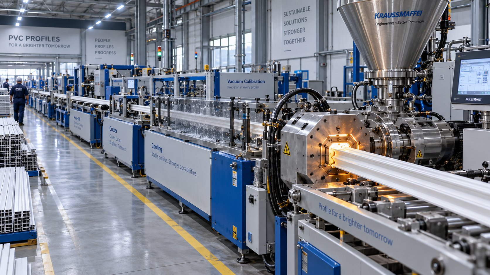
PVC Profile Extrusion Line Decoded: From Screw Design to Factory Floor
Oct 16, 2026
Learn how a PVC profile extrusion line works — from screw design and barrel profiling to troubleshooting, maintenance, and factory layout planning.
Read Article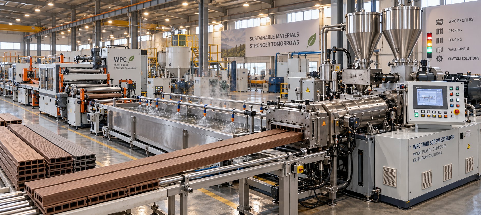
WPC Profile Extrusion Machine Decoded: Raw Blend To Flawless Profile
Oct 15, 2026
Learn how a WPC profile extrusion machine works — from extruder types and temperature zones to troubleshooting, wear management, and emerging co-extrusion trends.
Read Article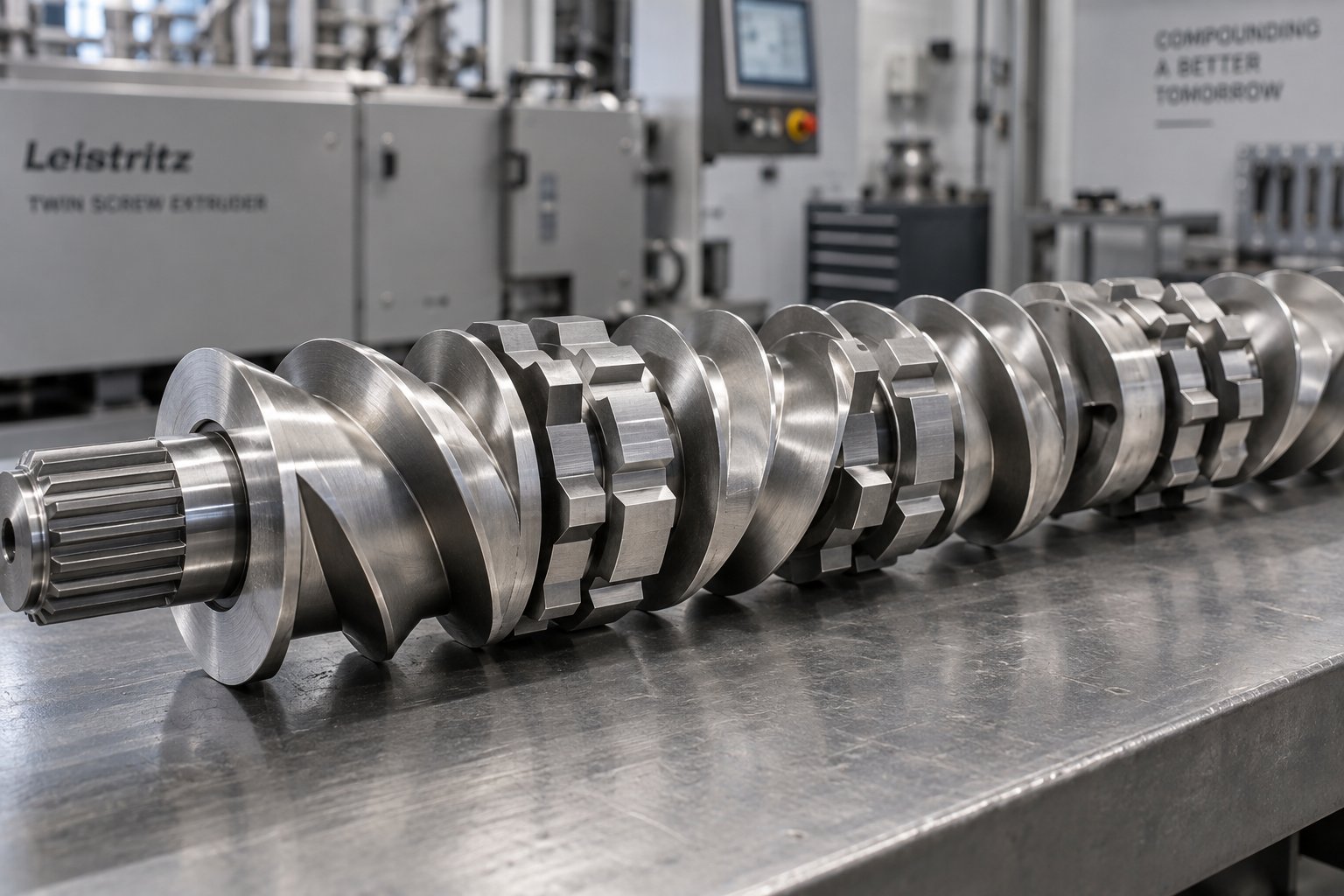
Twin Screw Extruder Screw Decoded: Geometry, Wear & Profile Fixes
Oct 14, 2026
Master twin screw extruder screw design: geometry parameters, kneading block stagger angles, element classification, wear mechanisms, and profile troubleshooting fixes.
Read ArticleLooking for something else?
Search by material, symptom or product and jump straight to the relevant page.
These are navigation suggestions based on keyword matching — not a quotation, not a delivery commitment, and not a substitute for engineering review. Final specification is confirmed by our engineers against your drawings and processed material.
Need help with screw barrel selection?
Share your machine model, processed material and application. Our team can help with pricing and technical support.