

What a PVC Profile Extrusion Line Is and Why It Matters
Imagine a single production system that transforms powdery raw compound into perfectly shaped window frames, cable trunking, skirting boards, and decorative trim — running continuously, meter after meter. That is exactly what a PVC profile extrusion line does. Yet calling it "just an extruder with a die" would be a serious oversimplification. The wrong configuration can lead to unstable dimensions, excessive scrap, and a line that never reaches its quoted output with your actual formulation. Getting the configuration right, on the other hand, means consistent conversion of PVC dry blend into saleable profiles at an acceptable cost per kilogram.
What Is a PVC Profile Extrusion Line
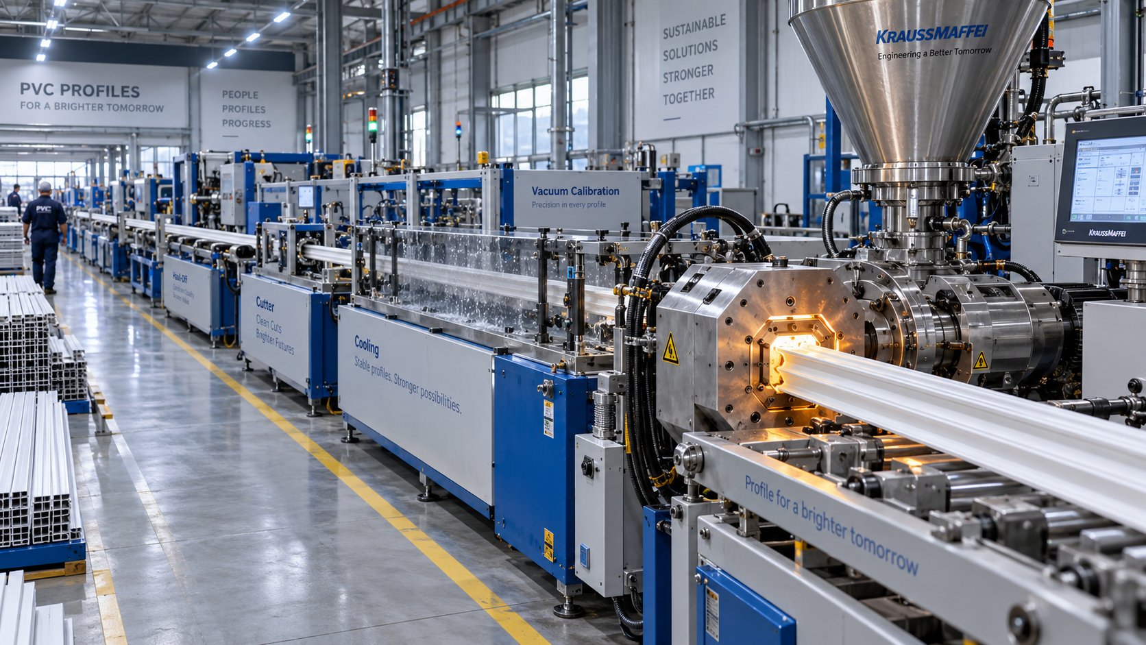
A PVC profile extrusion line is an integrated manufacturing system that melts, shapes, cools, and cuts rigid PVC compound into continuous cross-sectional profiles — such as window frames, wall panels, and electrical trunking — using a precisely coordinated sequence of upstream feeding, twin-screw extrusion, die forming, vacuum calibration, cooling, haul-off, cutting, and stacking equipment.
Every unit in the line plays a specific role, and they must work in tight synchronization. A mismatch between any two stages — say, extruder output and cooling capacity — creates bottlenecks that show up as dimensional drift, surface defects, or reduced line speed. That is why experienced manufacturers evaluate a PVC profile extrusion line as a complete system, not as a collection of individual machines.
Core Equipment in Every Profile Line
While configurations vary depending on the profile's complexity and production volume, you'll find these essential units on virtually every line:
- Hot-Cold Mixer: Disperses stabilizers, lubricants, impact modifiers, and pigments into PVC resin, then rapidly cools the blend to a free-flowing, storage-safe temperature.
- Twin-Screw Extruder: Plasticizes the dry-blended PVC powder into a homogeneous melt under carefully controlled temperature and shear conditions.
- Die Head: Shapes the molten PVC into the desired cross-sectional geometry, distributing melt flow evenly across the profile's walls and chambers.
- Vacuum Calibration Tank: Locks the still-soft extrudate into its final dimensions by drawing it against precision-machined sizing sleeves under vacuum.
- Cooling Bath: Removes residual heat from the profile through spray or immersion cooling, solidifying the PVC throughout the full wall thickness.
- Haul-Off Unit: Grips the cooled profile and pulls it through the downstream line at a constant, synchronized speed without marking or deforming the surface.
- Cutting Saw: Slices the continuous profile into specified lengths, often with swarf extraction to keep surfaces clean.
- Stacking or Tilting Table: Collects, organizes, and prepares finished lengths for packaging or palletizing.
A thin wall panel and a multi-chamber window frame may both be made from rigid PVC, yet they impose very different demands on melt distribution, calibration, cooling residence time, and haul-off force. Output, therefore, needs to be evaluated in both kilograms per hour and meters per minute — a high kg/h figure means little if the cooling section cannot stabilize the profile at the required line speed.
Why PVC Dominates Profile Applications
When you compare PVC against alternatives like ABS or ASA for construction profiles, a few advantages stand out. PVC offers inherent flame retardancy without the need for additional flame-retardant additives — a critical factor for building codes. Its weatherability, especially when paired with modern stabilizer systems, allows exterior profiles to resist UV degradation and color shift over decades of service. And on a cost-per-meter basis, PVC remains highly competitive, which is why it continues to dominate fenestration, trunking, and trim markets worldwide.
Here is the engineering challenge that makes PVC profile extrusion uniquely demanding: PVC has a narrow thermal processing window and high shear sensitivity. Push temperatures or screw speeds too high and the polymer degrades, releasing hydrochloric acid and discoloring the product. Run too cool and the melt remains poorly plasticized, producing rough surfaces and weak weld lines. This delicate balance between sufficient plasticization and thermal degradation is the central thread running through every equipment decision — from screw geometry and barrel zoning to die design and downstream cooling — explored in the sections ahead.
How the PVC Profile Extrusion Process Works Stage by Stage
That delicate balance between sufficient plasticization and thermal degradation doesn't manage itself — it's maintained through a tightly choreographed sequence of processing stages, each one handing off to the next with very little margin for error. Understanding the pvc extrusion process from start to finish gives operators and engineers the ability to trace a defect back to its origin rather than guessing. Here's what physically happens to a PVC compound as it travels from raw powder to finished profile.
Dry Blending and Material Feeding
Every successful run begins long before the extruder starts turning. PVC resin must be pre-blended with stabilizers, lubricants, impact modifiers, pigments, and processing aids in a hot-cold mixer system. During the hot mixing stage, high-speed shear and friction raise the compound temperature — typically to between 110°C and 130°C for rigid PVC dry blend — opening the resin pores so additives are absorbed rather than simply sitting on the surface. The batch then discharges into a cooling mixer, which rapidly brings it below 40°C to 45°C. This rapid cooling locks in the additive dispersion, prevents premature stabilizer depletion, and delivers a free-flowing powder that feeds consistently into the extruder hopper.
Why does this matter so much? If the dry blend arrives at the extruder at an inconsistent temperature or with uneven additive dispersion, you'll see die pressure variation, shifting extrudate color across a shift, and clumping in the feed hopper that causes surging. In other words, extrusion problems that look like machine issues often trace back to the mixing room. From the hopper, the blended powder enters the extruder feed throat — usually through a gravimetric or volumetric dosing system — where it meets the screws for the first time.
Plasticization and Melt Conveyance Through the Barrel
Inside the barrel, the screw geometry does the heavy lifting. Picture the process in three functional zones. In the feed zone, the wide screw flights accept the low-bulk-density PVC powder and begin compacting it forward. As the material advances into the compression zone, the decreasing channel depth subjects the powder to increasing pressure and shear, converting it from a loose aggregate into a dense, partially fused mass. Finally, in the metering zone, the fully plasticized melt is homogenized and delivered at a consistent pressure toward the die.
The critical parameters to watch during this stage are melt temperature, melt pressure at the barrel tip, and motor amperage. Melt temperature that climbs too high signals excessive shear or overheated barrel zones — both dangerous for a polymer as thermally sensitive as PVC. Unstable melt pressure, on the other hand, points to inconsistent feeding, worn screw flights, or poor dry blend quality. Experienced operators monitor these readings continuously because the barrel is where the plastic profile extrusion process either succeeds or starts generating scrap.
Die Shaping and Vacuum Calibration
As the homogeneous melt exits the barrel, it enters the die head — a precision-machined steel tool that distributes the melt into the profile's cross-sectional shape. Flow channels, choke bars, and restrictor pins inside the die balance the melt velocity so that thin walls, thick flanges, and hollow chambers all fill evenly. An imbalanced die produces profiles with uneven wall thickness, internal stresses, and a tendency to warp after cooling.
The extrudate leaves the die lip hot and dimensionally unstable. Within centimeters, it enters the vacuum calibration tank — and this is where the profile's final dimensions are literally locked in. Inside the calibrator, precision-machined sizing sleeves surrounded by vacuum ports draw the soft extrudate against their inner surfaces, holding it in the correct shape while cooled steel and water remove heat. Calibration sizing uses both vacuum and water cooling simultaneously: the vacuum ensures intimate contact between the profile and the sizing sleeve, while the cooling water solidifies the PVC rapidly enough to hold that shape. Hollow profiles are particularly demanding because heat can only be extracted through the outer walls; the inner surfaces reheat as residual thermal energy migrates outward, often requiring multiple calibrator sections to maintain dimensional stability.
Operators monitor vacuum level, water temperature, and the gap between the die lip and calibrator entrance. Even a small misalignment here can produce asymmetric wall thickness or surface drag marks.
Cooling, Haul-Off, and Cutting
After the calibrator, the profile still retains significant internal heat, especially in thick-walled or multi-chamber designs. It passes through one or more spray or immersion cooling baths that continue extracting thermal energy until the PVC has solidified through the full wall section. Water flow within these baths must remain steady — turbulence can cause the extrudate to shift and vacillate in size, so the first cooling compartment typically uses a controlled, laminar flow while subsequent sections may increase turbulence for faster heat transfer.
The haul-off unit grips the cooled profile with rubber-padded belts or caterpillar tracks and pulls it through the entire downstream line at a precisely controlled speed. Haul-off speed relative to screw output determines the degree of drawdown — pull too fast and wall thickness drops below specification; too slow and the profile swells or buckles. For rigid PVC profiles, this ratio must stay extremely tight because high drawdown and orientation can cause brittleness and dimensional instability.
Finally, the continuous profile reaches the cutting saw — typically a flying saw that travels with the profile to produce clean, burr-free cuts at programmed lengths without stopping the line. The cut pieces then transfer to a stacking table or automated tilting rack for inspection and packaging.
Each of these stages is only as strong as the one before it. A perfectly tuned downstream section cannot compensate for a poorly plasticized melt, and even flawless barrel performance is wasted if the die distributes flow unevenly. That interdependence is exactly why the choice of extruder architecture — the machine at the heart of the entire line — carries such outsized importance for PVC profile production.
Choosing the Right Extruder Architecture for PVC Profiles
That outsized importance is no exaggeration. The extruder dictates how gently — or aggressively — your PVC compound is plasticized, and for a polymer that degrades when overworked, "gentle" isn't a luxury. It's a requirement. Three fundamental extruder architectures compete for this role: conical twin-screw, parallel twin-screw, and single-screw. Each brings a different mechanical philosophy to the task, and selecting the wrong one for your application means fighting your own pvc profile extrusion machine every shift.
Conical Twin-Screw Extruders and Their PVC Advantage
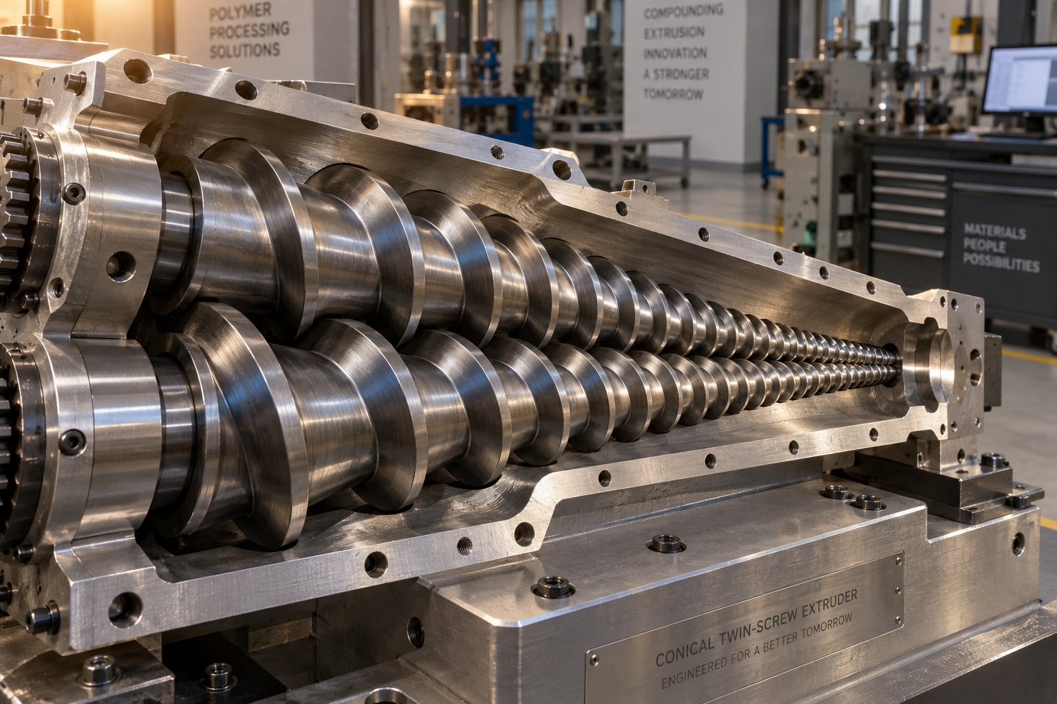
Picture two tapered screws sitting side by side inside a barrel shaped like a narrow V. The feed end is wide — wide enough to swallow low-bulk-density PVC powder without bridging or starving. As the screws rotate and intermesh, the channel depth gradually decreases toward the discharge end, compressing and plasticizing the compound through a naturally increasing compression ratio. This tapering geometry is the core reason conical twin-screw designs dominate profile extrusion plastic manufacturing for rigid PVC.
What makes this so effective? Three things work in your favor simultaneously. First, the large feed-zone cross section accommodates the fluffy, aerated dry blend that PVC formulations typically produce — no need for force-feeding or pre-densification. Second, the gradual compression builds pressure slowly, generating far less frictional shear heat than an abrupt transition would. For a polymer that starts degrading only a few degrees above its processing window, that low shear environment is critical. Third, the intermeshing, co-rotating or counter-rotating flight design provides a self-wiping action that prevents stagnant melt pockets — dead zones where PVC would overheat, char, and eventually contaminate your product with black specks.
The result is a homogeneous melt delivered at stable pressure and temperature, which is exactly what a complex multi-chamber die demands. Specialist manufacturers like NANHAIYA produce custom and replacement conical twin screw barrels engineered specifically for stable PVC plasticizing. For profile extrusion manufacturers that require precise barrel-screw matching to maintain consistent melt quality across long production runs, this kind of specialist support becomes essential — particularly when original components begin to wear and output consistency starts to drift.
Parallel Twin-Screw and Single-Screw Alternatives
Does every application need a conical design? Not necessarily. Parallel twin-screw extruders use two same-diameter screws running side by side. They excel in high-throughput compounding and large-diameter pipe extrusion where output volume matters more than gentle processing. However, their higher shear rates and the fact that they are better suited for pre-compounded pellets rather than raw powder blends make them a less natural fit for complex profile geometries in rigid PVC.
Single-screw extruders, meanwhile, occupy a narrower niche in the PVC profile world. You'll find them handling co-extrusion cap layers — thin ASA or acrylic skins applied over a PVC core for enhanced UV resistance — or processing recycled PVC pellets where the material has already been compounded once. Their simpler design reduces capital cost, but the limited mixing capability and lower feed acceptance for powder blends mean they rarely serve as the primary plastic profile extrusion machine on a rigid PVC line.
The table below puts all three architectures side by side so you can match each design to your specific production scenario:
| Feature | Conical Twin-Screw (e.g., NANHAIYA Conical Twin Screw Barrel) | Parallel Twin-Screw | Single-Screw |
|---|---|---|---|
| Feed Capability | Excellent for low-bulk-density PVC powder; large feed-zone intake prevents bridging | Better suited for pre-compounded pellets or densified powders | Limited powder handling; best with pellets or pre-densified feedstock |
| Shear Sensitivity | Low shear heat generation — ideal for thermally sensitive rigid PVC | Higher shear; risk of thermal degradation with raw PVC powder at elevated speeds | Moderate shear; limited self-wiping increases dead-zone risk for PVC |
| Throughput Range | Typically 150–800 kg/h depending on screw diameter (e.g., SJSZ-51 to SJSZ-92 models) | High output potential; commonly used for large-diameter pipe and pelletizing lines | Lower output in PVC applications; primarily used for co-extrusion layers |
| Typical PVC Profile Applications | Window frames, door profiles, multi-chamber trunking, decorative trim, WPC profiles | Large rigid pipe, high-volume pelletizing, sheet extrusion | Co-extrusion cap layers (ASA/acrylic), recycled PVC reprocessing |
| Self-Wiping Action | Superior intermeshing design eliminates stagnant melt pockets | Good self-wiping but higher thermal load offsets the benefit for sensitive PVC | No intermeshing; higher risk of material hang-up and degradation |
For the vast majority of rigid PVC profile production — window systems, cable management trunking, cladding, and architectural trim — the conical twin-screw extruder remains the proven standard. Its geometry was essentially designed around PVC's unique processing constraints, and that purpose-built match is difficult to replicate with alternative architectures.
Selecting the right extruder architecture, however, is only half the equation. The performance you extract from any of these designs depends heavily on two interrelated variables that most equipment discussions overlook: the screw's length-to-diameter ratio and the temperature profile you program into each barrel zone.
Screw L/D Ratio Selection and Barrel Temperature Profiling
Two variables quietly shape everything your extruder can — and cannot — deliver: how long the screw is relative to its diameter, and how you distribute heat across the barrel zones. Get either one wrong, and even the best conical twin-screw architecture will produce inconsistent melt quality, dimensional drift, or worse — degraded PVC that contaminates an entire shift's output. These parameters rarely get the attention they deserve in equipment discussions, yet they are the levers operators and engineers reach for first when fine-tuning a pvc extrusion line.
How Screw L/D Ratio Affects Melt Quality and Throughput
L/D ratio — length-to-diameter ratio — is simply the working length of the screw divided by its nominal diameter. A conical twin-screw extruder with a screw length of 660 mm and a large-end diameter of 55 mm, for example, has an L/D of roughly 12:1. Sounds like just a number, but it controls two competing forces: how thoroughly the PVC compound is mixed and plasticized, and how long that heat-sensitive material stays inside a hot barrel.
A longer barrel — higher L/D — gives the compound more residence time. More time means more opportunity for the screw flights to shear, compress, and homogenize the melt. For compounds with heavy filler loading or complex additive packages, that extra mixing can be the difference between a well-fused, glossy profile and one riddled with unmixed particles. However, PVC doesn't reward extended thermal exposure the way polyolefins might. Every additional second inside the barrel is another second of heat history, pushing the compound closer to the edge of its narrow processing window.
Conical twin-screw extruders used for extrusion profile pvc typically operate in an L/D range of roughly 22:1 to 28:1 (measured at the larger feed-end diameter). Parallel twin-screw designs, with their uniform diameter, commonly reach L/D values of 28:1 to 36:1 or higher — which partly explains their higher shear input and the additional thermal management challenges they present for rigid PVC.
What actually happens at the extremes? Consider these practical consequences:
- When L/D is too short: The compound doesn't receive enough shear and heat to fully plasticize. Operators see incomplete fusion — rough surface texture, poor weld-line strength in multi-chamber profiles, and visible unmelted particles in cross-sections. Melt pressure fluctuates because the screw simply cannot build a consistent, homogeneous flow in the available length. Increasing screw speed to compensate only introduces more frictional heat in a concentrated zone, risking localized degradation rather than solving the mixing deficit.
- When L/D is too long: Residence time increases beyond what PVC can tolerate safely. The compound absorbs excessive thermal energy, stabilizer reserves deplete faster, and the risk of degradation — yellowing, black specks, and hydrochloric acid release — climbs with every degree and every second. You may also notice higher motor amperage because the longer barrel creates more drag on the melt. Output per RPM may actually decline as the overworked polymer loses viscosity from thermal breakdown, collapsing the very melt pressure stability the longer barrel was supposed to improve.
The sweet spot for most rigid PVC profile applications falls comfortably within the conical twin-screw range. These machines achieve adequate plasticization without the thermal penalty of excessively long barrels — a deliberate engineering compromise built into their tapered geometry.
Setting Up a Barrel Temperature Profile for PVC
If L/D ratio determines how much processing the compound receives, the barrel temperature profile determines the thermal pathway it follows. Imagine the barrel as a series of independently heated and cooled zones — typically four to six — each set to a different target temperature. The pattern you choose across these zones has a direct, measurable impact on fusion quality, surface finish, and whether your stabilizer package survives the trip from hopper to die.
The governing principle for pvc extrusion is straightforward: start low, rise gradually, then pull back slightly before the die. Here's the logic behind each segment.
In the feed zone, temperatures are kept deliberately low. The goal here is not to melt the PVC powder but to compact and convey it forward reliably. Setting this zone too hot causes premature softening — the powder sticks to the barrel wall and screw flights, reducing conveying efficiency and starving downstream zones. A cooler feed zone preserves the powder's ability to be gripped and pushed forward by the screw geometry.
Temperatures increase through the compression zone, where the real work of plasticization happens. As channel depth decreases and pressure builds, frictional heat from the intermeshing screws combines with conducted heat from the barrel wall. The compound transitions from a loose powder aggregate into a dense, partially fused mass and eventually into a fully plasticized melt. The temperature rise across this zone should be gradual — sudden jumps create thermal shocks that degrade PVC at the barrel surface while leaving the core of the melt channel underfused.
The metering zone and die adapter represent a subtle but critical shift. Here, barrel temperatures are typically held steady or reduced slightly from the compression zone peak. Why the decline? By this point, the melt is fully plasticized. Additional heat offers no processing benefit — it only accelerates stabilizer consumption and pushes the compound toward degradation. The slight temperature reduction in the metering zone helps stabilize melt viscosity and pressure, delivering a consistent, thermally balanced flow into the die head. The die itself is then set to a temperature that ensures smooth surface quality and correct dimensional filling without overheating the melt in the flow channels.
The ideal PVC barrel temperature profile follows a rising-then-declining curve: cool feed zone, progressively warmer compression zone, and a metering zone that holds steady or drops slightly before the die adapter.
Overheating at any point in this sequence triggers a cascade of problems. Thermal degradation in PVC releases hydrochloric acid, which not only discolors the product — producing brown streaks or black specks — but also corrodes barrel and screw surfaces, accelerating wear and further destabilizing the process. Conversely, running barrel zones too cold starves the melt of the energy it needs for complete fusion, resulting in rough surfaces, poor mechanical properties, and a profile that may look acceptable on the line but fails impact testing downstream.
Operators monitoring a running line should pay close attention to the relationship between barrel set temperatures and actual melt temperature measured at the barrel tip or die adapter. A growing gap between the two — where melt temperature significantly exceeds the set point — typically indicates excessive shear heating from worn screws, an overly aggressive compression ratio, or a screw speed that has crept beyond the compound's tolerance. That gap is often the earliest warning sign that something in the process has shifted.
Dialing in L/D ratio and temperature profile is essential, but these variables don't exist in isolation. The compound arriving at the extruder — its formulation, its additive loading, and the consistency of the dry blend — ultimately dictates how the screw and barrel must be configured. The upstream preparation stage is where that story begins.
Raw Material Preparation and Feeding Systems Explained
A perfectly configured extruder with flawlessly tuned barrel zones still cannot rescue a poorly prepared dry blend. The compound arriving at the feed throat carries with it every mixing error, every inconsistent additive dispersion, and every temperature deviation from the blending room. In many PVC profile production lines, upstream preparation is treated as a supporting act — when in reality, it's the foundation that determines whether your extrusion process runs smoothly or fights itself from the first revolution of the screw.
Hot-Cold Mixing Requirements for PVC Dry Blend
Why can't you simply pour raw PVC resin, a stabilizer, some lubricant, and a handful of pigment into the extruder hopper and let the screw sort it out? Because PVC resin in its virgin state is a porous powder that needs its additives absorbed into the particle structure — not just dusted onto the surface. That absorption requires heat, controlled shear, and precise sequencing.
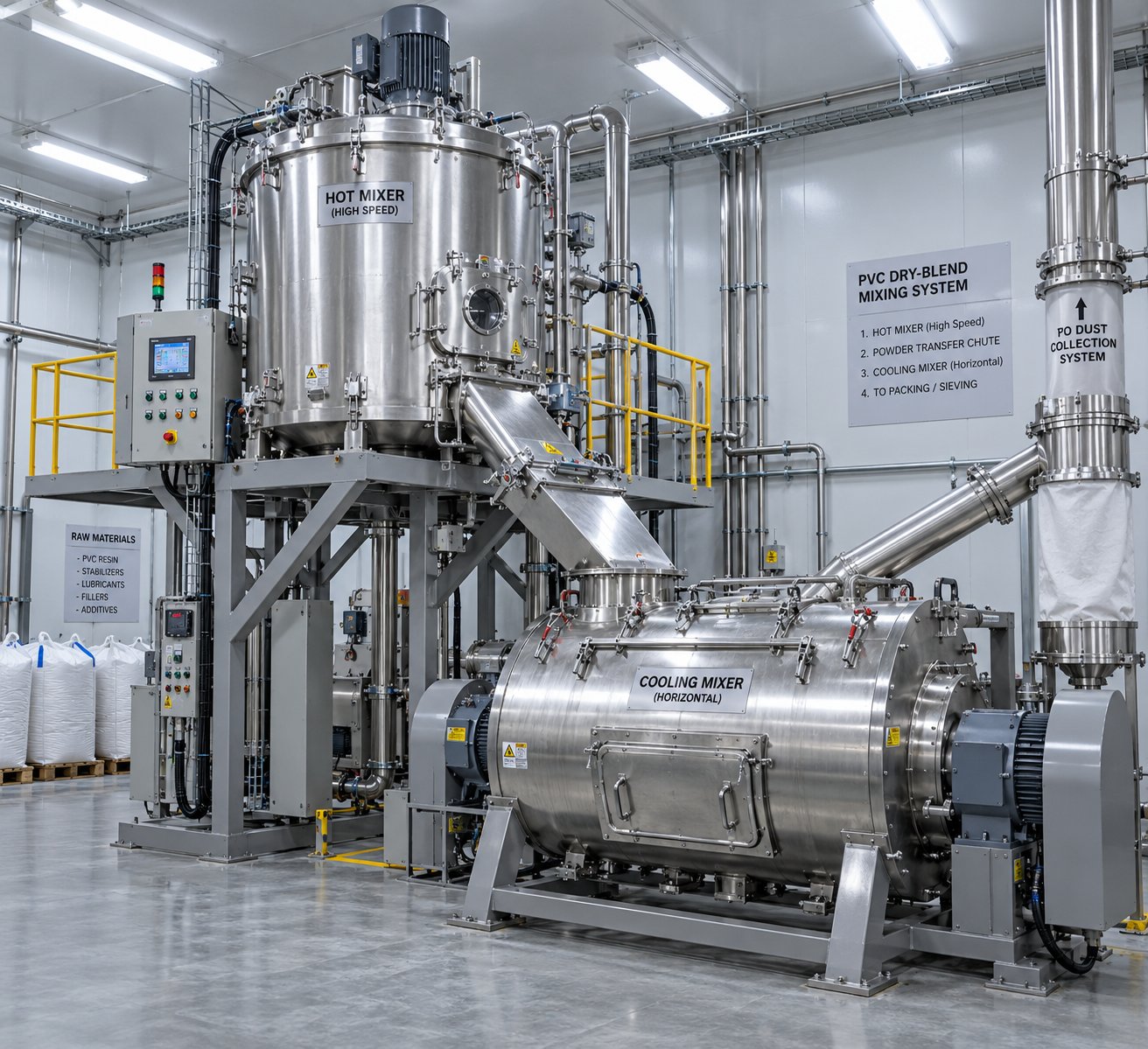
The process starts in the hot mixer — a high-speed, high-intensity vertical mixing chamber. PVC resin is charged first, followed by the thermal stabilizer, then lubricants, processing aids, impact modifiers, fillers such as calcium carbonate, and finally pigments. The order matters: stabilizers must coat the resin before other additives compete for surface area. As the mixer blades rotate at high speed, friction and mechanical energy raise the compound temperature. For rigid PVC dry blends, this typically reaches around 110°C to 130°C — hot enough to open the resin's pore structure and allow plasticizer-free additives to be absorbed into the particle rather than simply clinging to its exterior. B&P Littleford notes that heating PVC resin to approximately 200°F causes it to expand and absorb added components, producing a dry, free-flowing powder that feeds consistently into downstream equipment.
Once the hot mix cycle is complete — usually around 10 to 20 minutes depending on batch size and formulation — the batch discharges into the cold mixer. This is a large, slow-speed horizontal or vertical cooler that rapidly brings the compound temperature below 40°C to 45°C. Rapid cooling is not optional: it locks in the additive dispersion, prevents premature stabilizer depletion from prolonged heat exposure, and ensures the resulting dry blend flows freely without clumping in storage silos or feed hoppers.
Imagine skipping this cooling step. The warm powder would compact inside storage vessels, bridge at the hopper throat, and feed erratically into the extruder — causing the very melt pressure fluctuations and dimensional drift that operators spend hours trying to troubleshoot downstream. Consistent dry blend quality is the single most undervalued factor in pvc profile machine performance. When extrusion problems appear random and resist every machine-side adjustment, the mixing room is almost always where the real answer hides.
Gravimetric Versus Volumetric Feeding Systems
After blending and cooling, the dry blend must reach the extruder's feed zone in a controlled, repeatable manner. Two feeding philosophies compete here: volumetric and gravimetric. Both work, but they serve different accuracy and cost requirements.
A volumetric feeder delivers material based on volume — essentially a screw or auger turning at a set speed, pushing a fixed volume of powder per revolution into the hopper. It's simple, reliable, and cost-effective. The catch? It assumes constant bulk density. If your dry blend absorbs moisture between shifts, settles during storage, or varies slightly from batch to batch, the actual mass delivered per revolution drifts — and your finished profile's weight-per-meter drifts with it.
A gravimetric feeder, by contrast, measures actual mass in real time using load cells. The control system continuously adjusts screw speed to maintain the target feed rate regardless of changes in bulk density, powder flow behavior, or hopper fill level. You'll pay more upfront, but the payoff shows up directly in tighter weight-per-meter control, reduced material waste, and more stable melt pressure at the die — all critical for a plastic profile production line producing profiles that must meet strict dimensional and weight tolerances.
| Feature | Gravimetric Feeder | Volumetric Feeder |
|---|---|---|
| Accuracy | High — typically +/- 0.5% or better by weight | Moderate — dependent on constant bulk density; typically +/- 1% to 2% |
| Cost | Higher initial investment due to load cells and control electronics | Lower capital cost; simpler mechanical design |
| Bulk Density Sensitivity | Self-compensating — adjusts in real time for density variation | Highly sensitive — output varies with any density change |
| Weight-per-Meter Control | Excellent — enables closed-loop consistency in finished profiles | Adequate for less critical applications with stable compounds |
| Best-Use Scenarios | Multi-chamber window profiles, co-extruded systems, tight-tolerance trunking, any line requiring traceable production data | Simple trim profiles, single-wall extrusions, applications where slight weight variation is acceptable |
| Integration with Automation | Easily integrated with PLC and recipe management systems for data logging | Limited feedback; typically manual speed adjustment |
For any pvc profile production line running multi-chamber window frames or profiles subject to certification testing, gravimetric feeding is effectively a necessity. The real-time mass data it generates also feeds into broader production tracking and OEE systems — a benefit that compounds as operations scale.
How Compound Formulation Drives Machine Specification
Here's a connection that often gets overlooked during equipment selection: the recipe you run doesn't just affect product properties — it directly influences the mechanical specification of the machines processing it. Change your formulation and you may need to change your hardware.
Consider stabilizer systems. The shift from lead-based to calcium-zinc stabilizers, driven by regulatory pressure across Europe and increasingly worldwide, changes the compound's fusion behavior and thermal processing window. Calcium-zinc systems often require tighter temperature control and may alter lubricant balance, demanding more precise barrel zone profiling. Incorrect stabilizer dosage can cause yellowing, brittleness, and insufficient thermal stability during extrusion — problems that no downstream adjustment can correct.
Filler loading is another formulation variable with direct mechanical consequences. Calcium carbonate at moderate levels improves stiffness and reduces raw material cost. Push the loading higher — say, above 15 to 20 parts per hundred resin — and you'll accelerate screw and barrel wear significantly. The abrasive filler particles act like fine sandpaper against flight surfaces and barrel bores, shortening replacement intervals and potentially justifying bimetallic barrel linings or hardened screw coatings.
Impact modifier levels affect melt viscosity and die flow behavior. Higher CPE or acrylic modifier content improves toughness in the finished profile but also changes the compound's rheology, potentially requiring adjustments to die geometry, land length, and flow channel balance to maintain even wall distribution across complex cross sections.
In short, every formulation decision ripples through the entire line — from the mixer's cycle time and the feeder's accuracy requirement, through the screw's wear rate and compression characteristics, all the way to the die's flow channel design. Treating compound development and machine specification as separate conversations is one of the most common — and most costly — mistakes in plastic profile production line planning.
These upstream choices define what the extruder receives. But the intelligence built into the line itself — its sensors, control loops, and data systems — determines how precisely the process responds when conditions inevitably shift during production.
Automation and Smart Controls in Modern Extrusion Lines
Conditions on any profile extrusion line never stay perfectly static. Ambient temperatures shift between morning and afternoon. A new dry blend batch arrives with a slightly different bulk density. A vacuum pump gradually loses efficiency. In a manually controlled line, these disturbances accumulate silently — meter after meter of profile drifting away from target specification — until an operator notices, investigates, and corrects. By that point, hundreds of meters of out-of-spec product may already be on the stacking table. Modern automation doesn't eliminate disturbances. It detects and corrects them faster than any human operator could.
Smart Controls and Closed-Loop Quality Systems
At the heart of every modern plastic profile extrusion line sits a PLC (programmable logic controller) paired with an HMI (human-machine interface) touchscreen. The PLC executes the logic — receiving sensor data, comparing it against target values, and sending correction signals to motors, heaters, and pumps. The HMI gives operators a visual window into that logic: real-time trend graphs, alarm notifications, recipe parameters, and diagnostic screens that turn abstract process data into actionable information.
What makes this architecture genuinely powerful, though, is the closed-loop feedback it enables. Instead of relying on periodic manual checks, sensors positioned at critical points along the line continuously feed data back to the PLC, which automatically adjusts process parameters to maintain target specifications. Rollepaal highlights the fundamental distinction: a reactive extrusion line depends on correction after variation appears, while a controlled line detects variation early and corrects automatically. In practical terms, the line becomes self-correcting rather than merely operator-corrected.
Here are the key sensors and what each monitors in a typical closed-loop profile extrusion line:
- Melt pressure transducers (barrel tip and die adapter): Monitor pressure stability in real time, flagging feeding irregularities, screw wear, or die blockages before they produce visible defects.
- Melt temperature thermocouples (multiple barrel zones and die): Track actual melt temperature against set points, detecting excessive shear heating or zone controller faults.
- Ultrasonic or laser wall-thickness gauges (post-calibration): Measure profile wall dimensions continuously, enabling automatic haul-off speed adjustment to hold thickness within tolerance.
- Vacuum level sensors (calibration tank): Ensure consistent vacuum draw for dimensional stability; drops signal pump wear or seal leaks.
- Motor amperage and torque monitors (extruder drive): Reveal changes in melt viscosity or compound consistency that would otherwise go unnoticed until defects appear.
- Gravimetric feed rate sensors (hopper and feeder): Verify actual mass throughput, automatically compensating for bulk density variation in the dry blend.
When these sensors work in concert, the result is impressive. Imagine the wall-thickness gauge detects a 0.1 mm drift on one flange of a multi-chamber window profile. The PLC instantly adjusts haul-off speed — or, in more advanced systems, sends a correction signal to the die's thermal centering zones — pulling dimensions back to target within seconds. This kind of automatic correction is what separates a line that produces consistently saleable output from one that relies on an operator's attention span across a ten-hour shift.
Energy Efficiency and Drive Technology Choices
Automation isn't only about quality — it directly impacts operating cost. The extruder drive motor is the single largest energy consumer on any extrusion line, and the technology behind that motor determines how efficiently electrical energy converts into useful plasticizing work.
Traditional AC induction motors with fixed-speed drives or basic variable frequency drives (VFDs) have served the industry for decades. They're robust and well understood. However, they waste energy at partial loads — running the motor at reduced speed doesn't proportionally reduce power draw because of inherent motor losses. For a line that frequently adjusts screw RPM or runs different profile recipes at varying outputs, those losses add up shift after shift.
Servo-driven extruders change the equation. Servo motors deliver torque precisely on demand, with significantly higher efficiency at partial loads and during acceleration or deceleration cycles. They also offer superior speed control resolution, meaning the PLC can make finer, more responsive adjustments to screw RPM — which directly benefits melt pressure stability and, by extension, dimensional consistency. Many manufacturers report meaningful reductions in kWh per kilogram of output after retrofitting or upgrading to servo-driven systems, with the exact savings depending on line utilization, product mix, and the baseline efficiency of the equipment being replaced.
Beyond the main drive, servo technology extends to haul-off units and cutting saws, where precise speed and position control reduce mechanical wear and improve cut accuracy. Across the full line, these incremental efficiency gains compound into a lower cost-per-meter figure that strengthens margins on every profile produced.
Data Logging and Production Optimization
Sensors and closed-loop control handle the moment-to-moment corrections. Data logging captures the bigger picture — the trends, patterns, and recurring issues that only become visible over days, weeks, and months of production history.
Modern extrusion lines record every critical parameter — melt temperatures, pressures, screw speed, haul-off speed, vacuum levels, motor loads, and dimensional measurements — timestamped and stored in a central database. This data serves multiple purposes simultaneously:
- OEE (Overall Equipment Effectiveness) tracking: Quantifies how much of your scheduled production time actually produces saleable product, breaking losses into availability, performance, and quality categories so you can target improvements where they matter most.
- Alarm histories: Create a searchable record of every process excursion, enabling engineers to correlate recurring defects with specific upstream events — a particular dry blend batch, a time of day, or a gradual sensor drift.
- Recipe management: Stores validated process parameters for each profile type, ensuring that a recipe producing good results on Tuesday can be recalled exactly on Thursday — regardless of which operator is running the shift.
- Traceability: Links every meter of finished profile to the process conditions under which it was produced, supporting quality audits, customer complaints resolution, and regulatory compliance documentation.
The shift here is cultural as much as it is technological. A plant running with data logging moves from reactive troubleshooting — "something went wrong, let's figure out what" — to proactive optimization: "this trend is developing, let's correct it before it costs us." That proactive stance, supported by the right sensor infrastructure and control logic, is what transforms a standard extrusion line into a genuinely smart manufacturing cell.
All of this intelligence, however, cannot prevent the physical reality of wear. Sensors degrade, calibration drifts, and — most critically — the mechanical components at the core of the process slowly lose the precision they were built with. Knowing what to look for when things start going wrong, and how to trace a finished-product defect back to its root cause, is where operational expertise meets engineering discipline.
Troubleshooting Common PVC Profile Extrusion Defects
Sensors flag deviations, control loops apply corrections, and data logs capture trends — yet defects still appear. A faint roughness develops on the profile surface midway through a shift. A window frame flange starts measuring 0.15 mm thinner than it did an hour ago. A subtle brown streak appears along an interior chamber wall. Each of these symptoms tells a specific story about what went wrong and where. The difference between a production team that loses hours chasing ghosts and one that resolves issues in minutes comes down to one skill: reading the defect correctly before touching any settings.
The most costly troubleshooting mistakes happen when operators adjust multiple variables at once — changing barrel temperature, screw speed, and haul-off simultaneously — before identifying the defect category. As extrusion troubleshooting specialists emphasize, the fastest path to resolution follows three steps: name the visible defect, locate the station where it first appears, and make one controlled correction at a time. Stacking changes creates delayed responses that mask the real cause and introduce new instability. With PVC extrusion profiles, this disciplined approach matters even more because the polymer's thermal sensitivity means overcorrecting in one direction can trigger degradation that far outweighs the original problem.
Surface Defects and Their Root Causes
Surface quality is the first thing anyone notices — your customer, your QC inspector, even the operator watching profiles emerge from the die. Rough textures, visible lines, and discoloration all fall into this category, but their origins are remarkably different. A shark-skin defect and a die line may look superficially similar from across the factory floor, yet one points to melt rheology and the other to physical tooling damage. Treating them the same way wastes time and material.
| Defect | Symptoms | Root Causes | Corrective Actions |
|---|---|---|---|
| Shark Skin / Melt Fracture | Surface appears dull, scaly, or regularly rough — often resembling a fine ripple pattern. Visible at or immediately after the die exit. In severe cases, the surface tears or shows a sawtooth texture. | Melt temperature too low for the compound's flow requirements; excessive shear rate at the die land; line speed pushing material through the die lip faster than the melt can relax; die land length too short for the profile geometry. | Increase melt or die zone temperatures gradually and wait for stabilization before judging the result. Reduce screw RPM or line speed to lower shear rate. Inspect die lip for buildup or damage. Verify that the die gap and land geometry match the compound's rheological requirements. If the defect persists at the same physical location, inspect die tooling before making further process changes. |
| Die Lines | Continuous longitudinal marks or streaks running the full length of the profile. Lines maintain the same position relative to the profile cross section and do not shift or disappear when process temperatures change. | Scratches, nicks, or corrosion on the die land surface; contamination or degraded material buildup at the die lip; damaged or improperly polished die plate; foreign particles lodged in the flow channel exit. | Remove and inspect the die — clean the land surface thoroughly, polish any scratches or pitting, and remove all buildup at the lip. If lines reappear after cleaning, check for corrosion damage from HCl exposure (a sign of prior PVC degradation). Replace damaged die plates. Do not attempt to mask die lines by raising temperature — this treats the symptom while ignoring tooling damage. |
| Surface Discoloration or Burning | Brown, yellow, or dark streaks on the profile surface or within internal chambers. May appear intermittently or worsen over time. In severe cases, black specks or charred particles embed in the surface. | Overheating in one or more barrel zones; dead spots or stagnant flow areas in the die or adapter where PVC sits too long and degrades; insufficient stabilizer in the compound; excessive residence time from low throughput at high barrel temperatures; worn screw flights allowing material hang-up. | Review barrel zone temperatures — look for zones running significantly above set point, which suggests shear heating or controller faults. Purge and disassemble the die to inspect for degraded material in low-flow areas. Verify stabilizer dosage in the dry blend recipe. If discoloration began after a throughput reduction, raise output or lower barrel temperatures to reduce residence time. Check screw and barrel condition for wear-related dead zones. |
| Dull or Hazy Surface | Profile surface lacks gloss and appears uniformly matte or cloudy. No distinct roughness pattern like shark skin, but the finish clearly falls below quality standards. | Insufficient melt temperature leading to incomplete fusion of the PVC compound at the surface layer; moisture in the dry blend; die temperature too low; calibrator entrance too close to die lip, chilling the surface prematurely before it achieves full gloss. | Increase die zone temperature incrementally. Verify dry blend moisture content and mixing room cooling procedures. Adjust the air gap between die lip and calibrator entrance to allow brief surface relaxation before contact cooling. Confirm hot-cold mixer cycle completed fully — premature discharge produces under-fused compounds that appear dull regardless of barrel settings. |
Notice a pattern? Surface defects that appear at or immediately after the die exit almost always trace back to melt condition or die tooling — not downstream equipment. Walking the line from the die exit forward before making adjustments is the most reliable diagnostic habit you can develop. If the surface looks acceptable at the die but deteriorates during calibration or cooling, the problem shifts to a different category entirely.
Dimensional and Structural Defects
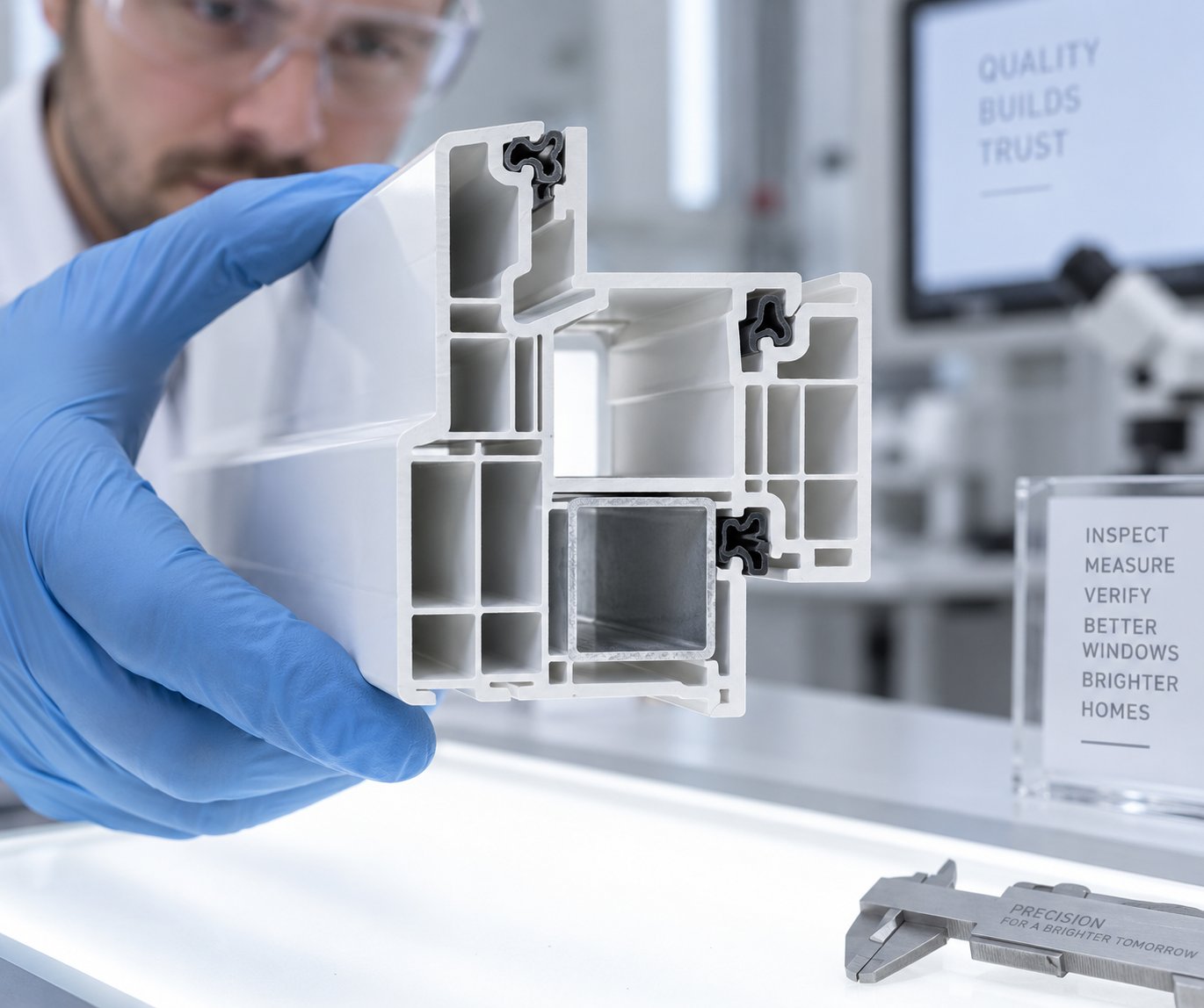
While surface flaws damage aesthetics, dimensional defects threaten functionality. A window frame profile with uneven wall thickness fails structural testing. A trunking section that warps after cutting won't snap together on a job site. These defects are often more insidious than surface issues because they can exist invisibly inside the profile — only revealed when a quality inspector measures a cross section or a customer reports field failures. For extruded PVC profiles to meet certification requirements, dimensional stability must be controlled from the die lip all the way through the stacking table.
| Defect | Symptoms | Root Causes | Corrective Actions |
|---|---|---|---|
| Uneven Wall Thickness | One side of the profile measures thicker than the opposite side, or individual chambers within a multi-chamber profile show inconsistent wall dimensions. Detected by cross-section measurement or ultrasonic gauging. | Die centering error causing asymmetric melt distribution; uneven melt flow from imbalanced die flow channels; inconsistent barrel-zone heating creating viscosity differences across the melt stream; worn or misaligned mandrel in hollow sections. | Re-center the die using adjustment bolts while monitoring wall thickness at the die exit. Inspect die flow channels for blockage or asymmetric buildup. Verify barrel heater function across all zones — a failed heater band on one side creates a cooler, more viscous melt path that flows slower. For persistent directional thickness errors, check die alignment relative to the calibrator entrance. |
| Warping and Bowing | Finished profile curves, twists, or bows along its length after cutting. May worsen over hours as residual stresses relax. Particularly visible in asymmetric profiles or those with varying wall sections. | Uneven cooling — one side of the profile solidifies faster than the other, locking in differential shrinkage stresses; calibrator misalignment pulling the profile off-center; asymmetric die flow creating internal orientation differences; haul-off belts applying uneven grip pressure; insufficient total cooling before cutting. | Check cooling water distribution in the calibration tank — blocked spray nozzles or uneven water levels create one-sided cooling. Verify calibrator alignment relative to the die centerline. If warping follows a consistent direction, inspect the die for flow imbalance on the corresponding side. Ensure the haul-off grips the profile symmetrically. For profiles that warp after cutting, extend cooling length or reduce line speed to ensure full through-wall solidification before the profile exits the cooling bath. |
| Sink Marks | Shallow depressions or inward-pulling surfaces on the profile's exterior, typically located opposite thick wall sections, ribs, or internal support webs. | Insufficient cooling causing the thick interior section to shrink as it solidifies after the outer skin has already hardened; excessive wall thickness in the die design creating thermal mass that cannot cool evenly; vacuum level too low in the calibrator to hold the surface against the sizing sleeve during shrinkage. | Increase cooling capacity — extend immersion length, lower water temperature, or increase spray volume opposite the affected area. Raise vacuum level in the calibrator to maintain surface contact during the shrinkage phase. If sink marks persist, review the die design — reducing rib or web thickness relative to the outer wall minimizes differential shrinkage. Slowing line speed also provides more cooling time per meter. |
| Profile Distortion at Cutting | Profile deforms, flattens, or shows clamp marks when the cutting saw engages. Cut face may appear angled or rough rather than square and clean. | Profile still retaining significant internal heat at the cutting station — the PVC is too soft to withstand clamp pressure or blade contact; excessive clamp pressure crushing a profile that hasn't fully solidified; dull blade generating heat and dragging rather than cutting cleanly; haul-off speed instability causing the profile to shift during the cut cycle. | Measure profile temperature before the cutter — if still warm, extend cooling or reduce line speed. Reduce clamp pressure to the minimum needed for stable cutting. Replace or sharpen the saw blade. Verify haul-off speed stability and encoder signal accuracy. Do not blame the cutter if the profile is already dimensionally unstable upstream — move the diagnosis backward to cooling or calibration first. |
A practical rule worth remembering: if the defect is already visible at the die exit, the problem lives upstream — in the melt, the barrel, or the die itself. If the product looks correct at the die but changes shape or dimension during sizing, cooling, or hauling, troubleshoot station by station moving downstream. Skipping this localization step is the single most common reason PVC extruded profiles keep failing after multiple "fixes" that never addressed the actual root cause.
When to Inspect Your Screw and Barrel for Wear
Some defects don't arrive suddenly. They creep in — so gradually that operators compensate without realizing it. Screw speed edges up a few RPM each month to maintain output. Melt temperature drifts slightly higher despite no change in barrel set points. Motor amperage climbs. The profiles still look acceptable, but margins are thinning because the line is working harder to produce the same result. This slow erosion of performance is the hallmark of progressive screw and barrel wear.
Here's what's physically happening. As the screw flights wear down and the barrel bore enlarges, the clearance between flight tip and barrel wall increases. Material leaks backward over the flights instead of being pushed forward efficiently — a phenomenon sometimes called "back leakage" or "pressure flow over the flights." The extruder loses pumping efficiency. To maintain the same output rate, screw speed must increase. Higher speed means more frictional shear heat, which raises discharge temperature — a dangerous escalation for thermally sensitive PVC. Plastics Technology illustrates this clearly: for a worn screw running at constant output, the required screw speed and discharge temperature both rise progressively with increasing flight clearance, eventually reaching a point where product quality can no longer be maintained at the original production rate.
What should trigger a wear inspection? Watch for this cluster of symptoms developing together over weeks or months:
- Declining specific output: Output (kg/h) divided by screw speed (RPM) drops — meaning each revolution of the screw delivers less material than it used to.
- Rising melt temperature at constant set points: Actual melt temperature measured at the barrel tip or die adapter gradually exceeds the programmed barrel zone temperatures, even though nothing has changed in the recipe or set points.
- Increasing motor amperage: The drive draws more current to maintain the same screw speed, reflecting higher resistance from inefficient melt conveying.
- Melt pressure instability: Pressure readings at the die adapter begin fluctuating more than they did when the screw was newer, producing visible dimensional variation in pvc extruded profiles.
- Higher defect rates: Surface quality deteriorates — more frequent shark skin, inconsistent gloss, or intermittent discoloration as stagnant material accumulates in the widening clearance zone.
When several of these indicators converge, it's time to pull the screw and measure. The standard assessment involves comparing the screw's outer flight diameter and the barrel's inner bore diameter against their original specifications. Industry guidelines suggest that flight clearance reaching roughly four times the original as-new clearance signals serious performance loss — though for critical-quality applications like medical or fenestration profiles, replacement may be warranted much sooner, at around two times the original clearance.
One detail that experienced maintenance teams never overlook: a screw should never be refurbished more than three times, because each hard-facing weld cycle degrades the base metal and increases the risk of delamination between the hard facing and the underlying screw body. And when the screw comes out for inspection, always measure the barrel bore as well. A bimetallic barrel liner typically outlasts three screw lifetimes, but confirming its condition during every screw change prevents the unpleasant surprise of installing a fresh screw into a worn barrel — and watching performance fail to recover.
Recognizing wear symptoms and understanding when to act is one thing. Having a structured maintenance strategy — with defined inspection intervals, clear replacement triggers, and access to precisely matched replacement components — is what transforms reactive crisis management into predictable, budgetable upkeep.
Maintenance Strategy and Wear Parts Replacement for PVC Profile Extruders
A structured maintenance plan turns scattered firefighting into budgetable, scheduled work — and that distinction alone can save a profile extruder operation thousands of hours in unplanned downtime over the life of a line. The previous section revealed how wear symptoms gradually erode output and quality. This section gives you the framework to catch those symptoms on a schedule, measure them objectively, and act before they cost you production.
Preventive Maintenance Schedules for Key Components
Every component on a pvc profile extrusion line wears at its own rate, driven by different mechanisms — abrasion, thermal cycling, mechanical fatigue, or chemical attack. Grouping inspections by frequency ensures nothing falls through the cracks while keeping planned downtime efficient. The table below consolidates inspection intervals, telltale wear indicators, and the triggers that should prompt replacement or rebuild rather than continued monitoring.
| Component | Inspection Frequency | Wear Indicators | Replacement / Action Triggers |
|---|---|---|---|
| Extruder Screw | Monthly trend measurement; physical pull and measure every 2,000–3,000 operating hours | Declining specific output (kg/h per RPM); rising melt temperature at constant set points; increasing motor amperage; visible flight-crest wear or pitting | Flight clearance reaches approximately 2x original as-new clearance for critical profiles, or 4x for general applications; visible cracking or delamination on hard-faced flights |
| Barrel Bore | Measure bore diameter during every screw pull; monthly melt pressure trending | Bore diameter growth beyond specification; inconsistent melt quality despite new screw; dark oil or iron particles in purge material | Bore diameter exceeds manufacturer's maximum tolerance; bimetallic lining worn through to base steel (visible as soft spots or accelerated localized wear) |
| Die Head | Weekly lip inspection during production; full disassembly and cleaning every 500–1,000 hours or at each product changeover | Persistent die lines that return after cleaning; flow channel discoloration indicating degraded PVC buildup; bolt torque loss from thermal cycling | Land surface pitting or corrosion too deep to polish out; flow channel erosion altering wall thickness distribution; cracked or warped die plates |
| Vacuum Pump | Daily vacuum level check; monthly performance test against baseline ultimate vacuum | Declining vacuum level at constant pump speed; increased pump noise; oil discoloration or emulsification; rising pump operating temperature | Ultimate vacuum falls below the level required to hold profile dimensions in the calibrator; vane wear exceeds rebuild tolerance; seal failure causing oil leakage into the water circuit |
| Haul-Off Belts | Weekly visual and tactile inspection; monthly encoder accuracy verification | Glazed or cracked belt surfaces; visible thinning or uneven wear patterns; profile surface marking or slipping at normal clamp pressure; speed feedback drift | Belt thickness below minimum for reliable grip; surface hardening preventing conformance to the profile shape; encoder deviation causing cut-length errors exceeding tolerance |
| Cutting Saw Blade | Daily visual check of cut quality; weekly blade edge inspection | Burrs or rough edges on cut face; angled cuts; increased cutting force or motor load; heat discoloration at the cut interface | Blade cannot produce clean, square cuts after resharpening; tooth loss or chipping; blade body warping from repeated heat cycles |
A practical tip from experienced maintenance teams: record every reading — even the "normal" ones. As extrusion maintenance specialists note, trend data is the difference between planned maintenance and emergency repair. A single melt pressure reading tells you the current state; repeated readings over weeks and months reveal the direction of wear. If melt pressure, gearbox temperature, or screw clearance moves in the wrong direction across two or three measurement intervals, schedule the repair before the line forces the schedule for you.
Screw and Barrel Wear Assessment
Knowing that wear exists is useful. Quantifying exactly how much wear has occurred — and where — is what separates a data-driven replacement decision from a guess.
For the barrel, the assessment involves measuring the internal bore diameter at multiple axial stations using a telescoping bore gauge or an inside micrometer. On a conical twin-screw profile extruder, this is especially important because the bore diameter changes along the taper. A measurement without its axial location is essentially useless — two technicians measuring at different points along the same barrel will record different values, and both may be perfectly accurate. Industry guidance recommends choosing one stable reference face — typically the gearbox-side barrel mounting face — and recording every measurement as a distance from that datum. Compare each station's current bore diameter against the original as-manufactured dimension to calculate radial wear.
For the screws, measure the outer flight diameter at the same axial stations. The critical metric is radial clearance at each point: (barrel bore inside diameter minus screw flight outside diameter) divided by two. Subtract the baseline as-new clearance to determine how much material has been lost. Converting this into a wear rate — millimeters of clearance growth per 1,000 running hours — gives you a predictive tool: you can project when the clearance will reach your replacement threshold and schedule accordingly, well before output or quality collapses.
Practical benchmarks from the field help frame these numbers. When flight wear reaches approximately 10% of the original flight depth, plasticizing performance begins to degrade rapidly. At that point, pvc profile extruders start demanding higher screw speeds and barrel temperatures to compensate, accelerating wear further in a self-reinforcing cycle. For mild wear under 0.2 mm of clearance growth, continued monitoring is appropriate. Moderate wear in the 0.3 mm to 0.5 mm range typically warrants scheduling a refurbishment. Severe wear beyond 0.5 mm — or any visible cracking, shaft distortion, or tip damage — calls for immediate replacement rather than attempting repair.
Selecting Replacement Screw Barrels for Consistent Quality
Here's where many manufacturers stumble: they identify the wear, authorize the replacement, and then source the cheapest available screw and barrel set — only to find that the "equivalent" components don't deliver the same plasticizing performance as the originals. The result is weeks of process instability, elevated scrap rates, and operators chasing settings that should have been dialed in from day one.
Why does this happen? Because a screw and barrel are not generic commodity parts. The taper angle, flight geometry, compression ratio, channel depth progression, surface treatment, and alloy composition all interact as a matched system. On a conical twin-screw pvc profile extruder, the relationship is even more tightly coupled — the two screws must mesh precisely within their tapered bores, and the clearances at every axial station must fall within tight tolerances for the self-wiping action and compression profile to function as designed. Installing a replacement set with even slightly different flight geometry or surface hardness can shift the plasticizing behavior enough to produce subtle but persistent quality issues: uneven fusion, inconsistent melt pressure, or accelerated re-wear.
The choice of surface treatment matters enormously for PVC applications. Nitrided screws and barrels offer a cost-effective solution for clean, lightly filled compounds, providing a hardened diffusion layer of typically 0.4 to 0.7 mm. However, for formulations containing higher calcium carbonate loading, recycled PVC regrind, or corrosive stabilizer by-products, bimetallic construction — with PTA hardfacing on the screw flights (1.0 to 1.5 mm) and centrifugally cast alloy lining in the barrel bore (2.0 to 3.0 mm) — provides significantly more wear material before the softer base steel becomes exposed. Industry data suggests bimetallic systems can last roughly two to three times longer than nitrided equivalents in abrasive or corrosive duty, at approximately 1.5 to 2 times the initial cost.
This is precisely where working with a specialist supplier pays for itself. NANHAIYA, for example, manufactures custom and replacement conical twin screw barrels specifically for PVC pipe, PVC profile, PVC board, foam board, and WPC extrusion applications. Their focus on stable plasticizing performance means each replacement set is engineered to match the original screw-barrel geometry — taper, flight profile, alloy selection, and surface treatment — so manufacturers can minimize downtime and return to consistent production without weeks of trial-and-error parameter adjustment. For PVC profile extrusion operations where every hour of unplanned downtime carries a real cost, that kind of precisely matched replacement support transforms a maintenance event from a production crisis into a routine, predictable procedure.
Screw and barrel condition, of course, is just one element of long-term line performance. The decisions made before machines are even ordered — factory layout, utility planning, and increasingly, sustainability and regulatory compliance — shape how efficiently and profitably that line operates for years to come.
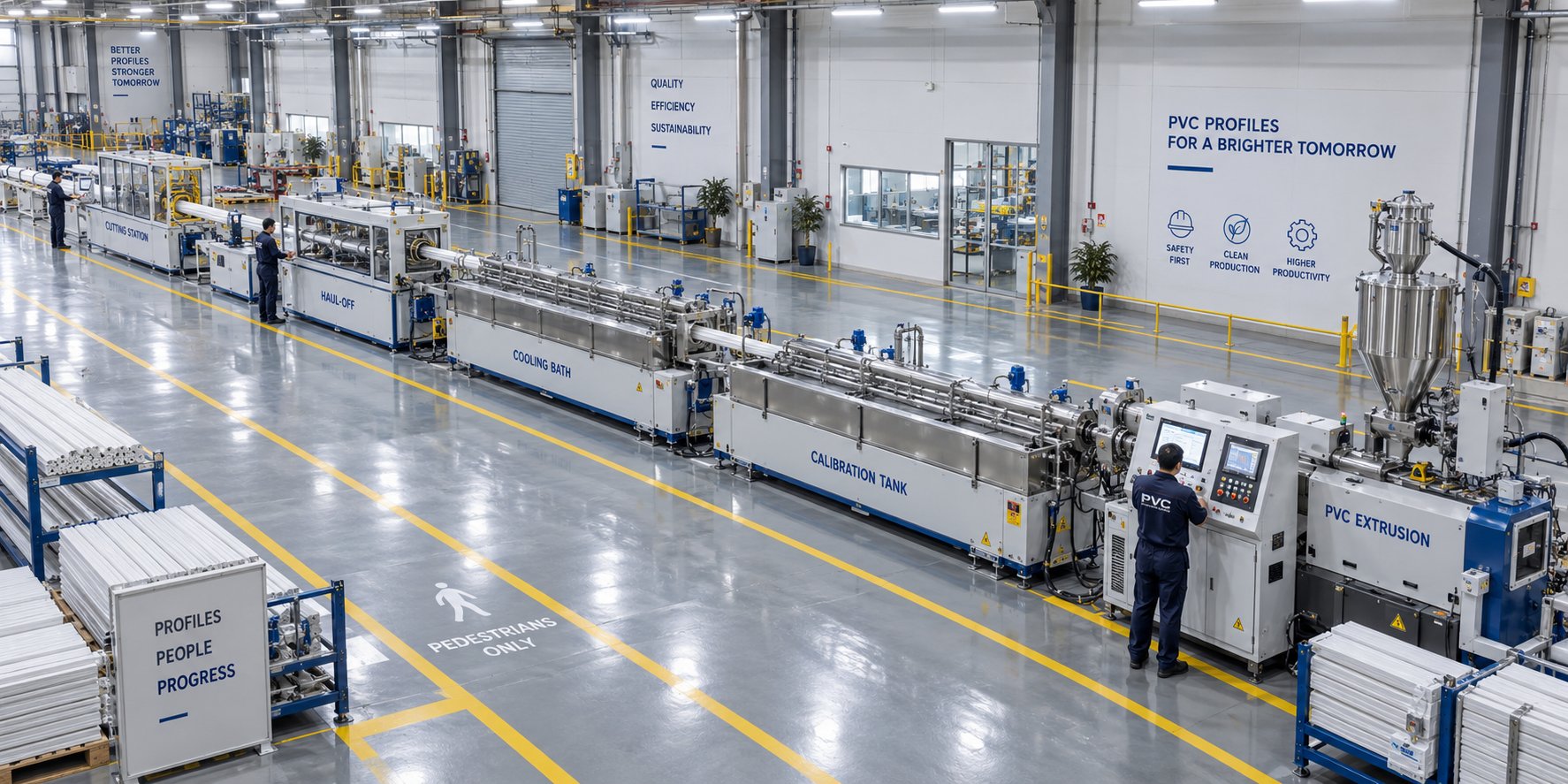
Factory Layout and Sustainability Planning for Your PVC Profile Extrusion Line
Screw geometry, barrel metallurgy, and maintenance schedules all live inside the machine. But the machine itself lives inside a factory — and the decisions you make about that factory before equipment ever arrives determine whether the line runs at its designed capacity or fights its surroundings from day one. Floor space, ceiling height, utility capacity, and even the direction material flows through the building are engineering decisions that deserve the same rigor as selecting an extruder architecture. Retrofitting a too-short building or upgrading an undersized electrical supply after installation is exponentially more expensive than getting the layout right on paper.
Factory Floor Layout and Line Length Estimation
How long is a pvc profile extrusion line? That depends almost entirely on the profile's complexity and the downstream equipment count. A simple decorative trim line — single-wall, small cross section, modest cooling requirements — might fit within 20 to 25 meters from extruder to stacking table. A multi-chamber window frame line with vacuum calibration, multiple cooling baths, haul-off, flying saw, and automated stacking can stretch to 35 meters or longer. Add co-extrusion for ASA cap layers, a pvc profile wrapping machine for foil lamination, or on-line punching stations, and you'll push past 40 meters easily.
But line length is only one dimension of the problem. You also need lateral clearance for operator access and maintenance — typically a minimum of 1.5 meters on each side of the line. Behind the extruder, allow space for screw pulls during maintenance; this means clearance equal to at least the full screw length behind the gearbox end. Upstream, the hot-cold mixer, storage silos, and pneumatic conveying equipment occupy their own footprint, often in an adjacent room or mezzanine level. Downstream, the stacking or tilting table feeds into a packaging and palletizing area that must accommodate forklift traffic and finished-goods staging.
As Jiahao Machinery's factory planning guide emphasizes, a workshop dimension copied from another installation is not a reliable specification for a new line. Share your actual site dimensions — including column locations, entrance widths, and usable ceiling height — with the equipment supplier early, so they can verify that the proposed configuration fits before building alterations begin.
Here are the major utility requirements you'll need to plan for and their roles in keeping the line running:
- Electrical supply: The extruder drive motor alone can draw 50 to 150 kW or more depending on screw size and output. Add barrel heaters, downstream motors, vacuum pumps, and controls, and total connected load for a complete line typically ranges from 100 to 300 kW. Confirm available voltage, frequency, and phase arrangement against the supplier's specification before committing to switchgear.
- Cooling water: Calibration tanks, cooling baths, barrel cooling jackets, and hydraulic oil coolers all require chilled or ambient water at specified flow rates, temperatures, and pressures. A typical profile line may consume 10 to 30 cubic meters per hour of recirculated cooling water. Water quality matters — untreated hard water fouls heat exchangers and blocks calibration spray nozzles.
- Compressed air: Pneumatic actuators on the cutting saw, air-operated clamps, and blow-off nozzles require clean, dry compressed air — commonly at 6 to 8 bar. Moisture or oil contamination in the air supply can mark profile surfaces or interfere with sensor readings.
- Ventilation and fume extraction: PVC processing can release trace amounts of hydrogen chloride and plasticizer fumes, particularly during start-up, purging, or if degradation occurs. Localized extraction at the die head and adequate general ventilation protect both operators and equipment.
- Material handling: Pneumatic conveying from silos to the extruder hopper, forklift access for raw material delivery and finished-goods removal, and safe storage areas for dry blend all need to be mapped into the layout from the start.
A joint readiness checklist covering access, utilities, installation responsibilities, and trial materials — agreed upon between the buyer and equipment supplier before the machines ship — prevents the painful discovery that a doorway is too narrow for the calibration tank or that the transformer capacity falls short of the connected load.
Sustainability and Regulatory Compliance Considerations
Vinyl extrusion has undergone a quiet but significant regulatory transformation over the past decade, and lines commissioned today must reflect current — not legacy — compliance realities. The most impactful shift has been the move away from lead-based stabilizers. Within the European Union, the voluntary phase-out of lead stabilizers in PVC was completed by 2015, and REACH regulations continue to tighten restrictions on substances of very high concern. Calcium-zinc and organic-based stabilizer systems have become the standard replacements, offering comparable thermal stability without the environmental and health liabilities of lead compounds. For manufacturers exporting to EU markets or multinational construction projects, lead-free formulation is no longer optional — it's a market access requirement.
PVC's recyclability is another sustainability factor that directly influences line specification. Rigid PVC profiles can be mechanically recycled multiple times without catastrophic property loss, and post-industrial regrind — edge trims, start-up scrap, and off-spec profiles — is routinely reincorporated into new production. Most manufacturers blend regrind at 5% to 15% of the total compound, depending on the application's quality requirements and the regrind's thermal history. Modern lines accommodate this through dedicated regrind dosing stations — often gravimetric feeders that meter recycled material into the main compound stream at a precisely controlled ratio. For operations also running a pvc rigid sheet extrusion line alongside profile production, regrind management becomes even more important because sheet trimming generates significant volumes of reusable material.
Industry frameworks like VinylPlus, the European PVC industry's voluntary sustainability commitment, have set targets for recycling volumes and responsible additive use, reinforcing the business case for lines designed with circularity in mind from the outset.
Quality Standards and Acceptance Testing for Finished Profiles
The profiles coming off your stacking table don't just need to look right — they need to pass a battery of standardized tests that buyers, building authorities, and certification bodies will specify. Understanding these requirements before commissioning a new line ensures that the equipment configuration, the compound formulation, and the process parameters are all aligned to produce profiles that meet specification from the first production run.
Dimensional tolerances are the starting point. Standards such as EN 12608 for window profiles define permissible variation in wall thickness, chamber dimensions, and overall cross-sectional geometry. Profiles that fall outside these tolerances may fit poorly during fabrication, compromise structural performance, or simply fail incoming inspection at the customer's facility. Tight tolerances demand the closed-loop wall-thickness monitoring, stable haul-off control, and consistent calibration discussed earlier in this article — every upstream process decision echoes in the final dimensional report.
Beyond dimensions, finished profiles face mechanical and weathering tests that verify long-term performance:
- Impact resistance: Charpy or falling-weight impact tests at low temperatures (-10°C or lower) confirm that the profile can withstand handling, transport, and installation forces without brittle fracture — a property heavily influenced by impact modifier dosage and fusion quality.
- Heat reversion: Profiles are exposed to elevated temperature, and any dimensional change is measured. Excessive reversion indicates locked-in orientation stresses from incorrect haul-off speed or insufficient cooling.
- Accelerated weathering: Xenon-arc or UV exposure testing simulates years of outdoor service, evaluating color stability, surface chalking, and mechanical property retention. This is especially critical for profiles used in fenestration and exterior cladding.
- Corner weld strength: For window and door profiles, welded corner samples are tested in tension to verify that the compound achieves sufficient fusion for reliable frame fabrication.
Specifying these tests — and confirming that your line, your formulation, and your process can consistently meet them — should happen during the equipment selection and compound development phase, not after the line is installed. Every element covered in this article feeds into that final outcome: the screw geometry that ensures complete fusion, the barrel temperature profile that protects stabilizer reserves, the calibration system that locks in dimensions, and the maintenance strategy that keeps all of it performing year after year. A pvc profile extrusion line is, ultimately, only as good as the weakest link in that chain — and the strongest operations are the ones that engineer every link with equal care.
Frequently Asked Questions About PVC Profile Extrusion Lines
1. What are the main components of a PVC profile extrusion line?
A complete PVC profile extrusion line includes a hot-cold mixer for dry blending, a twin-screw extruder for plasticizing, a die head for shaping, a vacuum calibration tank for dimensional sizing, cooling baths, a haul-off unit for speed-controlled pulling, a cutting saw, and a stacking table. Each unit must be precisely synchronized — a mismatch between extruder output and cooling capacity, for example, causes dimensional drift and surface defects. Lines may also include co-extrusion units, wrapping machines, or on-line punching stations depending on profile complexity.
2. Why is a conical twin-screw extruder preferred for PVC profile extrusion?
Conical twin-screw extruders dominate PVC profile production because their tapered geometry naturally suits PVC's processing challenges. The wide feed end accepts low-bulk-density PVC powder without bridging, while the gradual taper toward the discharge end builds compression slowly, generating less frictional shear heat than abrupt transitions. This is critical because PVC degrades within a very narrow thermal window. Additionally, the intermeshing screw design provides a self-wiping action that prevents stagnant melt pockets where PVC would overheat and char. Specialist manufacturers like NANHAIYA produce custom conical twin screw barrels engineered specifically for stable PVC plasticizing across profile, pipe, board, and WPC applications.
3. How do you troubleshoot shark skin and surface defects in PVC extrusion?
Shark skin in PVC extrusion appears as a dull, scaly, or rippled surface at the die exit. It typically results from melt temperature being too low for the compound's flow needs, excessive shear rate at the die land, or a die land length that is too short. Corrective steps include gradually raising melt or die zone temperatures, reducing screw RPM or line speed, and inspecting the die lip for buildup or damage. The key diagnostic rule is to check the profile at the die exit first — if the surface looks rough there, the root cause is upstream in the melt or die tooling, not in downstream cooling or calibration equipment.
4. When should you replace screws and barrels on a PVC profile extruder?
Watch for a cluster of symptoms developing over weeks or months: declining specific output per RPM, rising melt temperature despite unchanged barrel set points, increasing motor amperage, melt pressure instability, and higher defect rates. Physically measure screw flight diameter and barrel bore diameter at multiple axial stations and compare against original specifications. For critical fenestration or certification-grade profiles, replacement is typically warranted when radial clearance reaches about twice the as-new value. For general-purpose profiles, roughly four times the original clearance signals serious performance loss. Always measure the barrel bore when pulling a screw — installing a new screw into a worn barrel will not restore performance.
5. What factory utilities are needed to run a PVC profile extrusion line?
A PVC profile extrusion line requires several key utilities: electrical supply ranging from 100 to 300 kW total connected load depending on line size; recirculated cooling water at 10 to 30 cubic meters per hour for calibration tanks, cooling baths, and barrel jackets; clean, dry compressed air at 6 to 8 bar for pneumatic actuators and blow-off nozzles; and localized fume extraction at the die head area. Water quality is important — untreated hard water fouls heat exchangers and blocks calibration spray nozzles. Plan the full layout including line length (20 to 40+ meters), lateral access clearance, screw-pull space behind the extruder, and upstream mixing and storage areas before equipment arrives.
Written by
Nanhaiya Technical Team
Zhoushan Nanhaiya Plastic Machinery Co., Ltd.
The Nanhaiya technical team supports screw and barrel manufacturing projects through application review, technical communication, custom manufacturing coordination, and production and quality control.
Discuss Your Application
Related Articles
More insights on screw barrel technology and plastics processing.
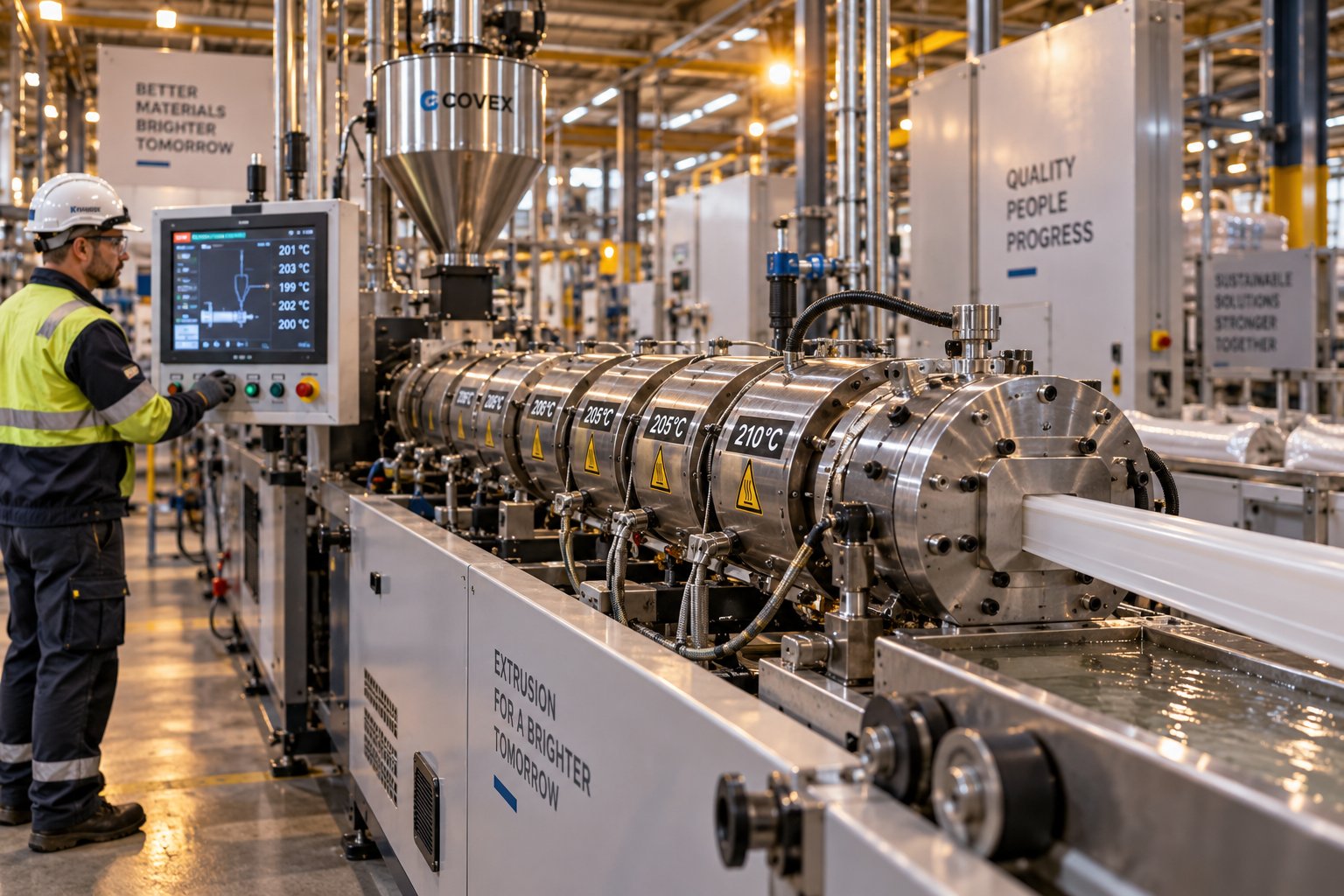
Plastic Extrusion Troubleshooting: Trace Every Defect to Its Source
Oct 16, 2026
Master plastic extrusion troubleshooting with this symptom-first guide. Diagnose defects zone by zone, fix root causes, and prevent recurring issues fast.
Read Article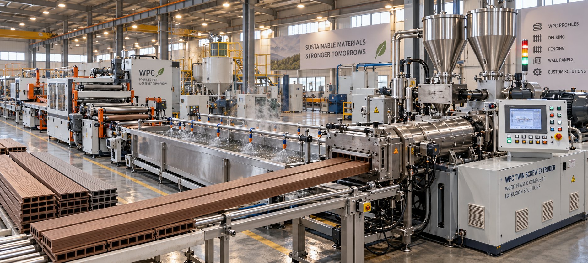
WPC Profile Extrusion Machine Decoded: Raw Blend To Flawless Profile
Oct 15, 2026
Learn how a WPC profile extrusion machine works — from extruder types and temperature zones to troubleshooting, wear management, and emerging co-extrusion trends.
Read Article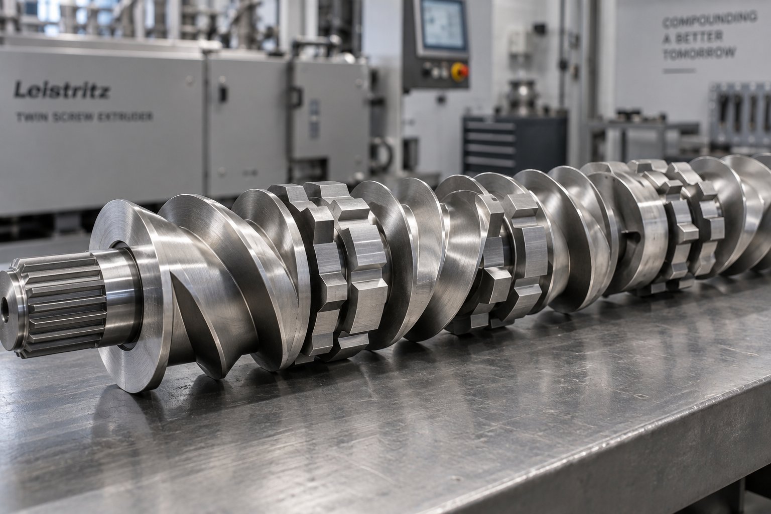
Twin Screw Extruder Screw Decoded: Geometry, Wear & Profile Fixes
Oct 14, 2026
Master twin screw extruder screw design: geometry parameters, kneading block stagger angles, element classification, wear mechanisms, and profile troubleshooting fixes.
Read ArticleLooking for something else?
Search by material, symptom or product and jump straight to the relevant page.
These are navigation suggestions based on keyword matching — not a quotation, not a delivery commitment, and not a substitute for engineering review. Final specification is confirmed by our engineers against your drawings and processed material.
Need help with screw barrel selection?
Share your machine model, processed material and application. Our team can help with pricing and technical support.