

What Twin Screw Extruder Screw Configuration Really Means
Imagine two identical twin screw extruders sitting side by side on the same production floor. Same barrel length. Same motor. Same temperature setpoints. Yet one consistently produces flawless pellets while the other churns out inconsistent, poorly mixed material. The difference? The arrangement of screw elements inside each barrel.
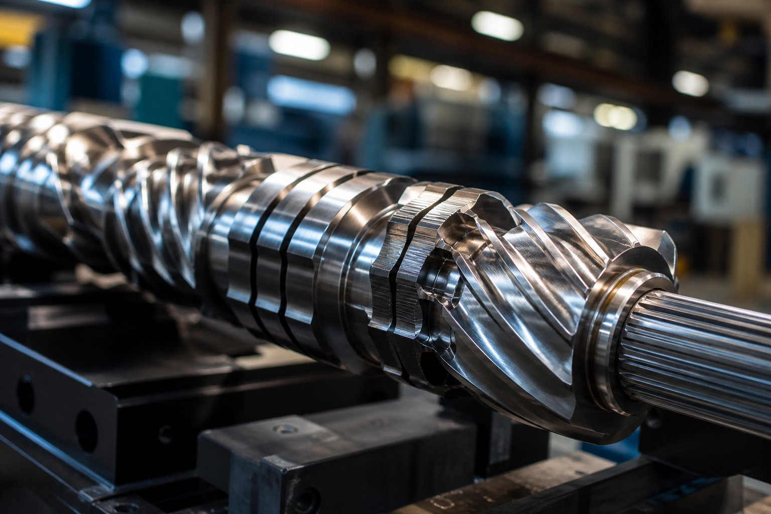
That arrangement is your twin screw extruder screw configuration — the deliberate sequencing of modular screw elements along a splined shaft to achieve specific processing objectives like melting, mixing, devolatilization, and pressure buildup. It is not simply the screw itself. It is the precise order, combination, and positioning of individual elements that dictates how your material transforms from raw feedstock into finished product.
Defining Screw Configuration in Twin Screw Extrusion
A screw profile consists of different screw elements configured together on the screw shaft, and the arrangement of these elements depends entirely on the process and material being run. As NC State Extension research emphasizes, no gold standard exists for designing a screw profile because every material exhibits unique flow properties — factors including temperature, shear rate, and extruder geometry all influence behavior. This makes twin screw extrusion both an engineering discipline and, frankly, a craft.
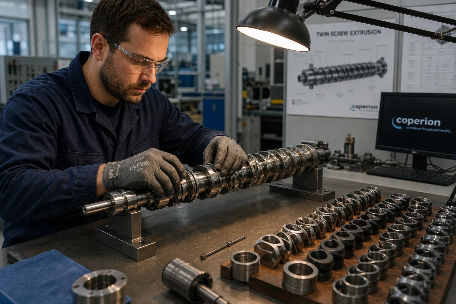
Think of screw elements as interchangeable building blocks. Conveying elements transport material forward. Kneading blocks break down agglomerates and melt polymers. Mixing elements homogenize your formulation. Reverse elements create backflow restriction. Each element type snaps onto the same splined shaft, yet swapping just a few blocks — or changing their order — can dramatically alter your output. The same extruder barrel can produce vastly different results depending on which elements you choose and where you place them.
Screw configuration determines residence time distribution, shear history, and energy input — the three pillars of product quality. Get these wrong, and no amount of temperature adjustment or speed optimization will save your process.
Why Element Sequencing Outweighs Machine Parameters
Most technical overviews start with the machine — barrel diameter, L/D ratio, motor power. Those specifications matter, of course. But here is the reality that experienced process engineers understand: barrel temperature and screw speed are secondary tuning variables. The element sequence is the primary design variable. It defines the shear environment your material encounters, how long it stays in each processing zone, and how much mechanical energy it absorbs.
A twin screw extruder with an aggressive kneading section will generate high shear regardless of whether you dial the RPM down by 20%. A configuration with insufficient mixing elements will produce poor dispersion no matter how high you push the temperature. Configuration shapes the boundaries of your process window — machine parameters simply let you operate within those boundaries.
This article takes a configuration-first approach. Rather than walking through extruder hardware specifications, you will find a detailed breakdown of every major element type, the science behind stagger angles and mixing mechanics, and a systematic methodology for building screw profiles from scratch. The goal is to give you the technical depth that sits between oversimplified manufacturer brochures and paywalled academic papers.
The foundation of that depth starts with understanding exactly what each element type does — and how its geometry drives material flow.
Complete Screw Element Taxonomy Every Engineer Needs
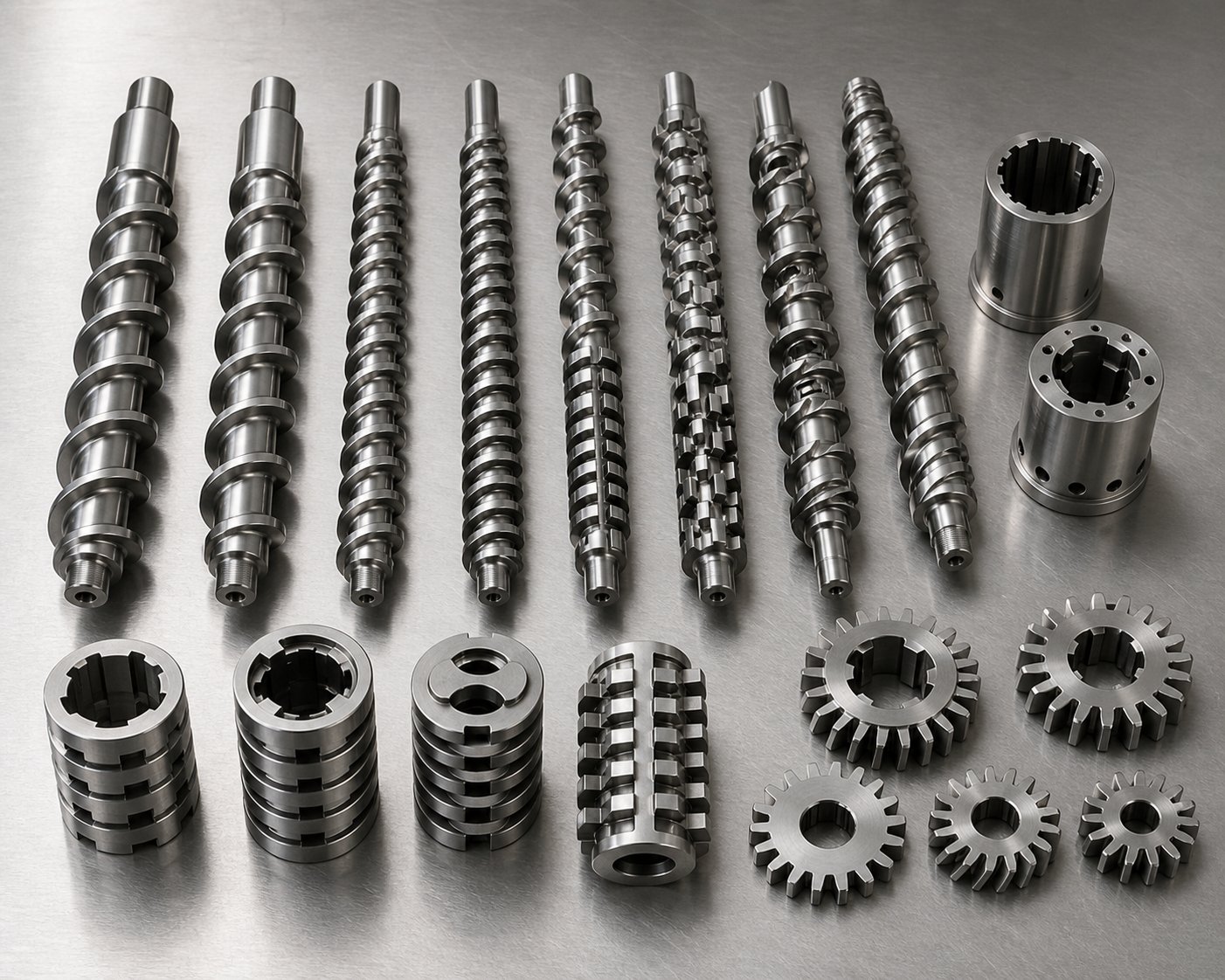
Every extruder screw built for a co-rotating twin screw system is assembled from a relatively small family of element types. Yet the differences between those types — in geometry, flow behavior, and processing impact — are enormous. Selecting the wrong element for a given zone is one of the fastest ways to undermine product quality, and the decision starts with knowing what each element actually does inside the barrel.
The table below provides a consolidated reference covering all major element categories, their geometries, functions, and where they typically sit along the screw profile. Use it as a quick-reference guide, then read the detailed breakdowns that follow.
| Element Type | Geometry Description | Primary Function | Typical Zone Placement |
|---|---|---|---|
| Large-Pitch Conveying | Deep-channeled helical flights with wide lead (e.g., 1.5D-2D pitch) | High-volume solids intake, fast forward transport | Feed zone, side feeder intake |
| Standard-Pitch Conveying | Moderate-depth helical flights (1D pitch) | General melt conveying, moderate pressure buildup | Melt conveying zone, transitions |
| Small-Pitch Conveying | Shallow-channeled flights with tight lead (0.5D-0.75D pitch) | Pressure generation, increased fill level | Pressure buildup zone before die |
| Reverse Conveying | Left-hand helical flights opposing forward flow | Backflow restriction, melt seal creation | Before devolatilization ports, zone boundaries |
| Narrow Kneading Block (Forward) | Thin elliptical discs staggered at 30-60 degrees in forward direction | Dispersive mixing with high material renewal rate | Melting zone, intensive mixing zone |
| Wide Kneading Block (Forward) | Thick elliptical discs staggered at 30-60 degrees in forward direction | High shear melting, strong dispersive mixing | Primary melting section |
| Neutral Kneading Block (90 degrees) | Discs offset at 90 degrees, eliminating forward pumping | Maximum shear and residence time, strong restriction | Intensive mixing or melt seal position |
| Reverse Kneading Block | Discs staggered in reverse (left-hand) direction | Backward pressure, combined mixing and sealing | Before vacuum vents, zone seals |
| Tooth Mixing Element (TME) | Grooved cylindrical elements with alternating teeth and channels | Distributive mixing through repeated splitting and recombining | Downstream mixing zone |
| Screw Mixing Element (SME) | Conveying-type flights with slots or grooves cut into the flight land | Combined conveying and distributive mixing | Gentle mixing zone, fiber-sensitive sections |
| ZME (Zahnmischelement) | Gear-like cam profiles with interlocking teeth | Elongational flow and distributive mixing at low shear | Color dispersion zone, heat-sensitive mixing |
Conveying Elements and Pitch Variations
Conveying elements are the workhorses of any extrusion screw. Their helical flights generate forward drag flow — material is pulled along the screw channel by the rotating flight surfaces pushing against the barrel wall. You will find them in every zone of the screw profile, but the pitch you choose changes their behavior dramatically.
Large-pitch (high-lead) conveying elements move material quickly with minimal shear and low fill levels. That makes them ideal for the feed zone, where you need to pull in raw pellets or powder without creating a bottleneck. They also work well beneath side feeder openings, where deep channels and high free volume prevent backflow of downstream material into the feeder throat.
As pitch decreases, the channel becomes shallower, fill level rises, and the element begins generating real pressure. Small-pitch (low-lead) elements near the die end of the twin screw and barrel assembly are responsible for building the pressure needed to push melt through the die. This transition from large to small pitch along the screw length mirrors the material's transformation from loose solid to pressurized melt.
Reverse conveying elements flip the helix direction entirely. Instead of pushing material forward, they create controlled backflow. The result is a localized melt seal — a fully filled section of barrel that prevents gases or volatiles from escaping upstream. You will see reverse elements positioned just before vacuum vent ports to isolate the devolatilization zone.
Kneading Blocks and Their Orientations
If conveying elements handle transport, kneading blocks handle transformation. Each kneading block consists of a series of elliptical discs mounted on the shaft at progressive angular offsets — this offset is the stagger angle, and it determines everything from shear intensity to forward pumping capability.
Forward-staggered kneading blocks (right-hand orientation) combine shear with some degree of conveying action, making them the default choice for melting and dispersive mixing zones. The disc width also matters significantly. Narrow discs provide a higher material renewal rate and stronger dispersion because more disc-to-disc transitions occur within a given length. Wide discs, by contrast, generate higher localized shear but exchange material between discs less frequently.
Neutral kneading blocks — those with a 90-degree stagger — deserve special attention in any screw blade configuration. Because the discs are perpendicular, there is zero net forward pumping. Material essentially stalls, experiencing intense shear and extended residence time. This makes 90-degree blocks powerful restrictive elements, but overuse risks thermal degradation in heat-sensitive polymers.
Reverse kneading blocks push material backward while simultaneously mixing it. They create moderate melt seals with an added benefit: the mixing action that a simple reverse conveying element cannot provide. Engineers often use them to seal devolatilization zones when some additional homogenization is needed at that boundary.
Specialized Mixing Elements — TME, SME, and ZME
Kneading blocks excel at dispersive mixing — breaking apart agglomerates, droplets, or solid particles through high shear stress. But many formulations also demand distributive mixing, where the goal is to spread already-small domains evenly throughout the melt without applying excessive force. That is where specialized elements enter the screw design.
Tooth mixing elements (TME) feature alternating rows of teeth and grooves that repeatedly split and recombine the melt stream. Imagine a flow of material being divided into thin layers, stacked, and divided again — this action creates excellent spatial uniformity with relatively low shear. TMEs are particularly effective for color masterbatch dispersion and additive distribution.
Screw mixing elements (SME) look similar to standard conveying elements at first glance, but their flight lands have slots or grooves cut into them. These openings allow some material to bypass the main channel, creating cross-channel flow while still maintaining forward conveying. The result is gentle distributive mixing without a significant pressure drop — a useful combination when you need mixing action in a transport-dominated section.
ZME elements (Zahnmischelement, or gear mixing elements) use interlocking cam or gear-like profiles to generate elongational flow rather than simple shear flow. As material passes through the meshing gear teeth, it stretches and folds rather than being ground between surfaces. This elongational mechanism is highly efficient for distributive mixing of engineering plastics and sensitive formulations where shear-induced degradation is a concern.
Each of these specialized elements addresses a different mixing challenge, and their placement within the overall configuration matters as much as their selection. However, choosing the right element is only half the equation — the angular relationships between kneading disc lobes introduce another critical layer of control over your process.
Kneading Block Stagger Angles and Their Impact on Mixing
You have identified the right element type for each zone. You know kneading blocks handle the heavy lifting of melting and dispersive mixing. But here is the question that separates a functional screw profile from an optimized one: what stagger angle should those kneading discs have?
The stagger angle is the angular offset between adjacent kneading disc lobes on a single kneading block. Picture looking at the end of a kneading block head-on. Each successive disc is rotated by a fixed number of degrees relative to the one before it. That rotation — whether it is 30, 45, 60, or 90 degrees — fundamentally changes how your material is sheared, conveyed, and retained within the block. It is one of the most powerful yet frequently misunderstood levers in twin screw extruder screw configuration.
How Stagger Angle Controls Shear and Conveying
Every forward-staggered kneading block creates a helical-like progression of disc lobes. As the twin screws rotate, material caught between lobes is dragged forward by that progression. The tighter the angular offset between discs, the more the block mimics the pumping behavior of a conveying element. As the offset widens, forward pumping weakens and shear intensifies — because material spends more time being worked between disc tips and the barrel wall instead of being pushed downstream.
Here is how each common stagger angle performs in practice:
- 30-degree stagger: This is the gentlest forward kneading configuration. The small offset between discs creates a strong forward pumping effect, moving material downstream almost like a conveying element but with added mixing action. Shear intensity is moderate. As Plastics Technology explains, a 30-degree kneading block has minimal mixing but conveys material forward the best. That makes it ideal for the beginning of a melting section, where you want to ease solid particles into the shear zone without causing backflow or feed instability.
- 45-degree stagger: A step up in intensity. The 45-degree offset delivers noticeably higher shear while still maintaining good forward pumping. This balance makes it one of the most commonly used stagger angles for co rotating twin screw extruder applications where moderate melting and mixing need to happen simultaneously. Many engineers treat it as the default starting point for initial melting zones.
- 60-degree stagger: At this angle, forward conveying drops significantly. The wider offset forces more material over the disc tips rather than along the inter-disc channels, generating high shear rates and strong dispersive mixing action. A 60-degree kneading block is much more efficient at mixing and imparts more energy to the material, though its poor forward-conveying capability means it must be supported by upstream elements that maintain material flow. It excels in demanding dispersive mixing tasks — breaking pigment agglomerates, dispersing nanofillers, or creating fine morphologies in polymer blends.
- 90-degree stagger (neutral): This is the extreme case. With discs perpendicular to one another, there is zero net forward pumping. Material oscillates back and forth across the block, experiencing maximum shear intensity and the longest local residence time of any forward-stagger configuration. Neutral kneading blocks function as strong restrictive elements, acting like a melt dam that forces the upstream section to fill completely. They are frequently placed at the end of a melting section in a parallel twin screw extruder to guarantee complete melting before material enters downstream zones.
Reverse-staggered kneading blocks take restriction even further. Their disc lobes progress in the opposite rotational direction, actively pushing material backward. This creates intense backpressure and a strong melt seal — essential for isolating devolatilization zones under vacuum. Because material is being pushed upstream against the overall screw extrusion flow, residence time spikes and shear forces are at their highest. For crystalline polymers requiring aggressive energy input to achieve full melting, reverse kneading blocks provide that extra push.
The following table summarizes how each stagger angle affects the key processing variables:
| Stagger Angle | Forward Conveying Effect | Shear Intensity | Residence Time Impact | Best Application |
|---|---|---|---|---|
| 30 degrees | Strong — close to conveying element behavior | Low to moderate | Minimal increase | Gentle initial melting, feed transition |
| 45 degrees | Moderate — reliable forward pumping | Moderate | Slight increase | General-purpose melting and mixing |
| 60 degrees | Weak — most material flows over disc tips | High | Noticeable increase | Intensive dispersive mixing, pigment dispersion |
| 90 degrees (neutral) | None — zero net forward pumping | Very high | Significant increase | Melt seal, complete melting restriction, maximum shear |
| Reverse (any angle) | Negative — pushes material backward | Very high | Substantial increase | Pressure seal for devolatilization, high-energy melting |
Notice the pattern: as stagger angle increases, forward conveying decreases and shear intensity rises. This is not a coincidence — it is a direct geometric consequence. The wider the angular step between discs, the less the block resembles a helical screw flight and the more it behaves like a series of stationary paddles working against the material.
Dispersive vs. Distributive Mixing Element Selection
Stagger angle selection connects directly to one of the most critical decisions in any screw design project: choosing between dispersive and distributive mixing.
Dispersive mixing breaks things apart. It relies on high shear stress and pressure gradients to fracture agglomerates, reduce droplet sizes in immiscible blends, and force incompatible phases into finer morphologies. Kneading blocks — especially those with steep stagger angles (60 degrees and 90 degrees) and narrow disc widths — are the primary tools for dispersive mixing. The intense shear generated between disc tips and the barrel wall, combined with the pressure fluctuations at each disc transition, creates the stress peaks needed to overcome cohesive forces within particle clusters.
Distributive mixing, by contrast, spreads things out. It repeatedly splits, stretches, and recombines the melt to ensure spatial uniformity without necessarily applying extreme force. Low-stagger kneading blocks (30 degrees) contribute some distributive mixing, but the real workhorses for this mode are specialized elements like TME, SME, and ZME gear elements. These elements divide melt flow into thin streams and reassemble them through geometric channels rather than brute-force shear.
Why does this distinction matter for your configuration? Because many real-world formulations require both mixing modes — and applying the wrong one at the wrong location creates problems. Using aggressive 60-degree or 90-degree kneading blocks where you only need uniform distribution wastes energy, raises melt temperature, and risks degrading heat-sensitive additives. Relying solely on gentle distributive elements when hard pigment agglomerates need breaking will leave you with visible specks and poor mechanical properties.
The practical approach is to sequence dispersive elements where agglomerate breakup is the priority — typically early in the mixing zone where viscosity is highest and stress transmission is most effective — then follow with distributive elements to homogenize the already-dispersed components. This layered strategy matches the twin screws' natural progression from high-viscosity initial mixing to lower-viscosity downstream blending.
Disc thickness adds another dimension to this selection process. Thicker kneading discs generate more shear because more material is forced over each disc tip. Thinner discs create more frequent disc transitions within the same block length, increasing the number of splitting and recombining events — favoring distributive action. So even within a single stagger angle, you can tune the balance between dispersive and distributive performance by adjusting disc width.
Stagger angle and element type together define the shear and mixing landscape of your screw profile. But they operate within physical constraints that are less visible yet equally important — constraints like free volume, the OD/ID ratio of your screw elements, and the precise clearances that keep those twin screws meshing without collision.
Free Volume and OD-ID Ratio as Hidden Design Parameters
Element types and stagger angles get most of the attention when engineers discuss screw profiles. But underneath those choices sit two fundamental geometric parameters that quietly govern how much material your twin-screw extruder can handle, how intensely it shears that material, and whether your devolatilization zones actually work. These parameters — free volume and OD/ID ratio — are baked into the screw geometry itself, and overlooking them is one of the most common reasons a well-planned configuration still underperforms.
Free Volume and Its Role in Devolatilization
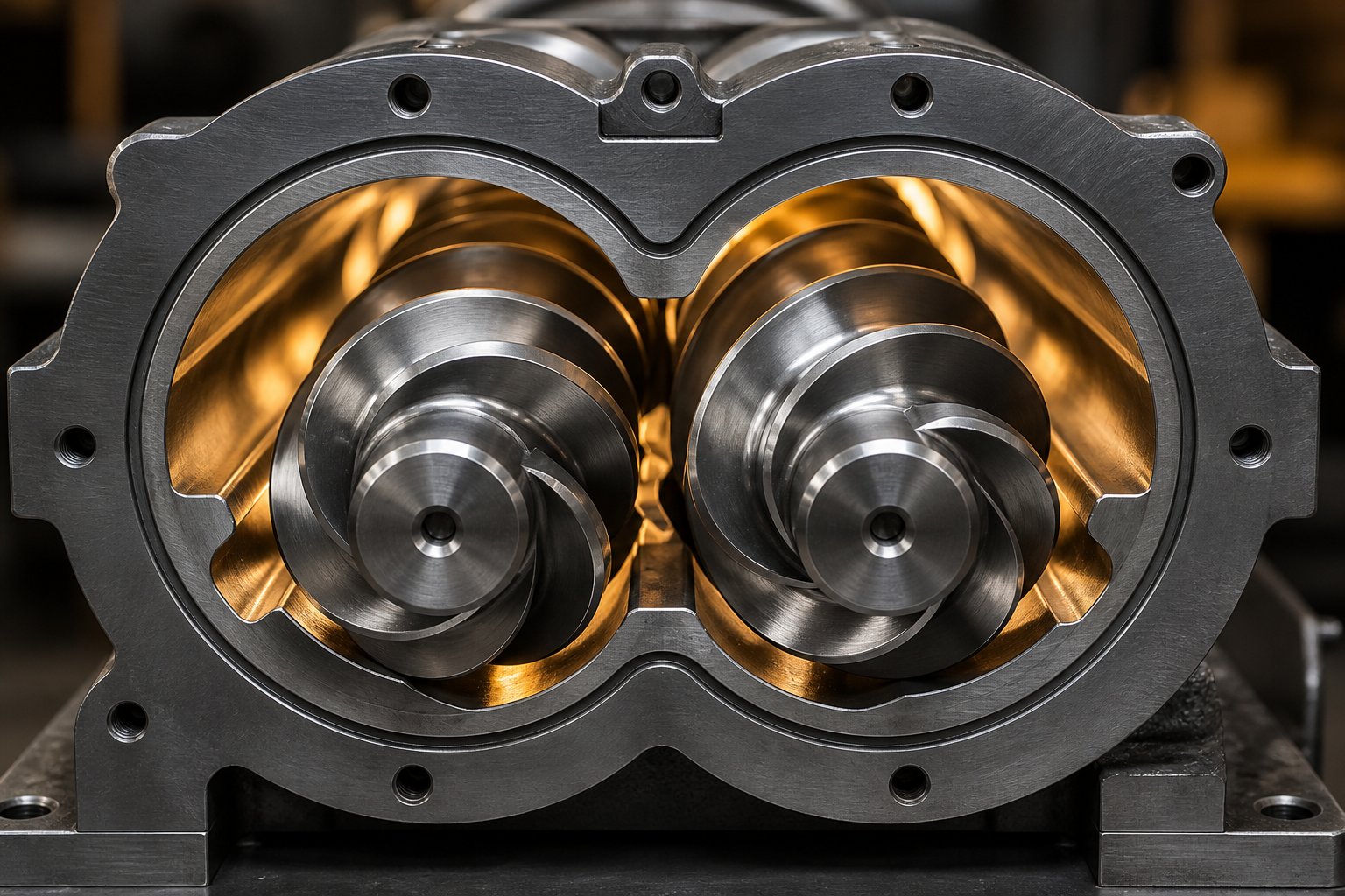
Free volume is the open cross-sectional area within the screw channel that is available for material to occupy. Picture looking at a cross-section of the barrel with both screws inside it. The space not filled by the screw flights, shaft, or barrel wall is your free volume. Different element geometries create different free volumes — a deep-channeled large-pitch conveying element offers significantly more open area than a tight-pitch element or a kneading block.
Why does this matter so much? Because free volume directly controls three things:
- Conveying capacity: Higher free volume means more room for incoming material, which directly limits your maximum feed rate before flood feeding occurs.
- Fill level: In starve-fed twin screw extruders — which is how most co-rotating machines operate — channels are only partially filled in conveying zones. The ratio of actual material volume to available free volume determines the degree of fill, which influences pressure profiles and mixing behavior throughout the barrel.
- Devolatilization efficiency: This is where free volume becomes critical. Effective volatile removal requires thin melt films with high surface area exposed to low-pressure or vacuum conditions. Partially filled channels with high free volume create exactly that environment — rolling melt pools with constantly renewed surfaces. If your devolatilization zone uses elements with low free volume, the channels fill up, melt pools deepen, and surface renewal drops. Volatiles get trapped inside thick melt layers instead of escaping to the vent port.
As Leistritz notes in their analysis of devolatilization efficiency, renewed surfaces come from rolling pools and partially filled screw channels — and increasing screw RPM while decreasing feed rate further improves those conditions. The geometric foundation enabling all of this is free volume. Without sufficient open channel area, no amount of vacuum or screw speed adjustment will compensate.
For context, free volume is typically expressed as cc per diameter (cc/dia) to normalize across different extruder twin screw sizes. A machine with 300 cc/dia free volume offers roughly 30% more volumetric capacity than one with 240 cc/dia at comparable screw diameters — a difference that translates directly into higher attainable throughput for volume-limited processes.
OD/ID Ratio Effects on Shear and Throughput
If free volume tells you how much space is available, the OD/ID ratio tells you how that space is shaped — and shaping determines shear.
The OD/ID ratio is the outer diameter of the screw element divided by its inner diameter (the root or shaft diameter). A higher ratio means the screw flights extend further from the shaft, creating shallower channels. A lower ratio means flights are shorter relative to the shaft, producing deeper channels.
This single ratio creates a fundamental trade-off that affects every processing decision:
- Higher OD/ID ratio (e.g., 1.55-1.66): Shallower channels generate higher shear rates because material is forced through a thinner gap between flight tip and barrel wall. Mixing intensity increases. However, the reduced channel depth means less volumetric capacity per revolution — so throughput potential drops for a given screw diameter and RPM. These ratios are standard in high-performance compounding where mixing quality takes priority over raw output.
- Moderate OD/ID ratio (e.g., 1.40-1.55): A balanced middle ground offering reasonable shear intensity alongside adequate throughput. Many general-purpose double screw extruder platforms use ratios in this range, making them versatile across a broad range of polymer formulations without extreme shear or extreme volume.
- Lower OD/ID ratio (e.g., 1.20-1.40): Deep channels maximize volumetric capacity and free volume but deliver substantially lower shear. These configurations suit applications where high throughput of easily processed materials is the goal, or where early-stage R&D requires micro-batch sampling with minimal material quantities. A 1.2/1 OD/ID ratio with just 1 cc/dia free volume, for example, enables processing of batches as small as 50 grams for scale-up evaluation.
There is an important nuance here that trips up many engineers. A higher OD/ID ratio does not always mean higher melt temperature. In fact, Leistritz technical data indicates that a higher OD/ID ratio can result in lower average shear per unit of material because the increased flight tip speed is distributed across a thinner melt layer. The relationship between OD/ID ratio and actual thermal-mechanical history depends on fill level, screw speed, and the specific element types involved — which is why this parameter must be evaluated in the context of your complete configuration, not in isolation.
Geometrical Constraints and Collision-Free Meshing
Co-rotating intermeshing twin screw extruders rely on a self-wiping geometry — each screw continuously scrapes material off the other screw's surface and off the barrel wall. This self-wiping action, based on the Erdmenger profile geometry patented in the 1950s, prevents material stagnation and thermal degradation. But it only works if the screws mesh without physically colliding.
Three types of clearance govern collision-free operation:
- Screw-to-screw clearance: The gap between the flight tip of one screw and the root of the other. This gap must be tight enough to maintain self-wiping but wide enough to prevent metal-to-metal contact as screws flex under torque and thermal expansion. A small amount of material — called leakage flow — passes through this clearance, and the amount of leakage directly affects mixing behavior. Tighter clearances reduce leakage and improve self-wiping but accelerate wear.
- Screw-to-barrel clearance: The radial gap between flight tips and the barrel bore. This clearance creates the overflight region, which is one of the most shear-intensive zones in the entire extruder. Material squeezed through this thin gap undergoes significant planar shear. A conical twin screw extruder has varying clearances along its tapered barrel, adding another layer of geometric complexity to clearance management.
- Inter-element transition tolerances: Where one screw element ends and another begins, the angular alignment must ensure smooth meshing with the corresponding element on the adjacent screw. Misalignment at element transitions can create localized pressure spikes, uneven wear, and disrupted flow patterns.
These clearances are not just manufacturing tolerances — they are active processing parameters. Leakage flow through screw-to-screw gaps contributes to backflow mixing. Overflight flow through screw-to-barrel gaps generates some of the highest shear stress the material experiences. And the balance between self-wiping effectiveness and component wear life defines the long-term reliability of your double screw extruder configuration.
Understanding free volume, OD/ID ratio, and meshing clearances gives you the geometric foundation beneath every element selection decision. These hidden parameters set the physical boundaries of what your screw profile can achieve — boundaries that become especially important when you begin sequencing elements zone by zone to build a complete configuration from scratch.
Step-by-Step Methodology for Designing Screw Configurations
Knowing your element types, stagger angles, and geometric parameters is essential — but how do you actually assemble all of those pieces into a working screw profile? Most technical resources stop short of answering that question. They catalog individual elements without explaining the logic of sequencing them together. The result is that many engineers end up copying existing profiles or relying on trial-and-error swaps rather than designing from first principles.
The twin screw extrusion process follows a predictable material transformation sequence: solid feedstock enters, gets melted, mixed, transported, stripped of volatiles, and pressurized for die exit. A well-designed screw configuration mirrors that sequence zone by zone, with each section's elements matched to the specific processing task at hand. Here is how to build one from scratch.
Zone-by-Zone Configuration Framework
Think of your screw extruder as a series of functional stations, each with a distinct job. The elements you place in each station — and how aggressively you configure them — depend on what your material needs at that exact point in its journey through the barrel. The following framework walks through each zone in order, from feed throat to die face.
- Zone 1 — Feeding: Start with large-pitch conveying elements (typically 1.5D to 2D pitch) directly under the feed throat. The goal here is simple: pull material in as fast and as smoothly as possible. Deep channels and high free volume prevent the feed port from choking, which is especially important for low-bulk-density powders or irregular pellet blends. As a general rule, large-pitch elements in the feeding section prioritize material throughput, reduce residence time, and minimize degradation risk. Avoid placing any restrictive elements within the first few diameters of the feed opening — even moderate fill buildup here causes feed instability and erratic torque spikes.
- Zone 2 — Melting and Plasticating: This is where your twin screw extruder machine begins transforming solid particles into a cohesive melt. Transition gradually from conveying elements into kneading blocks. Start with gentle stagger angles — 30-degree or 45-degree forward kneading blocks — to initiate softening and partial melting through moderate shear and friction. As the material progresses and its viscosity begins dropping, increase the stagger angle to 60 degrees or even 90 degrees to deliver the higher energy input needed for complete melting. This progressive ramp-up avoids the common mistake of hitting cold, rigid material with maximum shear immediately, which causes torque overload and uneven melt quality. For semi-crystalline polymers with high melting points, you may need a longer melting zone with additional kneading blocks. For amorphous resins, a shorter zone with moderate stagger angles often suffices.
- Zone 3 — Mixing: With the polymer fully melted, this zone is dedicated to blending in additives, fillers, pigments, or secondary polymers. The element selection here depends entirely on the type of mixing your formulation demands. For dispersive mixing — breaking apart agglomerates, reducing filler particle clusters, or creating fine blend morphologies — use kneading blocks with 60-degree stagger angles and narrow disc widths. For distributive mixing — spreading already-fine particles uniformly throughout the melt — switch to TME, SME, or ZME gear mixing elements that split and recombine flow streams without excessive shear. Many real-world formulations require both, so you will often see a dispersive kneading section followed immediately by a distributive mixing section within this zone.
- Zone 4 — Melt Conveying: Between mixing and devolatilization, you need a transport section that moves homogeneous melt downstream without adding unnecessary shear or energy. Standard-pitch conveying elements (approximately 1D pitch) handle this job reliably. This zone serves as a thermal buffer — giving the melt time to stabilize in temperature before entering the devolatilization section. Keep it simple. Over-engineering this section with mixing elements adds heat you do not want and complicates your process window for no real benefit.
- Zone 5 — Devolatilization: Effective volatile removal is one of the most configuration-sensitive operations in a double screw extruder machine. The zone directly beneath each vacuum vent port must use large-pitch conveying elements that keep the channel partially filled, exposing thin melt films with high surface area to low-pressure conditions. But the critical detail most engineers overlook is what comes immediately before the vent port: you need a melt seal. Place reverse conveying elements, reverse kneading blocks, or 90-degree neutral kneading blocks upstream of the vent to create a fully filled, pressurized barrier. This seal prevents vacuum from pulling air backward through the extruder and ensures that low pressure exists only where you need it — directly at the vent. Without this seal, volatiles lose their escape path and vent flooding or resin blow-up becomes likely.
- Zone 6 — Pressure Buildup and Pumping: The final section of your screw profile must generate enough pressure to push melt through the die at a consistent rate. Use tight-pitch conveying elements (0.5D to 0.75D pitch) that progressively decrease in lead toward the discharge end. These shallow-channel elements compress the melt, increase fill level to 100%, and build the die pressure needed for stable extrusion. The length of this section depends on the die's flow resistance — higher-restriction dies need longer pumping zones. Keep in mind that pressure generation always creates temperature rise, so minimize this zone's length to what your die actually requires.
Sequencing Rules for Element Transitions
Building each zone correctly is only part of the challenge. How you transition between zones determines whether your twin-screw extruder machine runs smoothly or fights itself at every boundary.
The most important sequencing rule is to avoid abrupt transitions in element aggressiveness. Jumping from a large-pitch conveying element directly into a 90-degree kneading block creates a sudden pressure spike and localized overheating. Instead, step through intermediate elements — a standard-pitch conveying element, then a 30-degree kneading block, then a 60-degree block. This graduated approach lets the material adjust progressively to increasing shear, reducing the risk of thermal degradation and mechanical surges.
A second principle involves fill continuity. Every restrictive element — whether a reverse conveying element, reverse kneading block, or neutral kneading block — creates a fully filled region that extends upstream. Make sure that the elements immediately upstream have enough conveying capacity to feed material into that restriction without starving or overpressurizing the zone. If your restriction is too aggressive relative to the upstream conveying pitch, you will see torque instability and inconsistent output.
Third, always place conveying elements downstream of every mixing section. Material leaving a kneading block zone is pressurized and shear-heated. Conveying elements relieve that pressure, restore partially filled flow conditions, and set up the next processing zone correctly. Stacking kneading sections back-to-back without intervening conveying elements creates excessively long fully filled regions with uncontrollable temperature rise.
Finally, match zone lengths to your material's actual requirements rather than defaulting to fixed proportions. A highly filled compound with 60% calcium carbonate needs a much longer mixing zone than a neat polymer blend. A hygroscopic material may need two separate devolatilization sections with independent vacuum ports. The total L/D of your twin screw extruder machine dictates how much real estate you have, so allocate it deliberately — every diameter of screw length should serve a clear processing purpose.
This zone-by-zone framework gives you a universal starting point, but every real application adds its own constraints. The type of polymer, the nature of your additives, and the mechanical properties you are targeting all shift the balance between zones — which is exactly why application-specific configuration strategies deserve their own detailed treatment.
Application-Specific Screw Configuration Strategies
A screw profile designed for dispersing carbon black into polyethylene will fail spectacularly if you drop it into a pharmaceutical hot-melt extrusion line. Likewise, a configuration optimized for gentle fiber incorporation will leave pigment agglomerates untouched in a color masterbatch operation. The zone-by-zone framework from the previous section gives you a universal skeleton, but the muscle and sinew — the specific elements, their intensity, and their proportional length — change dramatically depending on what you are actually processing.
This is where many engineers get stuck. General screw design principles are widely available, yet detailed guidance on how configuration priorities shift across different industries and material systems is surprisingly scarce. The following breakdown covers five major application families, each with distinct demands that reshape the entire screw profile.
| Application | Kneading Intensity | Key Element Types | Critical Constraint |
|---|---|---|---|
| Polymer Compounding (masterbatch, filled systems) | High — aggressive dispersive mixing | 60-90 degree kneading blocks, narrow discs, multiple mixing zones | Filler/pigment dispersion quality |
| Fiber-Reinforced Compounds | Low to moderate downstream | TME, ZME, SME for distributive mixing; gentle conveying downstream of side feeder | Fiber length preservation |
| Reactive Extrusion | Moderate — controlled energy input | Medium-stagger kneading blocks, extended conveying sections, reverse elements for sealing | Residence time uniformity and reaction completion |
| Pharmaceutical Hot-Melt Extrusion | Low to moderate — minimal thermal stress | Short kneading sections (30-45 degree), conveying-dominated profiles | API thermal degradation, narrow residence time distribution |
| Food Extrusion | Variable — tuned to SME target | Kneading blocks for SME control, reverse elements for pressure and cook, conveying for expansion | Specific mechanical energy controlling gelatinization and expansion |
Compounding and Filled Systems Configuration
When you are running a compounding twin screw extruder for masterbatch production or highly filled systems, the primary challenge is dispersion. Pigments like carbon black, titanium dioxide, or organic colorants arrive as agglomerates — clusters of fine primary particles held together by van der Waals forces. Mineral fillers such as calcium carbonate, talc, or silica present similar agglomeration challenges. Your screw profile must deliver enough shear stress to fracture those clusters into individual particles and distribute them uniformly throughout the polymer matrix.
This demands aggressive kneading sections. Configurations for an extruder for polymer compounding typically feature multiple mixing zones rather than a single long kneading section. Why multiple zones instead of one? Because a single extended kneading block section generates excessive melt temperature rise, which can degrade the polymer or cause additive decomposition. Splitting the mixing effort across two or three shorter kneading zones — separated by standard-pitch conveying elements that allow the melt to cool slightly — achieves better total dispersion with lower peak temperatures.
A typical twin screw compounding extruder profile for a 40% calcium carbonate-filled polypropylene might include a first kneading section with 45-degree and 60-degree forward blocks for initial melting and filler wetting, followed by a conveying transition, and then a second kneading section with 60-degree and 90-degree blocks for intensive agglomerate breakup. Silica filler masterbatch production, for example, relies heavily on this multi-zone mixing strategy because the high surface area of silica particles makes agglomerate fracture especially demanding. Narrow kneading discs are preferred in these dispersive sections because they create more disc-to-disc transitions per unit length, increasing the frequency of stress peaks that drive agglomerate breakup.
For color masterbatch operations, distributive mixing elements like TME or ZME often follow the dispersive kneading sections. Once pigment agglomerates have been broken apart, the goal shifts to spreading those fine particles evenly — and gear mixing elements accomplish this through splitting and recombining flow rather than brute-force shear. The twin screw extruder plastic compounding space is essentially defined by this two-stage mixing philosophy: break first, then blend.
Fiber-Reinforced Compound Configuration
Glass fiber and natural fiber compounds present a fundamentally different challenge. Here, the screw profile must incorporate reinforcement without destroying it. Every kneading block that material passes through snaps fibers into shorter lengths. The mechanical properties of the finished compound — tensile strength, impact resistance, stiffness — depend directly on the average fiber length retained after extrusion. Excessive shear turns long, load-bearing fibers into short fragments that offer little structural reinforcement.
The configuration strategy revolves around where and how fibers enter the extruder. Fibers are almost always introduced through a downstream side feeder — after the polymer has already been fully melted and mixed. This prevents fibers from experiencing the aggressive melting zone. The screw elements directly beneath and downstream of the side feeder port must use large-pitch conveying elements to accept the fibers gently and move them into the melt stream without compacting or bending them.
Downstream of the fiber incorporation point, the screw design shifts entirely away from kneading blocks. Instead of high-shear dispersive elements, fiber compounds rely on gentle distributive mixing elements — TME, SME, or ZME types — to wet the fibers with molten polymer and spread them uniformly. These elements split and fold the melt without the intense tip shear that kneading disc transitions create. The difference in fiber retention is dramatic: switching from a 60-degree kneading block section to a TME mixing section downstream of the side feeder can preserve average fiber lengths that are 30 to 50 percent longer, translating directly into measurably superior mechanical performance in the finished part.
Even the pressure buildup zone at the die end must be designed carefully. Tight-pitch conveying elements generate pressure but also compact the melt, which can break fibers if the compression is too abrupt. A graduated pitch transition — from moderate to tight — reduces fiber damage during the final pressurization stage.
Reactive, Pharmaceutical, and Food Extrusion Differences
Reactive extrusion adds a time dimension that other applications do not face as critically. Chemical reactions — grafting, cross-linking, polymerization, or chain extension — need a specific window of residence time to reach completion. Too short, and the reaction is incomplete. Too long, and side reactions or degradation take over. The screw profile for reactive extrusion must provide precise residence time control alongside adequate but not excessive mixing.
This typically means longer barrel configurations (L/D ratios of 48:1 or higher) with extended conveying sections that give reactants time to interact without being rushed downstream. Moderate kneading sections — 45-degree blocks, often in shorter lengths — provide enough mixing to ensure reactant contact without the intense shear that would raise melt temperature beyond what the reaction chemistry tolerates. Reverse elements or neutral kneading blocks placed at strategic intervals create localized melt seals that extend residence time in specific zones, allowing engineers to fine-tune how long material stays in the reaction window. The key difference from compounding is restraint — reactive profiles deliberately avoid aggressive mixing in favor of controlled, uniform exposure.
Pharmaceutical hot-melt extrusion imposes even stricter constraints. Active pharmaceutical ingredients (APIs) are frequently thermolabile — sensitive to both temperature and time at temperature. As research on pharmaceutical extrusion highlights, twin-screw extruders offer a lower tendency to overheat compared to single-screw systems because heat is controlled by external sources and produced independently of screw speed. This advantage only holds, however, if the screw configuration cooperates. Pharmaceutical profiles use short kneading sections with gentle stagger angles (30 to 45 degrees) and keep the overall mixing zone as compact as possible. The objective is a narrow residence time distribution — meaning every particle of material spends nearly the same amount of time in the extruder. Wide residence time distributions allow some material to degrade while other material is under-processed. Conveying-dominated profiles with minimal restrictive elements achieve the tightest distributions, which is why pharmaceutical configurations often look surprisingly simple compared to aggressive compounding profiles.
Food extrusion operates on a different principle entirely. Here, the screw configuration controls specific mechanical energy (SME) input — the mechanical energy delivered per unit mass of material — which is the primary variable determining starch gelatinization, protein texturization, and product expansion at the die exit. Higher SME drives more thorough cook and denser textures; lower SME preserves raw starch structure and produces lighter, puffier products. Kneading blocks and reverse elements in a food extruder are not selected for dispersion quality — they are selected because they raise or lower SME to hit a target value. As material moves through the barrel in a food system, screw flights restrict volume and compress the food, building pressure and temperature that cook the ingredients. The configuration essentially functions as a thermomechanical reactor where element choices dictate cook intensity, expansion ratio, and final texture. Adjusting just a single kneading block or swapping a forward element for a reverse one can shift SME enough to transform a dense, chewy product into a light, crispy one.
Each of these application families demonstrates a core truth about screw profile design: the same element types serve radically different purposes depending on context. A 60-degree kneading block is a dispersion tool in compounding, a fiber-destroying hazard in reinforced compounds, and an SME adjustment lever in food processing. The element itself has not changed — but the application has redefined what matters most. That shift in priorities also extends to how material enters the extruder midstream, and how restrictive elements create the pressure boundaries that separate one processing zone from the next.
Side Feeding Configuration and Restrictive Element Design
Side feeders and restrictive elements rarely get their own dedicated discussion in screw design guides, yet they are responsible for some of the most common — and most preventable — processing failures in twin screw extruders. A poorly positioned side feeder starves the process or floods the barrel with unincorporated filler. A misplaced restrictive element overheats the melt or lets vacuum pull air backward through the barrel. Both problems trace back to screw element choices that were either overlooked or treated as afterthoughts.
Configuring Screw Elements Around Side Feed Ports
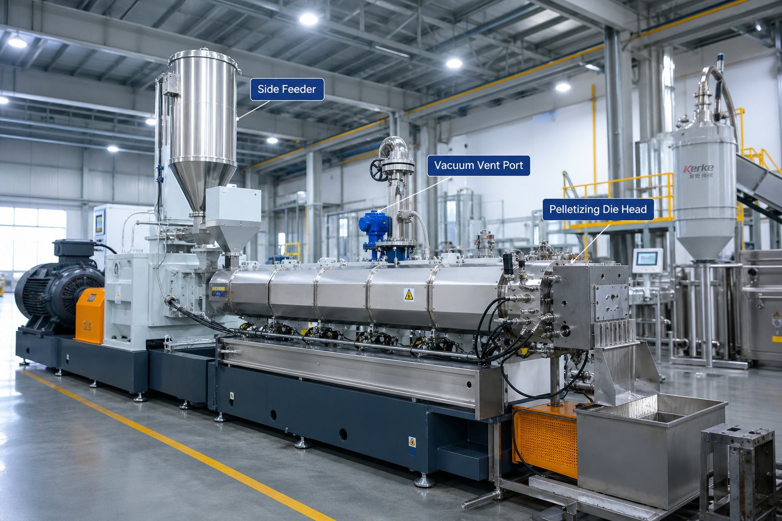
Side feeders introduce secondary materials — mineral fillers, glass fibers, additives, or secondary polymers — into the barrel at a point downstream of the main feed throat. The positioning logic is straightforward: place the side feeder after the primary polymer has fully melted and homogenized, but before the final mixing zone where incorporation needs to happen. This ensures the incoming material meets a stable, low-viscosity melt stream rather than a partially melted mass of pellets.
What happens at the screw level beneath that side feed port, however, determines whether the feeder actually works. The host screw must have long-pitch conveying elements extending 2D to 4D lengths downstream of the side feed opening. These deep-channeled elements serve two purposes: they move the melt past the feed port quickly, maximizing the open volume available for incoming filler, and they prevent backpressure from pushing material up into the feeder throat. If the host screw design causes any buildup of side feed material at the port, it will severely limit the amount of filler you can introduce — no matter how fast your feeder screws turn.
Upstream of the side feed port, you also need partially filled conveying elements. A fully filled screw channel at the feed opening creates a pressurized barrier that blocks filler intake entirely. Starve-fed operation — the default for most co-rotating twin screw plastic extruder systems — naturally keeps upstream channels partially filled, but any restrictive elements placed too close upstream of the port can raise fill levels enough to cause problems.
There is another detail that is easy to overlook: venting. Fillers with low bulk density carry substantial amounts of entrained air into the barrel. That air needs an exit path. The best configuration is an upwardly vented exhaust port positioned just upstream of the side feeder. Some setups use a small half-slit vent built into the upper portion of the feeder housing itself. Without adequate venting, trapped air fluidizes the filler, reduces its effective bulk density even further, and limits feed rates well below what your twin screw auger feeder can theoretically deliver.
Downstream of the side feed port, element selection depends on what you are feeding. For mineral fillers and pigments, a combination of kneading blocks and distributive mixing elements incorporates the material into the melt. For fiber reinforcements, skip the kneading blocks entirely — use TME, SME, or ZME elements that wet and distribute fibers without the intense tip shear that snaps them into useless fragments. The transition from large-pitch conveying at the feed port to downstream mixing elements should be gradual, following the same progressive-intensity principle that governs the main melting zone.
Understanding Restrictive Elements and Melt Seals
Every functional zone boundary in a twin screw extruder screw configuration relies on some form of restriction. Without it, there is nothing preventing material, gases, or pressure from migrating freely between zones — and that migration destroys the controlled processing conditions each zone is designed to provide.
Restrictive elements work by opposing forward flow, which forces the upstream screw channels to fill completely. This fully filled region acts as a melt seal — a pressurized plug of polymer that blocks gas migration and isolates adjacent processing zones. But not all restrictions are created equal. The type of restrictive element you choose determines how aggressively it seals, how much mixing it adds, and how much it raises local melt temperature.
Here is how the three primary restrictive element categories compare, organized by restriction intensity:
- High restriction — Reverse conveying elements: These left-hand helical flights actively push material backward against the main screw flow. The result is the strongest possible melt seal with full backflow opposition. Reverse screw elements slow down the flow of material and are often added before or after kneading elements to increase shear during extrusion. They excel at creating pressure seals upstream of vacuum devolatilization ports, where any leakage would destroy the vacuum and render volatile removal ineffective. The trade-off is significant local temperature rise — material forced backward against forward flow generates intense viscous dissipation. For this reason, best practice limits reverse element length to less than one screw diameter to prevent pressure peaks and excessive thermal stress.
- Moderate restriction — Reverse kneading blocks: Left-hand staggered kneading discs push material backward while simultaneously imparting dispersive and distributive mixing. This makes them a dual-purpose element — they create a meaningful melt seal and provide additional mixing action at the zone boundary. Reverse kneading blocks are particularly useful where you need both a seal and some final homogenization, such as before a second mixing zone in screw extruders running multi-stage compounding profiles. Their restriction is less abrupt than a reverse conveying element, which means the melt temperature rise is more moderate, but the seal is also less absolute.
- Low restriction — Blister rings (throttle elements): Blister rings are smooth, cylindrical elements with a narrow annular gap between the element's outer surface and the barrel wall. Material squeezes through this thin gap under pressure, creating a controlled restriction with minimal mixing action. Because there are no flights or disc transitions, the melt experiences primarily planar shear — not the complex elongational and dispersive shear patterns of kneading blocks. Blister rings are ideal where you need a pressure seal without adding any further mixing energy, such as between two sequential devolatilization stages or in heat-sensitive formulations where every joule of additional shear-generated heat matters.
Choosing between these options is a matter of matching the restrictive element to the specific purpose of the seal. Devolatilization zones typically demand the strongest seals — reverse conveying elements or aggressive reverse kneading blocks — because any vacuum leakage directly compromises product quality. Zone-to-zone transitions within a mixing section may only need moderate restriction from reverse kneading blocks. And thermal-sensitive processes in pharmaceutical or food applications may benefit from the precise, low-energy restriction that blister rings provide.
The interplay between side feeding and restriction is worth noting as well. A melt seal placed upstream of a side feed port — using a reverse element or neutral kneading block — prevents molten polymer from migrating backward into the feeder. Meanwhile, the open conveying section at the port itself ensures filler intake is not obstructed. Getting these two elements to cooperate within just a few diameters of barrel length is one of the tighter configuration puzzles in twin screw extruder design, and it is often the difference between a side feeder that runs at full capacity and one that constantly surges or plugs.
Side feeding and restrictive elements handle the boundaries and interfaces of your screw profile — the places where material enters, zones separate, and pressure differentials must be managed. These are the configuration details that rarely appear in general-purpose design guides, yet they directly determine whether each processing zone functions as intended. With those boundaries properly set, the remaining challenge is balancing the trade-offs that every element selection introduces — trade-offs that shape your final product quality and long-term process economics.
Engineering Trade-offs and Iterative Optimization
Every element swap you make in a screw profile solves one problem while creating another. Add a 90-degree kneading block to improve pigment dispersion? You just raised melt temperature by several degrees and reduced throughput capacity. Replace a reverse element with a blister ring to lower thermal stress? You weakened the melt seal and may have compromised your devolatilization vacuum. This push-and-pull is not a flaw in the design process — it is the design process. Understanding these trade-offs is what separates a functional twin screw extruder screw configuration from an optimized one.
Critical Trade-offs in Element Selection
Imagine you are running a filled polypropylene compound and the lab reports show insufficient filler dispersion. The instinct is to add more aggressive kneading blocks — maybe swap a 45-degree section for 60-degree blocks, or extend the kneading zone by another diameter. That change will almost certainly improve dispersion. But it will also increase the specific energy input and melt temperature, reduce forward conveying capacity, and potentially push your extruder motor closer to its torque limit. Every gain comes with a cost, and the engineer's job is to find the point where the net benefit is maximized.
Here are the four trade-off pairs that govern virtually every configuration decision:
- Mixing intensity vs. throughput capacity: More aggressive mixing elements — steeper stagger angles, narrower kneading discs, longer mixing zones — reduce the net forward pumping action of the screw. Material spends more time in mixing zones and less time moving toward the die. For a given screw speed, this means lower maximum throughput. If your production targets require a specific output rate, you cannot simply pile on kneading blocks without accounting for the throughput penalty.
- Restriction vs. melt temperature: Reverse conveying elements, neutral kneading blocks, and blister rings all oppose forward flow to create melt seals and pressure boundaries. That opposition converts mechanical energy into viscous heat. The more restriction you add, the higher your melt temperature climbs — which is a direct risk factor for thermal degradation of heat-sensitive polymers, discoloration, or decomposition of temperature-sensitive additives. Twin-screw extruder manufacturers often publish maximum recommended melt temperatures for their machines, but the real ceiling is set by the material, not the hardware.
- Kneading section length vs. specific energy and residence time: Longer kneading sections give material more exposure to high-shear zones, improving dispersion quality. But they simultaneously increase specific energy input (more mechanical work per kilogram of material) and broaden the residence time distribution. Broader residence time means some material spends significantly longer in the hot barrel than the average — exactly the condition that causes partial degradation, gel formation, and inconsistent color in the final product.
- Tighter clearances vs. wear rates: Reducing the gap between screw flight tips and the barrel bore intensifies overflight shear, improves self-wiping behavior, and reduces leakage flow. These are all desirable for mixing quality. However, tighter clearances accelerate abrasive wear — especially when processing mineral-filled compounds — and shorten the service life of both screws and barrel liners. A laboratory twin screw extruder running small development batches may tolerate tight clearances for months, but a production machine running 24/7 with 50% glass fiber will chew through those same elements in weeks.
These trade-offs are not independent of each other. Increasing mixing intensity raises melt temperature, which lowers viscosity, which changes shear stress levels, which alters dispersion behavior — creating a chain reaction that ripples through the entire screw profile. That interconnectedness is precisely why isolated element changes so often produce unexpected results.
One metric ties many of these trade-offs together: specific mechanical energy (SME). SME quantifies the total mechanical energy delivered to the material per unit mass, typically expressed in kWh/kg. It is calculated from motor torque, screw speed, and throughput. In a well-controlled process, SME serves as a fingerprint of your configuration's thermal-mechanical impact on the material. A sudden SME shift — even with identical setpoints — signals a change in fill behavior, viscosity, or element wear that demands investigation. For food extrusion, SME directly determines product texture and cook level. For polymer compounding, it correlates with dispersion quality and degradation risk. Monitoring SME run-to-run is one of the most reliable ways to catch configuration-related drift before it shows up in product quality data.
Iterative Optimization and When to Seek Expert Support
Given the interlocking nature of these trade-offs, how do you actually arrive at an optimized screw profile? Not in a single design pass. Screw configuration is refined through systematic iteration — not guesswork, but not a one-shot calculation either.
Screw configuration optimization is inherently iterative — no single configuration is universally optimal, because every change in material, throughput target, or quality specification shifts the balance between competing trade-offs.
The practical methodology follows a structured cycle. Start with a baseline configuration built from the zone-by-zone framework covered earlier in this article. Run that baseline and record four key performance metrics:
- Torque percentage: How much of the motor's available torque the process consumes. Running consistently above 80% leaves no headroom for material viscosity variations or feed rate adjustments. Running below 30% suggests the configuration is under-utilizing the extruder's capacity.
- Melt temperature at the die: The actual temperature the material reaches — not the barrel setpoint, which is often 10 to 30 degrees lower than real melt temperature due to viscous dissipation. Compare this against the material's thermal degradation threshold and your product specification limits.
- Product quality indicators: These vary by application — dispersion rating for filled compounds, residual moisture for devolatilized resins, fiber length distribution for reinforced materials, or dissolution performance for pharmaceutical dispersions. Whatever your critical quality attribute is, measure it quantitatively.
- Throughput stability: Die pressure fluctuation, motor torque variation, and pellet weight consistency all reflect how stable the screw profile operates over time. Instability often points to overly aggressive restrictions, starved zones, or element transitions that create pressure surging.
With baseline data in hand, modify one element zone at a time. If dispersion is insufficient, adjust the kneading section — increase stagger angle, add discs, or switch to narrower disc widths. If melt temperature is too high, shorten a kneading section or replace a reverse element with a less aggressive blister ring. If throughput is limited, increase pitch in conveying sections or reduce the total restrictive element length. The critical discipline is changing only one variable per iteration so you can isolate cause and effect.
This iterative process works well when you have experience with similar materials and extruder sizes. It becomes significantly harder in two scenarios: processing novel materials where rheological behavior is poorly characterized, and scaling between extruder sizes where geometry and operating conditions must be recalculated to preserve the same thermal-mechanical history at a different scale. Research on twin-screw extrusion scale-up confirms that matching process outcomes between a benchtop twin screw extruder and a production machine requires simultaneous consideration of melt temperature profiles, plasticating length, and fill factor distributions — variables that simple geometric scaling rules cannot capture alone.
In these more complex situations, working with experienced screw design specialists can compress months of trial-and-error into a focused development cycle. Engineers who have configured profiles across hundreds of material systems bring pattern recognition that no amount of theoretical knowledge fully replaces. They know, for instance, that a particular nylon grade runs best with a 45-degree-to-60-degree kneading progression rather than a 30-degree-to-90-degree ramp, or that a specific calcium carbonate surface treatment changes the optimal mixing zone length by two diameters. For teams facing these challenges, NANHAIYA's custom screw design services offer tailored screw geometry and material selection recommendations matched to specific polymers, machine conditions, and output requirements — a practical resource for extrusion engineers, machine rebuilders, and production teams who need to accelerate the optimization cycle rather than run it entirely in-house.
The goal of every iteration — whether done independently or with specialist support — is convergence: a configuration where all four performance metrics fall within acceptable ranges simultaneously, not one where chasing a single metric drives the others out of specification. That convergence point is your optimized profile, and it represents the best balance your specific extruder, material, and production targets can achieve. Reaching it efficiently is what transforms screw configuration from a frustrating trial-and-error exercise into a disciplined engineering practice — one that yields measurable, repeatable results you can carry forward into every future project.
Putting Screw Configuration Knowledge into Practice
Convergence on an optimized profile is not the end of the journey — it is the starting point for disciplined, repeatable extrusion performance. Every concept covered in this article, from element taxonomy and stagger angle mechanics to zone sequencing and application-specific strategies, serves a single purpose: giving you the technical framework to make configuration decisions based on engineering logic rather than inherited habit or blind copying of someone else's screw layout.
That framework only delivers value when you internalize its core principles and apply them deliberately. Here is a consolidated list of the ideas that matter most — the ones worth revisiting every time you design, modify, or troubleshoot a screw profile.
Core Screw Configuration Principles to Remember
- Modular element selection drives processing outcomes. Your twin screw extruder screw configuration is not a fixed machine characteristic — it is a variable you control. Conveying elements, kneading blocks, TME, SME, ZME gear elements, and restrictive elements are interchangeable building blocks. Swapping even a few elements changes shear history, residence time, and energy input in ways that barrel temperature and screw speed adjustments alone cannot replicate.
- Stagger angles and element geometry control shear and residence time. A 30-degree kneading block and a 90-degree kneading block occupy the same space on the shaft, yet they create radically different processing conditions. Disc width, stagger angle, and element length together define how aggressively your screw profile transforms material — and understanding those relationships prevents the common trap of over-shearing heat-sensitive formulations or under-mixing demanding ones.
- Zone sequencing follows a logical feed-melt-mix-convey-devolatilize-pump framework. Every functional zone in the barrel has a distinct purpose, and the elements within each zone must match that purpose. Large-pitch conveying at the feed throat, progressive kneading for melting, dispersive and distributive elements for mixing, standard-pitch conveying for melt transport, partially filled channels under vacuum ports for devolatilization, and tight-pitch elements for die pressure buildup. Deviating from this logical progression — skipping a melt seal before a vent port, or placing aggressive kneading blocks in the feed zone — creates problems that no downstream adjustment can fix.
- Application requirements dictate element choices. A plastic twin screw extruder running color masterbatch needs aggressive dispersive kneading. The same machine running glass fiber compounds needs gentle distributive elements downstream of the side feeder. Pharmaceutical hot-melt extrusion demands minimal residence time variation and low thermal stress. Food extrusion uses element selection to target a specific mechanical energy value that controls product texture. The element types are the same across all these applications — but the priorities that guide their selection are entirely different.
- Iterative testing refines any baseline configuration. No screw profile is optimal on the first attempt. Baseline designs built from sound principles get you close, but convergence on the best balance of throughput, melt temperature, product quality, and process stability requires systematic, one-variable-at-a-time modification guided by measured performance data. Treat SME monitoring, torque tracking, and melt temperature measurement as non-negotiable tools in this process.
- Hidden parameters set physical boundaries. Free volume determines devolatilization capability and maximum feed rate. OD/ID ratio governs the fundamental trade-off between shear intensity and volumetric capacity. Meshing clearances affect self-wiping behavior, leakage flow, and component wear life. These geometric constraints are baked into your screw and barrel hardware — and ignoring them means designing profiles that exceed the physical limits of your equipment.
This article was built to occupy the space between two extremes that most engineers encounter when researching twin-screw extruders: manufacturer brochures that oversimplify element selection into a few bullet points, and academic papers locked behind paywalls that bury practical guidance under simulation methodology. Neither extreme serves the process engineer who needs to design, troubleshoot, or improve a real screw profile for a real production line. The principles above are meant to bridge that gap — technical enough to guide real decisions, practical enough to apply on the shop floor.
Next Steps for Your Configuration Project
If there is one takeaway worth carrying into your next project, it is this: approach screw configuration as a systematic engineering discipline. Document your baseline profiles. Record the performance metrics for every configuration change. Build an internal library of what works for each material family, and treat that library as institutional knowledge worth protecting and expanding.
Some configuration challenges, though, demand more than internal iteration. Novel polymer systems with poorly characterized rheology, scale-up projects moving from a laboratory or benchtop machine to full production, or legacy twin-screw extruders being repurposed for entirely new material families — these situations benefit from external expertise. Twin screw extruder manufacturers can provide starting-point recommendations, but they typically stop short of application-specific optimization for your exact formulation and quality targets.
For teams that need screw geometry, material selection, or processing recommendations tailored to specific polymers, machine conditions, and output requirements, NANHAIYA's custom screw design services offer a practical resource. Their engineering team works with extrusion engineers, machine rebuilders, and production teams to develop screw profiles matched to real-world operating constraints — not generic catalog recommendations, but configurations informed by the kind of application-specific thinking this article advocates. Whether you are configuring a new compounding line, retrofitting worn elements, or scaling a proven profile to a larger machine, having a screw design partner who understands the trade-offs covered here can compress your optimization timeline significantly.
The science and practice of screw configuration will continue evolving. New element geometries emerge as computational modeling tools improve. Advanced wear-resistant coatings extend element service life in abrasive applications. Simulation-driven design is steadily reducing — though not eliminating — the number of physical iterations needed to reach an optimized profile. And as materials science pushes processors toward increasingly demanding formulations — bio-based polymers, recycled feedstocks with variable quality, nano-filled composites — the screw profiles that worked five years ago will not meet tomorrow's requirements.
That reality is not a burden. It is exactly why mastering the fundamentals of screw configuration pays compound returns. The engineer who understands element function, stagger angle mechanics, zone sequencing logic, and iterative optimization methodology is not locked into yesterday's designs. They are equipped to adapt — methodically, confidently, and with measurable results — to whatever processing challenge comes next.
FAQs About Twin Screw Extruder Screw Configuration
1. What is a twin screw extruder screw configuration?
A twin screw extruder screw configuration is the deliberate arrangement and sequencing of modular screw elements — conveying elements, kneading blocks, and specialized mixing elements — along a splined shaft. Each element type performs a specific function such as feeding, melting, dispersive or distributive mixing, devolatilization, and pressure buildup. By changing the order, type, and geometry of these interchangeable building blocks, engineers control residence time distribution, shear history, and energy input, which are the three primary drivers of final product quality. The same extruder barrel can yield dramatically different processing results simply by rearranging the elements on the shaft.
2. How do kneading block stagger angles affect mixing performance?
Kneading block stagger angle is the angular offset between adjacent disc lobes, and it directly controls the balance between forward conveying and shear intensity. A 30-degree stagger provides gentle mixing with strong forward pumping, suitable for initial melting. A 45-degree stagger offers moderate shear and reliable conveying for general-purpose melting. A 60-degree stagger delivers high shear with weak forward conveying, ideal for demanding pigment or filler dispersion. A 90-degree neutral stagger eliminates forward pumping entirely, maximizing shear and residence time to function as a restrictive element. Reverse-staggered kneading blocks push material backward, creating pressure seals essential for devolatilization zones.
3. What is the difference between dispersive and distributive mixing in twin screw extrusion?
Dispersive mixing relies on high shear stress to break apart agglomerates, reduce droplet sizes, or fracture particle clusters. Kneading blocks with steep stagger angles (60 and 90 degrees) and narrow disc widths are the primary dispersive mixing tools. Distributive mixing, on the other hand, splits and recombines the melt to spread already-fine domains evenly throughout the matrix without applying excessive force. Specialized elements like TME (tooth mixing elements), SME (screw mixing elements), and ZME (gear mixing elements) are designed for this purpose. Most real-world formulations require both modes sequenced in the correct order — dispersive elements first to break agglomerates, followed by distributive elements to homogenize. For expert help selecting the right element combination for your formulation, NANHAIYA's custom screw design services at nhyscrews.com can provide tailored recommendations.
4. How do you design a twin screw extruder screw profile from scratch?
Designing a screw profile follows a systematic zone-by-zone approach. Start with large-pitch conveying elements in the feed zone for smooth material intake. Transition to progressively more aggressive kneading blocks (30 to 60 or 90 degrees) in the melting zone. Add dispersive and distributive mixing elements tailored to your formulation in the mixing zone. Use standard-pitch conveying elements for melt transport. Place melt seals (reverse elements or neutral kneading blocks) upstream of vacuum ports, with large-pitch partially filled elements beneath vent openings for devolatilization. Finish with tight-pitch conveying elements for die pressure buildup. After establishing a baseline, optimize iteratively by modifying one zone at a time and measuring torque, melt temperature, product quality, and throughput stability.
5. What role do OD/ID ratio and free volume play in screw configuration?
OD/ID ratio (outer-to-inner screw diameter) and free volume are hidden geometric parameters that set the physical boundaries of what a screw profile can achieve. A higher OD/ID ratio (1.55-1.66) creates shallower channels with higher shear rates but lower throughput capacity — ideal for intensive compounding. A lower ratio (1.20-1.40) provides deeper channels with higher volumetric capacity but reduced shear, suited for high-throughput or micro-batch applications. Free volume is the open cross-sectional area available for material in the screw channel. High free volume is essential for effective devolatilization because it enables thin melt films with high surface renewal under vacuum. Together, these parameters influence conveying capacity, fill level, shear intensity, and volatile removal efficiency across the entire screw profile.
Written by
Nanhaiya Technical Team
Zhoushan Nanhaiya Plastic Machinery Co., Ltd.
The Nanhaiya technical team supports screw and barrel manufacturing projects through application review, technical communication, custom manufacturing coordination, and production and quality control.
Discuss Your Application
Related Articles
More insights on screw barrel technology and plastics processing.
Your Extruder Feeding Instability Isn't Random — Here's Why
Oct 22, 2026
Extruder feeding instability causes surging output and scrap. Learn the 6 root causes, polymer-specific fixes, wear diagnostics, and preventive protocols.
Read Article
Parallel Twin Screw Extruder for Compounding Demystified: Lab to Line
Oct 21, 2026
Learn how a parallel twin screw extruder for compounding works—from screw element design and zone configuration to lab-to-production scale-up and process optimization.
Read Article
Twin Screw Extruder for PVC: The Setup Mistake Draining Profit
Oct 21, 2026
Learn how to match twin screw extruder configurations to PVC applications. Covers conical vs parallel, counter-rotating vs co-rotating, wear management, and troubleshooting.
Read ArticleLooking for something else?
Search by material, symptom or product and jump straight to the relevant page.
These are navigation suggestions based on keyword matching — not a quotation, not a delivery commitment, and not a substitute for engineering review. Final specification is confirmed by our engineers against your drawings and processed material.
Need help with screw barrel selection?
Share your machine model, processed material and application. Our team can help with pricing and technical support.