

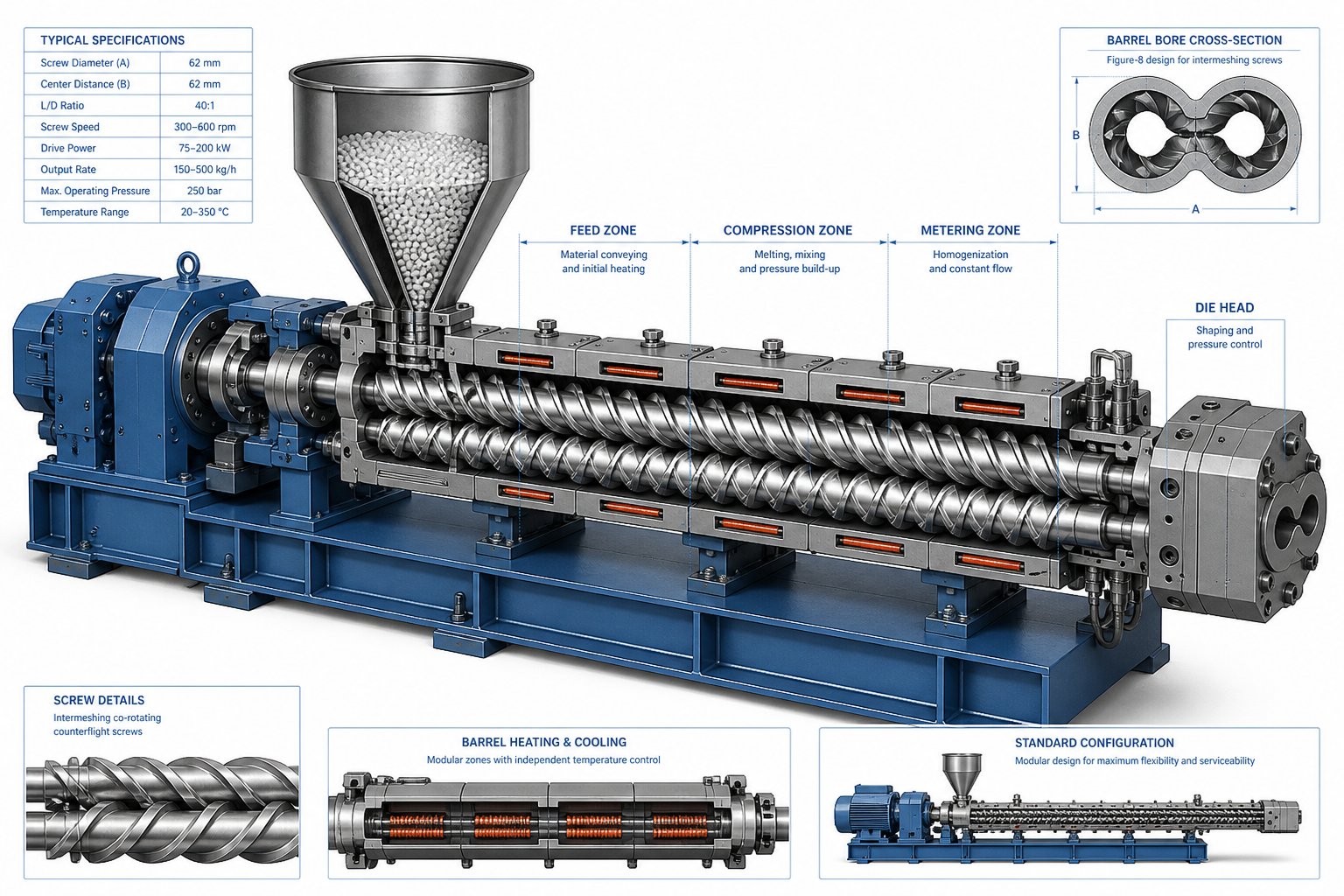
What a Twin Screw Extruder Schematic Reveals
You've probably seen one pinned to a workshop wall or buried in an OEM manual — a detailed diagram showing every zone, element, and flow path of a twin screw extruder, from the motor all the way to the die head. But have you ever stopped to really read it? Most resources explain what a twin-screw extruder does. Very few teach you how to decode the schematic itself. That gap costs engineers hours of guesswork and operators unnecessary headaches during troubleshooting.
This guide changes that. It's built to turn you into a confident reader of twin screw extruder schematics, whether you're specifying new equipment, ordering replacement screw elements, or diagnosing a processing issue on the plant floor.
Defining the Twin Screw Extruder Schematic
Before diving into the details, let's anchor a clear definition:
A twin screw extruder schematic is a scaled engineering drawing or diagram that maps every functional zone, modular component, and material flow path of a twin screw extruder — from the drive system through segmented barrel zones to the die head — using standardized symbols, annotations, and cross-sectional views.
Think of it as the machine's visual language. Every numbered barrel zone, every kneading block notation, and every directional arrow carries specific meaning about how materials move, melt, mix, and exit the extruder.
Why Schematics Matter in Extrusion Engineering
A twin screw schematic isn't just a reference poster. It's a working document that drives real decisions across multiple teams:
- Machine assembly: Technicians rely on the schematic to position barrel segments, venting ports, and side feeders in the correct sequence.
- Screw element ordering: Procurement teams use element codes from the screw profile layout to source exact replacements.
- Troubleshooting: When an operator encounters surging, poor melt quality, or vent flooding, the schematic pinpoints which zone or element to investigate.
- Process optimization: Engineers redesign screw configurations on the schematic before ever pulling a single element off the shaft.
Whether you're working with a lab-scale twin-screw extruder or a full production line, schematic literacy is the foundation for every conversation about configuration, performance, and component sourcing. The challenge, of course, is knowing what each symbol, zone label, and element notation actually means — and that starts with identifying the major components laid out across the drawing.
Major Components on a Labeled Twin Screw Extruder Schematic
Every twin screw extruder schematic reads like a map — left to right, drive end to discharge end. When you follow that path systematically, the machine stops looking like a confusing assembly of rectangles and arrows and starts revealing its logic. Let's walk through each major section in the order you'll encounter it on the drawing.
Drive System and Power Transmission
The leftmost block on most schematics represents the drive system. You'll typically see a motor symbol connected to a gearbox through a coupling, with directional arrows indicating torque transfer into the screw shafts. The gearbox notation often includes a ratio — something like 1:1.5 — which tells you how the motor's speed is reduced and torque amplified before reaching the screws. Thrust bearings appear immediately after the gearbox, absorbing the axial forces generated by material pressure inside the twin screw barrel. If you notice a "specific torque" value annotated nearby, that figure is a key performance indicator: higher specific torque enables greater throughput and filler loading capacity.
Feed Section and Hopper Assembly
Moving rightward, you'll reach the feed throat — an open barrel section where raw materials enter the screw extruder. On the schematic, the hopper sits above this opening with a downward flow arrow showing material dropping onto the screws. Feeder connections are drawn here too, typically labeled as gravimetric (loss-in-weight) or volumetric, depending on the precision required. One detail worth watching for: some schematics mark the feed zone as water-cooled only, with no heating element. This prevents premature melting that could cause material to stick and bridge in the throat. When processing low-bulk-density powders, you may even see two adjacent open barrels — the first acting as a back vent so entrained air can escape without blocking the feed chute.
Segmented Barrel Zones and Screw Shaft
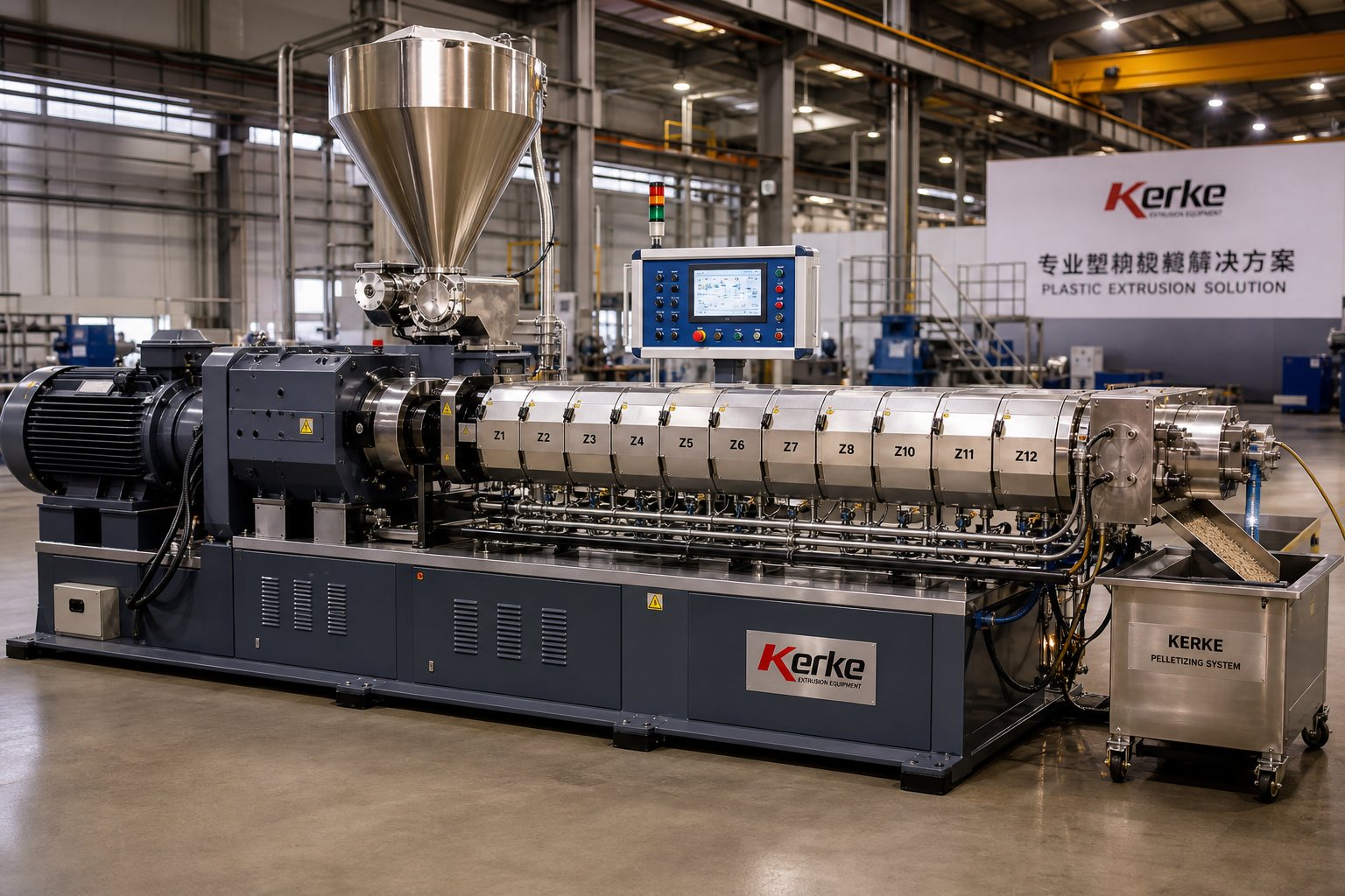
The heart of a twin screw extruder machine schematic is its segmented barrel layout. Each barrel section is numbered sequentially — Zone 1, Zone 2, Zone 3, and so on — with individual temperature setpoints annotated below. Heating elements and cooling channels are marked alongside each zone, indicating independent thermal control. Cross-sectional views reveal the signature figure-8 bore profile where the two intermeshing screws sit, fundamentally different from the single cylindrical bore of a single-screw extruder.
Here's a breakdown of every major component category you should be able to identify on a labeled schematic:
- Drive unit: Motor, gearbox, coupling, and thrust bearings — drawn as a connected block at the far left.
- Feed throat: Open barrel section with hopper symbol and feeder connection above.
- Barrel segments: Sequentially numbered closed sections, each showing heating and cooling annotations.
- Venting ports (atmospheric and vacuum): Open barrel sections marked ATM or VAC, indicating volatile removal points.
- Side feeder positions: Secondary figure-8 openings on the barrel side, connected to twin-screw side stuffers.
- Screw shaft with modular elements: A horizontal bar spanning the full barrel length, populated with conveying elements, kneading blocks, and reverse elements drawn to scale.
- Die head or pelletizing adapter: The terminal block at the far right, shaped to match the downstream equipment (strand die, underwater pelletizer, or profile die).
Most twin screw and barrel assemblies on industrial machines span 10 to 13 barrel sections, giving an L/D ratio in the range of 40:1 to 52:1. Each segment typically measures four to six screw diameters in length, which is why you'll see consistent, modular spacing across the drawing.
Venting Ports, Side Feeders, and Die Head
Toward the discharge end of the schematic, you'll encounter one or more venting zones. Atmospheric vents appear as simple open barrel sections — often positioned just upstream of a side feeder to release entrained air when fillers or additives are introduced. Vacuum vents, usually located one or two barrel sections before the die, connect to a vacuum pump symbol and are annotated with target pressure levels. Their purpose is devolatilization: removing moisture, residual monomers, or reaction byproducts from the melt before it exits the machine.
Side stuffers show up as perpendicular twin-screw feeder connections mounted on a dedicated side-feed barrel or combi-barrel that includes both a feed port and a compact upstream vent. These allow downstream addition of glass fibers, mineral fillers, or other additives directly into the molten polymer without disrupting the upstream melting process.
At the far right of the schematic sits the die head. Its shape varies by application — a multi-hole strand die for pelletizing, an annular die for pipe extrusion, or a flat die for sheet production. Pressure transducer symbols typically appear just before the die entrance, giving operators a critical reading of melt pressure at the point of discharge. Between the last barrel zone and the die, you may also see a screen changer or melt filter drawn inline, particularly on recycling or filled-compound lines where contaminant removal is essential.
With every major component identified and located, the next challenge is understanding the symbols and shorthand that engineers use to annotate these elements — the notational language that turns a diagram into a fully readable technical document.
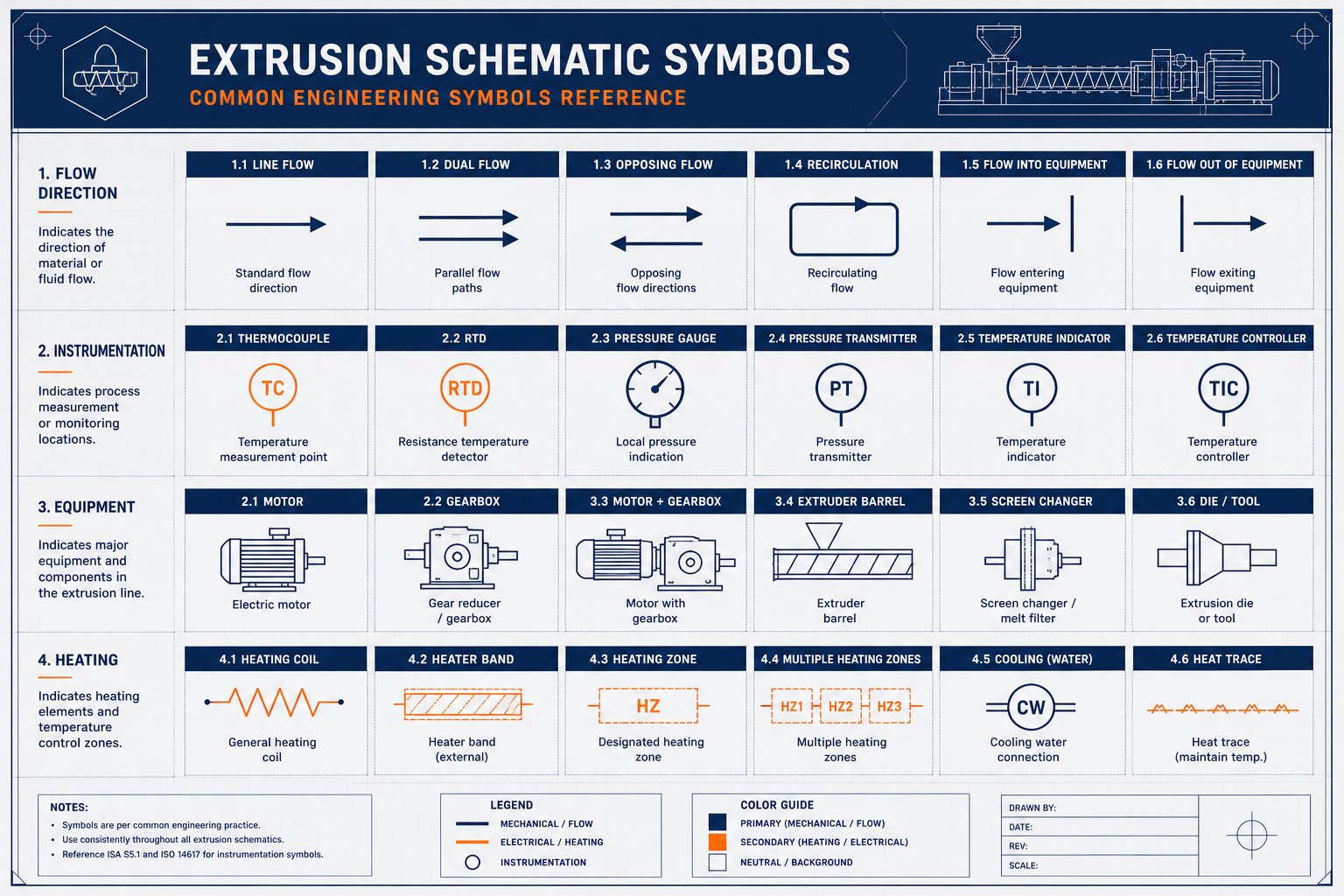
Schematic Annotation Key and Engineering Symbols for Twin-Screw Extruders
Identifying components on a schematic is one thing. Understanding the shorthand scrawled next to them is something else entirely. Every extruder twin screw drawing is packed with abbreviations, directional markers, and element codes that compress complex engineering information into compact labels. Treat this section as your pocket decoder — a mini-reference you can return to whenever you encounter unfamiliar notation on an OEM document, technical paper, or shop-floor drawing.
Standard Engineering Symbols and Flow Arrows
The most universal feature on any twin screw extruder schematic is the directional flow arrow. It runs left to right, tracing material movement from the feed throat to the die head. You'll also spot smaller arrows at the drive end indicating screw rotation direction — and this is where things get functionally important. When both arrows point the same way (both clockwise or both counterclockwise as viewed from the drive end), you're looking at a co-rotating configuration. When they point in opposite directions, the machine is counter-rotating.
Beyond flow and rotation, keep an eye out for these sensor and equipment symbols scattered along the barrel zones:
- Thermocouple markers: Small triangular or diamond-shaped icons inserted into barrel walls, indicating where temperature measurements are taken within each zone.
- Pressure transducer icons: Circular or rectangular gauge symbols, most commonly positioned near the die entrance and sometimes at key mid-barrel locations.
- Motor and gearbox representations: Typically drawn as a circle (motor) connected to a rectangular block (gearbox), with gear ratio and torque values annotated alongside.
- Heating and cooling indicators: Zigzag lines or coil symbols for electric heaters, and parallel channel lines for liquid cooling circuits — each paired with a specific barrel zone number.
Zone Labeling Conventions and Abbreviations
Imagine opening a screw profile document and seeing labels like "BZ-4," "KB45/5/30," or "VAC" without any legend. Confusing? It doesn't have to be. Most twin-screw extruders follow consistent abbreviation conventions across OEM documentation, even though exact formatting can vary between manufacturers. The table below covers the notations you'll encounter most frequently:
| Symbol / Abbreviation | Full Name | Where It Appears on the Schematic |
|---|---|---|
| BZ | Barrel Zone | Below each numbered barrel segment (e.g., BZ-1, BZ-2) |
| SE or CE | Screw Element / Conveying Element | Along the screw profile bar in feed and transport zones |
| KB or KBW | Kneading Block (Wide) | In mixing and melting zones on the screw profile layout |
| KP | Kneading Block with Half Disks | Mixing zones; noted with stagger angle and disc count |
| RE or L-suffix | Reverse Element (Left-hand rotation) | Upstream of vent zones and before die — creates melt seals |
| GFM | Gear-type Mixing Element | Distributive mixing zones, often downstream of kneading sections |
| Z | Toothed Mixing Element | Low-shear distributive mixing zones on the screw profile |
| ATM | Atmospheric Vent | Open barrel sections for releasing entrained air or light volatiles |
| VAC | Vacuum Vent | Barrel sections connected to vacuum pump symbols for devolatilization |
| OD/ID | Outer Diameter / Inner Diameter Ratio | General specifications box or header annotation on the schematic |
A quick note on the "R" and "L" suffixes you'll see appended to element codes: "R" denotes right-hand (forward-conveying) rotation, while "L" indicates left-hand (reverse) rotation. This single letter changes everything about what the element does inside the barrel — forward conveyance versus backpressure and melt sealing.
Screw Element Notation Systems
Here's where the notation gets especially dense — and especially powerful once you crack the code. Twin screws use modular elements, and each one carries an alphanumeric identifier that encodes its geometry in a compact format.
For conveying elements, the notation typically follows a pitch/length structure. An element labeled SE 30/30 R tells you the pitch is 30 mm, the segment length is 30 mm, and the rotation direction is right-hand (forward). A tighter pitch like SE 10/20 R means the screw flight wraps more tightly — 10 mm pitch over a 20 mm length — producing higher pressure buildup and slower forward conveyance. As NC State Extension's screw design reference explains, the first number represents the flight pitch and the second represents the segment length in millimeters.
For kneading blocks, the notation adds two more variables: stagger angle and disc count. A label like KBW 45/5/30 R breaks down as follows:
- 45 — the angular offset (stagger angle) between adjacent discs
- 5 — the number of discs in the block
- 30 — the total length of the element in millimeters
- R — right-hand (forward) conveying direction
Change that "R" to an "L" and the same kneading block reverses its conveying effect, pushing material backward and dramatically increasing shear and residence time.
For toothed mixing elements, the convention shifts slightly. An element coded Z 8/3/20 indicates 8 teeth, 3 tooth rows, and a 20 mm element length. These elements provide gentle distributive mixing with virtually no dispersive shear — useful when you need homogeneity without degrading heat-sensitive materials.
Keep in mind that notation systems vary between manufacturers. Brabender, Leistritz, Coperion, and other OEMs each apply slightly different prefixes and formatting conventions. The underlying logic, however, remains consistent: geometry encoded as numbers, function encoded as letters. Once you internalize that pattern, you can read screw profiles from virtually any extruder twin screw supplier — and more importantly, you can start connecting those element codes to the functional zones they occupy along the full screw profile.
Screw Element Types Mapped Along the Twin Screw Extrusion Profile
Knowing what each element code means is a solid start. But a string of alphanumeric labels only tells half the story. The real insight comes from understanding where each element type sits along the screw profile — and why it belongs there. In twin screw extrusion, the sequence of elements from feed to die isn't random. It follows a deliberate engineering logic: convey, melt, mix, vent, pressure-build, discharge. Every element on the schematic occupies a position that serves one or more of those functions.
Imagine the screw profile as a timeline of what happens to your material. At the feed end, loose pellets or powder drop onto the screws. By the discharge end, a homogeneous, devolatilized melt exits under pressure. The elements arranged between those two points control every transformation along the way — temperature rise, shear intensity, residence time, and mixing quality. Let's map each category onto that timeline.
Conveying Elements and Their Schematic Placement
Conveying elements are the workhorses of the twin screw extrusion process. They appear as helical flight segments on the schematic and occupy more total length than any other element type — typically 50% to 60% of the full screw profile. Their job is straightforward: move material forward along the barrel without imparting significant shear or mechanical energy.
You'll find conveying elements concentrated in three key positions on the schematic:
- Feed zone (L/D 0–8): Open-pitch elements with large channel depth dominate here. A wide pitch — such as SE 40/40 R or SK 40/40 R — maximizes free volume and conveying capacity, pulling solid material away from the feed throat quickly to prevent bridging and backup.
- Transport zones between functional sections (variable L/D): Medium-pitch conveying elements bridge the gaps between kneading blocks, venting ports, and side feeders. They give the material a chance to travel forward before encountering the next high-shear or restrictive zone.
- Pre-die metering zone (final 4–6 L/D): Tighter-pitch elements — something like SE 10/20 R — appear near the discharge end. Their compressed flight spacing builds pressure to push melt through the die head or screen changer.
The pitch variation you see on the schematic carries direct process meaning. A wide-pitch element (high first number in the notation) moves material faster, keeps the channel partially filled, and generates minimal pressure. A tight-pitch element slows forward conveyance, fills the channel more completely, and builds the pressure needed for downstream operations. As NC State Extension's screw design publication notes, the deeper channel flights of conveying elements enable efficient material transport without imparting shear or breaking down ingredients — a critical distinction from the kneading and mixing elements that follow downstream.
One detail that trips up newcomers: the self-wiping geometry of co-rotating twin screws means conveying elements on both shafts intermesh tightly. On the schematic's cross-sectional view, you'll see the flights of one screw nested into the channels of the other. This geometry prevents material from stagnating in dead zones — a feature that single-screw schematics simply don't show.
Kneading Blocks at Various Stagger Angles
If conveying elements are the highways, kneading blocks are the processing plants along the route. They appear on the screw profile schematic as a series of disc-shaped lobes — visually distinct from the helical flights of conveying elements — and their placement marks the zones where melting, mixing, and energy input actually happen.
The stagger angle between adjacent discs determines how aggressively each kneading block works the material. A block with a shallow angle still pushes material forward while gently folding it. A block at 90 degrees stops all forward conveyance entirely, forcing the melt to dwell and absorb maximum mechanical energy. The table below maps each common configuration to its function and typical position along a twin screw compounding extruder profile:
| Element Type | Stagger Angle | Primary Function | Typical Schematic Position (L/D Range) |
|---|---|---|---|
| Forward kneading block (KB 30°) | 30° | Gentle distributive mixing; strong forward conveyance; initial softening of solids | L/D 6–10 (entry to melting zone) |
| Forward kneading block (KB 45°) | 45° | Moderate mixing with moderate forward conveyance; balances shear and throughput | L/D 8–14 (mid-melting zone or secondary mixing) |
| Forward kneading block (KB 60°) | 60° | Strong shear and energy input; limited forward conveyance; primary melting element | L/D 8–14 (core melting zone) |
| Neutral kneading block (KB 90°) | 90° | Maximum energy input; zero forward conveyance from rotation; acts as flow restriction and melt dam | L/D 12–16 (end of melting zone or intensive mixing zone) |
| Reverse kneading block (KB 45° LH or 60° LH) | 45° or 60° (left-hand) | Pushes material upstream; creates backpressure and melt seal; ensures full melting | L/D 14–18 (immediately before vent zones) |
Notice the progression. On a typical schematic for screw extrusion, you'll see 30° blocks positioned first in the melting section, easing the transition from conveying elements. Then 60° blocks take over to deliver the primary mechanical energy that softens and melts the polymer. Finally, 90° neutral blocks — or even reverse kneading blocks — cap the melting section to act as a dam, ensuring no unmelted particles slip through. Industry guidance from Plastics Technology confirms this sequencing logic: the 30° kneading block helps pull feed into the melting zone with minimal backflow, the 60° blocks provide stronger work input to begin melting, and the 90° blocks serve a dual role as energy maximizers and flow restrictors that increase local residence time.
Disc width adds another visual layer. Schematics sometimes show narrow-disc kneading blocks — more discs packed into the same element length — versus wide-disc blocks with fewer, broader paddles. Wider discs act more like plows, forcing polymer over the disc tip and through the high-shear gap between tip and barrel wall. Narrow discs slice through the melt in a scissoring action, favoring gentle redistribution over aggressive particle breakdown. When you see a kneading block on the schematic with six or seven thin discs versus one with three or four thick ones at the same total length, you're looking at a distributive element versus a dispersive one — even if both carry the same stagger angle.
Reverse Elements and Specialized Mixing Elements
Reverse-pitch conveying elements and reverse kneading blocks are the gatekeepers of the screw profile. On the schematic, they're easy to spot once you know what to look for: their flight or disc orientation is the mirror image of their forward counterparts, and many manufacturers append "LH" (left-hand) or "L" to the element code. A reverse conveying element like SE 20/20 L pushes material backward against the main flow direction, creating a high-pressure melt seal that completely fills the barrel channel at that location.
Why does that matter? Because melt seals are essential for two critical process steps visible on the schematic:
- Vacuum venting: A reverse element positioned just upstream of a vacuum vent zone ensures the screw channels in the vent section remain only partially filled. This partially filled condition exposes maximum melt surface area to the vacuum, dramatically improving devolatilization efficiency. Without the melt seal, vacuum would pull upstream through fully open channels, destroying the pressure differential the process depends on.
- Isolating process zones: Reverse elements create pressure barriers that separate the melting zone from the mixing zone, or the mixing zone from the discharge zone. On a twin screw compounding extruder schematic, you can often count the number of reverse elements to determine how many functionally independent processing sections the designer intended.
Beyond standard reverse elements, schematics for advanced twin screw extruders may include specialized mixing elements that occupy their own visual niche on the profile layout. Two of the most common are:
- GFM (gear-type mixing elements): Drawn as interlocking gear-tooth patterns on the screw profile, these elements provide excellent distributive mixing with minimal pressure drop. Material flows through the gear teeth and is repeatedly split, reoriented, and recombined — spreading additives uniformly throughout the melt without generating the high shear that could degrade heat-sensitive polymers or break fragile fillers like glass fibers.
- Toothed mixing elements (Z-type): These appear as short, cylindrical segments with radial teeth or pins on the schematic. Coded with a format like Z 8/3/20 — indicating 8 teeth, 3 tooth rows, and 20 mm length — they deliver distributive mixing with virtually no dispersive shear. Their typical schematic position falls in the downstream mixing zone, after the polymer is fully molten and additives have been introduced through a side feeder.
The distributive versus dispersive distinction is worth internalizing because it shapes how you interpret the schematic's intent at any given L/D position. Distributive elements — GFM gears, narrow-disc kneading blocks, and toothed mixers — spread material evenly without breaking particles down. Dispersive elements — wide-disc 90° kneading blocks and reverse kneading blocks — apply high shear stress to rupture agglomerates and break cohesive clumps into their primary particle size. Plastics Technology's compounding series illustrates this clearly: wide-disc kneading blocks plow through the polymer, forcing material over disc tips through the highest-shear gap in the extruder, while narrow-disc blocks slice through the melt with a scissoring motion that gently redistributes components.
When you look at a complete screw profile on a schematic, the interplay between these element types reveals the designer's full processing strategy: where energy enters the melt, where particles get broken down, where additives get folded in, and where pressure barriers compartmentalize each step. That same schematic, however, looks fundamentally different depending on whether the machine uses co-rotating or counter-rotating screws — a distinction that changes not just the rotation arrows on the drawing, but the entire geometry and element layout beneath them.
Co-Rotating vs Counter-Rotating Twin Screw Extruder Schematic Differences
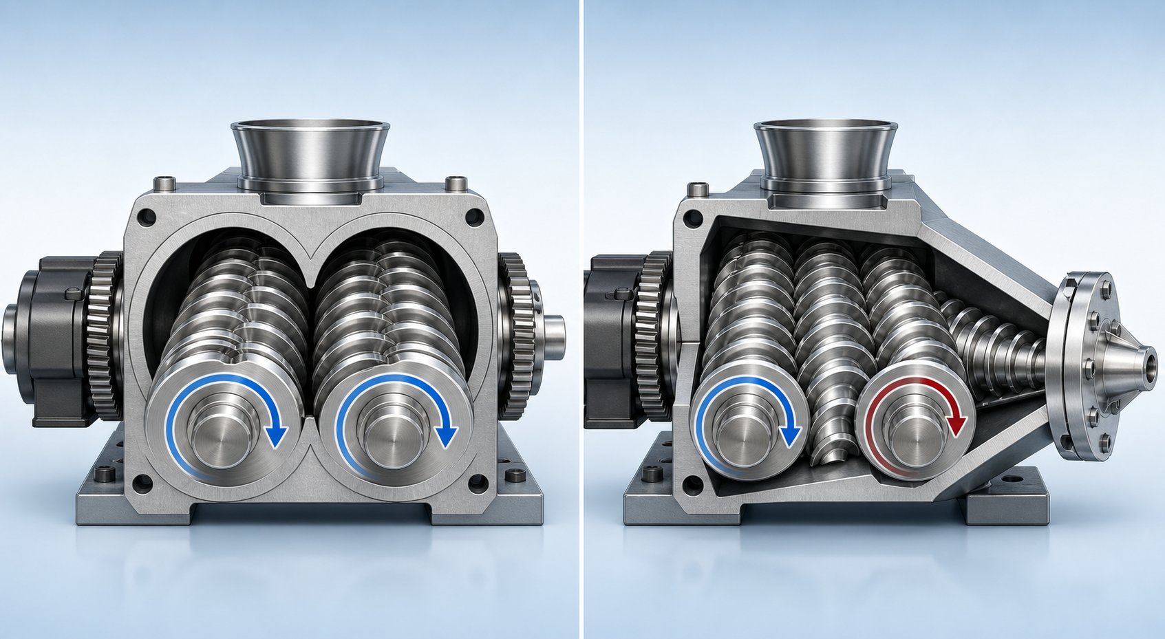
Two twin screw extruder schematics can sit side by side on your desk and look almost identical at first glance — same left-to-right layout, same barrel zone numbering, same general shape. But look closer at the rotation arrows, the barrel cross-section, and the screw element arrangement, and you'll realize you're reading two fundamentally different machines. The distinction between a co rotating twin screw extruder and a counter-rotating one isn't just a matter of which way the shafts spin. It reshapes the entire geometry of the drawing — and the processing logic behind it.
Co-Rotating Parallel Twin Screw Schematic Layout
On a co-rotating parallel twin screw extruder schematic, both rotation arrows at the drive end point in the same direction — either both clockwise or both counterclockwise as viewed from the motor side. The barrel cross-section shows a symmetrical figure-8 bore, and both screws share identical diameters along their full length.
What makes this configuration visually distinctive on the screw profile layout is the density of kneading block zones. Co-rotating designs use a fully intermeshing, self-wiping geometry where each screw flight cleans the surface of its partner. This self-wiping action — which eliminates dead zones and keeps the residence time distribution narrow — enables engineers to load the profile with aggressive mixing elements. You'll typically see multiple kneading block sections at varying stagger angles, interspersed with reverse elements that create melt seals before venting zones.
The co rotating twin screw extruder dominates applications demanding intensive mixing: polymer compounding with fillers, reactive extrusion involving in-line chemical reactions, devolatilization of moisture-sensitive resins, and masterbatch production. On the schematic, these applications translate into longer L/D ratios (commonly 40:1 to 52:1), more barrel zones, and a modular screw profile packed with functional variety. As Technovel's engineering column explains, the intense shear fields that develop between co-rotating screws and between screw and barrel — combined with the elongational flow component from kneading blocks — impose a complex deformation history on the material that's unmatched by other configurations.
Counter-Rotating Conical and Parallel Schematics
Flip one of those rotation arrows, and the schematic tells a very different story. On a counter-rotating extruder drawing, the two arrows at the drive end point in opposite directions — one clockwise, one counterclockwise. This seemingly small visual change reflects a major shift in how material moves through the machine.
Counter-rotating configurations split into two sub-types, each with a distinct schematic appearance:
- Parallel counter-rotating: Both screws maintain the same diameter from feed to discharge, just like their co-rotating cousins. The barrel cross-section still shows a figure-8 bore, but the intermeshing zone behaves differently — material is drawn between the screws and compressed in a calendering action rather than being wiped from one flight to the next. This gentler mechanism produces lower shear stress, which suits thermally sensitive materials like rigid PVC.
- Conical counter-rotating: This is where the schematic looks unmistakably different. The conical twin screw extruder drawing shows a barrel that visibly narrows from feed end to discharge end — the screws taper from a larger diameter at the hopper to a smaller diameter at the die. This tapered geometry creates a natural compression zone and eliminates the need for separate pressure-building elements near the die. Conical designs are a staple in PVC pipe and profile extrusion lines.
Screw profiles on counter-rotating schematics tend to look simpler than co-rotating ones. You'll see fewer kneading block zones because the calendering effect at the intermeshing region already provides sufficient dispersive mixing for many formulations. Technovel notes that counter-rotating machines rely primarily on compressive and elongational deformation rather than the high-shear fields characteristic of co-rotating designs — a processing philosophy that allows extrusion at lower temperatures while suppressing heat-induced degradation.
Key Visual Differences at a Glance
When you're comparing co rotating and counter rotating twin screw extruder schematics, the differences cluster around six observable features. The table below puts them side by side so you can identify any configuration at a glance:
| Feature | Co-Rotating Parallel | Counter-Rotating Parallel | Counter-Rotating Conical |
|---|---|---|---|
| Rotation Direction | Both screws same direction | Screws in opposite directions | Screws in opposite directions |
| Barrel Cross-Section Shape | Symmetrical figure-8 bore | Symmetrical figure-8 bore | Tapered figure-8 bore (narrows toward die) |
| Screw Geometry on Schematic | Constant diameter; fully intermeshing self-wiping profile | Constant diameter; intermeshing with calendering gap | Tapered diameter from large (feed) to small (die) |
| Typical L/D Ratio Range | 32:1 to 52:1 | 22:1 to 40:1 | 17:1 to 26:1 |
| Intermeshing Type | Fully intermeshing, self-wiping | Fully or partially intermeshing, non-self-wiping | Fully intermeshing, non-self-wiping |
| Primary Applications | Compounding, reactive extrusion, devolatilization, masterbatch | PVC profiles, pipes, sheets; heat-sensitive materials | PVC pipe, profile extrusion; medium-capacity lines |
Notice how the L/D ratio ranges shrink dramatically from co-rotating parallel to conical counter-rotating designs. That's not arbitrary — it reflects the processing philosophy encoded in each schematic. Co-rotating machines need longer barrels to accommodate multiple kneading, venting, and side-feeding zones for complex compounding tasks. Conical designs achieve compression and melting through geometry alone, requiring fewer barrel sections to accomplish the same pressure buildup.
These configuration-level differences set the stage for another critical reading skill: understanding the screw configuration chart — that detailed horizontal layout showing every individual element, barrel temperature, and L/D position arranged in sequence from feed to die.
Reading the Screw Profile and Configuration Chart
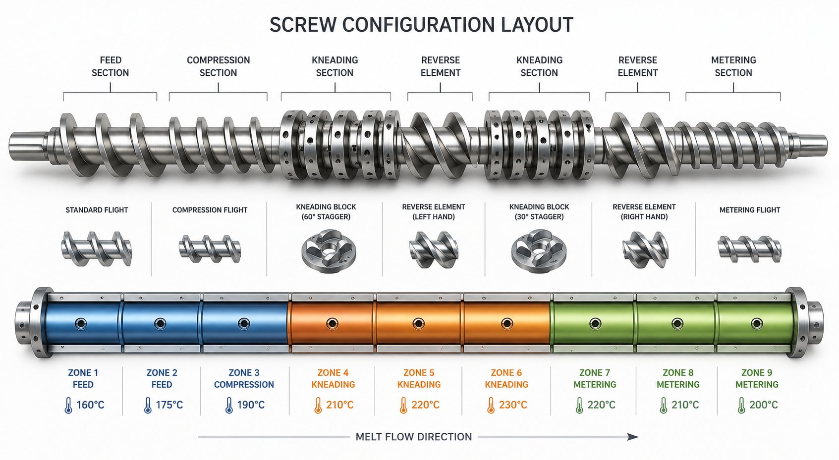
Picture a horizontal bar stretching across a page, segmented into dozens of labeled blocks, with temperature values running underneath and annotation markers popping up above. That's the screw configuration chart — the single most information-dense document in twin screw extrusion engineering. It's the blueprint that tells you exactly which modular element sits where, what barrel temperature surrounds it, and how far along the L/D axis each processing transition occurs. If the full machine schematic is a map, the screw profile chart is the turn-by-turn directions.
Surprisingly, most technical resources skip over this format entirely. They'll describe individual element types or list barrel zone functions, but they rarely explain how the chart itself is structured — or how to read it as a unified design document. Let's fix that.
Anatomy of a Screw Configuration Chart
The layout follows a consistent convention across twin screw extruders from virtually every manufacturer. Here's what you'll see:
A horizontal bar spans the full width of the chart, representing the screw shaft from feed end (left) to discharge end (right). This bar is divided into individual segments, each drawn roughly to scale, with every modular screw element labeled using its element code — the same alphanumeric notation covered earlier (SE 30/30 R, KBW 45/5/30 R, SE 20/20 L, and so on). You can literally count elements from left to right and reconstruct the entire physical screw assembly from the chart alone.
Directly below the screw bar, a parallel row displays barrel zone numbers with their corresponding set temperatures. Zone 1 might show "water cool only," Zone 2 could read 160°C, Zone 3 might jump to 200°C, and so on through to the final zone near the die. Each zone boundary aligns vertically with the screw elements it surrounds, so you can immediately see which elements operate at which temperature — a detail that's critical when diagnosing issues like premature melting in the feed section or insufficient plastication in mid-barrel zones.
Above or alongside the screw bar, annotations flag the positions of side feeder injection points, atmospheric and vacuum vent openings, and pressure measurement locations. Some charts also mark the melt temperature probe position and the die adapter connection point. These overlays transform the chart from a simple parts list into a complete process map: you see not just what elements are installed, but where material enters, where volatiles escape, and where critical measurements are taken.
Running along the horizontal axis beneath everything, you'll find L/D ratio markings. These tell you how far along the screw's total processing length each element sits. On a 40:1 L/D machine with a 40 mm screw diameter, for example, each barrel zone spanning 4D covers 160 mm of screw length — and the L/D tick marks let you reference any position as a ratio rather than an absolute distance. This standardization is what allows engineers to compare screw profiles across different machine sizes. A kneading block starting at L/D 10 on a 27 mm lab extruder and a 92 mm production machine occupies the same proportional position, even though the physical dimensions differ dramatically.
Designing a Screw Profile for Specific Processes
The configuration chart isn't just a record of what's already built. It's the primary design tool engineers use to plan new screw profiles from scratch — and the communication document they hand to suppliers when ordering replacement elements or specifying configurations for a compounding twin screw extruder.
The design process follows the same left-to-right logic as the chart itself. Imagine you're configuring a profile for a glass-fiber-reinforced polypropylene compound. You'd start by sketching the element sequence step by step:
- Feed zone (L/D 0–8): Open-pitch conveying elements like SK 40/40 R fill the first several positions. Their wide pitch and deep channels pull pellets away from the feed throat quickly, keeping the screws partially filled to avoid torque spikes.
- Plastication zone (L/D 8–16): Forward kneading blocks step in — perhaps starting with KB 30° elements for gentle initial softening, then transitioning to KB 60° or KB 90° blocks for aggressive melting. As NC State Extension's screw profile design guide emphasizes, an ideal screw profile will efficiently pump the material, break agglomerates, homogenize and melt the material, and develop appropriate melt temperature and pressure at the die.
- Melt seal before venting (L/D 16–18): A reverse element — something like SE 20/20 L — creates the backpressure barrier that ensures the downstream vent zone remains partially filled for effective devolatilization.
- Vacuum vent zone (L/D 18–22): Wide-pitch conveying elements return here, keeping the channel only partially filled so maximum melt surface area is exposed to the vacuum port above.
- Side feeder and downstream mixing (L/D 22–30): After the vent, a side feeder introduces glass fibers into the already-molten polymer. Gentle distributive mixing elements — toothed mixers (Z-type) or narrow-disc kneading blocks — blend the fibers without excessive breakage.
- Metering and discharge (L/D 30–40): Tight-pitch conveying elements build the final pressure needed to push melt through the die head or into a pelletizer.
Each element choice gets recorded on the chart with its exact code, and the barrel zone temperatures below are set to match. The result is a document that any technician can use to assemble the screw, any operator can reference during production, and any procurement team can use to reorder specific elements by code. For screw extruders used in granulation, recycling, or multi-component compounding, the chart becomes even more layered — sometimes showing two or three side feeder positions and multiple vent zones stacked along a 48:1 or 52:1 L/D layout.
Key Design Parameters Derived from the Schematic
Beyond the element-by-element detail, the configuration chart encodes — or allows you to derive — several high-level design parameters that define the machine's capability envelope. You'll often find these summarized in a specifications box on the schematic, but even when they're not explicitly stated, you can extract them from the chart itself:
- L/D ratio: The total processing length divided by the nominal screw diameter. Read directly from the horizontal axis markings. A longer L/D (e.g., 48:1 or 52:1) means more barrel zones and more room for complex element sequences — typical of compounding twin screw extruder layouts. Shorter ratios (32:1 or 36:1) suit simpler processes with fewer functional zones.
- Number of barrel zones: Count the individually numbered and temperature-controlled barrel segments shown below the screw bar. Most industrial twin screw extruders use 8 to 13 zones, with each zone spanning roughly 4D in length.
- Free volume: The total open channel volume available inside the barrel for material to occupy. While not drawn explicitly, free volume is a direct function of the screw element geometry — specifically the channel depth and flight width of each element. Deeper-channel conveying elements (like undercut UC elements) increase free volume, which is critical when processing low-bulk-density powders or highly filled formulations.
- Do/Di ratio (outer-to-inner screw diameter): This ratio — where Do is the outer diameter (screw tip) and Di is the inner diameter (screw root or shaft) — determines the balance between available processing volume and mechanical shaft strength. A higher Do/Di ratio (e.g., 1.66 or 1.80) provides deeper channels and greater free volume but reduces the shaft's torque-carrying capacity. A lower ratio (e.g., 1.45 or 1.55) yields a thicker, stronger shaft at the expense of channel depth. You'll typically find this value noted in the schematic's specification header or derive it from the cross-sectional view.
- Specific torque density: Expressed in Nm/cm³, this parameter reflects how much torque the gearbox can deliver relative to the screw's volumetric capacity. Higher values enable processing of tougher, more viscous, or more highly filled materials at meaningful throughput rates.
- Number and position of functional zones: By scanning the chart from left to right and noting where element types change — from conveying to kneading, kneading to reverse, reverse to venting — you can count the distinct functional zones the designer created. Each transition represents an intentional shift in what happens to the material at that L/D position.
These parameters don't exist in isolation. They interact with each other to define the processing window the machine can handle. A screw extruder granulator line running recycled HDPE at high throughput, for instance, demands a combination of high L/D (for adequate devolatilization residence time), high Do/Di (for maximum free volume to handle variable feedstock), and high specific torque (to manage the viscosity swings inherent in post-consumer resin). All of those requirements show up — directly or indirectly — on the configuration chart.
Reading these parameters from the schematic is where static documentation starts turning into operational insight. The barrel zone temperatures written beneath the screw bar, the vent positions marked above it, and the element codes along the shaft — they all connect to real process settings that an operator dials in on the machine's control panel every shift.
Translating the Schematic into Process Parameters on a Twin-Screw Extruder Machine
A schematic pinned to the workshop wall is only as useful as the operator who can connect its zones, annotations, and element codes to the numbers on the control panel. Every barrel zone boundary, every vent marking, and every side feeder symbol corresponds to a real setpoint, a real feed stream, or a real pressure reading that someone has to get right during production. Here's how each part of the drawing maps to the dials, screens, and sensors you'll actually touch.
Mapping Barrel Zones to Temperature Profiles
Each numbered barrel zone on the schematic has its own independent temperature controller on the machine. Zone 1 — the feed section — is typically set to water cooling only, or kept deliberately low (80-120°C for most thermoplastics), to prevent pellets from softening prematurely and bridging in the feed throat. Moving rightward on the drawing, temperatures ramp upward through the melting and kneading zones. You might see Zone 3 at 180°C, Zone 5 at 220°C, and Zone 8 holding at 240°C on a polypropylene compounding line.
The schematic's zone boundaries tell you exactly where each independent heating and cooling circuit begins and ends. This matters because adjacent zones can run at significantly different setpoints — a 40°C jump between Zone 4 and Zone 5 is common when the kneading block section demands rapid energy input. On a laboratory twin screw extruder with only 6 or 8 zones, each temperature transition carries even more weight because there are fewer segments to create a gradual ramp. Toward the die, temperatures often plateau or even decrease slightly. Lowering the final zone by 10-15°C can reduce melt temperature at discharge, which helps control degradation in heat-sensitive formulations — a principle that Technovel's process research confirms through direct experimental measurement of melt temperature responses to barrel setpoint changes.
Screw Speed, Feed Rate, and Throughput Connections
The schematic's L/D ratio and screw element arrangement don't just describe the machine — they constrain the operational window an operator works within. Screw RPM is the single most influential variable affecting shear rate and melt temperature. Experimental data from Technovel demonstrates that raising screw speed at constant throughput increases melt temperature while decreasing discharge pressure — higher shear heats the material, which drops its viscosity and reduces flow resistance at the die.
Feed rate has to match the conveying capacity defined by the screw profile's open-pitch elements in the feed zone. Overfeeding a double screw extruder machine beyond what those elements can pull forward causes torque spikes, material backup, and potential gearbox damage. Underfeeding leaves the screws too empty, reducing the shear stress available for mixing. The ratio of throughput to screw speed (Q/N) captures this balance and serves as a practical guideline — changing it shifts the fill state inside every channel, which in turn alters residence time, specific energy input, and mixing quality simultaneously.
Vacuum vent zones marked on the schematic also impose specific operational requirements. The pressure level at each vent — typically -0.06 to -0.09 MPa for standard devolatilization — must be maintained to prevent vent flooding, a condition where melt rises into the vent stack because the upstream melt seal (that reverse element on the schematic) isn't generating enough backpressure at the current feed rate.
Translating Vent and Side Feeder Positions to Process Steps
Every vent port on the schematic represents a devolatilization step in the real process. Atmospheric vents release entrained air and light volatiles — these are typically positioned shortly after the feed zone or immediately upstream of a side feeder. Vacuum vents handle the heavier work: removing residual moisture, unreacted monomers, or solvent from the polymer melt before it reaches the die. Leistritz's twin screw engineering report highlights that devolatilization efficiency depends heavily on melt surface renewal — partially filled screw channels under the vent create rolling melt pools that continuously expose fresh surfaces to the vacuum, improving mass transfer rates.
Side feeder positions on the schematic indicate exactly where downstream additives — glass fibers, mineral fillers, carbon black, or liquid additives — enter the melt stream. Operators must synchronize the feeder's dosing rate with the screw profile's conveying capacity at that barrel position. If the twin-screw extruder machine's screw elements at the side feeder location lack sufficient free volume to accept the incoming material, the additive backs up in the side stuffer and never incorporates properly. The schematic flags this risk: look at the element codes flanking each side feeder port. Wide-pitch conveying elements at that position signal adequate intake capacity, while tight-pitch elements would indicate a bottleneck.
Connecting schematic zones to their operational counterparts reveals the logic behind the drawing — but it also exposes the places where misinterpretation leads to real processing failures. Certain schematic-reading errors are remarkably common, even among experienced technicians, and they carry consequences that show up as scrap rates, quality deviations, and unplanned downtime.
Common Mistakes When Interpreting Double Screw Extruder Schematics
Even engineers with years of hands-on extrusion experience make reading errors that cascade into costly processing decisions. A misidentified element on a twinscrew profile chart can mean ordering the wrong replacement part, setting up a screw configuration that starves a vent zone, or specifying a mixing section that shreds heat-sensitive additives instead of gently blending them. The schematic itself is precise — the mistakes happen in how people interpret it.
Here are the five most common errors, along with practical guidance for avoiding each one.
Misreading Conveying Direction and Screw Rotation
This is the mistake that catches newcomers most often — and occasionally trips up veterans working with unfamiliar OEM documentation. On a twin screw extruder schematic, forward and reverse conveying elements can look nearly identical at first glance. Both show helical flight geometry. Both occupy similar positions along the barrel. The critical difference is a single letter in the element code: "R" for right-hand (forward) versus "L" for left-hand (reverse).
Confusing the two has serious consequences. A reverse element like SE 20/20 L doesn't move material toward the die — it pushes melt backward, creating a pressure seal. Mistaking it for a forward conveying element leads to the assumption that material flows freely through that zone, when in reality the designer placed it there specifically to create a full-channel melt dam. The fix is straightforward: always check both the element code suffix and the rotation direction arrows at the drive end. On a co-rotating machine, "R" elements convey forward and "L" elements convey backward. If the schematic includes cross-sectional views, you'll notice the flight helix angle reverses between the two types — a visual cue that confirms the code.
Confusing Kneading Block Stagger Angles
Imagine looking at a screw profile layout and seeing three kneading block sections in the melting zone. Are those 30-degree blocks for gentle distributive mixing, or 60-degree blocks delivering aggressive shear? On a printed schematic, the visual difference between stagger angles can be subtle — especially on small-scale drawings for a benchtop twin screw extruder where element representations are compressed.
The danger here is misassessing the shear intensity at a given zone. A reader who mistakes 30-degree blocks for 90-degree ones might conclude the melting section is far more aggressive than the designer intended. Conversely, misidentifying 90-degree neutral blocks as 45-degree forward blocks leads to the false assumption that material is still being conveyed through that section, when the zero-conveyance characteristic of 90-degree blocks means melt is actually dwelling in place and absorbing maximum energy.
The authoritative reference is always the notation on the screw profile chart — the alphanumeric code that explicitly states the stagger angle (e.g., KBW 45/5/30 R versus KBW 90/5/30). As NC State Extension's screw design reference explains, the first number in a kneading block code represents the angular displacement of one disc relative to the next — not the visual angle you perceive in the drawing. Trust the number, not the picture.
Overlooking Venting Zone Requirements and Free Volume
This error is less about misreading a symbol and more about missing a critical relationship between elements. Effective devolatilization at a vacuum vent requires two conditions simultaneously: a melt seal upstream to prevent vacuum from pulling through the barrel, and partially filled screw channels beneath the vent opening so melt surface area is maximized for volatile removal.
If you examine a schematic and see a vacuum vent port with no reverse element or restrictive kneading block positioned upstream, that design is likely flawed. Without a melt seal, the vacuum system pulls air straight through open screw channels instead of extracting volatiles from the melt surface. Adam Dreiblatt of CPM Century Extrusion identifies this as a root cause of vent flooding — a chronic problem where melt rises into the vent opening because the upstream seal elements aren't creating sufficient pressure to contain the melt pool below the vent zone.
Students and junior engineers frequently overlook this upstream-downstream dependency. They focus on the vent port symbol itself and neglect the elements flanking it. The schematic tells the whole story — but only if you read the elements before and after the vent as a coordinated system, not as isolated components.
Beyond these three detailed errors, two additional misinterpretations deserve a spot on your watch list:
- Confusing single-screw and twin-screw schematics: A cylindrical barrel cross-section indicates a single-screw extruder. A figure-8 bore indicates a double screw extruder. These are fundamentally different machine geometries — misreading one as the other leads to incorrect assumptions about intermeshing behavior, self-wiping capability, and residence time distribution. Always check the cross-sectional view before interpreting element functions.
- Ignoring Do/Di ratio implications on free volume: Two schematics can show identical element codes and barrel zone counts, yet deliver very different processing behavior if their outer-to-inner diameter ratios differ. A higher Do/Di ratio means deeper channels and greater free volume per element — critical when scaling from a benchtop twin screw extruder to a production-scale machine. Overlooking this parameter causes engineers to assume that a screw profile proven on a small machine will perform identically on a larger one, when the volumetric geometry may have shifted significantly.
Each of these errors shares a common thread: they arise from reading individual symbols in isolation rather than interpreting the schematic as an integrated system. The element codes, rotation arrows, vent positions, and cross-sectional views work together to describe a coherent processing strategy. Misread one piece, and the rest of the picture shifts out of alignment — which is exactly why schematic literacy matters most when the stakes are highest: selecting and sourcing the right screw and barrel components for a specific extrusion application.
Matching Screw and Barrel Configurations to Your Extrusion Process
A schematic only becomes valuable when it drives a real decision — specifying a new screw configuration, sourcing barrel segments for a different resin, or reconfiguring a line for an entirely new product. The same reading skills that help you decode rotation arrows and kneading block codes also guide you toward choosing the right hardware for your specific application. And here's what makes that connection practical: different extrusion processes produce dramatically different schematics. A plastics compounding line and a PVC pipe extrusion line don't just use different temperature profiles — they use different machine configurations, different L/D ratios, and different element sequences from feed to die.
Understanding those differences is the bridge between schematic literacy and confident equipment specification.
How Schematics Vary by Application
When you compare twin screw extruder schematics across industries, patterns emerge quickly. A compounding extruder schematic for glass-filled nylon looks nothing like a pharmaceutical hot-melt extrusion profile, even though both use co-rotating parallel machines. The table below captures how key schematic features shift across the most common application categories:
| Application Type | Typical Configuration | L/D Range | Key Schematic Features |
|---|---|---|---|
| Plastics compounding (filled/reinforced) | Co-rotating parallel | 40:1 to 52:1 | Multiple kneading block zones; side feeder for filler addition; vacuum vent for devolatilization; reverse elements creating 2-3 melt seals |
| Plastics recycling and pelletizing | Co-rotating parallel | 36:1 to 48:1 | Extended devolatilization section with dual vacuum vents; screen changer or melt filter before die; wide-pitch feed elements to handle variable bulk density |
| PVC pipe and profile extrusion | Counter-rotating conical or parallel | 17:1 to 26:1 (conical); 22:1 to 36:1 (parallel) | Shorter overall length; fewer kneading zones; tapered barrel on conical designs; gentle mixing elements to prevent thermal degradation |
| Sheet and film extrusion | Co-rotating parallel or single-screw with twin-screw compounder upstream | 32:1 to 44:1 | Emphasis on melt homogeneity; flat die adapter at discharge; melt pump symbol between extruder and die on some schematics |
| Masterbatch and color concentrate | Co-rotating parallel | 40:1 to 48:1 | Intensive dispersive kneading zones (wide-disc 90° blocks); multiple downstream mixing sections; high specific torque notation |
| Pharmaceutical and food extrusion | Co-rotating parallel | 25:1 to 40:1 | Shorter L/D; precisely placed kneading zones; narrow residence time distribution; no aggressive reverse elements; lower barrel temperatures throughout |
Notice the contrast. A plastic twin screw extruder schematic for compounding might stretch across 12 or 13 barrel zones with three separate kneading sections, two side feeders, and a vacuum vent — all packed into a 48:1 L/D layout. A conical twin screw extruder schematic for PVC pipe production, by comparison, might show just 5 or 6 zones across a compact 22:1 L/D design, relying on the tapered geometry itself to generate compression and mixing rather than stacking kneading blocks along the profile.
Recycling lines present their own schematic signature. Post-consumer resin varies wildly in bulk density, moisture content, and contamination level, so these schematics typically feature extended vent sections — sometimes two vacuum vents in sequence — and oversized feed zone elements to handle inconsistent feedstock. The screen changer drawn between the last barrel zone and the die head is another telltale marker: it's rarely seen on virgin compounding schematics but is nearly universal on recycling lines.
For twin screw extruder manufacturers serving multiple industries, these application-specific schematic patterns are the starting point for every machine specification conversation. An engineer who can walk into that conversation already knowing which L/D ratio, which element sequence, and which venting configuration their process demands is an engineer who gets the right machine faster — and avoids costly mid-project redesigns.
Selecting the Right Screw and Barrel for Your Extrusion Line
Reading the schematic is the diagnostic skill. Sourcing the right components is the action step that follows. Every modular screw element code on your configuration chart — every SE 30/30 R, every KBW 45/5/30 R, every reverse element creating a melt seal — corresponds to a physical part that needs to be manufactured to precise dimensional and metallurgical specifications. And when elements wear, when you reconfigure for a new resin, or when you scale up from a lab profile to production, you need a supplier who understands the full context behind those codes.
That context goes deeper than part numbers. The right barrel segment for a compounding extruder processing 40% glass-filled PA66 requires bimetallic construction with high-chromium or tungsten carbide liners to resist abrasive wear — a material decision that the schematic's filler notation implicitly demands. A conical barrel set for PVC pipe extrusion needs nickel-alloy liner chemistry to withstand the hydrochloric acid that PVC releases at processing temperatures. These aren't generic purchasing decisions. They're engineering decisions driven by what the schematic tells you about the process environment inside each barrel zone.
For engineering and procurement teams looking to connect their schematic knowledge to actual component sourcing, NANHAIYA's Plastic Extruder Machine and Screw Barrel Support provides a practical starting point. Their platform connects extrusion manufacturers, recycling plants, and technical teams with screw barrel components across the full range of plastic processing applications — pipe, profile, sheet, pelletizing, recycling, and general compounding lines. Whether you're replacing worn kneading elements on a twin-screw extruder manufacturer's machine or specifying a complete barrel set for a new recycling line, working with a supplier who understands diverse extrusion applications ensures that element geometry, metallurgy, and dimensional tolerances match your actual process design — not just a generic catalog listing.
The sourcing principle is simple: your schematic defines what you need, and your supplier should be able to read that schematic as fluently as you do. If a component vendor can't discuss the difference between a dispersive kneading block at L/D 12 and a distributive toothed mixer at L/D 28 — or why your recycling line's vacuum vent section demands different barrel metallurgy than your virgin compounding line — they're selling parts, not solutions.
From Schematic Literacy to Process Mastery
Every section of this guide has built toward a single capability: the ability to look at a twin screw extruder schematic and understand not just what it shows, but what it means for the material flowing through the machine, the parameters set on the control panel, and the components bolted onto the shafts and barrel housings.
That capability compounds over time. Engineers who read schematics fluently optimize existing lines faster — they identify which kneading zone to modify when dispersion quality drops, which barrel zone temperature to adjust when melt temperature drifts, and which reverse element to reposition when vent flooding occurs. They specify new equipment with precision, communicating exact element sequences and barrel configurations to twin-screw extruder manufacturers instead of relying on generic application recommendations. And they evaluate component suppliers with sharper criteria, asking the metallurgical and geometric questions that separate commodity parts from engineered solutions.
The schematic is where every extrusion conversation starts. Whether you're standing in front of a production-scale compounding extruder or a benchtop research unit, the drawing on the wall — or the configuration chart on your screen — encodes everything the machine was designed to do. Your job is to read it, interpret it, and act on it. That's how schematic literacy becomes process mastery.
Twin Screw Extruder Schematic FAQs
1. What is a twin screw extruder schematic?
A twin screw extruder schematic is a scaled engineering drawing that maps every functional zone, modular component, and material flow path of a twin screw extruder. It uses standardized symbols, annotations, and cross-sectional views to show how the drive system, segmented barrel zones, screw elements, venting ports, side feeders, and die head connect from the motor end to the discharge end. Engineers, operators, and procurement teams rely on it for machine assembly, screw element ordering, troubleshooting, and process optimization.
2. How do you read screw element notation on a twin screw extruder schematic?
Screw element notation encodes geometry in a compact alphanumeric format. For conveying elements, the code follows a pitch/length/direction pattern — for example, SE 30/30 R means a 30 mm pitch, 30 mm length, and right-hand (forward) rotation. Kneading blocks add stagger angle and disc count — KBW 45/5/30 R indicates a 45-degree stagger angle, 5 discs, 30 mm total length, and forward conveyance. The suffix R denotes forward movement while L denotes reverse. Notation systems vary slightly between manufacturers like Coperion, Leistritz, and others, but the underlying logic remains consistent across the industry.
3. What is the difference between co-rotating and counter-rotating twin screw extruder schematics?
On a co-rotating schematic, both rotation arrows at the drive end point in the same direction, the barrel shows a symmetrical figure-8 bore, and the screw profile typically features multiple kneading block zones for intensive mixing. Co-rotating machines dominate compounding and reactive extrusion with L/D ratios of 32:1 to 52:1. Counter-rotating schematics show arrows pointing in opposite directions. Parallel counter-rotating designs maintain constant screw diameter, while conical counter-rotating schematics display a visibly narrowing barrel from feed to die. Counter-rotating machines suit PVC processing and heat-sensitive materials with shorter L/D ratios.
4. Why is a reverse element needed before a vacuum vent on a twin screw extruder schematic?
A reverse element upstream of a vacuum vent creates a melt seal — a fully filled barrel zone that acts as a pressure barrier. This seal prevents vacuum from pulling air backward through open screw channels and ensures the vent zone's screw channels remain only partially filled. Partially filled channels expose maximum melt surface area to the vacuum, dramatically improving removal of moisture, residual monomers, and volatiles. Without this melt seal element on the schematic, the devolatilization design is likely flawed and the line risks vent flooding during operation.
5. Where can I source replacement screw and barrel components that match my twin screw extruder schematic?
Once you can read your schematic's element codes and barrel zone specifications, you need a supplier who understands the full engineering context — not just part numbers. NANHAIYA's Plastic Extruder Machine and Screw Barrel Support (nhyscrews.com) connects extrusion manufacturers, recycling plants, and technical teams with screw barrel components for diverse plastic processing applications including pipe, profile, sheet, pelletizing, and recycling lines. A knowledgeable supplier will match element geometry, metallurgy, and dimensional tolerances to your actual process design rather than offering generic catalog listings.
Written by
Nanhaiya Technical Team
Zhoushan Nanhaiya Plastic Machinery Co., Ltd.
The Nanhaiya technical team supports screw and barrel manufacturing projects through application review, technical communication, custom manufacturing coordination, and production and quality control.
Discuss Your Application
Related Articles
More insights on screw barrel technology and plastics processing.

What Nobody Tells You About Screw Barrel For Plastic Machine Design
Oct 10, 2026
Learn how screw barrel for plastic machine design affects melt quality, throughput, and wear life. Covers geometry, resin matching, troubleshooting, and sourcing.
Read Article
Single Screw Extruder for Sheet: Stop Guessing, Start Specifying
Oct 9, 2026
Learn how to specify a single screw extruder for sheet production. Covers screw geometry, resin-specific processing, troubleshooting, and maintenance best practices.
Read Article
PE Pipe Extruder Machine: What Datasheets Won't Tell You
Oct 9, 2026
Learn how a PE pipe extruder machine works, key specs explained, material grade selection, maintenance tips, and buyer guidance beyond the datasheet.
Read ArticleLooking for something else?
Search by material, symptom or product and jump straight to the relevant page.
These are navigation suggestions based on keyword matching — not a quotation, not a delivery commitment, and not a substitute for engineering review. Final specification is confirmed by our engineers against your drawings and processed material.
Need help with screw barrel selection?
Share your machine model, processed material and application. Our team can help with pricing and technical support.