

What Is a Twin Screw Extruder and Why It Matters for Plastic Processing
Imagine feeding raw polymer pellets into one end of a machine and pulling out perfectly compounded, melt-homogenized material from the other. That is exactly what a twin screw extruder does — and how well it does it depends entirely on configuration choices most operators never revisit after installation.
What Is a Twin Screw Extruder
A twin screw extruder is a plastic processing machine that uses two intermeshing or non-intermeshing screws rotating inside a heated barrel to convey, melt, mix, and shape thermoplastic materials into a uniform melt for compounding, pelletizing, or direct product extrusion.
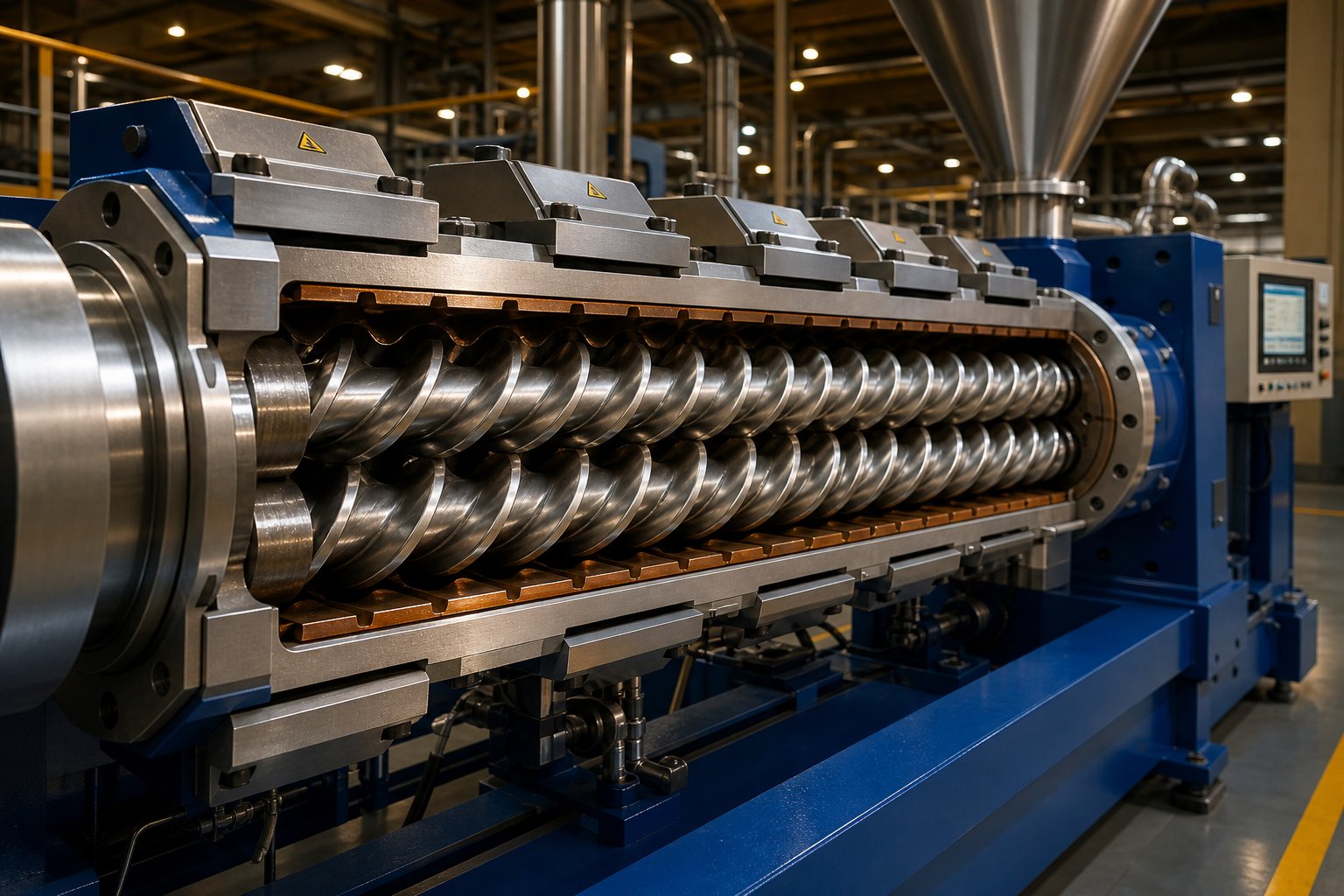
At its core, every twin-screw extruder relies on four primary components working in concert: the screws themselves, a segmented heated barrel, a high-torque drive system, and a shaping die at the discharge end. Raw material — pellets, powder, or regrind — enters through a feed hopper, and the rotating twin screw flights push it forward. As the material advances, barrel heaters and intense shear forces generated between the screws gradually melt and plasticize it. Specialized screw elements along the way knead, disperse, and homogenize the melt before it exits through the die.
You'll notice this sounds somewhat similar to a single screw extruder at first glance. The critical difference lies in what happens between those two screws.
Why Twin Screw Extruders Dominate Plastic Compounding
Single screw systems depend almost entirely on barrel friction to convey material. A twin screw extruder, by contrast, uses the positive displacement created by intermeshing flights to move material forward with far greater control. This design difference unlocks several advantages that matter on the plant floor:
- Superior dispersive and distributive mixing — intermeshing screws generate high shear forces that break down additive agglomerates and distribute fillers uniformly throughout the polymer matrix.
- Precise residence time control — throughput can be adjusted independently of screw speed, preventing thermal degradation of heat-sensitive resins.
- Self-wiping action — in intermeshing designs, each screw flight sweeps the surface of its counterpart, eliminating stagnant material that would otherwise degrade and contaminate the product.
These capabilities explain why twin screw extruder plastic processing dominates compounding operations for filled systems, masterbatch production, engineering plastics, and reactive modification. A single screw machine can melt and push material through a die, but it simply cannot match the mixing intensity or process flexibility a twin screw delivers.
This article goes deeper than a general overview. Every section ahead focuses specifically on plastics — from configuration choices and screw element design to material-specific recommendations and real-world troubleshooting — because generic guidance is exactly how the wrong setup ends up silently eroding your output quality.
Co-Rotating vs Counter-Rotating Twin Screw Extruder Configurations Compared
Knowing what a twin screw extruder does is one thing. Knowing which configuration to specify for your particular plastic application — that is where the real performance gains or losses hide. The rotation direction of the twin screws fundamentally changes how material moves, melts, and mixes inside the barrel. Pick the wrong setup, and you may never realize the machine is underperforming until quality complaints start stacking up.
Co-Rotating Intermeshing Twin Screw Extruders
In a co rotating twin screw extruder, both screws turn in the same direction — typically with a fully intermeshing geometry. This creates a distinctive flow pattern: material is forcibly handed off from one screw flight to the next at the intermeshing zone, tracing a figure-eight path along the barrel length. The result is a powerful self-wiping action that continuously clears each screw surface, leaving virtually no dead zones where resin could stagnate and degrade.
Why does that matter in practice? Three reasons stand out:
- Narrow residence time distribution — every polymer particle spends roughly the same amount of time inside the barrel. Heat-sensitive plastics like certain polyolefin blends and engineering resins benefit enormously from this consistency.
- Intense dispersive and distributive mixing — high shear fields develop between the screws and between screw and barrel, making it possible to break apart filler agglomerates and distribute additives uniformly.
- Fast material and color changeovers — because the self-wiping geometry prevents material buildup, purging between production runs takes far less time and waste resin.
These characteristics explain why the co-rotating intermeshing parallel design is the dominant platform for twin screw extrusion in compounding, masterbatch production, polymer alloying, and reactive extrusion. When you need maximum mixing flexibility paired with modular screw element configurations, this is the layout most engineers reach for.
Counter-Rotating Twin Screw Extruder Configurations
Flip one screw's rotation direction, and the machine behaves very differently. In a counter-rotating twin screw extruder, the two screws turn in opposite directions. Material drawn into the intermeshing zone gets compressed rather than handed off, producing what engineers call a calendering effect — repeated compressive and elongational deformation similar to what happens between calender rolls.
This calendering action disperses additives under relatively gentle conditions and keeps shear-induced heat generation low. For materials like rigid PVC, which has a notoriously narrow processing window and decomposes quickly under excessive shear, that gentle touch is not optional — it is essential. Counter-rotating twin screw extruders handle PVC pipe, sheet, and profile extrusion precisely because they can maintain stable melt conditions at lower screw speeds and higher fill levels.
Counter-rotating designs come in two distinct interaction variants:
- Intermeshing counter-rotating — tight screw engagement creates positive conveying and strong pressure buildup, ideal for direct extrusion applications that need consistent die pressure (pipes, profiles, window frames).
- Non-intermeshing counter-rotating — screws operate independently without mechanical contact, producing the lowest shear forces of any twin screw configuration. This variant offers the highest free volume and excels at devolatilization processes requiring removal of solvents or high levels of volatiles.
The table below maps the key performance differences between co rotating and counter rotating twin screw extruder configurations side by side, giving you a quick reference for matching machine type to application requirements.
| Parameter | Co-Rotating Intermeshing | Counter-Rotating Intermeshing | Counter-Rotating Non-Intermeshing |
|---|---|---|---|
| Mixing Intensity | High (dispersive + distributive) | Moderate (calendering-based dispersive) | Low (gentle distributive) |
| Pressure Generation | Moderate | High | Low |
| Self-Wiping Capability | Excellent | Good | Poor |
| Shear Level | High (adjustable via screw design) | Low to moderate | Very low |
| Typical Screw Speed | 200 - 900+ RPM | 30 - 150 RPM | 50 - 300 RPM |
| Typical Plastic Applications | Compounding, masterbatch, reactive extrusion, polymer alloys | PVC pipe/profile, WPC, rigid extrusion | High-volatiles devolatilization, specialty polymers |
| Throughput Range | Highest | Moderate | Lower (process-limited) |
Intermeshing vs Non-Intermeshing Designs
Rotation direction grabs most of the attention, but the degree of screw engagement deserves equal consideration. In intermeshing twin screw extruders, the flight of one screw reaches into the channel of the other. This tight mechanical interaction drives three critical outcomes: positive material conveying independent of barrel friction, high shear for dispersive mixing, and continuous self-cleaning that prevents degradation-causing stagnation.
Non-intermeshing designs sacrifice that tight engagement on purpose. The screws rotate without touching, each processing material within its own channel. Shear stress drops dramatically, residence time increases, and the free volume inside the barrel rises. This makes non-intermeshing configurations a niche choice — but a valuable one — for applications where aggressive mixing would damage the polymer or where extended dwell time is needed for chemical reactions or deep volatile removal.
For the vast majority of plastic compounding operations, intermeshing designs win out. The superior mixing efficiency, positive conveying behavior, and self-cleaning action align directly with the demands of filled compounds, color concentrates, and engineering resin formulations. Non-intermeshing finds its place mainly in specialty chemical processing and pharmaceutical hot-melt extrusion, where the priority shifts from throughput to extremely gentle material handling.
Configuration choices do not stop at rotation direction and engagement level, though. The physical geometry of the screws — whether they run parallel or taper from feed to discharge — introduces another layer of decision-making that directly affects compression behavior, feed intake, and application fit.
Conical vs Parallel Twin Screw Extruder Designs Explained
Rotation direction and screw engagement tell you how material gets mixed. Screw geometry — whether the barrels run parallel or taper from feed to discharge — tells you how material gets compressed, conveyed, and pressurized on its way to the die. Choose the wrong geometry for your resin and application, and you'll fight feed problems, pressure limitations, or unnecessary process inflexibility for the entire life of the machine.
Parallel Twin Screw Extruder Design and Applications
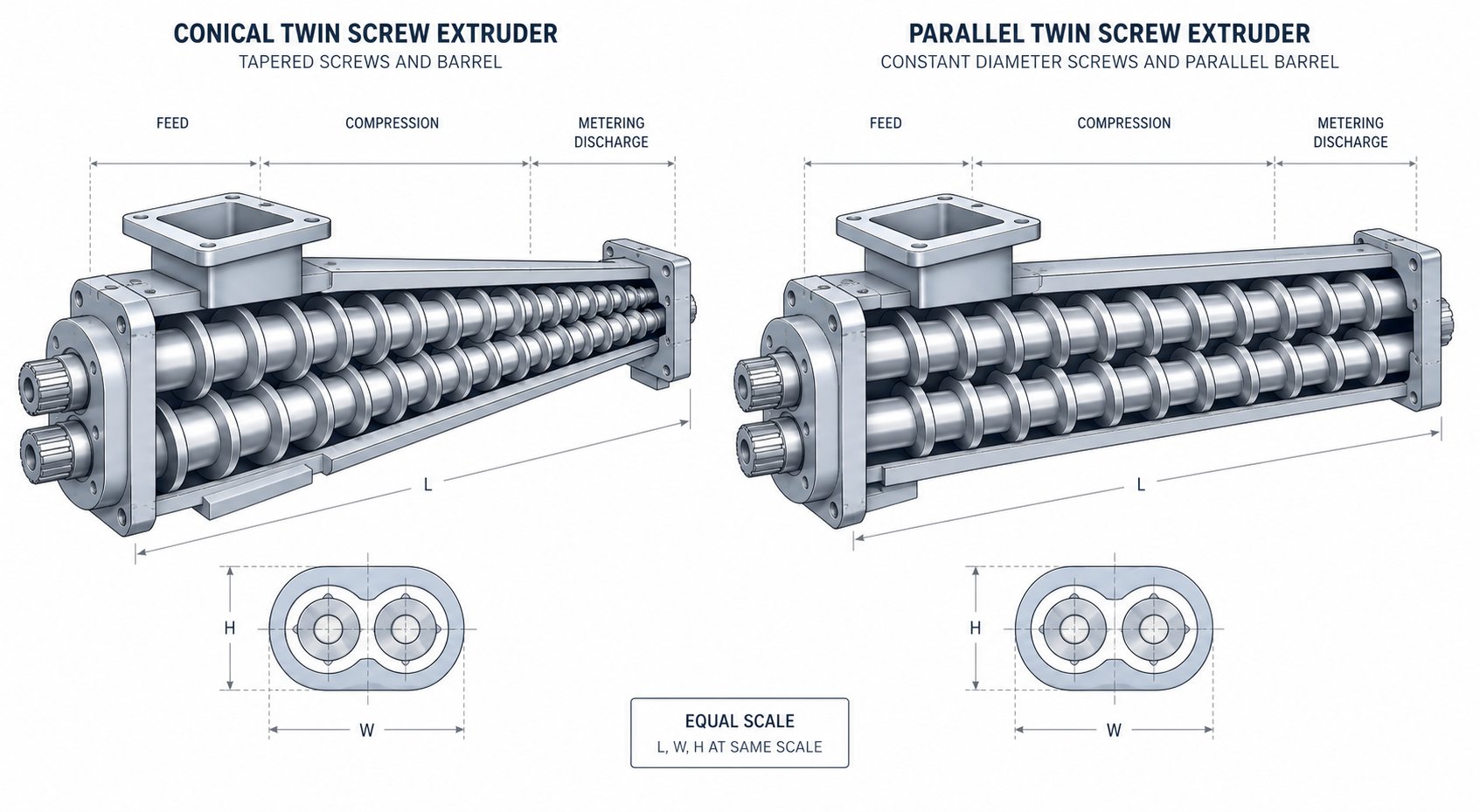
A parallel twin screw extruder features two screws with a constant diameter running at a fixed center distance along the entire barrel length. Picture two identical cylinders side by side — the screw root diameter, flight outer diameter, and channel depth remain uniform from feed throat to discharge. This consistent geometry is what makes the modular design concept possible.
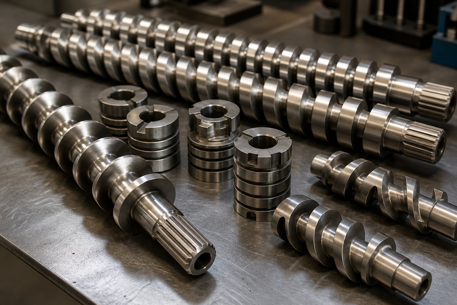
Why does modularity matter so much? Because on a parallel platform, the screw shaft is essentially a splined backbone onto which individual screw elements — conveying flights, kneading blocks, mixing discs, reverse elements — slide and lock into place like building blocks. Need to move a kneading zone further downstream? Swap the element positions. Want to add a vent port? Remove a barrel section and reconfigure the screw to match. This flexibility is unmatched in plastic compounding, where formulations change frequently and a single extruder twin screw line may process dozens of different recipes over its service life.
Parallel designs also support higher L/D ratios — commonly 32:1 to 48:1, and sometimes beyond 52:1 for demanding applications. A longer processing length translates directly into more barrel zones for heating, cooling, feeding, venting, and mixing. For complex compounding tasks involving engineering plastics with glass fiber reinforcement, high-fill mineral compounds, or color masterbatch requiring multiple additive injection points, that extra length is not a luxury. It is a process necessity.
Key strengths of the parallel configuration include:
- Fully modular screw and barrel construction — individual elements can be swapped, rearranged, or replaced without changing the entire screw.
- High throughput potential — screw speeds can reach 600 to 900+ RPM on modern gearbox platforms, driving substantial output rates.
- Scalability across sizes — parallel extruders are available from small laboratory-scale machines (screw diameters under 20 mm) to production-scale units exceeding 300 mm diameter.
- Process versatility — the same double screw extruder machine can handle polymer alloying one week and filled compound production the next, simply by reconfiguring the screw profile.
Conical Twin Screw Extruder Geometry and Benefits
A conical twin screw extruder takes a fundamentally different approach. Instead of maintaining constant screw diameter, the screws taper from a larger diameter at the feed end to a smaller diameter at the discharge end. Imagine two cones set at a slight angle to each other, their axes converging toward the die. As material travels from the wide feed opening toward the narrower discharge, the decreasing channel volume creates a natural, progressive compression — no special screw elements or geometry tricks required.
This built-in compression ratio solves a very specific problem that plagues certain plastic processing applications: feeding low-bulk-density powders. PVC dry-blend, for example, enters the extruder as a fluffy powder with a bulk density far below its melt density. The oversized feed opening of a conical design swallows that powder efficiently, while the tapering geometry steadily compacts and densifies the material as it moves toward the die. Trying to force that same powder through a constant-diameter parallel barrel often leads to inconsistent feed intake and starved screw zones.
Conical designs deliver several additional advantages for direct extrusion applications:
- Strong melt pressure generation — the progressive volume reduction builds substantial die pressure without relying on aggressive screw speeds, which keeps shear heat low.
- Compact machine footprint — because the converging axes allow the screws to be shorter overall, conical extruders occupy less floor space than parallel machines with equivalent output for PVC applications.
- Robust torque transmission — the larger screw root diameter at the feed end accommodates bigger bearings and a stronger drive shaft, enabling high torque at low RPM.
The trade-off is clear: conical screws are typically manufactured as one-piece units. You cannot rearrange elements or swap kneading blocks the way you can on a parallel platform. The screw profile is fixed at the design stage, so the machine is purpose-built for a defined set of materials and products. For PVC pipe, rigid profile, window frame extrusion, and similar dedicated production lines, this locked-in design is perfectly acceptable — even preferred — because the process rarely changes.
Choosing Between Conical and Parallel Geometries
So when does each geometry earn its place on your plant floor? The decision usually comes down to three questions: What material are you processing? How often does the formulation change? And does the extruder feed a pelletizing system or a direct shaping die?
If you're running a dedicated PVC line producing pipe or window profiles month after month, a conical twin screw extruder delivers exactly the compression, pressure, and gentle processing that PVC demands — at a lower capital cost than a parallel equivalent. But if your operation compounds multiple polymer types, switches between filled and unfilled formulations, or needs the flexibility of a double screw extruder machine that can adapt to new business opportunities, the parallel design's modularity and higher L/D ratios make it the stronger long-term investment.
The comparison table below maps both geometries against the parameters that matter most when specifying an extruder twin screw system for a specific plastic processing application.
| Parameter | Conical Twin Screw Extruder | Parallel Twin Screw Extruder |
|---|---|---|
| Typical L/D Ratio | 12:1 to 22:1 (based on average diameter) | 32:1 to 52:1+ |
| Compression Behavior | Natural progressive compression via tapering geometry | Achieved through screw element selection and pitch changes |
| Screw Modularity | One-piece screws; fixed profile | Fully segmented; elements interchangeable on splined shafts |
| Throughput Flexibility | Lower; optimized for defined output range | Higher; adjustable via screw speed, feed rate, and element configuration |
| Feed Intake of Low-Bulk-Density Powders | Excellent (large feed opening) | Requires optimized feed zone design |
| Die Pressure Generation | High (inherent to geometry) | Moderate (supplemented by melt pump when needed) |
| Best-Fit Applications | PVC dry-blend processing, rigid profiles, pipe extrusion, WPC | Compounding, masterbatch, filled systems, engineering plastics, reactive extrusion |
| Typical Screw Speed Range | 15 - 50 RPM | 200 - 900+ RPM |
| Capital Cost (Comparable Output) | Lower for PVC-focused applications | Higher, but greater long-term versatility |
Geometry determines what a machine can do at a fundamental level — but within both conical and parallel designs, the individual screw elements you install along the barrel length are what ultimately control melting, mixing, venting, and pressure buildup. That element-level configuration is precisely where most twin screw performance issues originate, and where the biggest gains in product quality and throughput are hiding.
Screw Element Design and How Configuration Shapes Processing Outcomes
You could install the perfect extruder — right rotation direction, right geometry, right barrel length — and still produce inconsistent, degraded material if the elements along that screw shaft are arranged incorrectly. The extruder screw configuration is where compounding performance is truly won or lost. Each individual element type generates a specific combination of conveying force, shear intensity, and back-pressure, and the sequence in which you stack them determines how your polymer melts, mixes, vents, and pressurizes on the way to the die.
Think of it like building a recipe from unit operations. Every element is an instruction the material must follow — and getting the order wrong creates process chaos that shows up as gels, color streaks, surging output, or thermal degradation.
Conveying Elements and Feed Zone Design
Conveying elements are the workhorses of material transport. They look like traditional helical screw flights and serve one primary job: move material forward. Their pitch — the axial distance between consecutive flights — directly controls how aggressively they push resin downstream.
Larger pitch conveying elements grab material quickly and move it fast, supporting higher throughput but generating less compression. Smaller pitch elements slow things down, increase fill level, and build pressure. Process engineers use this pitch variation strategically along the barrel length:
- Feed zone — deep-flight, large-pitch elements efficiently grip incoming pellets or powder and pull them into the barrel. The goal here is maximizing solids intake without creating a choke point.
- Transition zones — gradually decreasing pitch supports controlled melting by increasing material contact with the heated barrel wall.
- Metering zone near the die — tighter pitch builds stable pressure for consistent output and smooth surface finish on the extrudate.
Conveying elements generate relatively low shear on their own. They are not mixing elements — relying on them alone for additive dispersion would leave visible defects in the product. Their real contribution lies in controlling fill level and pressure development, which directly influences how the downstream kneading and mixing sections perform.
Kneading Blocks for Dispersive and Distributive Mixing
If conveying elements are the workhorses, kneading blocks are the precision instruments. These elements consist of multiple disc-shaped lobes stacked on the screw shaft, each offset from its neighbor by a defined stagger angle. That angular offset is one of the most powerful tuning levers available in screw extrusion — small changes in angle produce dramatically different mixing behaviors.
Here is how stagger angle shapes what the plastic extrusion screw does to your material:
- 30° stagger (low angle) — the block still conveys material forward while splitting and recombining the melt stream. This promotes distributive mixing, spreading colorants, additives, and minor components uniformly throughout the polymer matrix without applying excessive stress. Ideal for polymer blends and masterbatch where uniform distribution matters more than particle size reduction.
- 60° stagger (steep angle) — forward conveying drops significantly. Residence time in the kneading zone increases, and shear intensifies. This is a transition point between distributive and dispersive behavior.
- 90° stagger (neutral) — the block has virtually zero net conveying capacity. Material oscillates back and forth across the discs, experiencing intense shear stress and pressure fluctuations. This is dispersive mixing territory — exactly what you need to fracture hard agglomerates of carbon black, silica, or mineral fillers in highly filled compounds.
Disc width adds another layer of control. Narrower kneading discs create more frequent flow interruptions along a shorter axial distance, generating sharper local pressure gradients that boost dispersive action. Wider discs produce smoother flow and gentler mixing. As NC State Extension research notes, the arrangement of kneading elements significantly affects mixing efficiency — forward kneading blocks are less aggressive, neutral blocks increase residence time and energy input, and reverse kneading blocks create maximum restriction and shear.
The trade-off is always the same: more aggressive kneading means higher melt temperature and greater torque demand. Overdo it with 90° blocks on a heat-sensitive resin, and you will degrade the polymer faster than you disperse the filler.
Reverse Elements and Mixing Restrictors
Reverse-flight elements — sometimes called left-handed or re-conveying elements — do exactly what the name implies: they push material backward against the overall forward flow. Sounds counterproductive, right? In practice, these elements are essential for two critical functions in any screw extruder configuration.
First, reverse elements create a melt seal. By forcing material upstream, they build a fully filled, pressurized plug of polymer at a specific barrel location. This seal is what makes vacuum venting possible — without it, the vacuum pump would simply pull air through an open melt stream instead of extracting trapped moisture and volatiles. Engineers position reverse elements just upstream of vent ports to ensure that seal holds during operation.
Second, reverse elements extend local residence time. Material cannot simply slide past a reverse zone; it gets held up, reprocessed, and pushed back into upstream mixing sections before eventually overcoming the restriction. This controlled holdup is valuable when a reaction needs time to complete or when stubborn agglomerates need repeated passes through a kneading zone.
Alongside reverse flights, tooth-type mixing elements offer a gentler alternative for homogenization. These gear-like elements repeatedly split and recombine the melt without imposing the high shear stress of kneading blocks. They are particularly useful for final-stage distributive mixing — ensuring composition uniformity right before the die without driving up melt temperature in the last barrel zones.
Building a Screw Configuration for Plastic Compounding
Every compounding screw profile follows a logical sequence of process zones, each populated with element types matched to the task at hand. While no single configuration works for all materials — as NC State's extrusion research emphasizes, screw design is a blend of art and science because every polymer behaves differently under heat and shear — a general-purpose compounding layout follows a recognizable pattern.
Here is a typical screw configuration sequence from feed to discharge for a standard compounding application:
- Feed zone — large-pitch conveying elements with deep flights to efficiently intake pellets, powder, or regrind and move them downstream under starve-fed conditions.
- Melting/plasticizing zone — conveying elements with progressively decreasing pitch, transitioning into forward kneading blocks that initiate melting through a combination of barrel heat transfer and mechanical shear.
- Primary mixing zone — a combination of kneading blocks at increasing stagger angles (30° through 60° or 90°) to achieve the required balance of distributive and dispersive mixing for the specific formulation.
- Melt seal before vent port — a short reverse-flight element or reverse kneading block creating back-pressure and a fully filled zone to seal the melt ahead of the atmospheric or vacuum vent.
- Vent/devolatilization zone — large-pitch conveying elements that drop pressure and reduce fill level, exposing maximum melt surface area for moisture, monomer, or volatile release.
- Secondary mixing zone — distributive mixing elements or tooth-type mixers for final homogenization without excessive temperature rise.
- Metering/pressurization zone — tight-pitch conveying elements that rebuild stable pressure for consistent flow through the screen changer, diverter valve, and die.
This sequence is a starting framework, not a fixed rule. A glass-fiber-reinforced nylon compound would use milder kneading after the fiber side-feed point to avoid breaking fiber length. A heavily filled calcium carbonate masterbatch would front-load aggressive dispersive blocks. A volatile-rich recycled feedstock might need two separate vent zones, each preceded by its own reverse element seal.
The key insight is this: the same extruder hardware — identical barrel, identical drive, identical die — produces vastly different results depending solely on how these screw elements are sequenced. Getting the configuration right for your specific plastic and process is the single highest-leverage decision in the entire extrusion line. And getting it wrong? That is exactly how output quality erodes silently, batch after batch, while operators chase symptoms instead of root causes.
Matching Plastic Types to Twin Screw Extruder Configurations
A perfectly configured screw profile means nothing if it is paired with the wrong machine type for the resin you are running. Every plastic brings its own processing personality — melt viscosity, thermal stability window, shear sensitivity, moisture behavior, and filler compatibility all dictate which twin screw compounding extruder configuration will deliver consistent quality versus one that quietly degrades material batch after batch. The gap between "it runs" and "it runs right" almost always traces back to this material-to-machine match.
Commodity Plastics and Twin Screw Processing
Polypropylene and polyethylene are the workhorses of compounding twin screw extruder operations worldwide. PP compounding typically involves blending the base resin with mineral fillers like talc or calcium carbonate, glass fiber reinforcement, impact modifiers, UV stabilizers, or color concentrates. Co-rotating parallel machines handle these tasks exceptionally well because PP tolerates moderate to high shear and benefits from the intense dispersive mixing that breaks apart filler agglomerates. Screw speeds commonly range from 300 to 600 RPM depending on filler loading, with throughput scaling alongside screw diameter.
PE processing follows a similar pattern for masterbatch production and filled compound applications. A polymer extruder running PE-based color concentrates at 40-60% pigment loading needs aggressive kneading sections to disperse tightly packed pigment particles, and co-rotating designs deliver that shear without excessive residence time. PE blending operations for film or sheet applications also benefit from the modular screw flexibility that parallel machines provide.
PVC is the exception that proves the rule. With a processing window as narrow as 165-185 degrees Celsius and a tendency to release corrosive hydrochloric acid when overheated, PVC punishes high-shear configurations ruthlessly. That is why PVC pipe and profile extrusion almost universally relies on counter-rotating twin screw extruders — either conical designs for dry-blend powder feeding or parallel counter-rotating setups for specific sheet and fitting applications. Screw speeds stay low, typically 15 to 50 RPM on conical machines, keeping shear-generated heat well within PVC's safe zone.
Engineering and Specialty Plastics on Twin Screw Extruders
Engineering resins raise the stakes considerably. PA (nylon) compounding with glass fiber reinforcement is one of the most demanding applications any compounding extruder faces. The glass fiber must be side-fed after the polymer is fully melted to prevent excessive fiber breakage, and the downstream screw elements need to distribute fibers uniformly without shortening them below the critical length needed for mechanical performance. Co-rotating parallel machines with L/D ratios of 40:1 or higher provide the barrel length required for staged feeding, effective mixing, and adequate venting.
PET processing introduces moisture sensitivity as the dominant challenge. Even small amounts of residual moisture cause hydrolytic degradation that destroys molecular weight and mechanical properties. Any polyester extruder line handling PET compounds must include aggressive pre-drying — typically to below 50 ppm moisture — combined with vacuum devolatilization zones on the extruder itself. Co-rotating configurations with dedicated vent ports and reverse-element melt seals are standard for PET compounding and direct sheet extrusion applications.
TPE and TPU compounds demand precise temperature control above everything else. These materials have relatively narrow melt processing ranges, and slight overheating causes surface defects, discoloration, or loss of elastomeric properties. The extruder for polymer systems like TPU benefits from co-rotating designs where screw speed and barrel temperatures can be independently fine-tuned zone by zone, with gentle distributive mixing elements replacing aggressive kneading blocks in the later barrel sections.
Highly filled mineral compounds — think 60-80% calcium carbonate in carrier resin — push torque demands to their limits. The sheer volume of abrasive filler increases screw and barrel wear dramatically while requiring high dispersive energy to wet every particle. High-torque co-rotating parallel extruders with wear-resistant screw and barrel metallurgy are the only practical choice for these formulations.
Material-to-Configuration Recommendation Matrix
The table below consolidates the material-specific guidance into a single reference that maps common plastic types to their recommended twin screw configurations and key process parameters. Bookmark this — it is the kind of quick-reference matrix that saves hours of trial-and-error on the plant floor.
| Plastic Type | Recommended Configuration | Typical Screw Speed Range | Key Processing Considerations | Primary Applications |
|---|---|---|---|---|
| PVC (rigid) | Counter-rotating, conical or parallel | 15 - 50 RPM | Narrow thermal window (165-185 deg C); shear sensitivity; corrosive decomposition products; low-bulk-density powder feeding | Pipe, window profiles, rigid sheet, fittings |
| PP (filled/reinforced) | Co-rotating, parallel | 300 - 600 RPM | Tolerates moderate shear; filler dispersion critical; vis-breaking possible for melt flow control | Automotive parts, appliance housings, filled pelletizing |
| PE (masterbatch/blends) | Co-rotating, parallel | 300 - 500 RPM | Good shear tolerance; high pigment loadings need dispersive kneading; crosslinking risk at excessive temperatures | Color masterbatch, film compounds, pipe compounds |
| PA (glass fiber reinforced) | Co-rotating, parallel (L/D 40:1+) | 200 - 500 RPM | Hygroscopic — requires pre-drying and vacuum venting; side feeding for fiber preservation; high barrel temperatures (240-280 deg C) | Structural parts, automotive, electrical connectors, pelletizing |
| PET | Co-rotating, parallel with vacuum venting | 200 - 400 RPM | Extremely moisture-sensitive; aggressive drying to below 50 ppm; devolatilization essential; IV loss risk under excessive shear | Sheet extrusion, fiber compounds, recycled pelletizing |
| TPE / TPU | Co-rotating, parallel | 150 - 400 RPM | Narrow melt window; precise zone-by-zone temperature control; gentle distributive mixing preferred in later zones | Soft-touch overmold compounds, tubing, film, pelletizing |
| Mineral-filled compounds (60-80% CaCO3, talc, BaSO4) | Co-rotating, parallel (high torque) | 200 - 500 RPM | Extreme torque demand; severe abrasive wear on screws and barrels; high dispersive energy for filler wetting; dust management at feed | Filler masterbatch, cost-reduction compounds, sheet |
Notice a pattern? Co-rotating parallel machines dominate the matrix for a reason — their modularity, speed range, and mixing versatility cover the broadest range of thermoplastic compounding demands. Counter-rotating designs earn their place specifically where gentle processing, natural compression, or low-shear conveying is non-negotiable, most notably PVC.
Selecting the right configuration for your resin gets the foundation right. But even within a correctly matched machine, two process capabilities — venting for volatile removal and reactive modification — separate baseline compounding from truly optimized twin screw extrusion. These capabilities rely on the same screw element principles covered earlier, yet they introduce their own set of design rules that deserve focused attention.
Venting Devolatilization and Reactive Extrusion Fundamentals
A screw configuration that melts, mixes, and pressurizes flawlessly still produces defective material if trapped moisture, residual monomers, or volatile contaminants remain locked inside the melt. Likewise, a machine that simply blends polymers without enabling chemical modification leaves significant value on the table. Venting and reactive extrusion are two capabilities that elevate a twin screw extruder from a mixing device into a precision processing platform — yet both are routinely overlooked during machine specification and screw design.
Atmospheric and Vacuum Venting in Twin Screw Extrusion
Why does venting matter? Because nearly every plastic compound carries some level of unwanted volatiles into the barrel. Moisture absorbed by hygroscopic resins like nylon and PET, trapped air pockets dragged in with powders and regrind, residual monomers left over from polymerization, and volatile organic compounds released during thermal processing — all of these contaminants cause bubbles, surface defects, reduced mechanical properties, and odor issues in the final product if they are not actively removed during the twin screw extrusion process.
Devolatilization is the mass-transfer process that strips these volatiles from the polymer melt. As Plastics Technology explains, it works by superheating the volatile component and then exposing the melt to a rapid decompression, driving the volatiles out of solution and into the vapor phase where they can be extracted. Twin-screw extruders excel at this because their screw elements can be configured to create alternating zones of high compression and sudden pressure release along the barrel length.
Two distinct venting approaches serve different severity levels of volatile contamination:
- Atmospheric venting — open ports in the barrel wall that allow volatiles to escape directly to atmosphere when the melt pressure drops to ambient at that location. These vents rely purely on the pressure differential between the melt stream and the surrounding air. They work well for initial moisture flash-off and light volatile release, and are typically positioned early in the barrel — shortly after the melting zone — where the bulk of surface moisture and trapped air needs to escape quickly.
- Vacuum venting — sealed barrel ports connected to vacuum pumps that actively pull volatiles from the melt surface at sub-atmospheric pressure. By lowering the partial pressure above the melt, vacuum venting drives diffusion of deeply trapped contaminants to the surface far more aggressively than atmospheric exposure alone. These vents are positioned downstream, after the polymer is fully melted and mixed, to achieve deep devolatilization of residual monomers, solvents, and trace VOCs.
Placement strategy follows a logical progression. Imagine you are processing a hygroscopic engineering resin that arrives with 0.15% moisture. An atmospheric vent positioned two to three barrel zones after the feed throat flashes off the majority of that surface moisture as the polymer first melts. Further downstream — past the primary mixing zone — a vacuum vent operating at 20 to 50 mbar absolute pulls out the remaining deeply embedded moisture and any volatile byproducts generated during high-temperature processing.
Here is the critical detail that makes or breaks vent performance: each vent port requires a fully sealed melt zone immediately upstream. Reverse screw elements or reverse kneading blocks positioned just before the vent create a pressurized plug of polymer that isolates the low-pressure vent zone from the rest of the barrel. Without this melt seal, vacuum simply pulls air through the screw flights from adjacent zones instead of extracting volatiles from the melt surface. As devolatilization expert Rob Jerman notes, changes in screw speed can alter the stability of these seals — increasing speed shortens the filled length behind both seals, making them more susceptible to failing, while decreasing speed risks backing polymer up into the vent port itself.
A practical rule of thumb reinforces why multiple vent stages matter: each properly designed vent can reduce volatile concentration by roughly an order of magnitude. A triple-vented machine, for example, can bring a feed stream containing several percent volatiles down below 0.1% residuals with consistent results. This makes multi-vent configurations essential for applications demanding ultra-low residual levels — food-contact packaging, medical-grade compounds, and automotive interior parts with strict VOC emission limits.
The following list summarizes key devolatilization applications where venting capability directly determines product quality:
- Moisture removal from hygroscopic resins such as PA (nylon) and PET to prevent hydrolytic degradation and molecular weight loss
- Residual monomer stripping from styrenics, acrylics, and other chain-polymerization plastics to meet regulatory and odor requirements
- Solvent removal during solution-based polymer processing and masterbatch production
- VOC reduction for automotive-grade compounds that must pass strict cabin air quality and fogging specifications
Reactive Extrusion on Twin Screw Platforms
Venting removes what you do not want in the melt. Reactive extrusion adds — or modifies — what you do want. This is where extruder technology crosses the boundary from mechanical processing into controlled chemistry, and twin-screw extruders turn out to be remarkably effective continuous chemical reactors.
The concept sounds ambitious: execute a chemical reaction inside a machine designed for melting and mixing plastic. But as reactive extrusion pioneer Costas Gogos explains, twin-screw extruders possess unique advantages for this role. They handle polymer particulate feeding and melting efficiently in very short processing times, carry out rapid laminar distributive mixing of high-viscosity melts so that reactants contact uniformly, and achieve good control of temperature and residence-time distribution — all prerequisites for completing reactions in short dwell times and producing a uniform product.
What kinds of chemical modifications happen inside a twin screw barrel? The most commercially significant include:
- Grafting reactions — attaching functional groups like maleic anhydride onto polyolefin backbones to create compatibilizers used in blending immiscible polymer pairs. PP-g-MAH and PE-g-MAH are produced in enormous volumes through reactive extrusion, and roughly 30% of all polymers sold are in the form of compatibilized immiscible blends that depend on these grafted products.
- Controlled degradation (vis-breaking) — peroxide-initiated chain scission of polypropylene to reduce molecular weight and narrow its distribution, producing "spinnable" PP grades with lower viscosity for fiber and nonwoven applications. This was one of the earliest organized reactive extrusion processes, dating back to the mid-1960s.
- Crosslinking — peroxide- or silane-initiated crosslinking of polyethylene for wire and cable insulation, where the extruder simultaneously melts, reacts, and shapes the product in a continuous operation.
- Chain extension — rebuilding molecular weight in recycled or degraded polymers using reactive additives, extending the useful life of post-consumer resin streams.
Co-rotating twin-screw extruders dominate reactive extrusion for a reason that ties directly back to their fundamental design strengths. The precise residence time control means every polymer chain experiences nearly identical thermal and chemical exposure — critical when you need uniform grafting or consistent molecular weight reduction across the entire output. The modular screw design allows engineers to position kneading blocks for intense initial mixing of reactants, followed by conveying zones that provide the dwell time for the reaction to proceed, followed by vent zones that strip off unreacted monomers or reaction byproducts.
Industry expert Bill Thiele highlights an important practical consideration: many graft reactions look much like conventional compounding from an equipment standpoint, making them accessible to compounders willing to add precision liquid injection and careful stoichiometric control to their existing lines. More complex reactive processes — polycondensation, polymerization of monomers — push toward longer L/D ratios (40:1 to 60:1 on co-rotating machines, or even 120:1 on counter-rotating non-intermeshing platforms) and demand specialized safety infrastructure for handling flammable or toxic reactants.
The intersection of reactive chemistry and extruder technology opens up a value chain that goes far beyond simple mixing. Compounders who master reactive extrusion gain the ability to create proprietary, performance-differentiated products — functionalized polymers, upgraded recyclates, specialty alloys — using the same twin screw platform they already operate for conventional compounding. That versatility is exactly why understanding venting and reactive capability is not optional knowledge. It is what separates a machine that merely melts plastic from a system that transforms it.
Of course, no twin screw extruder operates in isolation. The melt that exits the die — whether compounded, devolatilized, or reactively modified — must be cooled, cut, classified, and packaged by downstream equipment that matches the extruder's output capacity and product requirements. Getting that downstream integration wrong creates bottlenecks that choke the entire line.
Downstream Equipment and Integrated Extrusion Line Design
A twin screw extruder that melts, mixes, and devolatilizes perfectly still produces scrap if the pelletizer jams, the screen changer surges, or the cooling system cannot keep pace with throughput. Yet most equipment evaluations focus almost exclusively on the extruder itself — screw diameter, torque rating, L/D ratio — while treating everything after the die as an afterthought. That disconnect is where silent productivity losses hide. The extruder system only performs as well as its weakest downstream link, and overlooking pelletizing, filtration, or cooling capacity turns a well-specified machine into a bottlenecked line.
Pelletizing Systems for Twin Screw Extrusion Lines
The moment compounded melt exits the die, it needs to become something a customer can handle — uniform, free-flowing pellets ready for injection molding, film blowing, or further processing. Three pelletizing technologies dominate twin screw compounding operations, and each one suits a different combination of polymer type, throughput target, and pellet geometry requirement.
Strand pelletizing remains the most widely used approach in traditional compounding plants. The molten plastic exits through a multi-hole strand die as continuous spaghetti-like rods. These strands travel across a water bath trough to solidify, then get pulled into a rotary cutter that chops them into cylindrical pellets. The process is straightforward, easy to operate, and budget-friendly in terms of equipment cost. It works exceptionally well for materials with reliable melt strength — think glass-fiber-reinforced nylon, standard PP compounds, and color masterbatch — because the strands need enough structural integrity to survive the water bath traverse without snapping. However, as GSmach's pelletizing comparison notes, highly filled compounds with 70%+ mineral loading produce extremely brittle strands that break constantly during cooling, generating excessive scrap and production downtime.
Underwater pelletizing sits at the opposite end of the technology spectrum. Here, the cutting assembly — die face, hub, and blades — operates fully submerged in a pressurized tempered water chamber. The melt gets cut hot at the die face, and the surrounding water instantly quenches each pellet into a uniform, near-spherical shape. The water flow then transports pellets out of the cutting chamber, preventing sticking even with tacky elastomers like TPU and hot-melt adhesive compounds. Underwater systems handle the highest throughput ranges — 300 to 3,000+ kg/h — and produce the most consistent pellet geometry. The trade-off? Higher upfront capital, more complex startup and cleaning procedures, and longer changeover times between materials or colors. For a dedicated, high-volume production line running a single formulation, the investment pays for itself quickly. For small-batch operations switching recipes frequently, the operational overhead can outweigh the benefits.
Water-ring pelletizing occupies the middle ground. Like underwater systems, it cuts the melt hot at the die face. But instead of submerging the entire cutting assembly, a spinning ring of cooling water flows around the interior wall of the cutting chamber. Centrifugal force flings the hot-cut pellets into this water ring, where they partially solidify before being swept into a slurry line leading to a centrifugal dryer. Water-ring systems handle a practical throughput range of roughly 200 to 1,200 kg/h and produce round, smooth pellets without the capital cost or complexity of a full underwater setup. They excel with polyolefin-based materials — HDPE, LDPE, PP — and soft PVC recycling, where the screw extruder granulator output benefits from die-face cutting but does not demand the precision of a submerged system.
Choosing the wrong pelletizer for your material creates problems that look unrelated to the cutting system itself. Brittle strand breaks get blamed on the die. Deformed pellets get attributed to melt temperature issues. Moisture in the final product gets traced back to drying problems. In reality, the root cause is often a fundamental mismatch between the pelletizing technology and the polymer's melt behavior.
Screen Changers, Melt Pumps, and Cooling Systems
Between the extruder discharge and the pelletizer sits a series of auxiliary components that many buyers underestimate until they cause problems. Each one serves a distinct function — and skipping or under-specifying any of them ripples through the entire line.
Screen changers filter the melt stream by passing it through layers of woven wire mesh supported on a breaker plate. Their primary job is catching contaminants — gels, degraded fragments, metal particles, unmelted resin chunks — before they reach the die and create defects in the pellet or finished product. For recycling applications especially, where post-consumer feedstock carries metal fragments, paper fibers, and cross-contaminated polymer particles, adequate screen filtration is non-negotiable. As JF Extruder's filtration guide explains, the screen pack also contributes backpressure that helps stabilize the melt and improve uniformity — a clean screen adds modest resistance, while a contamination-loaded screen progressively increases pressure until it must be changed.
The critical consideration with screen changers is the pressure drop event during screen replacement. Removing a loaded screen and inserting a fresh one causes an abrupt pressure change that propagates to the die, creating a temporary segment of off-spec product. Manual slide-plate changers are simple and economical but require a line slowdown or stop for each change. Continuous screen changers use dual-station or hydraulically actuated designs that keep one filter position active while the other is serviced, minimizing pressure fluctuation. For high-contamination feedstocks — recycled regrind, heavily filled compounds — continuous changers reduce scrap significantly over time.
Melt pumps (gear pumps) address a different challenge: pressure stability at the die. Even with consistent screw speed and feed rate, minor fluctuations in melt viscosity, backpressure, and barrel temperature create small pressure waves that translate into dimensional variation in the extrudate. A melt pump installed between the extruder and the die isolates these fluctuations by delivering a volumetrically precise, pulsation-free melt stream. For profile extrusion and sheet lines where dimensional tolerances are tight, a melt pump transforms inconsistent output into repeatable precision. For standard pelletizing operations with more forgiving geometry requirements, a pump may not be necessary — but it is worth evaluating whenever dimensional consistency complaints arise.
Cooling systems solidify the product after the die and determine surface quality, crystallinity development, and dimensional accuracy. Water bath troughs are standard for strand cooling in compounding lines. Calibration tanks — vacuum-sealed cooling chambers — are essential for pipe and profile extrusion, where the extrudate must be dimensionally locked before it shrinks and warps. Air cooling conveyors serve applications where water contact is undesirable, such as moisture-sensitive resins or specialty elastomers. The cooling system's capacity must match the extruder's maximum output rate; an undersized cooling section becomes the line's bottleneck even if every upstream component is perfectly specified.
Designing an Integrated Extrusion System
Here is the fundamental point most equipment evaluations miss: a twin-screw extruder machine is not a standalone piece of equipment. It is the centerpiece of an integrated processing line where every component — from the gravimetric feeder at the inlet to the bagging station at the outlet — must be matched in capacity, control logic, and process timing. Specify a high-speed extruder but pair it with a low-capacity pelletizer, and the pelletizer dictates your actual throughput regardless of what the extruder nameplate says.
A complete plastic compounding line built around a twin-screw extruder machine typically includes the following essential downstream components:
- Screen changer — continuous or manual, matched to contamination level and product tolerance
- Diverter valve — enables purging and off-spec material diversion during startup, shutdown, or recipe transitions without contaminating the pelletizing system
- Strand die or underwater pelletizer head — selected based on polymer type, throughput target, and pellet geometry requirements
- Cooling system — water bath trough for strand lines, tempered water loop for underwater pelletizers, or air cooling conveyors for moisture-sensitive products
- Centrifugal dryer or dewatering screen — removes surface moisture from pellets before packaging
- Classifier or vibrating screen — separates oversized pellets, fines, and agglomerates to ensure uniform pellet size distribution
- Bagging, boxing, or bulk packaging system — the final step before product reaches the customer
Control integration ties it all together. Modern compounding lines use centralized PLC systems that synchronize extruder screw speed, gravimetric feeder output, pelletizer cutter speed, and cooling parameters in real time. When the feeder detects a drop in throughput, the control system adjusts screw speed and pelletizer timing automatically — preventing the surging and pellet deformation that plague lines with independent, unlinked controls.
One detail deserves special emphasis: screw and barrel specifications must align with downstream capacity for the line to perform optimally over its service life. A screw profile designed for 800 kg/h output paired with a strand pelletizer rated for only 500 kg/h forces the operator to under-run the extruder — wasting motor capacity, extending cycle times, and inflating cost per kilogram. Conversely, pushing the extruder beyond the cooling system's heat removal capacity produces poorly solidified, deformed pellets that fail quality checks. The extruder system design process should work backward from the target output rate, specifying each downstream component first and then confirming the extruder screw and barrel can deliver the required melt quality at that throughput.
Getting this system-level integration right is what separates a production line that hits nameplate capacity on day one from one that spends months in troubleshooting mode — chasing pellet quality issues, surging problems, and throughput shortfalls that trace back to a mismatched downstream component rather than the extruder itself. And nowhere is that integration challenge more demanding than in plastic recycling operations, where inconsistent feedstock quality, high contamination loads, and aggressive wear conditions test every component in the line simultaneously.
Twin Screw Extrusion in Plastic Recycling and Circular Economy
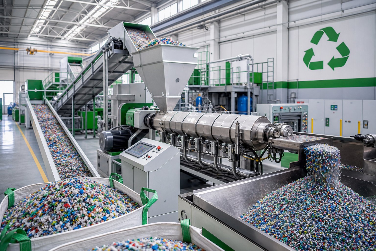
Inconsistent flake sizes, mystery contaminants, fluctuating moisture levels, and polymer chains already weakened by a previous life of heat and stress — recycled plastic feedstock throws every challenge at an extruder simultaneously. Single screw machines handled the job for decades when "recycling" meant little more than re-pelletizing clean factory regrind. But the circular economy demands something far more ambitious: transforming post-consumer waste streams into compounds that rival virgin resin performance. That leap in quality expectation is precisely why the plastic twin screw extruder has become the backbone of modern mechanical recycling plants.
Why Twin Screw Extruders Are Essential for Plastic Recycling
Picture a bale of post-consumer HDPE bottles arriving at a recycling facility. After washing and shredding, the resulting flake contains trace paper fibers from labels, adhesive residue, sand and grit from collection bins, occasional metal fragments, and a blend of polymer grades with different melt flow indices. Feeding this material into a single screw extruder produces a melt riddled with unmelted contaminants, trapped moisture pockets, and inconsistent viscosity — acceptable perhaps for a low-value drainage pipe, but nowhere close to the quality automotive or packaging customers expect.
A twin screw plastic extruder changes the equation fundamentally. As compounding leader Luis Roca of AIMPLAS explains, co-rotating twin screw extruders offer increased mixing capacity, higher productivity, greater degasification capacity, and the ability to work with a wider variety of materials compared to single screw systems. These advantages map directly onto the four core challenges recycled feedstock presents:
- Contaminant dispersion — the intense dispersive mixing generated by intermeshing kneading blocks breaks apart agglomerated contaminants and distributes them at a scale that minimizes their impact on mechanical properties. A single screw system simply cannot generate the shear fields needed to achieve this level of homogenization.
- Moisture and volatile removal — modular barrel construction allows multiple devolatilization zones, each preceded by reverse-element melt seals. Co-rotating machines can accommodate up to four vent ports — compared to one or none on a typical single screw recycling line — enabling aggressive extraction of moisture, residual solvents, VOCs, and odor-causing compounds that post-consumer waste carries in abundance.
- Mixed polymer stream blending — real-world recycled feedstock rarely arrives as a pure single-polymer stream. Multi-layer film scrap, mixed-color regrind, and cross-contaminated bales all require the kind of intensive melt blending that only a screw plastic extruder with configurable kneading and mixing elements can deliver effectively.
- Additive incorporation for property restoration — recycled material has already consumed a significant portion of its original stabilizer package. The twin screw platform allows inline addition of UV stabilizers, antioxidants, impact modifiers, compatibilizers, and reinforcing fillers to rebuild the mechanical and thermal performance that degradation has eroded.
This combination of capabilities explains a broader industry shift. Recyclers who once operated exclusively as format converters — turning flake into pellets — have evolved into compounders, producing specification-grade materials that compete directly with virgin resin in demanding applications. The co-rotating twin screw extruder made that transformation possible.
Recycling Applications and Process Considerations
The range of recycling scenarios a plastic extruder screw configuration must handle has expanded dramatically as circular economy mandates push recycled content into higher-value products. Each scenario brings its own processing demands:
Regrind pelletizing is the most straightforward application — clean factory scrap or well-sorted post-industrial waste gets re-melted, filtered, and pelletized for reuse. Even here, a twin screw setup outperforms single screw alternatives by delivering better melt homogenization and enabling screen changer integration for contaminant removal without excessive pressure fluctuation.
Compounding recycled content with virgin resin requires precise ratio control and thorough blending to ensure the final compound meets the same specification as a 100% virgin product. Gravimetric feeders meter recycled flake and virgin pellets into the barrel at controlled ratios, while the screw configuration's kneading zones ensure the two melt streams integrate seamlessly. This is where the modular screw design of co-rotating parallel machines proves invaluable — engineers can adjust mixing intensity to match whatever recycled content percentage the customer specifies, from 15% to 100%.
Upcycling through additive incorporation represents the highest-value recycling application. Impact modifiers restore toughness lost to chain degradation. Compatibilizers enable blending of otherwise immiscible polymer pairs found in mixed waste streams. Thermal and UV restabilization packages extend the service life of the recycled compound far beyond what the depleted original stabilizers could provide. Reinforcing fillers — glass fiber, talc, calcium carbonate — can even push recycled material performance above the virgin baseline. As Roca notes, co-rotating twin screw extruders can also adjust rheology through controlled degradation, tuning melt flow rate in PP and polyamide to match specific processing requirements downstream — a capability that gives recyclers direct control over their product's processability.
Challenging waste streams like multi-layer film scrap push the technology to its limits. Separating PE from PA or EVOH barrier layers in a multi-layer structure is often impractical mechanically. The alternative? Process the entire structure as a blend, using polymer compatibilizers injected via side feeders to create a stable, useful alloy from what would otherwise be landfill material. The blending capacity of co-rotating twin screws makes this feasible where no other extrusion platform can.
One critical operational reality deserves direct attention: screw and barrel wear accelerates significantly when processing recycled feedstock. Post-consumer material carries abrasive contaminants — sand, glass fragments, mineral residues, metal fines — that act like grinding paste between screw flights and barrel bore. Research from industry specialists confirms that a standard nitrided screw adequate for clean virgin polymer can wear out in a fraction of the expected service life when running contaminated recycled streams. The wear concentrates at flight crests and in high-pressure metering zones, progressively increasing screw-barrel clearance. As that clearance opens, mixing efficiency drops, output becomes unstable, and melt quality degrades — often so gradually that operators attribute the decline to feedstock variation rather than equipment wear.
This makes wear-resistant screw and barrel solutions not optional but essential for any recycling operation expecting consistent long-term performance. Bimetallic barrel liners with tungsten or chromium carbide alloys, hardfaced screw flights, and corrosion-resistant metallurgy for streams carrying PVC contamination (which generates hydrochloric acid on degradation) are baseline specifications for recycling lines — not upgrades. For recycling plants seeking screw and barrel components engineered for these demanding conditions, NANHAIYA's plastic extruder machine screw barrel support provides solutions specifically designed for recycling and pelletizing processing lines, backed by in-house manufacturing expertise that understands the wear patterns recycled feedstock creates.
The key twin screw advantages for plastic recycling consolidate into a clear value proposition:
- Superior melt homogenization — intensive mixing produces uniform compounds from inherently inconsistent recycled feedstock, closing the quality gap with virgin resin
- Effective devolatilization for moisture and odor removal — multiple vent zones strip trapped volatiles, residual solvents, and odor-causing compounds that post-consumer waste carries, enabling compliance with automotive VOC standards and food-contact migration limits
- Flexible feeding of flakes, regrind, and powder — the positive conveying action of intermeshing screws handles irregular particle shapes and low bulk densities that choke friction-dependent single screw feeders
- Ability to incorporate restabilization additives inline — side feeders and liquid injection ports allow simultaneous addition of stabilizers, compatibilizers, impact modifiers, and fillers during extrusion, eliminating the need for separate pre-compounding steps
The circular economy is not a future concept — it is a present-day operational reality reshaping how recycling plants specify equipment, configure screw profiles, and source wear components. Recycled content mandates across Europe, North America, and Asia are pushing post-consumer material into automotive interiors, consumer electronics housings, food packaging, and construction products that demand consistent, repeatable quality. The twin screw extruder is the technology platform making that transition possible. But even the best-configured recycling line eventually encounters process problems — surging output, black specks, melt temperature swings — that require systematic diagnosis to resolve before they erode product quality and customer confidence.
Troubleshooting Common Twin Screw Plastic Extrusion Problems
You have the right configuration, the right screw elements, and the right downstream equipment — yet something is off. Output surges unpredictably. Black specks appear in the pellets. Melt temperature drifts outside specification. These problems rarely announce themselves with a dramatic failure. Instead, they creep in gradually, eroding product quality and throughput so slowly that operators compensate with manual adjustments rather than investigating the root cause.
The reality on most plant floors? By the time a process engineer gets called in, the problem has been quietly compounding for weeks. This troubleshooting guide cuts through the symptom-chasing cycle and maps the most common twin screw extrusion failures directly to their causes and fixes.
Surging, Output Fluctuation, and Feed Issues
Output instability is the single most reported complaint on twin screw compounding lines, and it almost always traces back to one of three root causes.
Inconsistent feed rate tops the list. Hopper bridging — where material forms a stable arch above the feed throat and stops flowing — plagues powdery additives, fibrous fillers, and irregular regrind flakes. Low-bulk-density materials are especially vulnerable because they compact unevenly under gravity. When flow from the hopper stutters, the extruder alternates between starved and flooded zones, producing cyclic pressure swings at the die that show up as pellet weight variation or strand breakage.
Corrective actions are straightforward once you identify the source. Install vibrating hopper inserts or mechanical agitators to prevent bridging. For gravimetric feeders, recalibrate the load cell using the actual production material — not a test substitute — because bulk density differences skew feed accuracy significantly. As Kerke's troubleshooting guide recommends, verify that the feed throat cooling jacket maintains 20-40 degrees Celsius for most polymers, since overheating causes premature melting that sticks material to the feed screw and disrupts flow.
Worn screw flights are the second major cause. Conveying elements in the feed zone gradually lose flight height through abrasive contact with incoming material. As flight crests wear down, the positive displacement that drives material forward weakens. Output drops and becomes erratic — and the decline happens so gradually that operators typically compensate by increasing screw speed rather than measuring actual flight dimensions. This masking behavior burns extra energy and accelerates wear further downstream.
Improper screw speed relative to feed rate closes the triad. Running screw speed too high for the gravimetric feed rate starves the barrel, creating partially filled zones that produce inconsistent melt pressure. Running too low floods the feed section and spikes torque. The fix? Match screw RPM to feed rate so the extruder operates in a stable, partially filled (starve-fed) regime throughout the conveying zones. Most modern screw extruders provide real-time torque and pressure monitoring that makes this balance visible — use it.
Melt Quality Problems and Material Degradation
When the melt leaving the die contains visible defects, the screw configuration and thermal conditions inside the barrel deserve immediate scrutiny.
Unmelted particles (gels) in the extrudate point to insufficient melting energy. Either the kneading zone is too short, the stagger angles on kneading blocks are too mild for the resin being processed, or barrel temperatures in the melting zone are set too low. Check the screw configuration first — adding a kneading block or shifting from 30-degree to 60-degree stagger often resolves the issue without touching the temperature profile. If gels persist, verify that thermocouple readings are accurate by cross-checking with a handheld pyrometer, since faulty sensors frequently mislead operators into running barrels cooler than intended.
Thermal degradation presents the opposite problem — too much energy input. Yellowing, brittleness, odor, and reduced mechanical properties all signal that the polymer has spent too long at too high a temperature. Excessive residence time from over-aggressive reverse elements, unnecessarily high barrel zone temperatures, or screw speeds that generate shear heating beyond the resin's thermal stability window are the usual culprits. Reducing the number or length of reverse-flight elements, lowering downstream barrel temperatures by 10-15 degrees Celsius, and verifying that the extruder is not running at excessively low feed rates (which increases residence time) typically bring degradation under control.
Discoloration and black specks are among the most frustrating quality issues because they often appear intermittently and resist simple fixes. The root cause is almost always stagnant material degrading inside dead zones — and dead zones form where extruder screw and barrel surfaces have worn unevenly. As Plastics Technology explains, root wear creates pockets and hangup areas where material degrades, producing black specks and surging. Once clearance between the screw flight OD and barrel ID increases beyond acceptable limits, material leaks over the flight crests instead of being conveyed forward. This leaked polymer gets sheared repeatedly at elevated temperatures, carbonizes, and eventually breaks free into the melt stream as visible contamination.
The critical insight here: worn screws and barrels do not just reduce output. They actively degrade product quality by creating the stagnation zones and leakage flows that generate thermal degradation. By the time black specks are visible, the twin screw barrel clearance has likely expanded well beyond its original specification.
Screw and Barrel Wear Patterns
Wear is the silent killer of twin screw extrusion performance. It progresses slowly enough that operators adapt — increasing screw speed to compensate for lost conveying, raising temperatures to offset reduced shear heating, adjusting feed rates to stabilize pressure. Each compensation masks the real problem while introducing new ones: higher energy consumption, greater thermal stress on the polymer, and accelerated wear on the remaining good surfaces.
Abrasive fillers are the primary wear accelerator. Glass fiber, calcium carbonate, talc, barium sulfate, and recycled feedstock containing mineral contaminants all act as grinding media between screw flights and the barrel bore. Industry data shows that wear concentrates in high-pressure zones — the transition section and the final metering turns — because increased pressure and temperature amplify friction and abrasion. Larger filler particles with sharper corners inflict more damage than smaller, rounder ones, which is why glass-fiber-reinforced nylon compounds are notoriously hard on equipment compared to talc-filled PP.
Corrosive wear compounds the problem when processing materials that generate acidic byproducts. PVC decomposition releases hydrochloric acid. Certain flame retardants liberate corrosive gases at processing temperatures. These chemical attacks pit barrel and screw surfaces, roughening them and creating nucleation sites for further mechanical wear. The combination of abrasion plus corrosion — sometimes called corrosion-erosion — destroys standard nitrided steel surfaces far faster than either mechanism alone.
How do you know when twin screw and barrel wear has crossed the threshold from tolerable to production-threatening? A common rule of thumb flags a radial clearance four times the original tolerance as the cutoff for replacement, but this guideline must be adjusted for resin viscosity. High-viscosity polymers like HDPE tolerate greater clearance with less output loss because their resistance to leakage flow is naturally higher. Low-viscosity resins like PP and certain nylon grades lose output dramatically at the same clearance level because the thinner melt slips over worn flights far more easily.
The troubleshooting table below maps the most common twin screw extrusion problem symptoms to their likely causes and corrective actions — the kind of plant-floor quick reference that saves hours of diagnostic guesswork.
| Problem Symptom | Likely Cause | Corrective Action |
|---|---|---|
| Output surging (cyclic pressure swings at die) | Hopper bridging, inconsistent feeder calibration, or worn feed zone conveying elements | Install hopper agitator or vibrator; recalibrate gravimetric feeder with production material; measure feed zone flight dimensions and replace if worn beyond tolerance |
| Die buildup and drool | Degraded low-molecular-weight polymer fractions migrating to die lip; inadequate melt temperature; incompatible additive packages | Increase die zone temperature slightly; verify additive compatibility; clean die lips on a scheduled frequency; check for moisture in the feed causing volatile flashing at the die face |
| Black specks in extrudate | Stagnant material degrading in dead zones created by worn screw root or barrel bore; carbonized buildup on die surfaces | Pull and inspect screws — measure twin screw barrel clearance at multiple points; replace worn elements; clean or polish barrel bore; disassemble and clean die assembly |
| Inconsistent melt temperature (zone-to-zone drift) | Faulty thermocouples; failed or cracked heater bands; restricted cooling water flow from mineral buildup in barrel jackets | Cross-check thermocouple readings with handheld pyrometer; test heater continuity with multimeter; flush cooling water lines and verify flow rate meets manufacturer specification |
| Reduced throughput at constant screw speed | Increased screw-barrel clearance from wear allowing leakage flow; partially blocked screen pack raising backpressure; barrel temperature too low causing incomplete melting | Measure screw OD at transition and metering zones — replace worn elements or full screw assembly; change screen pack; verify barrel temperature profile matches resin requirements |
| Unmelted particles (gels) in extrudate | Insufficient kneading intensity; barrel temperatures too low in melting zone; worn kneading blocks with reduced shear capability | Add kneading block length or increase stagger angle (30 deg to 60 deg); raise melting zone barrel temperatures in 5-10 deg C increments; inspect and replace worn kneading elements |
| Yellowing or thermal degradation | Excessive residence time from over-restrictive reverse elements; barrel overtemperature; screw speed too low relative to feed rate | Shorten or remove reverse element sections; lower downstream barrel temperatures; increase feed rate to reduce dwell time in high-temperature zones |
One pattern emerges clearly from this table: worn extruder screw and barrel components appear as a contributing cause in the majority of these failure modes. Surging, black specks, reduced throughput, melt quality drift — all worsen as clearance between screw flight OD and barrel ID opens up. As screw wear expert Stephen Surley warns, screw wear is a gradual process that can go unnoticed until performance is greatly reduced, because operators adjust machine parameters to compensate for minor wear long before they pull the screw for inspection.
Proactive measurement beats reactive failure every time. Establish a baseline by recording screw flight OD dimensions and barrel bore ID measurements when components are new. Re-measure at scheduled maintenance intervals — quarterly for lines processing abrasive materials, semi-annually for clean polymer operations. Track the trend. When radial clearance doubles from new-condition values, plan your replacement. When it triples, order components immediately. Waiting until the four-times-original threshold means you have already been producing degraded material for months while paying higher energy costs and dealing with customer complaints you could have prevented.
Replacing worn screw and barrel components is not an expense — it is a maintenance strategy that protects product quality, throughput consistency, and energy efficiency simultaneously. The cost of a replacement twin screw and barrel set is a fraction of the accumulated losses from off-spec production, increased scrap, and customer returns that worn equipment silently generates.
Knowing when and why components fail is critical. But knowing how to select the right replacement — and the right machine — for your specific application closes the loop between troubleshooting a problem and preventing it from recurring.
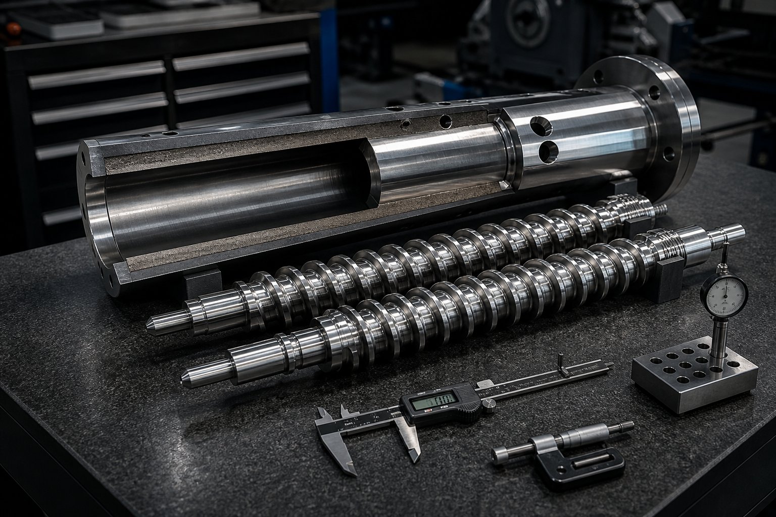
Selecting the Right Twin Screw Extruder and Screw Barrel Support
Troubleshooting fixes today's problems. Selection prevents tomorrow's. Every configuration decision, material match, and component specification discussed throughout this article converges on a single practical question: how do you evaluate and select a twin screw extruder — and its critical wear components — so the machine delivers consistent performance for years rather than months?
The answer is not a single spec sheet comparison. It is a structured decision framework that works backward from your application to the equipment that serves it best.
Key Selection Criteria for Twin Screw Extruder Equipment
Imagine you are standing on a trade show floor surrounded by twin screw extruder manufacturers, each promising higher torque, faster speeds, and better mixing. How do you cut through the noise? Start with the decision logic this article has built, step by step.
Match configuration to application. If your primary operation is PVC pipe or rigid profile extrusion, counter-rotating designs — conical or parallel — deliver the gentle shear, natural compression, and pressure stability PVC demands. For virtually everything else in plastic compounding — filled systems, masterbatch, engineering resin blends, reactive modification, recycling — co-rotating intermeshing parallel machines provide the mixing intensity, modularity, and throughput flexibility the work requires.
Select geometry based on material and process requirements. Conical twin screw extruders earn their place on dedicated PVC lines processing low-bulk-density dry-blend powders. Parallel designs dominate everywhere else because their segmented barrel and modular screw construction adapt to changing formulations, new product lines, and evolving customer specifications without replacing the entire machine.
Specify screw elements for the target mixing and venting profile. The screw configuration — conveying pitches, kneading block stagger angles, reverse element placement, vent port locations — determines product quality more directly than any other single factor. Ensure the twin-screw extruder manufacturer you evaluate offers genuine application engineering support for screw design, not just a catalog of standard profiles.
Plan for scale-up from the beginning. Many compounding projects start on a laboratory extruder — typically a 16 to 27 mm screw diameter machine — to validate formulations and establish baseline process parameters. A case study published by Dow demonstrates why this step matters: specific mechanical energy (SME) measured on a lab scale twin screw extruder served as the critical reference for scaling to pilot (40 mm) and production (92 mm) machines. Directly copying process conditions from a lab scale extruder to a production machine without matching SME resulted in unmolten pellets, phase separation, and complete process failure at the 92 mm scale — problems solved only after redesigning the screw profile and feeding configuration to restore the SME achieved on the smaller machine. The lesson is clear: invest in a lab scale twin screw extruder that is geometrically similar (same L/D ratio, same OD/ID ratio) to your target production platform, and use SME as the bridge between scales.
Beyond configuration, geometry, and scale-up strategy, several technical specifications separate machines that perform reliably from those that disappoint. Evaluate these factors systematically when comparing twin screw extruder for sale options from any supplier:
- L/D ratio — longer barrels (40:1 to 52:1+) provide more processing zones for complex compounding, multi-stage venting, and reactive extrusion; shorter ratios (32:1 to 36:1) suffice for simple blending and masterbatch
- Torque density — measured in Nm/cm3, this determines how much energy the drive can deliver per unit of free volume in the screw channel; higher torque density supports heavily filled compounds and high-viscosity engineering resins
- Maximum screw speed — modern co-rotating machines reach 600 to 1200+ RPM; ensure the gearbox and drive motor can sustain peak speed under full-load torque without overheating
- Barrel heating and cooling zones — more independently controlled zones enable finer temperature profiling; verify that cooling capacity matches the heat generation your formulation produces at target throughput
- Venting positions — confirm that barrel sections with vent ports are available at the locations your devolatilization requirements demand, with reverse-element melt seal capability upstream of each port
- Screw and barrel metallurgy — the single most consequential long-term cost factor, discussed in detail below
- Control system integration — centralized PLC with real-time torque, pressure, and temperature monitoring; compatibility with gravimetric feeders and downstream pelletizing equipment
- Spare parts availability and lead time — a high-performance machine loses its value advantage if replacement screw elements take 16 weeks to arrive
The twin screw extruder price on a purchase order is a starting point, not a final cost. Total cost of ownership — energy consumption per kilogram of output, maintenance intervals, screw and barrel replacement frequency, downtime for changeovers, and spare parts pricing — determines the real economic picture over a five- to ten-year equipment life. A lower-priced machine that consumes screws and barrels twice as fast costs more in the long run than a premium unit with superior wear component metallurgy.
The Role of Screw and Barrel Quality in Long-Term Performance
Every component in a twin screw extruder eventually wears. Gearbox bearings can be re-shimmed. Heater bands can be swapped in minutes. Thermocouples cost next to nothing. But the screws and barrel? They are the highest-wear, highest-impact, and highest-cost replacement components in the entire machine — and their quality directly determines how long your line runs at peak performance before output and product quality begin their silent decline.
As ENTEK's metallurgy specialists explain, the success or failure of any twin screw extruder application — especially when processing abrasive or corrosive materials — depends on the ability of the wear parts to perform under difficult processing conditions. Their experience tracks a decisive industry shift: from 70% nitrided tool steels a decade ago to 60% Hot Isostatic Pressed (HIP) alloys today, driven by customer demand for longer service life in increasingly aggressive applications.
Three metallurgical factors govern screw and barrel longevity:
- Abrasive wear resistance — determined by the hardness and carbide content of the alloy. HIP materials like CPM 9V and 10V contain high volumes of vanadium carbides that resist the grinding action of glass fiber, mineral fillers, and recycled feedstock contaminants far longer than conventional nitrided steels.
- Corrosion resistance — critical when processing PVC (hydrochloric acid release), halogenated flame retardants, or fluoropolymers. High-chromium tool steels provide cost-effective protection for moderate corrosion. Extreme cases — fluoropolymer processing, for example — may demand exotic nickel-based alloys like Inconel or Hastelloy, though these sacrifice abrasive wear resistance due to lower hardness.
- Dimensional precision and surface finish — tight tolerances between screw flight OD and barrel bore ID maintain the mixing efficiency, conveying capability, and self-wiping action that define twin screw performance. As clearances open from wear, leakage flow increases, mixing degrades, and stagnation zones form that produce the black specks and thermal degradation covered in the troubleshooting section.
Modern best practice favors bimetallic construction for both screws and barrels. ENTEK's approach — a tough, ductile core that resists torque overloads surrounded by a wear-resistant HIP outer layer — addresses the practical reality that solid HIP screws, while extremely hard, are brittle and prone to breakage when an extruder stalls or overfeeds. Similarly, barrels built with replaceable liners rather than one-piece construction reduce long-term cost of ownership significantly. The barrel body — with its expensive machined cooling passages, thermocouple wells, injection ports, and bolt flanges — gets reused indefinitely while only the worn liner insert gets replaced.
Here is the bottom line: sourcing screw and barrel components from suppliers with deep in-house manufacturing expertise and genuine knowledge of plastic processing requirements is not a procurement detail. It is a strategic decision that affects product quality, maintenance budgets, and line uptime for years. A supplier who understands the difference between a screw profile for glass-fiber-reinforced nylon and one for recycled HDPE — and who manufactures components with metallurgy matched to each application's wear profile — delivers value that extends far beyond the component price.
For extrusion manufacturers, recycling plants, and technical teams evaluating screw barrel suppliers, NANHAIYA's plastic extruder machine screw barrel support offers a practical resource worth exploring. Their in-house manufacturing capability covers screw and barrel solutions for pipe, profile, sheet, pelletizing, recycling, and general plastic processing lines — the full range of twin screw applications discussed throughout this article. Teams specifying replacement components or outfitting new lines can review technical specifications and connect with application support tailored to their specific processing demands.
The right twin screw extruder, configured with the right screw elements, paired with properly matched downstream equipment, and maintained with quality screw and barrel components — that is the formula that turns a capital investment into years of consistent, profitable production. Get any one piece wrong, and output erodes silently. Get them all right, and the machine pays for itself many times over.
Frequently Asked Questions About Twin Screw Extruder Plastic Processing
1. What is the difference between a co-rotating and counter-rotating twin screw extruder?
A co-rotating twin screw extruder has both screws turning in the same direction, producing a self-wiping figure-eight flow pattern ideal for high-intensity compounding, masterbatch, and reactive extrusion. A counter-rotating extruder spins screws in opposite directions, creating a calendering effect that generates higher die pressure at lower shear — making it the preferred choice for shear-sensitive materials like PVC pipe and profile extrusion. Co-rotating machines typically run at 200 to 900+ RPM with superior mixing, while counter-rotating designs operate at 15 to 150 RPM with gentler material handling. Choosing between them depends primarily on your resin type, shear tolerance, and whether the line feeds a pelletizer or a direct shaping die.
2. What plastics can be processed on a twin screw extruder?
Twin screw extruders handle virtually every thermoplastic family, though configuration requirements vary. PP and PE compounds run well on co-rotating parallel machines at 300 to 600 RPM for filled systems and masterbatch. PVC demands counter-rotating conical or parallel extruders due to its narrow thermal window and shear sensitivity. Engineering resins like PA (nylon) and PET require co-rotating designs with vacuum devolatilization to manage moisture sensitivity, while TPE and TPU need precise zone-by-zone temperature control with gentle mixing elements. Heavily mineral-filled compounds (60-80% CaCO3 or talc) require high-torque co-rotating parallel extruders paired with wear-resistant screw and barrel metallurgy. Suppliers like NANHAIYA (nhyscrews.com) offer screw barrel solutions tailored to each of these material-specific wear profiles.
3. How do screw elements affect twin screw extruder performance?
Screw elements are the primary levers controlling melting, mixing, venting, and pressure in a twin screw extruder. Conveying elements with varying pitch manage material transport speed and fill level. Kneading blocks — stacked at 30-degree, 60-degree, or 90-degree stagger angles — determine whether mixing is distributive (blending) or dispersive (agglomerate breakup). Reverse-flight elements create melt seals essential for vacuum devolatilization and extend local residence time for reactions. The sequence of these elements from feed to discharge defines the entire processing outcome: identical hardware with a rearranged screw profile can produce dramatically different melt quality, throughput, and product consistency.
4. Why are twin screw extruders preferred for plastic recycling?
Post-consumer plastic waste presents challenges that single screw extruders cannot adequately address: inconsistent particle sizes, mixed polymer contamination, high moisture content, and abrasive foreign particles. Twin screw extruders overcome these challenges through intense intermeshing mixing that disperses contaminants, multiple devolatilization zones that strip moisture and odor compounds, positive-displacement conveying that handles irregular flake shapes, and side-feeding capability for inline addition of stabilizers and compatibilizers. These features allow recyclers to upgrade post-consumer material into specification-grade compounds competing with virgin resin in automotive, packaging, and construction applications. However, the abrasive nature of recycled feedstock accelerates screw and barrel wear significantly, making wear-resistant components from specialized manufacturers critical for sustained performance.
5. When should you replace twin screw extruder screws and barrels?
The general industry guideline flags replacement when radial clearance between screw flight OD and barrel bore ID reaches four times the original tolerance — though low-viscosity resins like PP may require action sooner due to increased leakage flow sensitivity. Practical warning signs include declining throughput at constant screw speed, intermittent black specks from stagnation zones, rising specific energy consumption, and output surging that worsens over time. Proactive maintenance involves recording baseline dimensions when components are new and re-measuring quarterly for abrasive-material lines or semi-annually for clean polymer operations. Tracking the clearance trend allows planned replacement before quality degradation reaches customers, saving far more in scrap and complaint costs than the replacement components themselves.
Written by
Nanhaiya Technical Team
Zhoushan Nanhaiya Plastic Machinery Co., Ltd.
The Nanhaiya technical team supports screw and barrel manufacturing projects through application review, technical communication, custom manufacturing coordination, and production and quality control.
Discuss Your Application
Related Articles
More insights on screw barrel technology and plastics processing.

What Nobody Tells You About Screw Barrel For Plastic Machine Design
Oct 10, 2026
Learn how screw barrel for plastic machine design affects melt quality, throughput, and wear life. Covers geometry, resin matching, troubleshooting, and sourcing.
Read Article
Single Screw Extruder for Sheet: Stop Guessing, Start Specifying
Oct 9, 2026
Learn how to specify a single screw extruder for sheet production. Covers screw geometry, resin-specific processing, troubleshooting, and maintenance best practices.
Read Article
PE Pipe Extruder Machine: What Datasheets Won't Tell You
Oct 9, 2026
Learn how a PE pipe extruder machine works, key specs explained, material grade selection, maintenance tips, and buyer guidance beyond the datasheet.
Read ArticleLooking for something else?
Search by material, symptom or product and jump straight to the relevant page.
These are navigation suggestions based on keyword matching — not a quotation, not a delivery commitment, and not a substitute for engineering review. Final specification is confirmed by our engineers against your drawings and processed material.
Need help with screw barrel selection?
Share your machine model, processed material and application. Our team can help with pricing and technical support.