

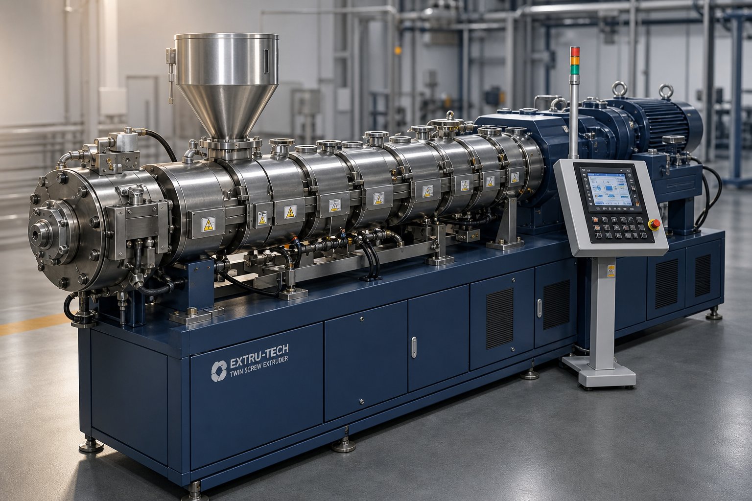
What Is a Twin Screw Extruder and Why You Need This Reference
Imagine you're evaluating a new compounding line, troubleshooting a vent-flow issue at 2 a.m., or comparing spec sheets from three different equipment suppliers. You need answers fast, and the last thing you want is to sift through a dozen scattered downloads hoping one of them covers your exact question. That frustration is precisely why so many engineers and processors search for a twin screw extruder PDF that pulls everything into a single, practical resource.
A twin screw extruder is a processing machine that uses two intermeshing or non-intermeshing screws, rotating inside a heated barrel, to continuously convey, melt, mix, and shape materials such as polymers, food ingredients, and pharmaceutical compounds.
Defining the Twin Screw Extruder
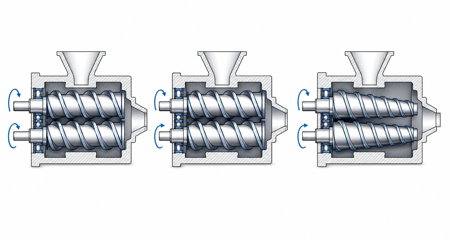
At its core, this machine relies on the coordinated rotation of two screws to move raw material forward while subjecting it to controlled heat, pressure, and shear. Depending on the configuration, the screws may rotate in the same direction (co-rotating) or in opposite directions (counter-rotating), and they can be arranged in parallel or conical geometries. The intermeshing design generates a self-wiping action that prevents material buildup on barrel walls, ensuring consistent and uniform processing. This versatility is what makes twin screw extruders the workhorse behind everything from engineering plastics and masterbatch production to pharmaceutical hot-melt extrusion and snack food texturization.
Why a Consolidated Reference Matters
If you've ever searched for twin screw extruders PDF resources online, you'll recognize the problem immediately. Some documents cover only the basics, offering little more than a glossary and a cross-section diagram. Others are brand-specific manuals locked behind vendor portals. Academic textbooks, while thorough, tend to bury practical guidance under dense mathematical models that rarely help on the production floor.
This guide is built to fill that gap. It integrates five key knowledge areas that processors and technical teams actually need in one place: fundamental operating principles, machine configurations, screw element design, critical process parameters, and real-world application guidance. Think of it as a twin screw extruders a basic understanding PDF evolved into a comprehensive, always-accessible web reference.
The structure is deliberately progressive. You'll move from types and configurations through individual components, into screw design strategy, then to operating parameters and how to decode specification sheets. From there, the focus shifts to industry applications, hands-on troubleshooting, and a terminology glossary you can bookmark for daily use. Whether you're a process engineer scaling up a new formulation or a maintenance technician diagnosing wear patterns, every section is designed to deliver actionable insight rather than theoretical filler.
The real value of any reference, though, starts with understanding what you're working with. And that means knowing how different twin screw configurations behave and which one fits your process.
Types and Configurations of Twin Screw Extruders Explained
Every twin screw extruder falls into a specific configuration family, and that configuration dictates everything from shear intensity to the kinds of products you can realistically produce. Pick the wrong one and you're fighting the machine instead of running a process. The challenge is that most co rotating twin screw extruder PDF resources cover only one or two variants, leaving you to piece together the full picture from multiple sources. Here's the complete breakdown.
Before diving into individual designs, it helps to see them side by side. The table below maps the primary configurations against the characteristics that matter most when selecting or evaluating equipment.
| Configuration | Rotation Direction | Intermeshing Type | Self-Wiping Capability | Typical Applications | Key Advantages |
|---|---|---|---|---|---|
| Co-Rotating Parallel | Same direction | Fully intermeshing | Yes | Polymer compounding, masterbatch, reactive extrusion, nanocomposites | High-speed operation, modular screw design, excellent dispersive and distributive mixing |
| Counter-Rotating Parallel | Opposite directions | Fully or partially intermeshing | Limited | PVC pipe, profile extrusion, sheet production | Low shear, high pressure generation, gentle conveying of thermally sensitive materials |
| Conical Counter-Rotating | Opposite directions | Fully intermeshing | Limited | PVC pipe and profile, medium-capacity lines | Compact footprint, high torque transmission, natural compression zone |
| Non-Intermeshing | Co-rotating or counter-rotating | None | No | Devolatilization, specialty reactive processing | Independent screw operation, gentle material handling, large free volume |
Co-Rotating Intermeshing Twin Screw Extruders
When engineers mention "twin screw compounding," they're almost always referring to the co-rotating intermeshing design. It dominates the market for a reason: both screws turn in the same direction with a fully intermeshing geometry that forces material from one screw flight to the next in a continuous figure-eight flow path. This handoff mechanism creates a self-wiping action that virtually eliminates dead zones inside the barrel, keeping residence time distribution tight and predictable.
Why does that matter? Imagine you're processing a heat-sensitive polymer blend or running a reactive extrusion where every second of extra thermal exposure degrades your product. A narrow residence time distribution means every particle of material spends roughly the same amount of time in the machine, giving you consistent melt quality from pellet to pellet.
Co-rotating extruders also excel at high screw speeds, often operating between 300 and 1,200 RPM depending on machine size. Their modular screw design lets you swap individual conveying elements, kneading blocks, and mixing elements along splined shafts, tailoring the screw configuration to each specific formulation. This flexibility is what makes them the standard choice for polymer compounding with inorganic and organic fillers, masterbatch production, polymer alloy development, and even nanocomposite processing where filler dispersion state directly influences final material properties.
The intense shear fields that develop both between the two screws and between each screw and the barrel wall produce excellent dispersive mixing. Kneading blocks add an elongational flow component, breaking up agglomerates and achieving fine-scale dispersion that gentler machines simply cannot replicate. However, that same shear intensity demands careful process design, especially with materials prone to degradation under high mechanical energy input.
Counter-Rotating Twin Screw Extruders
Flip one screw's rotation direction and the processing physics change dramatically. In a counter-rotating twin screw extruder, the screws turn in opposite directions, drawing material into the intermeshing region and compressing it forward. Rather than the figure-eight flow of co-rotating designs, material here follows a C-shaped flow chamber that acts almost like a positive displacement pump.
The result is a calendering effect at the intermeshing zone. Picture two roller mills pulling material through a narrowing gap: the material undergoes repeated compressive and elongational deformation rather than the high-shear tearing that characterizes co-rotating machines. Shear stress stays lower, shear-induced heat generation remains minimal, and the extruder can operate at comparatively low screw speeds under high fill conditions.
This gentler processing character is exactly why counter-rotating designs own the PVC market. Rigid PVC has a notoriously low thermal decomposition temperature combined with poor melt flow. Subject it to the aggressive shear of a co-rotating extruder and you risk degradation before the material even reaches the die. A counter-rotating machine, by contrast, holds the extrusion temperature low while building the high die pressure needed for pipe, profile, and sheet production. The calendering effect also provides effective dispersive mixing of stabilizers and other additives without the thermal penalty.
You'll find counter rotating twin screw extruder PDF resources frequently referencing these machines in the context of rigid and flexible PVC sheet lines, cable coating operations, and any process where pressure-building capability matters more than aggressive mixing intensity.
Conical Twin Screw Extruders
Take the counter-rotating concept and taper the screws from a large feed-end diameter down to a smaller discharge end, and you get the conical twin screw extruder. The tapered geometry creates a built-in compression zone: as material travels forward, the decreasing screw diameter naturally compresses and densifies it, generating substantial die pressure in a significantly shorter overall machine length.
That compact footprint is a practical advantage in plants where floor space is at a premium. The larger feed-end diameter also provides generous intake volume for accepting bulky powders and dry blends, while the smaller discharge end concentrates torque where pressure demands are highest. This geometric transition enhances melting, improves mixing performance, and facilitates efficient material conveyance, making conical designs a strong fit for medium-capacity extrusion lines in PVC processing.
If you encounter a conical twin screw extruder PDF specification, you'll notice that L/D ratios tend to be lower than parallel machines because the taper itself accomplishes compression work that would otherwise require additional barrel length. These machines are common in PVC pipe and window-profile production, where their combination of gentle conveying, high-pressure generation, and small physical footprint proves ideal.
Worth noting are non-intermeshing configurations, where the screw axes are spaced far enough apart that the flights don't engage each other. These niche designs sacrifice the self-wiping benefit but gain large free volume and independent screw operation, making them useful in devolatilization tasks and specialty reactive processing where gentle material handling outweighs mixing intensity.
Configuration choice, however, only tells half the story. The real performance of any twin screw extruder depends on the individual components that make up the machine, from the gearbox splitting torque between those two shafts all the way through to the die shaping the final product.
Key Components of a Twin Screw Extruder Machine and Their Functions
Strip away the housing panels from any twin screw extruder and you'll find a surprisingly logical chain of components, each one engineered to perform a specific job within the broader process. The trouble is, most twin screw extruder machine PDF documents show you a labeled cross-section and move on. Diagrams are helpful, but they rarely explain why a gearbox's torque-splitting mechanism limits your maximum throughput, or how the choice of barrel liner material affects wear life by thousands of operating hours. That practical depth is what this section delivers.
Here's the component chain in the order material encounters it, from the power source driving the screws to the die shaping your final product:
- Electric motor — supplies rotational energy to the system
- Coupling — connects the motor shaft to the gearbox input, absorbing misalignment and shock loads
- Gearbox — reduces motor speed, multiplies torque, and splits power evenly between two output shafts
- Screw shafts and screw elements — splined shafts carrying modular conveying, kneading, and mixing elements
- Barrel segments — individually heated and cooled sections bolted together to form the process channel
- Feed system — gravimetric or volumetric feeders delivering raw materials at controlled rates
- Vent ports — atmospheric or vacuum openings for moisture and volatile removal
- Side stuffers and liquid injection ports — downstream addition points for fillers, fibers, or liquid additives
- Die head — shapes the processed melt into strands, sheets, profiles, or directly into a pelletizer
Each of these components deserves a closer look, because the performance ceiling of your entire line often hinges on the weakest link in this chain.
Drive System and Gearbox
Think of the gearbox as the heartbeat of the extruder. The electric motor generates raw rotational speed, but it's the gearbox that converts that speed into usable torque and distributes it equally across two parallel output shafts. Without precise torque splitting, one screw would overpower the other, destroying the intermeshing geometry and the self-wiping action that makes twin screw extrusion so effective.
Modern twin screw extruder gearboxes are rated by their torque density, expressed in Nm/cm³ relative to the centerline distance between shafts. This single specification tells you more about gearbox capability than almost any other number on a spec sheet. A higher torque density means the gearbox can transmit greater torque within the same physical envelope, which translates directly into the ability to process higher-viscosity melts, run heavily filled formulations, and push throughput rates closer to the machine's volumetric limit.
Why does this matter on the production floor? Imagine you're compounding a 60% calcium carbonate-filled polypropylene. The filler loading dramatically increases melt viscosity, and the screws need substantially more torque to push that stiff compound forward. If your gearbox torque density is marginal, you'll hit the drive's torque ceiling before reaching target throughput, and the control system will either trip the motor or automatically reduce screw speed. A gearbox designed with high torque density, by contrast, provides the power reserves to handle demanding materials without throttling production.
Gearbox internals typically feature hardened alloy steel gears, high-capacity thrust and radial bearings, and forced lubrication systems with integrated cooling circuits. These elements collectively determine maximum screw speed, continuous operating torque, and long-term reliability. Any twin screw extruder gearbox PDF worth referencing should list not just output torque and RPM range, but also bearing type, lubrication method, and thermal management design, because these factors govern maintenance intervals and service life under continuous production loads.
Barrel Segments and Screw Shafts
If the gearbox is the heartbeat, the barrel-and-screw assembly is the digestive system. This is where raw materials are conveyed, melted, mixed, devolatilized, and pressurized on their way to the die.
Twin screw extruder barrels are not monolithic. They're constructed from individual barrel segments, typically 4D to 5D in length (four to five times the screw diameter), bolted together in series to create the full process length. Each segment contains its own electric heating elements and water-cooling channels, forming an independent temperature zone. This modularity is a defining advantage: you can configure the barrel layout with solid segments, open feed ports, atmospheric vent ports, vacuum vent ports, side-stuffer openings, or liquid injection points at any position along the process length.
Barrel liners receive special attention because they endure constant abrasive contact with the processed material. Standard liners are made from nitrided steel for general-purpose compounding. For highly abrasive formulations, such as glass-fiber-reinforced or mineral-filled compounds, manufacturers use bimetallic liners with a hard alloy inlay (typically iron-boron or nickel-based alloys) that can extend wear life by two to five times compared to standard nitrided surfaces. Selecting the right liner material isn't optional; it's the difference between a barrel that lasts three years and one that needs replacement in six months.
Inside the barrel, the screw shafts run on involute splines that accept individual screw elements. The elements slide onto the shaft and are locked in sequence with a screw tip at the discharge end. This means you can disassemble the screw, rearrange elements, swap worn kneading blocks, or reconfigure the entire screw profile for a new formulation without replacing the shaft itself. Sourcing high-quality replacement screw barrels and machine-specific components is essential for maintaining extruder performance over time. For teams managing pipe, profile, sheet, pelletizing, or recycling lines, NANHAIYA's screw barrel support for plastic extruder machines provides a practical connection point for compatible screw and barrel components, covering a broad range of machine types and process applications.
The spline interface between shaft and elements also plays a critical role. Over thousands of operating hours, torque transmission through the splines generates micro-wear that eventually leads to looseness and element rotation on the shaft. Inspecting spline condition during routine maintenance is one of the most overlooked yet impactful steps in preserving melt quality and preventing unplanned downtime.
Feed Systems and Die Heads
Everything upstream and downstream of the barrel-screw assembly directly shapes your final product quality, yet these components rarely get the attention they deserve in a typical leistritz twin screw extruder manual PDF or similar reference document.
Feeding starts the process. Co-rotating twin screw extruders operate on a starve-fed principle, meaning the feed system, not the screw speed, controls how much material enters the barrel. Two main feeder types handle this job:
- Volumetric feeders deliver material at a fixed volume per unit time. They're simpler and less expensive but don't compensate for bulk density variations in the feedstock. If your raw material lot changes density, your actual mass flow rate drifts.
- Gravimetric feeders use a loss-in-weight measurement to maintain a constant mass flow rate, automatically adjusting screw or belt speed to compensate for density changes. For any process where formulation accuracy matters, gravimetric feeding is the standard.
Downstream along the barrel, side stuffers introduce fillers, glass fibers, or other solid additives directly into the melt. These are typically twin-screw feeders mounted perpendicular to the main barrel, using their own drive to force low-bulk-density materials into the pressurized process channel. Side feeding is critical when you need to add abrasive or fragile reinforcements after the polymer is already molten, preventing excessive fiber breakage or premature wear of upstream screw elements.
Vent ports serve as the extruder's exhaust system. Atmospheric vents allow trapped air and light volatiles to escape under ambient pressure. Vacuum vents, connected to a vacuum pump, pull moisture, residual monomers, and reaction byproducts out of the melt at sub-atmospheric pressure. Proper vent placement, always positioned above a low-fill, low-pressure zone in the screw configuration, is what separates clean, void-free product from material riddled with bubbles and surface defects.
At the discharge end, the die head receives the homogenized, pressurized melt and shapes it into the desired product form. Common die configurations include:
- Strand die — produces multiple spaghetti-like strands that are water-cooled and pelletized by a strand cutter
- Underwater pelletizing die — extrudes melt through a die plate directly into a water-filled cutting chamber for immediate pelletization and cooling
- Sheet and film dies — flat dies producing wide, thin product for calendering or winding
- Profile dies — custom-shaped openings for producing window profiles, tubing, or other continuous cross-sections
Each die type imposes different back-pressure requirements on the extruder, which in turn influences screw configuration, barrel temperature profile, and overall energy consumption. Selecting the wrong die for your process doesn't just affect product shape; it can cascade into melt quality issues, surging, and premature component wear.
With every physical component mapped and its role understood, the real question becomes: how do those modular screw elements sitting on the splined shafts actually control what happens to the material? That answer lives in the geometry of individual conveying elements, kneading blocks, and specialized mixing inserts, and how their arrangement creates distinct functional zones along the process length.
Screw Element Design Fundamentals for Twin Screw Extruders
A single co-rotating twin screw extruder can behave like two entirely different machines depending on how its screw elements are arranged. Swap a few kneading blocks, change a pitch, reverse one element, and you shift from gentle distributive blending to aggressive dispersive deagglomeration. That modularity is the defining advantage of the platform, and it's also the reason twin screw extruder design PDF searches remain so common: getting the element selection right is both an engineering discipline and a practical art.
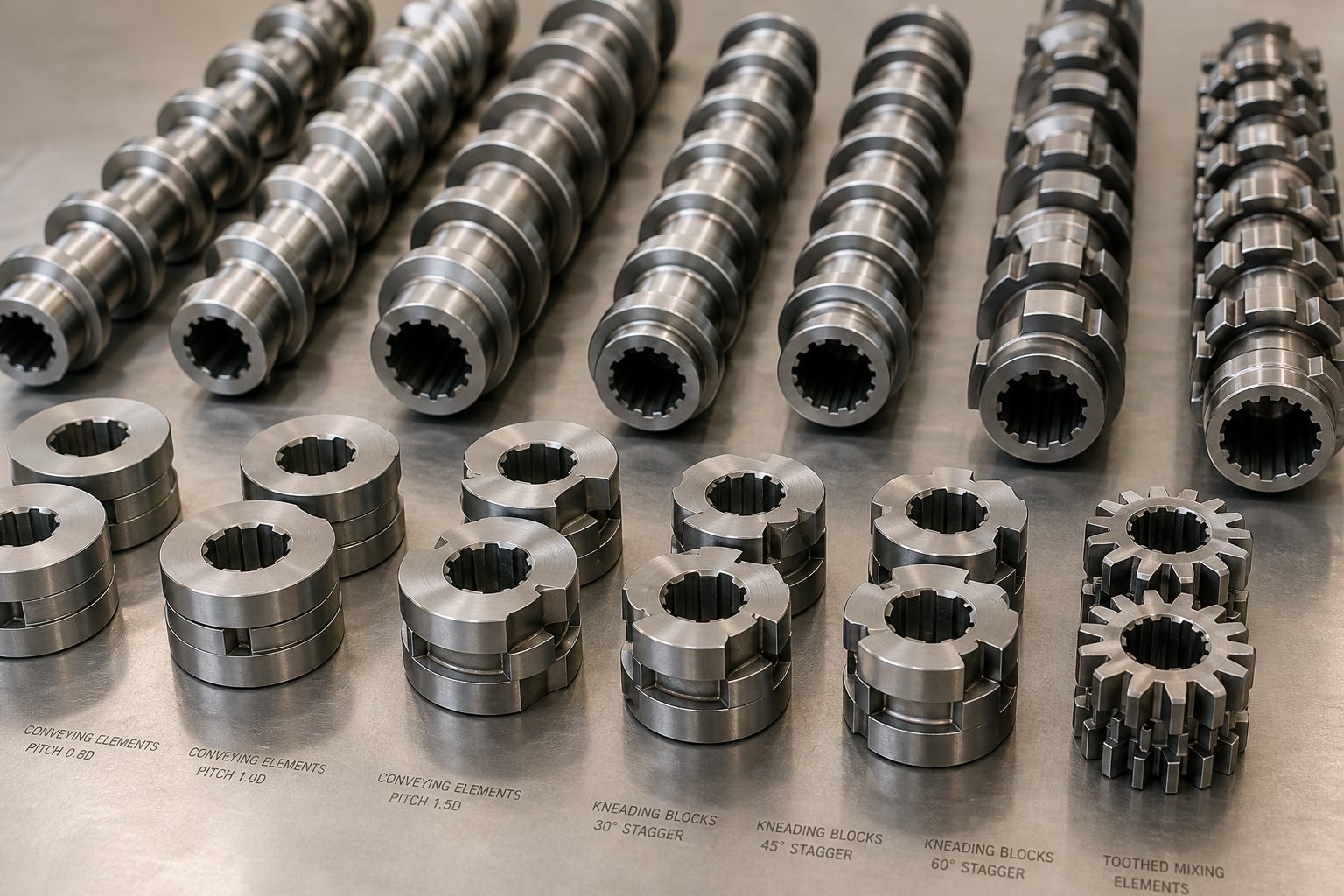
The table below maps the primary element families against their geometry, function, and typical location along the screw profile. Use it as a quick-reference tool when evaluating or modifying a configuration.
| Element Type | Geometry Description | Primary Function | Typical Placement Zone |
|---|---|---|---|
| Forward-conveying (wide pitch) | Helical flights with large axial pitch and deep channels | High-volume solids intake; rapid material transport | Feed zone, downstream of side stuffers |
| Forward-conveying (narrow pitch) | Helical flights with reduced axial pitch | Increased fill level, compression, and pressure building | Metering zone, pre-die pressurization |
| Reverse-pitch conveying | Helical flights with opposite hand of rotation | Creates upstream back-pressure and melt seals | Upstream of vent ports, between mixing zones |
| Forward kneading block | Stacked discs offset at low stagger angle (e.g., 30°) | Distributive mixing with moderate forward conveying | Initial mixing zone, gentle blending sections |
| Neutral kneading block | Stacked discs offset at 90° stagger angle | Intensive mixing with zero net conveying | Primary dispersion zone |
| Reverse kneading block | Stacked discs with reverse stagger orientation | High-intensity dispersive mixing; melt seal generation | Deagglomeration zone, upstream of vacuum vents |
| Toothed mixing element (TME) | Gear-like teeth arranged circumferentially | Distributive mixing with low shear stress | Final homogenization zone, heat-sensitive blends |
| Screw mixing element (SME) | Conveying flights with interrupted channels or slotted geometry | Combined distributive and dispersive action | Secondary mixing zone, fiber-reinforced compounds |
Conveying Elements and Their Pitch Variations
Conveying elements are the workhorses of material transport. They look like traditional helical screws, but their pitch, the axial distance between consecutive flights, varies deliberately along the screw profile to control fill level, throughput, and pressure.
In the feed zone, you'll typically find wide-pitch elements. Their deep channels and large open volume grip incoming pellets or powder and move them forward quickly, preventing feed-port bridging and ensuring smooth material intake. As a rule of thumb, larger pitch increases theoretical conveying capacity while generating relatively little pressure.
Farther downstream, the pitch narrows. Reduced pitch compresses material, increases barrel fill, and starts building the pressure needed to push melt through restrictive mixing zones and ultimately through the die. Think of it like a highway on-ramp merging into a two-lane road: narrowing the channel forces material to slow down and pack together, raising both local pressure and shear.
Reverse-pitch elements deserve special attention. These elements have the opposite hand of rotation, meaning they actively push material backward against the overall forward flow. Sounds counterproductive? It's actually one of the most powerful tools in screw configuration. Placing a short reverse-pitch element upstream of a vent port creates a melt seal, a fully filled zone that prevents molten material from crawling up through the vent opening. It also builds significant back-pressure that intensifies mixing in the upstream kneading zone by forcing material to spend more time under shear. According to NC State Extension's research on screw functionality, reverse elements ensure maximum restriction in forward flow, creating the conditions necessary for thorough melting and homogenization.
The limitations of conveying elements are equally important to understand. They provide limited distributive mixing and weak dispersive mixing compared to kneading blocks and dedicated mixing elements. Relying on conveying elements alone for mixing typically leads to poor additive distribution and visible defects in the finished product.
Kneading Blocks and Mixing Elements
If conveying elements are the workhorses, kneading blocks are the precision instruments. They consist of multiple discs stacked on the splined shaft, each disc offset from the next by a defined stagger angle. Three design variables largely determine how a kneading block behaves: disc width, the number of discs in the block, and stagger angle.
Here's how each variable shapes the mixing outcome:
- Disc width controls the transition between distributive and dispersive action. Narrower discs create more frequent cross-sectional flow changes, generating higher local pressure fluctuations and more opportunities for extensional flow that fractures agglomerates. Wider discs produce smoother, gentler flow paths better suited to distributive blending without aggressive shear.
- Stagger angle is the angular offset between adjacent discs. A 30° stagger promotes forward pumping with moderate shear, favoring distributive mixing. A 60° stagger provides a balanced combination. A 90° stagger eliminates net conveying entirely, meaning material oscillates back and forth across the block, dramatically increasing residence time and shear intensity for strong dispersive action.
- Block length (number of discs) governs total energy input. Longer blocks deliver more repeated splitting and recombining of material, but they also raise melt temperature and torque demand. Shorter blocks offer localized effects without spiking the thermal load.
Sounds complex? A practical shorthand simplifies the logic: narrow discs + high stagger angle + longer block = aggressive dispersive mixing for breaking stubborn pigment agglomerates or deagglomerating silica clusters. Wide discs + low stagger angle + shorter block = gentle distributive mixing for color masterbatch blending or fiber-reinforced compounds where you need to maintain filler morphology and avoid excessive fiber breakage.
Beyond standard kneading blocks, specialized mixing elements fill critical processing niches. Toothed mixing elements (TME) use gear-like teeth arranged circumferentially to repeatedly divide and recombine the melt stream with very low shear stress, making them ideal for heat-sensitive materials. Screw mixing elements (SME) combine conveying geometry with interrupted or slotted flights, delivering both distributive and dispersive action simultaneously. These elements appear frequently in co-rotating twin-screw extruders fundamentals technology and applications PDF references as solutions for processes that demand mixing versatility without the thermal penalty of long kneading block sequences.
Zoning and Configuration Strategy
Individual elements only matter in context. A 90° kneading block placed in the wrong zone can cause torque spikes and polymer degradation. The same block in the right position delivers exactly the dispersion you need. That's why experienced process engineers think in terms of functional zones rather than isolated elements.
A complete screw configuration divides the barrel length into a sequence of zones, each defined by the elements populating it:
- Feeding zone — Wide-pitch conveying elements grip raw material and transport it forward with minimal compression. The goal is smooth, surge-free intake.
- Melting/plasticizing zone — Conveying elements with gradually decreasing pitch, often paired with mild forward kneading blocks, transition the material from solid to melt. Controlled energy input here prevents unmelted particles from reaching downstream mixing sections.
- Primary mixing zone — Kneading blocks with appropriate disc width and stagger angle disperse pigments, deagglomerate fillers, or blend polymer alloys. This is where the heaviest shear and energy input occur.
- Venting zone — Conveying elements reduce pressure and increase surface area for moisture and volatile removal. Reverse elements or reverse kneading blocks upstream create the melt seal that prevents material from exiting through the vent port.
- Secondary mixing/homogenization zone — Lower-intensity mixing elements or gentle kneading blocks complete distribution without overheating the melt. TME and SME elements are common here.
- Metering and pressurization zone — Narrow-pitch conveying elements build stable, uniform pressure at the die for consistent output and dimensional control.
The arrangement of elements within each zone directly determines three outcomes that define product quality: residence time distribution (how uniformly material spends time in the extruder), melt temperature (from the balance between viscous dissipation and barrel heating or cooling), and mixing intensity (from the cumulative shear and elongational flow history). As NC State Extension notes, no gold standard exists for screw profile design because every material exhibits unique flow properties under different temperature and shear conditions. That reality is precisely what makes the modular approach so valuable: you can iterate, test, and refine without building a new screw from scratch.
Any twin screw extruder book PDF will tell you that screw design matters. What separates a productive line from a frustrating one is understanding how element geometry translates into specific process outcomes, and then pairing that understanding with the operating parameters, screw speed, feed rate, barrel temperature, and vent vacuum, that bring the configuration to life.
Critical Twin Screw Extruder Process Parameters and How They Interact
A perfectly configured screw profile sitting inside a flawless barrel assembly will still produce garbage if the operating parameters are wrong. Screw speed, feed rate, barrel temperatures, and vacuum levels form an interconnected web where adjusting one variable inevitably shifts the others. Yet most twin screw extruder operating parameters PDF resources treat each setting in isolation, listing recommended ranges without explaining the cause-and-effect relationships that actually govern melt quality, dispersion, and throughput. This section closes that gap with practical guidance you can apply directly on the production floor.
Screw Speed and Feed Rate Relationships
Here's something that surprises newcomers to co-rotating twin screw extrusion: the screws don't determine how much material flows through the machine. The feeder does. Unlike a single-screw extruder, where screw rotation drags material forward in a flood-fed barrel, co-rotating twin screw extruders operate on a starve-fed principle. The feed system meters material into the barrel at a controlled mass rate, and the screws simply process whatever arrives. Screw speed and feed rate are set independently, and their ratio is where the real process control lives.
Imagine running a 50-mm extruder at 300 RPM with a feed rate of 150 kg/hr. You're putting 0.5 kg into the barrel for every revolution of the screw. Increase screw speed to 600 RPM without changing the feed rate, and each revolution now processes only 0.25 kg. The barrel becomes more starved, the degree of fill drops, and every particle of material experiences more shear passes before exiting the die. This concept is captured by a metric called specific throughput, defined as output in kg/hr divided by screw RPM. As industry experts have noted, specific throughput provides a proportional indicator of fill level and serves as a practical tool for scaling similar products across different rates on the same machine or even across different machine sizes.
Why does this matter? Because the feed-rate-to-screw-speed ratio directly governs three critical process outcomes:
- Residence time — Lower fill levels mean material spends more time exposed to heat and shear in the barrel. Higher fill levels tighten the residence time distribution, meaning every particle exits at roughly the same age.
- Shear history — At a given feed rate, higher RPM increases the number of shear events each material element encounters. More shear improves dispersive mixing but also raises melt temperature through viscous dissipation.
- Specific energy input — Defined as the motor power consumed per kilogram of material processed (kW·hr/kg), specific energy captures the total mechanical work done on the material. A consistent specific energy value across production runs signals process stability; a sudden shift, with no hardware changes, often points to feedstock variation.
The specific energy formula is straightforward: multiply the motor's rated power by the percentage of torque being used, factor in the ratio of running RPM to maximum RPM, account for gearbox efficiency (typically around 97%), and divide by the throughput in kg/hr. Tracking this number over time is one of the most powerful troubleshooting tools available. If a product that normally runs at a specific energy of 0.25 kW·hr/kg suddenly drops to 0.16, something has changed in the feedstock, not the machine.
Barrel Temperature Zones and Thermal Management
Walk up to any twin screw extruder control panel and you'll see a row of temperature setpoints stretching across the screen, one for each barrel segment. Each zone has its own electric heaters and water-cooling channels, making the barrel a finely tunable thermal environment. But here's the catch: the temperature you set on the controller is the barrel wall temperature, not the melt temperature. The two can differ by 20°C or more, and understanding why is essential to effective thermal management.
Inside a twin screw extruder, heat arrives from multiple sources simultaneously. Technovel's research into plastication mechanisms identifies four overlapping categories: heat from plastic deformation of solid pellets, viscous dissipation in the melt, friction between material and metal surfaces, and conduction from barrel heaters. During startup and at low screw speeds, conduction from the heaters dominates. But once steady-state operation is reached at moderate to high RPM, viscous dissipation from the rotating screws frequently contributes more thermal energy than the heaters themselves. In high-viscosity formulations or at aggressive screw speeds, the barrel cooling system may be working hard to remove heat even while the heater setpoints remain well above ambient.
This reality leads to the concept of adiabatic processing, where barrel heaters are effectively turned off and the process generates all the thermal energy it needs through mechanical shear alone. Adiabatic operation is common in high-speed compounding of polyolefins and other semi-crystalline polymers where throughput is maximized and the motor provides ample energy. In contrast, actively heated profiles are necessary during startup phases, when processing low-viscosity or thermally sensitive materials, or when barrel zones near the feed throat need elevated temperatures to initiate melting.
A practical twin screw extruder temperature profile PDF reference should distinguish between three operating regimes:
- Ascending profile — Barrel temperatures increase gradually from feed to die. Common for materials requiring progressive melting and for processes where the polymer benefits from increasing fluidity toward the discharge end.
- Hump profile — Mid-barrel temperatures peak higher than both feed and die zones. Used when aggressive melting and mixing are needed in the center of the machine while the melt must cool slightly before exiting through a thermally sensitive die.
- Flat or descending profile — Temperatures are uniform or decrease toward the die. Typical of adiabatic or near-adiabatic operation where viscous dissipation dominates and barrel cooling actively pulls excess heat from the melt.
Regardless of the profile shape, remember that changing a barrel zone setpoint doesn't instantly change the melt temperature at that location. Barrel heating affects primarily the thin material layer near the wall, while the bulk melt temperature depends on the cumulative shear history imposed by the screw configuration and RPM. That distinction is why two extruders running identical barrel temperatures can produce measurably different melt temperatures if their screw configurations or screw speeds differ.
Vacuum Vent Positioning and Devolatilization
Moisture, trapped air, residual monomers, and reaction byproducts don't belong in your finished product. Removing them efficiently requires more than just drilling a hole in the barrel and connecting a vacuum pump. Effective devolatilization depends on the interplay between vent port placement, screw element configuration, fill level, and vacuum intensity.
A devolatilization zone in a twin screw extruder follows a consistent design logic. As Rob Jerman explains in his analysis of devolatilization fundamentals, the vent port sits over a partially filled section of the screw, isolated between two fully filled "sealed" sections. The upstream seal is created by a restrictive element, typically a reverse kneading block or reverse-pitch conveying element, that forces the screw to be completely full, preventing air from entering the vent zone from the feed end. The downstream seal, often the die itself or another restrictive element, prevents vacuum from pulling through the forward screw section and disrupting the vent's performance.
Between these seals, the screw runs at low fill level. Wide-pitch conveying elements in the vent zone maximize the exposed melt surface area, allowing volatiles to flash off under reduced pressure. A practical rule of thumb holds that each properly designed vent stage can reduce volatile concentration by roughly one order of magnitude. A triple-vented extruder, for example, can take a 50%-solids feed stream down to below 0.1% residuals.
Vent stability is sensitive to operating conditions. Increase screw speed without adjusting feed rate and the filled length behind each seal shortens, potentially allowing the seal to fail and air to leak into the process. Decrease screw speed too far and the filled length behind the downstream seal extends backward under the vent opening, causing melt to flood up into the vent port, a problem known as vent flooding. The operator must understand these dynamics, because as devolatilization specialists note, changes in screw speed directly alter seal stability in twin screw extruders.
Atmospheric vents serve lighter-duty roles: releasing trapped air during initial feeding and allowing low-boiling-point volatiles to escape without the cost of a vacuum system. Vacuum vents, typically operating at 20 to 100 mbar absolute, handle more demanding tasks such as stripping moisture from hygroscopic polymers, removing residual monomers, and extracting reaction byproducts during reactive extrusion.
Pulling these twin screw extrusion process parameters together, the key interactions that every operator and process engineer should internalize are:
- Screw speed ↔ Shear rate: Higher RPM increases shear intensity, improving dispersive mixing but also raising melt temperature through viscous dissipation
- Feed rate ↔ Fill level: At constant screw speed, increasing feed rate raises barrel fill, tightening residence time distribution and reducing shear per unit mass of material
- Barrel temperature ↔ Melt viscosity: Higher barrel temperatures reduce viscosity, lowering torque demand and shear-induced heating, but risk thermal degradation if pushed beyond the material's stability window
- Vent vacuum ↔ Volatile removal efficiency: Deeper vacuum lowers the partial pressure of volatiles at the melt surface, driving faster mass transfer, but requires robust melt seals and stable fill levels to prevent vent flooding
None of these parameters exist in isolation. Adjusting screw speed to improve mixing simultaneously changes fill level, residence time, melt temperature, and vent seal stability. That interconnectedness is precisely why experienced operators develop an intuitive feel for the machine over time, and why tracking metrics like specific energy and specific throughput across production runs turns raw data into actionable process intelligence.
Understanding how these parameters interact is one thing. Translating that knowledge into a confident equipment evaluation, where you're comparing spec sheets from multiple suppliers and need to know exactly what each number means, is another challenge entirely.
How to Read Twin Screw Extruder Specification Sheets
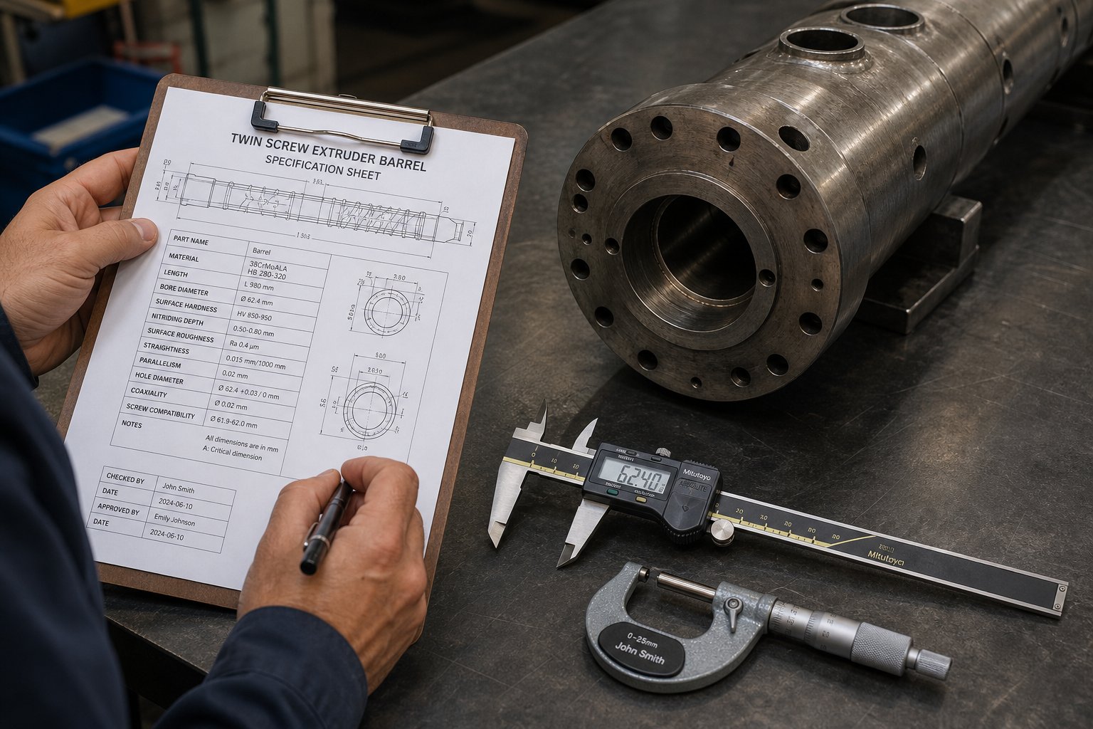
You've got three spec sheets open on your desk from three different equipment suppliers. The numbers look similar at first glance, but buried in the details are differences that will determine whether your next machine hits throughput targets or falls short by 30%. The problem? Most twin screw extruder specifications PDF documents assume you already know what every parameter means and why it matters. That assumption leaves engineers comparing numbers they can't fully interpret, and it leads to expensive purchasing mistakes.
This section gives you the decoder ring. The table below maps the most common spec sheet parameters against their units, definitions, and practical significance. Whether you're reviewing a Coperion twin screw extruder PDF, a Steer data sheet, or any other manufacturer's offering, these are the numbers that separate one machine class from another.
| Parameter | Unit | Definition | Why It Matters |
|---|---|---|---|
| Screw Diameter (D) | mm | Outer diameter of the screw flights | Defines machine size class; directly correlates with throughput capacity and capital cost |
| L/D Ratio | Dimensionless (e.g., 40:1) | Process length divided by screw diameter | Determines the number of functional zones available for feeding, mixing, venting, and pressurization |
| Maximum Screw Speed | RPM | Highest rotational speed the drive system can sustain continuously | Sets the upper limit of shear intensity and throughput potential |
| Total Drive Power | kW | Combined motor power available to both screws | Limits maximum specific energy input; undersized motors restrict throughput on high-viscosity materials |
| Maximum Torque per Shaft | Nm | Peak continuous torque transmitted to each screw shaft | Defines the machine's ability to process high-viscosity melts and heavily filled compounds |
| Torque Density | Nm/cm³ | Torque per unit of centerline distance cubed (a3) | The single most important performance indicator for comparing modern gearbox designs across manufacturers |
| Free Volume | cm³/D or L/hr | Open volume inside the barrel available for material | Governs throughput capacity for low-bulk-density materials like powders, fibers, and recycled flake |
| Do/Di Ratio | Dimensionless | Ratio of screw outer diameter to inner (root) diameter | Balances free volume against shaft strength for torque transmission |
| Number of Barrel Zones | Count | Independently heated and cooled barrel segments | More zones enable finer thermal control and greater screw configuration flexibility |
| Specific Torque | Nm/cm³ at max RPM | Torque available when the machine runs at its rated maximum screw speed | Defines the usable operating envelope; low specific torque narrows the range of processable formulations |
Understanding Screw Diameter and L/D Ratio
Screw diameter is the first number you'll see on any spec sheet, and for good reason: it defines the machine's size class. A 27-mm extruder is a lab or pilot machine. A 70-mm unit handles mid-scale compounding. A 135-mm or larger system serves high-volume production. Throughput capacity scales roughly with the square of the diameter, so doubling the screw diameter doesn't double your output; it can potentially quadruple it, depending on formulation and screw speed.
L/D ratio, the process length divided by that screw diameter, tells you how much working space the machine offers along its length. A shorter L/D, say 24:1 to 32:1, provides fewer barrel segments and limits the number of functional zones you can configure. That might be perfectly adequate for simple color masterbatch blending where you need a feed zone, one mixing section, and a metering zone. But try to run a reactive extrusion with upstream feeding, two mixing stages, a devolatilization vent, downstream side-stuffing, and a final homogenization section on a 28:1 machine, and you'll run out of barrel length before you run out of process steps.
Longer L/D ratios, from 40:1 up to 52:1 and beyond, give you the real estate for complex screw configurations. Each additional barrel segment opens another potential zone for feeding, mixing, venting, or injection. According to Wanplas's L/D selection guide, ratios of 36:1 to 48:1 are commonly employed for applications requiring extended residence time, such as devolatilization, reactive extrusion, or processing of highly filled compounds. A 40:1 machine, for example, might dedicate six diameters to feeding, eight to melting and primary mixing, four to venting, another six to downstream filler addition and secondary mixing, and the remaining barrels to homogenization and pressurization. That kind of zonal complexity is impossible on a short-barreled machine.
When comparing twin screw extruder specifications PDF documents from different manufacturers, always verify whether the stated L/D includes or excludes the die adapter. Some suppliers count the adapter in their published L/D, inflating the number without adding usable process length.
Torque Density and Free Volume Explained
If screw diameter tells you the machine's size and L/D tells you its length, twin screw extruder torque density tells you its strength. Torque density is defined as the maximum torque per shaft divided by the cube of the centerline distance between the two screw axes (a3), typically expressed in Nm/cm³. It normalizes gearbox performance across different machine sizes, making it the fairest way to compare one manufacturer's 50-mm extruder against another's.
Why does torque density matter so much? Because torque is what pushes material forward against resistance, and resistance increases with melt viscosity, filler loading, and die restriction. A machine with a torque density of 10 Nm/cm³ might handle neat polymer compounding without breaking a sweat. But load it with 65% calcium carbonate in a polyolefin matrix and the torque demand can spike beyond what the gearbox can deliver. Modern high-performance extruders have pushed torque densities to 18 Nm/cm³ and higher, enabling formulations that were simply impossible on older equipment. When evaluating a Coperion twin screw extruder PDF or a Steer twin screw extruder PDF, compare torque density numbers directly. A machine with higher torque density gives you more processing headroom for high-viscosity materials, higher filler concentrations, and future formulation development without upgrading hardware.
Free volume answers a different question: how much space is available inside the barrel for material? It's determined by the screw geometry, specifically the channel depth and flight-tip clearance, and it matters most when you're processing low-bulk-density feedstocks like recycled flake, wood fiber, or expanded microspheres. High free volume means the screws can grab and convey more material per revolution, directly boosting the intake capacity of the feed zone. If your feedstock is fluffy or irregularly shaped, a machine with generous free volume will outperform a tight-clearance design at the same screw speed.
Maximum RPM and Specific Torque Considerations
Maximum screw speed gets a lot of attention on spec sheets because it sounds impressive. A machine rated for 1,200 RPM certainly seems more capable than one rated for 600 RPM. But raw RPM only tells part of the story. What you really need to know is how much torque the gearbox can still deliver at that maximum speed.
This is where specific torque comes in. It represents the torque available at the maximum rated RPM, and it defines the machine's usable operating envelope. Consider two machines, both with identical maximum torque ratings. Machine A tops out at 600 RPM. Machine B reaches 1,200 RPM. If both gearboxes deliver the same peak torque, Machine B can only sustain that torque at its lower speed range, not at 1,200 RPM, because power equals torque multiplied by speed, and motor power is finite. At maximum RPM, the available torque drops proportionally. A practical formula ties these together: Torque (Nm) = 9,550 x Power (kW) / RPM. A 200 kW motor at 500 RPM delivers about 3,820 Nm per shaft, but that same motor at 1,000 RPM can only sustain roughly 1,910 Nm.
This trade-off means high-RPM capability is most valuable for low-viscosity, lightly filled formulations where torque demand is modest and throughput benefits from faster screw rotation. High-viscosity or heavily filled formulations, by contrast, need torque more than speed, and running these at elevated RPM pushes the drive into torque-limited operation, where the control system throttles performance to protect the gearbox.
The Do/Di ratio, the ratio of screw outer diameter to inner (root) diameter, sits at the heart of this trade-off. A larger Do/Di ratio creates deeper screw channels and greater free volume, boosting intake and throughput capacity. But the thinner root diameter reduces shaft stiffness and limits the torque that can be transmitted through the splines. A smaller Do/Di ratio, conversely, produces a thicker, stronger shaft that handles higher torque loads, but sacrifices channel depth and free volume. Modern designs typically range from 1.55 to 1.71, with each manufacturer optimizing the ratio for their target application mix.
When you sit down to compare spec sheets, resist the temptation to focus on any single number. Screw diameter, L/D ratio, torque density, free volume, maximum RPM, and Do/Di ratio form an interconnected system. A machine with exceptional torque density but a short L/D may not suit your multi-stage process. One with generous free volume but low torque density will struggle with filled formulations. The strongest evaluations weigh all these parameters together against your specific material, throughput, and process requirements.
Specification numbers tell you what the machine can do. Seeing where it fits in practice, across real industries and real production challenges, reveals what it should do.
Twin Screw Extruder Applications Across Industries
Specification sheets quantify what a machine can deliver. Real-world applications reveal why those specifications exist in the first place. Every torque density rating, every L/D ratio, and every free volume figure on a data sheet traces back to a specific processing challenge in a specific industry. Yet most twin screw extruder applications PDF resources stop at listing markets without explaining what makes the technology uniquely suited to each. That shallow treatment leaves engineers wondering whether a twin screw extruder is truly the right tool or just a popular one.
The answer varies by industry, and the reasons are worth understanding. Here's a breakdown of the major application sectors and the processing characteristics that drive twin screw adoption in each:
- Polymer compounding and masterbatch
- Recycling, bioplastics, and emerging technologies
- Pipe, profile, sheet, and pelletizing production lines
Polymer Compounding and Masterbatch Production
This is the core application, the one that shaped the co-rotating twin screw extruder into the machine it is today. Compounding means blending a base polymer with additives, fillers, pigments, flame retardants, impact modifiers, or reinforcing fibers to create a material with precisely targeted properties. Think 40% glass-fiber-reinforced nylon for under-hood automotive parts, or a carbon black masterbatch that must disperse uniformly across billions of thin-film grocery bags without a single visible speck.
Why do twin screw extruders dominate this space? Three reasons converge. First, the modular screw design lets you place aggressive kneading blocks exactly where pigment agglomerates need to be fractured, then switch to gentle distributive elements downstream where fiber length must be preserved. Second, independently controlled barrel temperature zones allow precise thermal management across materials with vastly different melting points and degradation thresholds. Third, the superior dispersive and distributive mixing inherent in the intermeshing co-rotating geometry produces a level of homogeneity that single-screw machines and batch mixers simply cannot match at comparable throughput rates.
A twin screw extruder polymer compounding PDF from any major manufacturer will highlight these same strengths. Engineering thermoplastics like polycarbonate/ABS blends, mineral-filled polypropylene for appliance housings, and color masterbatch for packaging films all rely on this combination of configurable mixing intensity, thermal precision, and continuous high-volume output.
Recycling, Bioplastics, and Emerging Applications
If compounding represents where twin screw extrusion matured, recycling and bioplastics represent where it's heading next. Post-consumer recycled plastics arrive at the extruder with wildly inconsistent contamination levels: residual moisture, paper labels, mixed polymer fractions, odor-causing volatiles, and trace metals. Processing this feedstock into usable pellets demands exactly the capabilities twin screw extruders deliver best: multi-stage devolatilization through sequenced vacuum vents, melt filtration integration for removing solid contaminants, and flexible screw configurations that adapt to batch-to-batch variability. Any comprehensive twin screw extruder recycling applications PDF will emphasize that the starve-fed operating principle is particularly valuable here, because it decouples feed rate from screw speed, allowing operators to adjust shear intensity and residence time independently as incoming material quality shifts.
Bioplastics present a different but equally demanding challenge. Materials like PLA, PHA, and thermoplastic starch are notoriously sensitive to moisture and thermal exposure. PLA's sensitivity to moisture, temperature, and shear demands precise process control and tailored formulations to prevent molecular weight loss and discoloration during extrusion. Twin screw extruders address this through tight residence time distribution, where every particle spends a nearly identical amount of time in the barrel, combined with the ability to position vacuum vents precisely where moisture removal is most effective. The compounding of bioplastics and natural fiber composites on twin screw extruders has become a dedicated area of process development, with equipment manufacturers offering specialized workshops and application-specific screw configurations for heat- and shear-sensitive bio-based formulations.
Beyond plastics entirely, twin screw extruders have carved out roles in industries that might surprise you:
- Pharmaceutical hot-melt extrusion — Enhances solubility and bioavailability of poorly soluble drugs by creating solid dispersions and controlled-release formulations with tightly controlled residence time and temperature
- Food processing — Produces textured vegetable proteins, snack foods, and breakfast cereals through high-moisture extrusion cooking, where the twin screw design provides the precise shear and temperature control needed for protein texturization
- Battery electrode paste — Continuously mixes active materials, binders, and conductive additives for lithium-ion battery cathode and anode slurries, replacing batch mixing with higher consistency and throughput
- Ceramic processing — Compounds ceramic powders with organic binders for injection molding feedstocks, leveraging the extruder's ability to handle high-solids-loading formulations under controlled thermal conditions
Each of these emerging applications exploits the same fundamental twin screw advantages: modular configuration, independent thermal zoning, and precise control over shear and residence time. The machine architecture doesn't change; the screw profile and operating parameters do.
Pipe, Profile, Sheet, and Pelletizing Lines
When you see a PVC window profile or a polyethylene drainage pipe, you're looking at the output of a complete extrusion line, not just an extruder. The twin screw extruder is one component, arguably the most critical one, within a broader system that includes downstream equipment tailored to the specific product form.
For pipe production, the extruder feeds homogenized melt into an annular die, and the emerging tube passes through a vacuum calibration tank that sizes and cools the pipe to dimensional tolerances, followed by spray cooling tanks, a haul-off puller maintaining constant line speed, and a planetary or saw cutter producing finished lengths. Profile lines follow a similar sequence but replace the annular die with a custom-shaped opening and add calibration tooling matched to the profile's cross-section. Sheet lines use flat dies feeding into a set of polishing and cooling rolls (a calendar stack), then a haul-off and winder or sheet cutter.
Pelletizing, the most common downstream configuration for compounding operations, takes two primary forms. Strand pelletizing pulls cooled polymer strands through a water bath and into a rotary cutter. Underwater pelletizing pushes melt directly through a die plate into a water-filled cutting chamber, where rotating knives shear the emerging melt into spherical pellets that are instantly quenched. Underwater systems typically produce more uniform pellet geometry and handle a wider range of materials, but they carry higher capital cost and require more sophisticated water management.
The key insight for anyone reviewing china twin screw extruder pdf quotes or evaluating a turnkey production line is this: the extruder's performance ceiling must match the downstream system's capacity. An extruder capable of 2,000 kg/hr is meaningless if your pelletizer tops out at 1,500 kg/hr or your cooling tank can't dissipate heat fast enough to maintain dimensional accuracy. Line integration, not individual component performance, determines real-world productivity.
Matching the right extruder to the right application and the right downstream system gets you most of the way to a productive line. The remaining challenge is what happens when things go wrong, and knowing how to diagnose a surging output, a flooded vent, or accelerating screw wear before it costs you a shift's worth of production.
Troubleshooting Common Twin Screw Extruder Problems
A 2 a.m. phone call from the production floor never starts with good news. The output is surging, the vent is spitting material, or the drive just tripped on a torque alarm. You need answers fast, and the typical twin screw extruder troubleshooting pdf sitting in a shared folder offers little more than generic advice to "check the screw configuration." This section gives you the specific diagnostic logic that experienced process engineers carry in their heads, organized so you can pinpoint the cause and apply a corrective action before losing another hour of production.
The table below maps the most common symptoms against their likely root causes and the corrective steps that resolve them. Bookmark this as your first reference point when something goes wrong.
| Symptom | Likely Cause(s) | Corrective Action |
|---|---|---|
| Cyclical surging in die pressure or output rate | Feeder output inconsistency; worn conveying elements reducing forward pumping; insufficient melt seal upstream of vent zone | Calibrate feeder and verify gravimetric control; inspect conveying elements for tip wear; add or replace restrictive elements to restore melt seal |
| Unmelted particles or gels in the finished product | Insufficient melting zone length; kneading block configuration too gentle; barrel temperatures too low in the plasticizing zone | Extend melting zone with additional kneading blocks; increase stagger angle for more aggressive dispersion; raise barrel zone temperatures in the melting section |
| Material extruding from vent ports (vent flooding) | Excessive fill level under vent; inadequate melt seal upstream of vent; screw speed too high relative to feed rate | Reduce feed rate or increase screw speed to lower fill; add reverse kneading block or reverse conveying element upstream of vent; verify vent-zone screw elements are not worn |
| Drive tripping or automatic screw speed reduction | Torque demand exceeding gearbox rating; excessive filler loading; barrel temperatures too low increasing melt viscosity | Reduce feed rate; raise barrel temperatures in the melting zone to lower viscosity; remove or shorten kneading blocks to reduce energy demand |
| Elevated melt temperature beyond target | Excessive screw speed; too many or too aggressive kneading elements; barrel cooling insufficient | Reduce RPM; replace high-shear kneading blocks with gentler mixing elements; verify cooling water flow and temperature |
| Gradual throughput decline over weeks or months | Progressive abrasive or adhesive wear on screw elements and barrel liners reducing conveying efficiency | Measure screw element outer diameters and barrel bore diameters; replace worn components when dimensional loss exceeds 5% |
| Inconsistent pellet size or shape | Die pressure fluctuations; uneven melt temperature; worn die plate holes | Stabilize upstream process parameters; check die plate for wear and clean or replace; verify screen changer is not partially blocked |
Output Surging and Inconsistent Melt Quality
Surging shows up as a rhythmic oscillation in die pressure, strand diameter, or pellet weight. You'll notice it on the pressure transducer readout as a sine wave riding on top of what should be a flat line. The frustrating part? Surging can originate from multiple sources, and chasing the wrong one wastes time.
Start at the beginning of the process chain: the feeder. Gravimetric feeders rely on continuous weight-loss measurement to maintain a steady mass flow. If the refill cycle is too aggressive, the feeder momentarily loses weight-loss control and reverts to volumetric mode, introducing a brief rate spike that propagates through the barrel as a pressure pulse. A common troubleshooting step is to run the feeder independently and log its output over several minutes, watching for periodic fluctuations that correlate with the surging frequency at the die.
If the feeder checks out clean, shift your attention to the screw configuration. Insufficient melt sealing upstream of the vent zone can create a periodic pressure leak, where material alternately builds pressure and then partially vents it, producing an oscillating output. Adding a short reverse-pitch element or tightening the existing seal section often stabilizes the flow.
The third common culprit is screw element wear. As conveying element flight tips erode, the clearance between screw and barrel wall increases, reducing the element's ability to push material forward consistently. The effect is subtle at first, a slight widening of the melt pressure trace, but it worsens progressively until surging becomes unmistakable. Pulling the screws and measuring element outside diameters against their original dimensions will confirm or rule out this cause quickly.
Inconsistent melt quality, meaning visible gels, unmelted particles, or color streaks, often accompanies surging but can also appear independently. Gels typically form when material stagnates in a dead zone inside the barrel or die, degrades thermally, and then dislodges into the main melt stream. Preventative measures include ensuring the screw configuration eliminates stagnation points and performing routine purging between material changes to clear degraded residues from barrel walls and die channels.
Vent Flow and Torque Limitation Issues
Few problems rattle operators faster than seeing molten polymer oozing out of a vent port. Vent flooding is messy, wasteful, and signals a fundamental imbalance in the process. The root cause is always the same: too much material in the vent zone relative to the screw's ability to convey it forward. But the reason for that imbalance varies.
The most frequent trigger is a fill-level mismatch. When the screw speed is too high relative to the feed rate, the melt seal upstream of the vent may shorten to the point where it no longer fully isolates the vent zone. Conversely, if the feed rate is too high relative to screw speed, the filled length extends backward under the vent opening. Either scenario breaks the pressure architecture that keeps the vent zone partially filled and open to the atmosphere or vacuum. The fix involves adjusting the screw-speed-to-feed-rate ratio to restore the correct fill balance, something you can monitor by watching the torque readout and the vent-zone barrel temperature together.
Worn or improperly positioned sealing elements upstream of the vent also contribute to flooding. A reverse kneading block that has lost its sharp disc edges through abrasive wear no longer generates the back-pressure needed to maintain a full melt seal. Replacing the worn block or adding a short reverse conveying element immediately upstream restores sealing integrity. As Leistritz's technical guidance on devolatilization explains, the pressure gradient in the process section must be deliberately designed to maintain zero pressure under vents to prevent flooding.
Torque-limited operation is an entirely different beast but equally disruptive. When the extruder hits its torque ceiling, the control system protects the gearbox by either tripping the drive entirely or automatically reducing screw speed. You'll recognize torque limitation by watching the torque percentage on the HMI display: if it consistently sits above 85-90% of the rated maximum and the system begins derating, you've found your constraint.
Solutions depend on where the torque demand originates:
- High melt viscosity — Raise barrel temperatures in the melting zone to reduce viscosity and lower the energy required to push material forward
- Aggressive screw configuration — Remove one or two kneading blocks from the primary mixing zone to reduce the restrictive pressure drop the motor must overcome
- Excessive feed rate — Reduce throughput until torque consumption falls within a sustainable range, then investigate whether a higher torque-density gearbox or screw configuration optimization can recover the lost rate
- High filler loading — Consider splitting the filler addition between the main feed and a downstream side stuffer to distribute the torque demand across a longer portion of the barrel
Screw and Barrel Wear Patterns
Every twin screw extruder wears. The question isn't whether components will degrade, but how quickly, in what pattern, and when the degradation starts affecting product quality or throughput. Learning to read wear patterns transforms reactive maintenance into predictive maintenance, saving both downtime and replacement costs.
Abrasive wear is the most common type, especially in compounding lines running mineral fillers, glass fibers, or pigment agglomerates. You'll recognize it by the smooth, rounded, almost polished appearance of screw flight tips and kneading disc edges that were originally sharp and well-defined. According to Xtrutech's analysis of twin screw wear types, abrasive wear depends on the volume of material processed rather than the total time the extruder has been running. A machine compounding 60% calcium carbonate-filled polypropylene for six months may show more wear than one running unfilled polymer for three years.
The severity of abrasive wear correlates with filler hardness (Mohs scale), particle size and shape (angular particles are more destructive), filler concentration, and screw speed. Kneading blocks in the primary mixing zone and conveying elements immediately downstream of side stuffers typically show the heaviest wear because these positions experience the highest contact pressure between abrasive particles and metal surfaces.
Corrosive wear looks entirely different. Instead of smooth erosion, corroded surfaces appear dimpled, pitted, or cratered, the result of chemical attack by acidic degradation products, reactive additives, or moisture interacting with barrel and screw metallurgy. PVC processing is a classic example: hydrogen chloride released during thermal degradation attacks standard tool steels aggressively, demanding corrosion-resistant barrel liners and screw element coatings. If you spot pitting concentrated in hot zones near kneading blocks, suspect chemical degradation and review both material formulation and barrel temperature settings.
Adhesive wear results from metal-to-metal contact, something that should never happen during normal operation because the molten polymer film between screw and barrel acts as a lubricant. When screws are left rotating at high speed without material, during a brief production interruption, for instance, that protective film disappears and the screw flights can contact the barrel wall directly. The telltale signs are score marks on barrel liners and flattened flight tips. Preventive measures include reducing screw speed to an idling pace whenever the feeder stops and implementing automatic shutdown sequences that prevent dry running.
So when do you actually pull the trigger on replacing components? A practical twin screw extruder maintenance guide pdf would recommend the following benchmarks: screw elements should be replaced when the outer diameter has worn by approximately 5% across three-quarters of the element length, and barrel liners when the bore diameter has increased by approximately 5% over a length of one screw diameter. Beyond these thresholds, conveying efficiency drops noticeably, melt seals weaken, and product quality becomes inconsistent.
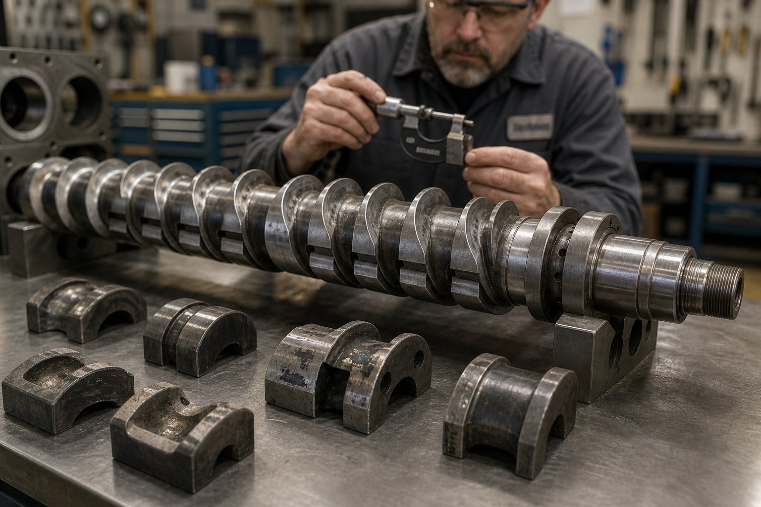
Regular inspection, ideally monthly for high-wear applications, catches degradation early. Measuring screw element diameters with a micrometer and comparing them against original drawings takes minutes but can prevent the cascading failures that turn a worn flight tip into a flooded vent, a torque alarm, and ultimately an unplanned shutdown that costs far more than a set of replacement elements ever would.
Diagnosing and fixing problems is essential, but retaining the technical vocabulary to communicate those problems precisely, whether to your maintenance team, equipment supplier, or a replacement parts vendor, requires a shared language. That's where a consolidated glossary and knowing where to find expert support make the difference between a quick resolution and a drawn-out guessing game.
Essential Twin Screw Extruder Terminology and Technical Support Resources
Precise language prevents expensive miscommunication. When you call a supplier about a torque alarm or email your engineering team about a vent-flooding issue, using the correct terminology turns a confusing back-and-forth into a focused, productive conversation. The glossary below consolidates the terms you'll encounter most frequently across spec sheets, technical manuals, and process reports, serving as the kind of twin screw extruder terminology glossary pdf that most engineers wish they had bookmarked years ago.
Essential Twin Screw Extrusion Terminology Glossary
| Term | Definition |
|---|---|
| L/D Ratio | The process length of the extruder barrel divided by the screw diameter. A higher L/D ratio (e.g., 48:1) provides more functional zones for feeding, mixing, venting, and pressurization compared to a shorter machine (e.g., 28:1). |
| Specific Energy Input (SEI) | The mechanical energy consumed per kilogram of material processed, expressed in kW·hr/kg. Calculated from motor power, torque percentage, RPM ratio, gearbox efficiency, and throughput. A consistent SEI across production runs indicates process stability. |
| Free Volume | The open volume available inside the barrel for material, determined by screw channel depth and flight geometry. Critical for processing low-bulk-density feedstocks like recycled flake, wood fiber, or expanded microspheres. |
| Self-Wiping | The geometric property of intermeshing co-rotating screws where one screw's flight continuously sweeps material off the other screw's surface. This action eliminates dead zones, prevents material stagnation, and ensures a narrow residence time distribution. |
| Residence Time Distribution (RTD) | A statistical measure of how uniformly material particles spend time inside the extruder. A narrow RTD means every particle exits at roughly the same "age," ensuring consistent thermal and shear history across the entire output. |
| Specific Throughput | Output in kg/hr divided by screw speed in RPM. This ratio indicates the degree of barrel fill and serves as a practical scaling tool when transferring processes between machines or adjusting rates on the same extruder. |
| Torque Density | Maximum torque per shaft divided by the cube of the centerline distance between screw axes (Nm/cm³). The most important single metric for comparing gearbox performance across manufacturers and machine sizes. |
| Do/Di Ratio | The ratio of screw outer diameter to inner (root) diameter. A larger ratio increases free volume and throughput capacity but reduces shaft stiffness and torque transmission capability. Modern designs typically range from 1.55 to 1.71. |
Consider this table your quick-reference twin screw extruder technical reference pdf substitute. Print it, save it to your phone, or pin it next to the extruder HMI. When a colleague asks what torque density actually means during a spec sheet review, you'll have the answer in seconds.
Where to Find Technical Support and Screw Barrel Solutions
Glossaries and guides get you far, but certain situations demand hands-on expertise: sourcing replacement screw elements matched to a specific machine model, diagnosing an unusual wear pattern, or evaluating screw barrel compatibility for a new formulation. Knowing where to turn saves days of searching and prevents costly sourcing mistakes. The following twin screw extruder resources and support pdf alternatives cover the full spectrum of technical needs:
- Screw barrel suppliers with application support — NANHAIYA's Plastic Extruder Machine and Screw Barrel Support connects extrusion manufacturers, recycling plants, and technical teams with compatible screw and barrel components for pipe, profile, sheet, pelletizing, recycling, and general plastic processing lines. Having a reliable component partner who understands machine-specific requirements reduces lead times and ensures dimensional accuracy on replacement parts.
- Manufacturer technical manuals — OEM documentation from your extruder's manufacturer remains the authoritative source for torque limits, recommended screw element materials, gearbox maintenance schedules, and barrel alignment procedures. Request the full technical manual, not just the operator's guide, when commissioning new equipment.
- Industry textbooks — Klemens Kohlgruber's Co-Rotating Twin-Screw Extruders provides deep engineering coverage of screw geometry, flow modeling, and scale-up methodology. For a broader perspective, Harold Giles's Extrusion: The Definitive Processing Guide and Handbook covers both single- and twin-screw systems with practical troubleshooting emphasis.
- Technical conference proceedings — SPE ANTEC, the Polymer Processing Society annual meeting, and Compounding World conferences publish peer-reviewed papers on screw design optimization, novel element geometries, and process parameter studies that push beyond what textbooks cover.
- Equipment supplier engineering teams — Most major extruder manufacturers offer process trials, screw configuration consulting, and on-site technical support. Leverage these services during new product development or when troubleshooting persistent quality issues that internal adjustments haven't resolved.
The most effective technical teams don't rely on a single resource type. They combine supplier expertise for component-level questions, textbooks for foundational understanding, and conference literature for emerging techniques, building a layered knowledge base that handles everything from routine maintenance decisions to complex process development challenges. This guide was designed to serve as the connective layer between those resources, giving you the vocabulary, diagnostic logic, and specification literacy to ask the right questions and evaluate the answers with confidence.
Frequently Asked Questions About Twin Screw Extruders
1. What is the difference between co-rotating and counter-rotating twin screw extruders?
Co-rotating twin screw extruders have both screws turning in the same direction with fully intermeshing, self-wiping geometry, making them ideal for high-speed compounding, masterbatch production, and reactive extrusion due to their excellent dispersive and distributive mixing. Counter-rotating extruders spin screws in opposite directions, creating a calendering effect that generates high pressure with lower shear. This gentler processing character makes counter-rotating designs the standard choice for thermally sensitive materials like rigid PVC in pipe and profile extrusion. The configuration you choose fundamentally determines shear intensity, pressure-building capability, and the range of materials you can process effectively.
2. How do you read and compare twin screw extruder specification sheets?
Focus on five interconnected parameters rather than any single number. Screw diameter defines machine size class and throughput scale. L/D ratio indicates available process length for configuring functional zones, with ratios of 40:1 to 52:1 offering the most flexibility for complex processes. Torque density, expressed in Nm/cm3, is the most critical performance indicator for comparing gearboxes across manufacturers, as higher values enable processing of high-viscosity melts and heavily filled compounds. Free volume determines intake capacity for low-bulk-density feedstocks, and the Do/Di ratio balances channel depth against shaft strength. Always verify whether a manufacturer's published L/D includes or excludes the die adapter, as this can inflate the number without adding usable process length.
3. What causes vent flooding in a twin screw extruder and how do you fix it?
Vent flooding occurs when molten material extrudes through vent ports, and it always results from excessive material in the vent zone relative to the screw's forward conveying capacity. The three most common triggers are an incorrect screw-speed-to-feed-rate ratio that disrupts fill-level balance, worn or improperly positioned sealing elements upstream of the vent that fail to maintain a full melt seal, and screw speed set too high relative to feed rate. To resolve it, adjust the feed-rate-to-RPM ratio to restore proper fill levels, inspect and replace worn reverse kneading blocks or reverse conveying elements upstream of the vent, and ensure the vent-zone screw elements maintain their original dimensional tolerances.
4. What role do kneading blocks play in twin screw extruder screw design?
Kneading blocks are the primary mixing instruments in a twin screw extruder, consisting of stacked discs offset at defined stagger angles on the splined shaft. Three design variables control their behavior: disc width, stagger angle, and the number of discs per block. Narrow discs with high stagger angles (such as 90 degrees) deliver aggressive dispersive mixing that fractures pigment agglomerates and deagglomerates fillers, while wide discs with low stagger angles (such as 30 degrees) provide gentler distributive blending suited for color masterbatch or fiber-reinforced compounds where maintaining filler morphology matters. Proper placement within the screw configuration's functional zones, such as melting, primary mixing, or homogenization, determines whether the blocks improve product quality or cause thermal degradation and excessive torque demand.
5. Where can I find replacement screw barrels and technical support for twin screw extruders?
Reliable sourcing for replacement screw barrels requires suppliers who understand machine-specific dimensional requirements and metallurgical specifications. NANHAIYA's Plastic Extruder Machine and Screw Barrel Support at nhyscrews.com connects extrusion manufacturers, recycling plants, and technical teams with compatible screw and barrel components for pipe, profile, sheet, pelletizing, and recycling lines. Beyond component suppliers, leverage your extruder OEM's full technical manual for torque limits and maintenance schedules, consult industry textbooks like Kohlgruber's Co-Rotating Twin-Screw Extruders for foundational engineering knowledge, and review SPE ANTEC or Compounding World conference proceedings for emerging screw design techniques and process optimization studies.
Written by
Nanhaiya Technical Team
Zhoushan Nanhaiya Plastic Machinery Co., Ltd.
The Nanhaiya technical team supports screw and barrel manufacturing projects through application review, technical communication, custom manufacturing coordination, and production and quality control.
Discuss Your Application
Related Articles
More insights on screw barrel technology and plastics processing.

What Nobody Tells You About Screw Barrel For Plastic Machine Design
Oct 10, 2026
Learn how screw barrel for plastic machine design affects melt quality, throughput, and wear life. Covers geometry, resin matching, troubleshooting, and sourcing.
Read Article
Single Screw Extruder for Sheet: Stop Guessing, Start Specifying
Oct 9, 2026
Learn how to specify a single screw extruder for sheet production. Covers screw geometry, resin-specific processing, troubleshooting, and maintenance best practices.
Read Article
PE Pipe Extruder Machine: What Datasheets Won't Tell You
Oct 9, 2026
Learn how a PE pipe extruder machine works, key specs explained, material grade selection, maintenance tips, and buyer guidance beyond the datasheet.
Read ArticleLooking for something else?
Search by material, symptom or product and jump straight to the relevant page.
These are navigation suggestions based on keyword matching — not a quotation, not a delivery commitment, and not a substitute for engineering review. Final specification is confirmed by our engineers against your drawings and processed material.
Need help with screw barrel selection?
Share your machine model, processed material and application. Our team can help with pricing and technical support.