

What Twin Screw Extruder Parts Are and Why Every Component Matters
What Are Twin Screw Extruder Parts
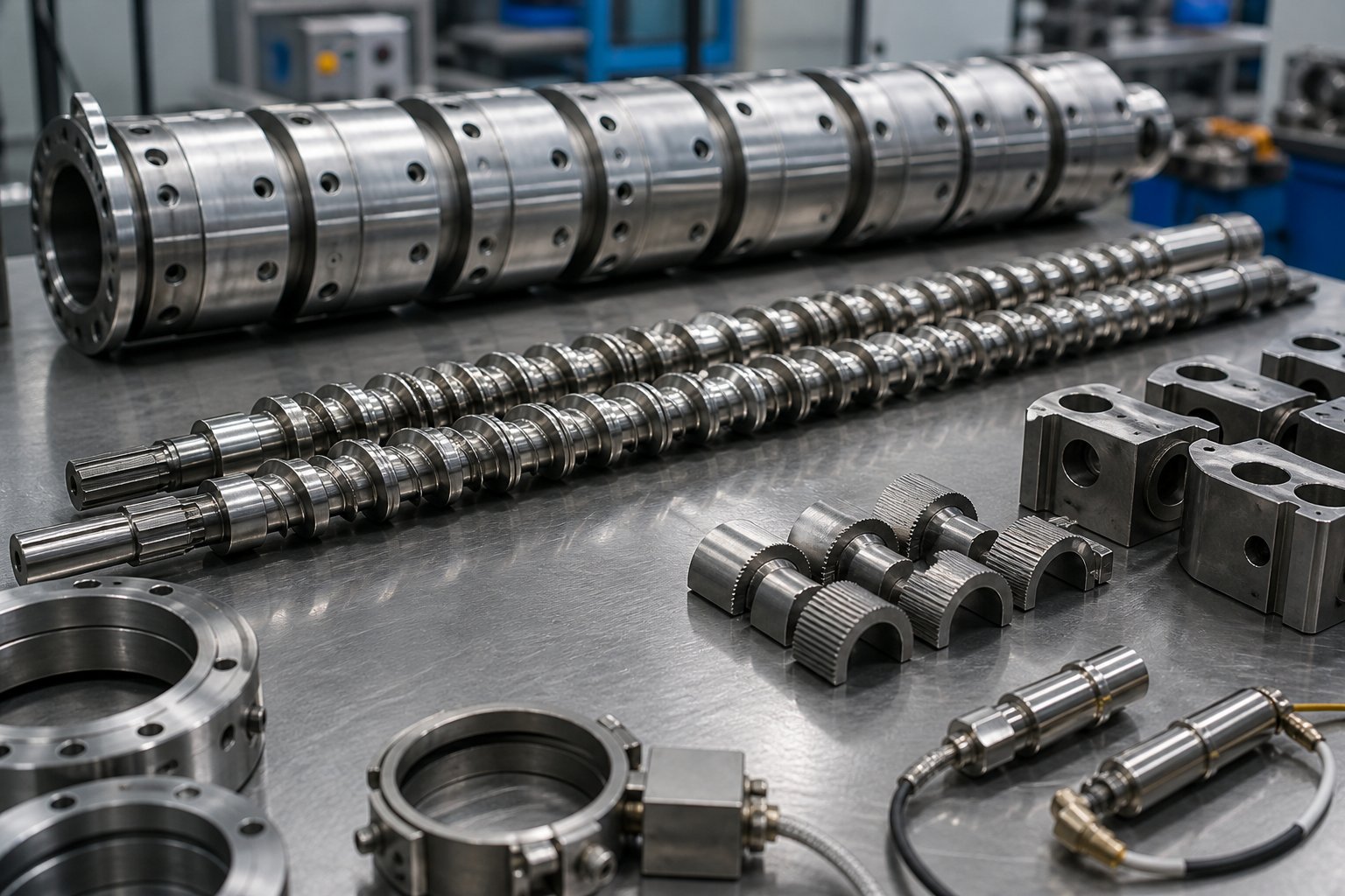
Twin screw extruder parts are the individually engineered, replaceable components that make up a modular extrusion system. These components include the intermeshing screw elements, segmented barrel sections, gearbox and drive assembly, heating and cooling systems, feeding mechanisms, venting ports, die heads, and downstream equipment such as pelletizers and screen changers. Each part serves a distinct processing function, and together they form a continuous system that melts, mixes, conveys, and shapes materials with high precision.
What makes this equipment fundamentally different from simpler single-screw machines is its modular architecture. Rather than being manufactured as a single fixed unit, a twin screw extruder is assembled from interchangeable segments. Screw elements slide onto splined shafts in a deliberate sequence. Barrel sections bolt together in series, each one potentially configured for a different task. Even the feeding system, temperature zones, and die assembly can be swapped or reconfigured without replacing the entire machine.
A twin screw extruder is a modular machine where every part's geometry, material grade, and position along the process length directly controls processing performance, product quality, and equipment longevity.
This modularity is the reason a parts-level understanding matters so much. The screw shape, diameter, pitch, and element arrangement define throughput and mixing capability, while the barrel manages temperature, pressure, and material containment. The gearbox synchronizes screw rotation and regulates torque delivery. Downstream components shape the final product. Change one element in this chain, and you alter the entire process outcome.
Why a Parts-Level Understanding Matters
Imagine a compounding line producing off-spec pellets. Is the problem a worn kneading block, an oversized barrel bore, a failing thermocouple, or a dull pelletizer blade? Without a clear understanding of what each part does and how it interacts with its neighbors, troubleshooting becomes guesswork. Maintenance engineers need this knowledge to diagnose wear patterns and schedule replacements before failures cascade. Process engineers rely on it to optimize screw profiles and barrel configurations for new formulations. Procurement teams depend on it to specify correct material grades, tolerances, and geometries when sourcing replacements.
Machine performance, product quality, and production uptime all hinge on correct part specification. A single mismatched screw element or a barrel segment with excessive bore wear can degrade mixing efficiency, introduce contamination, or cause costly unplanned downtime. The sections that follow provide a systematic walkthrough of every major component category, starting from the heart of the machine, the screw elements, and working outward through barrels, gearboxes, auxiliary systems, and the metallurgy that determines how long each part survives in service.
Screw Element Types and the Geometry That Drives Processing
Every twin screw extruder builds its processing capability from a surprisingly small family of screw elements. These elements slide onto splined shafts in a precise order, and the combination you choose determines whether a material melts gently or aggressively, mixes uniformly or poorly, and exits the die at the right temperature and pressure. Understanding twin screw extruder screw element types is the single most important step toward mastering both process design and maintenance diagnostics.
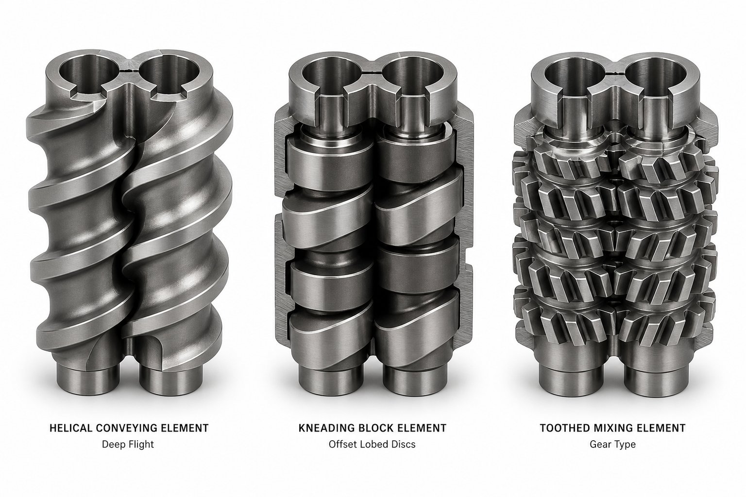
Three primary element families handle the work: conveying elements, kneading blocks, and specialized mixing elements. Each one manipulates the material differently, and each has distinct geometric parameters that control its behavior. Let's break them down.
Conveying Elements, Kneading Blocks, and Mixing Elements
Conveying elements are the workhorses of material transport. They feature helical flights wrapped around the screw root, and their deeper channel geometry enables efficient movement of material from one extruder zone to the next without applying excessive shear. You'll find forward-flight conveying elements (designated with "R" for right-hand rotation) throughout the feed zone and between functional sections, where their job is to push material downstream and build moderate pressure. Research from NC State Extension confirms that deeper channel screws provide better conveying with higher screw volume, while channel depth decreases progressively from conveying to compression to metering zones.
Reverse-flight conveying elements (designated "L" for left-hand rotation) do the opposite. They push material backward, creating a restrictive barrier that increases residence time and pressure upstream. This backflow effect is essential for creating sealed zones ahead of vent ports and for ensuring that the material spends enough time in mixing sections to achieve uniform composition.
Kneading blocks are where the real mixing happens. Instead of continuous helical flights, kneading blocks consist of a series of individual lobed discs stacked at offset angles along the shaft. The offset between adjacent discs, known as the stagger angle, is the primary variable that determines how aggressively the element mixes. A numerical simulation study published in Foods demonstrated that the misalignment angle between discs greatly improves the mixing and shear degree of fluid while weakening conveying capacity. Forward-staggered kneading blocks (e.g., KP 45/5/20 R) provide moderate mixing with some forward conveying action. Neutral stagger angles halt forward conveyance entirely, focusing all energy on the material and increasing residence time. Reverse-staggered kneading blocks push material backward, creating maximum restriction and the highest shear intensity.
The width of individual kneading discs matters, too. Wider discs promote dispersive mixing, which breaks down agglomerates and particle clusters by applying strong shear stress. Narrower discs favor distributive mixing, which spreads the dispersed phase evenly throughout the matrix without necessarily breaking particles apart. As Leistritz Extrusion's technical literature puts it: narrow kneading elements facilitate high division rate mixing with minimal extensional effects, while wider elements accentuate extensional mixing and planar shear.
Specialized mixing elements round out the toolkit. Toothed mixing elements (sometimes called ZME or gear-type elements) feature interlocking teeth rather than continuous flights or offset discs. Their geometry splits and recombines the material stream repeatedly, delivering excellent distributive mixing with minimal shear input. This makes them particularly useful for blending shear-sensitive materials or for achieving fine dispersion without overheating the compound. Other specialized designs like TME (turbine mixing elements) serve niche functions in reactive extrusion and devolatilization sealing.
| Element Type | Primary Function | Key Geometry Parameters | Typical Position in Profile |
|---|---|---|---|
| Forward Conveying Element | Material transport and moderate pressure buildup | Pitch, flight depth, helix angle | Feed zone, between mixing sections, discharge zone |
| Reverse Conveying Element | Backflow restriction and sealing before vent ports | Pitch, flight depth, element length | Upstream of vent openings, after mixing zones |
| Forward Kneading Block | Melting and moderate dispersive/distributive mixing | Stagger angle, disc width, number of discs | Melting zone, primary mixing zone |
| Neutral Kneading Block | Intensive mixing with maximum residence time | 90-degree stagger, disc width, number of discs | High-shear mixing zone |
| Reverse Kneading Block | Maximum shear and flow restriction | Reverse stagger angle, disc width, number of discs | Before devolatilization vents, end of mixing zone |
| Toothed Mixing Element (ZME) | Distributive mixing with low shear | Number of teeth, number of tooth rows, element length | After initial melting, blending zones for sensitive materials |
Design Parameters That Control Performance
Sounds complex? The good news is that all these element types are governed by a relatively small set of geometric parameters. Understanding the relationships between them is what separates a well-optimized screw profile from one that produces off-spec material or excessive wear.
L/D ratio (length-to-diameter ratio) defines the overall processing length of the extruder relative to its screw diameter. A higher L/D ratio provides more barrel length for sequencing different functional zones, feeding, melting, mixing, venting, and pressure buildup, giving engineers greater flexibility to handle complex formulations. Most modern co-rotating twin screw extruders operate at L/D ratios ranging from roughly 32:1 to 48:1 or higher, depending on the application's complexity. The twin screw extruder L/D ratio explained in simple terms is this: more length means more room for process steps, but also longer residence time, which can be harmful to heat-sensitive materials.
Pitch is the axial distance between two consecutive flights on a conveying element. Increasing the pitch increases the conveying rate per screw revolution, which means material moves faster through that zone. But there's a trade-off. The NC State Extension publication notes that increasing pitch also increases shear input in the raw material. Numerical simulations from the China Agricultural University study confirmed that reducing pitch creates more pronounced periodicity in the shear rate fluctuation, improving shear stability, while larger pitches produce stronger pumping capability and pressure buildup.
Flight depth (or channel depth) is the distance from the top of the screw flight to the root diameter. Deeper flights create more free volume inside the screw channel, allowing higher throughput and longer material residence. Shallower flights compress the material into a thinner layer, increasing shear rate and pressure generation. This is why feed zones use deep-flighted elements, think maximum intake capacity, while metering zones near the die use progressively shallower geometry to build discharge pressure.
Stagger angle on kneading blocks is arguably the most influential single parameter in any twin screw profile. When the lobed discs of a kneading block are offset at a narrow forward angle, the element retains some conveying action while gently mixing. As the stagger angle widens toward 90 degrees (neutral), conveying drops to zero and mixing intensity increases dramatically because the material is no longer being pushed forward and instead receives pure energy input. The kneading block stagger angle effect extends beyond mixing quality. It directly impacts melt temperature, torque demand, and the risk of polymer degradation. The same simulation study found that kneading blocks with interleaved discs generated increased backflow between adjacent channels, extending the residence time distribution and improving particle dispersion, but also reducing the outflow velocity significantly compared to conveying elements.
OD/ID ratio (Outside Diameter to Inside Diameter) is another critical specification that determines available free volume at a given screw diameter. A higher OD/ID ratio yields more free volume per unit of screw length, which directly translates to higher potential throughput for volume-limited processes. Leistritz, for example, highlights that comparing a 1.55 OD/ID ratio machine to a 1.66 OD/ID machine can yield a 30% throughput increase, all else being equal.
None of these parameters exist in isolation. Selecting a deeper flight depth increases free volume but may reduce shear intensity. Widening a kneading block stagger angle boosts mixing but risks overheating shear-sensitive polymers. Shortening pitch improves shear stability but slows material transport. Every parameter choice reflects a deliberate engineering trade-off, dictated by the specific polymer or compound being processed, its thermal sensitivity, its viscosity behavior, and the quality requirements of the final product.
These geometric details matter far beyond initial machine setup. As screw elements wear in service, flight tips lose height, kneading disc edges round off, and the precise clearances that define mixing behavior degrade. The barrel segments that house these elements play an equally critical role in maintaining those clearances, and their design is just as varied and purposeful as the screws themselves.
Barrel Segment Types and How Each One Shapes the Process
Screw elements define what happens to the material, but the barrel segments surrounding them determine where and how those operations take place. Imagine trying to vent moisture from a polymer melt through a fully enclosed steel tube. It simply would not work. Different processing stages demand different barrel designs, and understanding twin screw extruder barrel segment types is essential for anyone configuring, maintaining, or troubleshooting a compounding line.
Unlike single-screw extruders, where the barrel is typically one continuous piece, twin screw machines use segmented barrel sections that bolt together in series. Most manufacturers supply these segments in lengths of four, five, or six diameters, and each section is independently heated and cooled for precise temperature control. Every section features the characteristic figure-8 bore through which the two intermeshing screws rotate. The real differentiation lies in what else each barrel section provides beyond that shared bore geometry.
Solid Feed Barrels vs Vented Barrels vs Side-Feed Barrels
Five primary barrel segment types handle the full range of processing tasks along the extruder length. Each one serves a specific function that cannot be replicated by the others.
- Closed (Solid) Barrels: Fully enclosed on all sides with only the figure-8 screw bore running through the center. These segments provide maximum temperature control via surrounding heater bands and cooling channels, and they maintain full pressure containment. They are the most common barrel type, used in melting zones, mixing zones, and pressure-buildup zones where no material addition or volatile removal is needed.
- Open-Top Feed Barrels: Feature an opening at the top of the barrel through which raw materials are gravity-fed or metered onto the screws. The feed barrel almost always occupies the first position in the barrel layout. For low-bulk-density powders that entrain significant air, a second open barrel can be placed just upstream in a back-vent arrangement, allowing trapped air to escape out of Barrel 1 while powder feeds into Barrel 2.
- Vented Barrels: Open barrel sections positioned downstream specifically for removing volatiles. A vented barrel for devolatilization extrusion may operate at atmospheric pressure or connect to a vacuum pump for more aggressive volatile extraction. These ports remove moisture, solvents, monomers, and trapped air before the melt reaches the die. Kenneth W. Russell, a veteran compounding consultant, recommends placing the vacuum vent at least two barrel sections upstream of the die to prevent molten polymer from backing up into the vent port during pressure fluctuations.
- Side-Feed Barrels: Incorporate a secondary figure-8 bore on the side of the main barrel to accept a twin-screw side stuffer. A side feed barrel on a twin screw extruder allows downstream addition of fillers, glass fibers, mineral additives, or secondary polymers directly into the melt stream after initial melting and mixing are complete. This prevents shear-sensitive additives from being degraded by the full melting section. A standard open barrel is typically placed just upstream of the side feeder to vent entrained air. Some manufacturers offer combination barrels (combi-barrels) that integrate the side-feed port and upstream vent into a single compact section.
- Liquid-Injection Barrels: Feature small injection ports, often fitted with nozzles or injection valves, designed for introducing plasticizers, reactive agents, peroxides, or other liquid additives at precise locations along the process length. These barrels allow controlled metering of liquids into the melt at the exact point where they are needed for the reaction or blend.
How Barrel Configuration Shapes the Process
The power of segmented barrel design lies in sequencing. By arranging different barrel types in a deliberate order, engineers create distinct functional zones along the extruder, each one dedicated to a specific unit operation. A typical compounding layout might begin with an open feed barrel, followed by several closed barrels for solids conveying and polymer melting, a combi-barrel at barrel position four or five for side feeding of additives, more closed barrels for continued mixing, a vented barrel near the end for devolatilization, and a final closed section for pressure buildup before the die.
Changing even a single barrel segment can reshape the entire process. Swapping a closed barrel for a vented barrel opens a devolatilization zone that did not previously exist. Relocating a side-feed barrel further downstream gives the polymer more residence time to fully melt before fillers are introduced, reducing unmelted polymer inclusions in the final compound. This configurability is what allows the same base machine to handle everything from mineral-filled polyolefins to reactive polyurethane formulations.
Barrel bore tolerances are a less visible but equally critical factor. The inner diameter of each barrel segment must maintain tight clearance with the outer diameter of the screw elements rotating inside it. Extruder barrel bore tolerance and clearance directly affect mixing efficiency, self-wiping performance, energy consumption, and product contamination risk. As barrel bores enlarge through abrasive wear, the gap between screw tip and barrel wall widens. This reduces the shear applied to the material in that zone, decreases self-wiping efficiency (allowing material to stagnate and degrade), and lowers the pressure-generating capability of the screws. On production-scale machines, even fractions of a millimeter of bore enlargement can measurably degrade output quality and throughput stability.
This sensitivity to clearance is precisely why barrel material selection and surface treatments matter so much. The metallurgy behind both screws and barrels determines how long these tight tolerances survive under real processing conditions, and it deserves its own detailed examination.
Gearbox, Drive System, and Essential Auxiliary Components
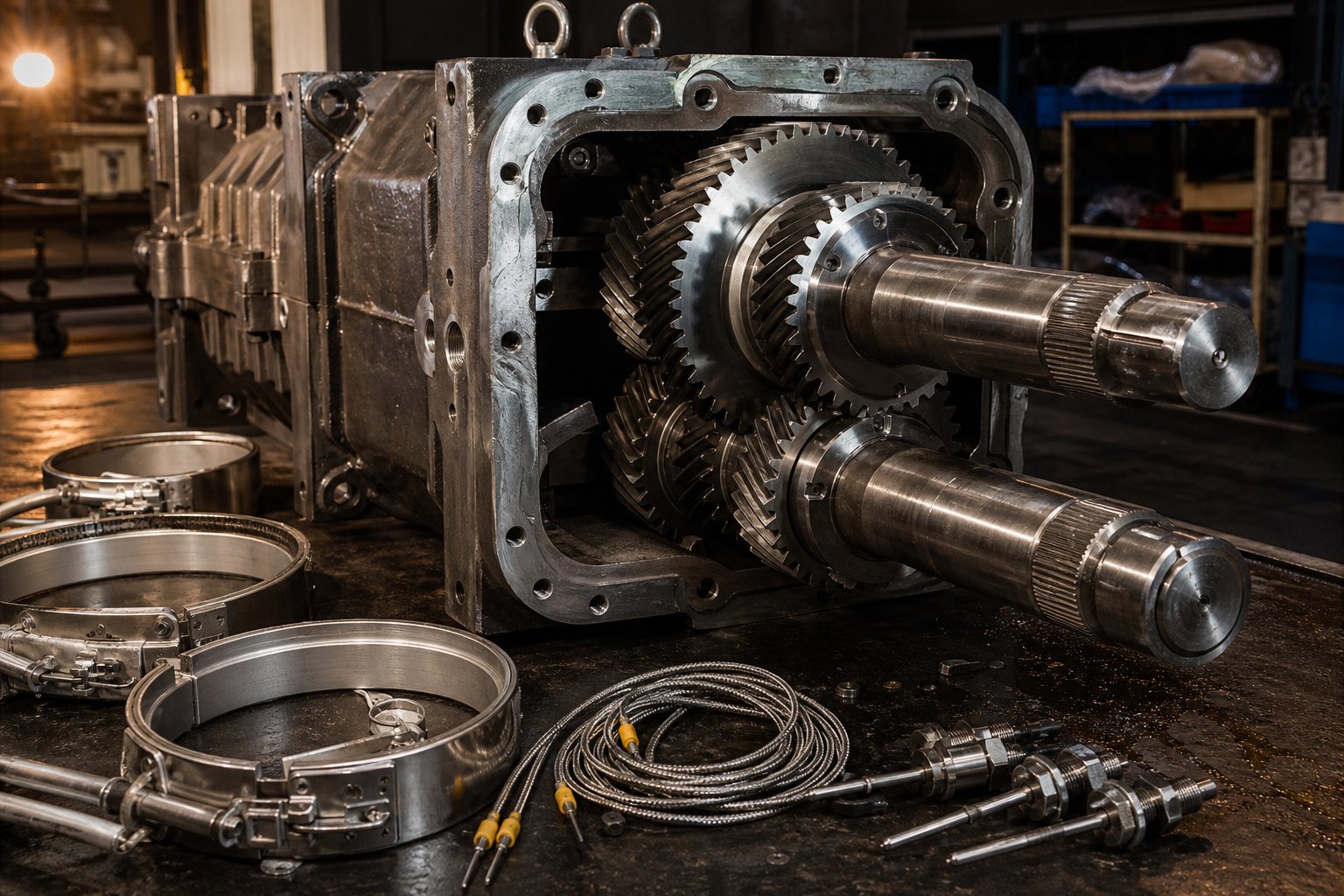
Screws and barrels shape the material, but nothing turns without the gearbox and drive system delivering precisely controlled mechanical energy. The gearbox is arguably the most expensive single component in a twin screw extruder, and its engineering constraints ripple outward into every aspect of machine performance, from maximum throughput to long-term reliability. Yet most discussions of twin screw extruder parts skip past it entirely. That's a costly oversight.
Gearbox Architecture and Torque Distribution
The fundamental challenge of a twin screw extruder gearbox is deceptively simple: split motor torque evenly between two closely spaced, parallel output shafts. In practice, this is one of the hardest problems in industrial power transmission. The two screw shafts must rotate at identical speeds with precise angular synchronization, and they must do so while absorbing enormous axial thrust loads generated by back pressure from the die.
Think about the geometry for a moment. The center-to-center distance between the two output shafts is dictated by the screw diameter, which is relatively small. You need to fit gears, bearings, and lubrication passages into that tight envelope while transmitting thousands of Newton-meters of continuous torque. The gear on the output shaft closest to the motor receives torque directly, but the gear on the second shaft, the one further away, must receive an equal share through an additional gear mesh. As Cowin Extrusion's technical literature explains, the B-axis gear in a traditional parallel three-axis layout is inherently smaller due to center distance constraints, making it the torque-capacity bottleneck of the entire gearbox.
This bottleneck is why torque density, measured in Nm/cm3, has become the defining specification for twin screw extruder gearboxes. Torque density expresses how much torque the gearbox can deliver relative to the screw cross-sectional area it drives. Higher torque density means more energy reaches the screws per unit of available space. Modern high-performance machines achieve torque densities of 18 Nm/cm3, a roughly 30% increase over previous-generation designs. This leap enables processing of highly filled and high-viscosity compounds, such as glass-fiber-reinforced polyamide, that would have been torque-limited on older equipment.
The relationship between screw diameter, shaft center distance, and maximum allowable torque follows a cube law: doubling the screw diameter roughly octuples the torque requirement. Meanwhile, increasing the L/D ratio or screw speed multiplies torque demand further. A practical rule of thumb from industry experience is to run the gearbox at no more than 80% of its continuous-duty torque rating and 80% of maximum speed, preserving headroom for cold-start transients and process variations. Peak startup torque can exceed steady-state running torque by 20-40%, and undersizing the gearbox for these spikes is one of the most common specification errors.
Axial thrust is the other critical load the gearbox must absorb. As pressurized melt pushes against the die, it drives the screws rearward into the gearbox thrust bearings. On large production machines, these thrust forces can reach up to 3,400 kN. Thrust bearing fatigue, not gear tooth failure, is often the life-limiting factor. Specifying adequate thrust bearing capacity and maintaining proper lubrication and cooling are essential to reaching the target bearing life of approximately 12,000 hours under normal operating conditions.
Auxiliary Components Beyond Screws and Barrels
Screws, barrels, and gearboxes attract the most engineering attention, but a twin screw extruder relies on a much broader ecosystem of auxiliary parts. These components handle everything from shaping the final product to monitoring process conditions in real time. Many of them wear faster than core components and require more frequent replacement, yet they rarely appear in spare parts planning discussions.
Here is a practical twin screw extruder auxiliary parts list covering the most critical items:
- Die Heads: Mounted at the extruder discharge, the die shapes the melt stream into strands, sheets, profiles, or other geometries. Die bore wear directly affects product dimensional consistency and surface quality.
- Screen Changers: Positioned between the extruder and the die, screen changers filter contaminants and unmelted particles from the melt. Screen packs and breaker plates require routine replacement as they accumulate debris and restrict flow.
- Pelletizing Systems: Strand pelletizers pull melt strands through a water bath and chop them into pellets using rotating blades. Underwater pelletizers cut the melt directly at the die face submerged in process water. In both systems, pelletizer blade condition governs pellet size uniformity and cut quality.
- Heater Bands: Ceramic or mica-insulated electric heaters clamped around each barrel segment provide the thermal energy needed for melting and maintaining target zone temperatures. Burned-out or degraded heater bands cause temperature instability and uneven melt quality.
- Cooling Channels: Internal or external cooling circuits, typically using water or thermal oil, remove excess heat from barrel zones where shear heating would otherwise overshoot the target temperature. Clogged or scaled cooling passages reduce heat removal capacity.
- Thermocouples: Temperature sensors inserted into each barrel zone provide the feedback that temperature controllers rely on to regulate heater bands and cooling valves. A malfunctioning thermocouple can cause an entire zone to overheat or underheat without any visible alarm until product quality degrades.
- Gravimetric and Volumetric Feed Systems: Feeders meter raw materials into the extruder at controlled rates. Feed accuracy directly determines product composition consistency, especially in formulations with multiple components dosed at precise ratios.
- Coupling and Thrust Collar Assemblies: Mechanical connections between the motor, gearbox, and screw shafts transmit torque and absorb misalignment. Worn couplings introduce vibration and accelerate bearing wear throughout the drivetrain.
What makes these extruder die head and pelletizer parts so important is their position at the boundaries of the process. A perfectly compounded melt means nothing if the die is worn and produces inconsistent strand diameters, or if dull pelletizer blades generate excessive fines and angel hair. Similarly, a thermocouple that reads 15 degrees low will silently drive the controller to overheat its zone, potentially degrading the polymer before anyone notices a product quality shift.
A twin screw extruder is a system, not a collection of independent parts. Upstream or downstream component failures propagate through the entire process chain, and the weakest auxiliary part often limits overall line performance.
This systems-level perspective becomes especially important when you consider the fundamental design differences between the two main categories of twin screw extruders. Co-rotating and counter-rotating configurations don't just process material differently; they use fundamentally different parts, from screw element geometry to barrel bore profiles, and confusing the two can lead to expensive mistakes.
Co-Rotating vs Counter-Rotating Twin Screw Part Differences
Here is a question that trips up even experienced buyers and maintenance teams: can you use screw elements from a co-rotating twin screw extruder on a counter-rotating machine? The short answer is absolutely not. While both configurations share the label "twin screw," the parts inside them are engineered around fundamentally different rotational mechanics, flow geometries, and clearance requirements. Confusing the two doesn't just cause a poor fit; it risks catastrophic mechanical failure.
Understanding co-rotating vs counter-rotating twin screw parts at the component level is critical for anyone specifying replacements, designing screw profiles, or evaluating a machine for a new application. The differences start with how the screws interact and ripple outward into barrel geometry, element design, gearbox architecture, and even wear patterns.
How Co-Rotating and Counter-Rotating Designs Differ at the Part Level
In a co-rotating twin screw extruder, both screws turn in the same direction. This rotation allows a fully intermeshing geometry where each screw flight wipes the surface of the adjacent screw. The result is what engineers call self-wiping twin screw element geometry, originally described as the Erdmenger profile. Material is forcibly handed off from one screw to the other at the intermeshing zone, creating a figure-8 flow path that minimizes dead zones, suppresses stagnation, and keeps the residence time distribution narrow. As Technovel Corporation explains, this self-wiping action plays a particularly important role during reactive extrusion and the processing of materials sensitive to thermal history.
Self-wiping geometry demands extremely tight clearances between the screw element outer diameter and the adjacent screw root, typically on the order of fractions of a millimeter. Every element on one screw must be precisely matched in profile, length, and position to its counterpart on the other screw. Swap an element on one shaft without making the identical change on the other, and you lose the intermeshing relationship that defines the machine's mixing capability.
Counter-rotating extruder screw elements operate on a completely different principle. When the screws rotate in opposite directions, material at the intermeshing zone is drawn inward and compressed rather than being wiped from one screw to the other. This creates what is known as a calendering effect, similar to how two rollers squeeze material in a calender stack. The screws form enclosed C-shaped chambers that trap material and advance it forward through positive displacement. The Nastaj and Wilczynski research published in Polymers confirms that material transport in counter-rotating machines relies on this positive displacement mechanism, with several leakage flows, calendering flow, flight flow, pressure flow, and side flow, determining how much material escapes past the intermeshing region.
This mechanical difference directly shapes the parts. Co-rotating screw elements feature the characteristic bilobal cross-section optimized for self-wiping. Counter-rotating elements use different flight geometries sized for the calendering nip rather than for surface wiping. The barrel bore in both cases has a figure-8 (bilobal) cross-section, but the center distance between bores, the overlap geometry, and the bore tolerances differ between the two configurations because the forces acting on the barrel wall are distributed differently.
Even the gearbox is a fundamentally different piece of equipment. A co-rotating gearbox synchronizes two shafts spinning in the same direction and typically uses a gear train that splits torque through parallel paths. A counter-rotating gearbox must drive two shafts in opposite directions, requiring a different gear mesh arrangement and different bearing configurations to handle the distinct thrust load characteristics.
Part Selection Implications for Each Configuration
Why does this matter in practice? Because co-rotating twin screw extruder applications and counter-rotating applications demand different parts, different process strategies, and different spare parts inventories.
Co-rotating machines dominate compounding, polymer alloying, and reactive extrusion. Their intense shear fields, created both between the screws and between the screws and barrel, combined with the elongational flow contributed by kneading blocks, produce the complex deformation history needed to break up filler agglomerates, regulate phase morphology, and promote mass transfer in chemical reactions. The free configurability of screw elements on co-rotating machines allows engineers to place energy input precisely where it is needed along the barrel length.
Counter-rotating machines excel with thermally sensitive materials. Rigid PVC, for example, has a low decomposition temperature and poor melt flow. The high-shear environment of a co-rotating machine can push PVC past its degradation threshold. Counter-rotating extruders, by contrast, process PVC at high fill levels and low screw speeds, keeping shear stress and shear-induced heat generation low while using the calendering effect for gentle dispersive mixing of additives. This is why counter-rotating machines remain the standard for PVC pipes, sheets, and profile extrusion products.
The critical takeaway for maintenance and procurement teams is straightforward: parts are not interchangeable between these configurations. Ordering a kneading block designed for a co-rotating machine and attempting to install it on a counter-rotating extruder will not work mechanically, and even if forced, would destroy the process dynamics the machine depends on. Screw elements, barrel segments, gearboxes, and even shaft spline profiles differ between the two designs. When sourcing replacements, you must specify not only the machine make and model but also the rotation configuration.
| Feature | Co-Rotating | Counter-Rotating |
|---|---|---|
| Self-Wiping Capability | Full self-wiping; each screw cleans the other continuously | No self-wiping; material is compressed in the nip zone via calendering |
| Typical Screw-to-Screw Clearances | Very tight; fractions of a millimeter to maintain Erdmenger profile | Wider clearances acceptable; positive displacement reduces sensitivity |
| Shear Intensity at Intermeshing Zone | High shear stress; intense dispersive and distributive mixing | Lower shear stress; gentle compressive and elongational deformation |
| Dominant Applications | Compounding, polymer alloys, reactive extrusion, nanocomposites | PVC pipe and profile extrusion, thermally sensitive polymers |
| Element Interchangeability | Not interchangeable with counter-rotating elements | Not interchangeable with co-rotating elements |
| Gearbox Design | Same-direction output shafts; parallel torque splitting | Opposite-direction output shafts; reverse gear mesh required |
These configuration-level differences in part design raise an equally important question: what materials should those parts be made from? A co-rotating machine processing glass-fiber-filled nylon at high shear endures completely different wear conditions than a counter-rotating extruder running unfilled PVC powder at low speed. The metallurgy and surface treatments chosen for screws and barrels must match the specific combination of machine type, processed material, and operating conditions, and getting that match wrong is one of the fastest paths to premature part failure.
Metallurgy and Surface Treatments That Extend Part Life
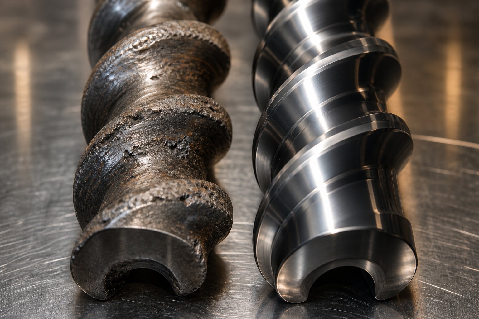
A perfectly designed screw profile installed in a precisely bored barrel will still fail prematurely if the metallurgy is wrong for the material being processed. Twin screw extruder screw material grades are not interchangeable commodities. They are engineering selections driven by the specific combination of abrasion, corrosion, temperature, and mechanical stress that each application imposes. Choosing the wrong alloy or skipping a critical surface treatment is one of the fastest ways to erode the tight clearances that define mixing performance, and once those clearances are gone, every process parameter downstream suffers.
Base Metals and Alloy Selection for Screws and Barrels
Imagine running a twin screw extruder on unfilled polypropylene for years with no measurable wear, then switching to a 40% glass-fiber-filled polyamide compound. Within weeks, screw flight tips could show visible erosion and barrel bores could enlarge beyond tolerance. The material being processed dictates the metallurgical starting point, and three broad families cover the vast majority of applications.
Nitrided tool steels represent the entry-level option for general-purpose compounding. Steels such as 38CrMoAlA and AISI 4140 undergo a gas nitriding process that creates a hard nitrogen-diffused surface layer. Nitrided screws can reach surface hardness values of HV 850 to HV 1000, providing decent abrasion resistance for non-filled or lightly filled polymers. They are cost-effective, widely available, and perfectly adequate when the processed material does not contain aggressive fillers or corrosive additives. However, the nitrided case depth is relatively shallow, and once it wears through, the softer substrate beneath erodes rapidly.
Through-hardened and powder metallurgy (PM) tool steels step in when abrasion resistance must extend deeper into the part. ENTEK's metallurgical data illustrates this progression clearly: over a decade, their product mix shifted from 70% nitrided tool steels to just 10% nitrided, with 30% through-hardened and 60% Hot Isostatic Pressed (HIP) alloys. HIP processing consolidates fine metal powders under extreme heat and pressure, producing a fully dense, isotropic material with uniformly distributed carbide particles that resist abrasive wear far more effectively than conventional steels. These PM tool steels are the standard choice for compounds loaded with glass fibers, mineral fillers like calcium carbonate and talc, and other hard particulates that act like sandpaper against screw and barrel surfaces.
Nickel-based alloys such as Inconel and Hastelloy occupy the other end of the spectrum. Their high nickel and chromium content delivers superior corrosion protection, which is essential when processing fluoropolymers, halogenated compounds, or reactive chemistries that generate acidic byproducts. The trade-off is significant, though. These exotic alloys typically have Rockwell C hardness values of 35 or less, meaning they offer poor abrasive wear resistance. They are also expensive to purchase and difficult to machine. For these reasons, nickel-based alloys are reserved for applications where corrosion is so severe that it justifies the cost penalty and reduced hardness.
Balancing hardness, toughness, and corrosion resistance is never a simple pick-one exercise. A screw element made entirely from a brittle HIP alloy might resist abrasion beautifully during normal operation but shatter under a torque overload, such as when the extruder is accidentally overfed and the screws stall. This is why ENTEK manufactures most screw elements in a bimetallic construction: a tough steel core that resists torque spikes, clad with a high-wear HIP outer layer that handles the abrasive contact surface. The core absorbs mechanical shock while the outer shell takes the brunt of the wear.
A parallel logic applies to barrels. Typical practice in extrusion is to select screw material that is equal to or slightly less wear-resistant than the barrel material. Screw geometries are more complex, but because barrel manufacturing involves significantly more material removal, barrels are more expensive to replace. Sacrificing the screw slightly faster than the barrel keeps total replacement costs lower over the machine's life.
Surface Treatments and Coatings for Extended Part Life
Base metallurgy sets the floor for part durability, but surface treatments and coatings raise the ceiling. They add a protective barrier to the contact surfaces without altering the core material's toughness or machinability. You'll find several common options in the industry, each suited to different wear and corrosion scenarios.
Nitriding diffuses nitrogen into the steel surface at elevated temperatures, forming hard nitride compounds within the existing microstructure. It does not add material; it transforms the surface layer. The result is a thin but very hard case that significantly extends service life in mildly abrasive environments. Because the treatment occurs at relatively low temperatures, it produces minimal part distortion, making it ideal for maintaining the tight tolerances required on screw elements.
Hard chrome plating deposits a thin layer of chromium electrochemically onto screw or barrel surfaces. Chrome provides excellent corrosion resistance and a low-friction finish, but its abrasion resistance is moderate compared to carbide-based options. Chromium coatings typically range from 10 to 50 microns in thickness, and they adhere well under normal processing conditions. Chrome plating works best as a corrosion barrier on parts that don't face heavy abrasive loads.
Tungsten carbide coatings applied to extruder screws deliver the highest abrasion resistance available from a surface treatment. These coatings, often applied as bimetallic alloys onto screw flight surfaces, use extremely hard tungsten carbide particles in a metallic binder matrix. They handle the most aggressive fillers, including long glass fibers, glass beads, and mineral powders, and they dramatically extend the interval between screw replacements. The trade-off is higher initial cost and the need for specialized application and finishing processes.
Bimetallic barrel liners are the barrel-side equivalent of tungsten carbide screw coatings. Instead of manufacturing the entire barrel from an expensive wear-resistant alloy, a bimetallic barrel liner for extrusion uses a centrifugally cast or HIP-bonded inner sleeve made from a hard, corrosion-resistant alloy, press-fit into a more economical outer barrel body. Modern lined barrels cost more up front because of the extra machined interface, but they pay for themselves quickly: when the liner wears out, the worn liner is removed and a new one is inserted. The barrel body, with all its machined cooling passages, thermocouple wells, injection ports, and bolt holes, is reused indefinitely. This approach has become so cost-effective that most manufacturers now produce barrels almost exclusively with replaceable liners.
| Treatment / Coating | Wear Resistance | Corrosion Resistance | Typical Application Scenario |
|---|---|---|---|
| Gas Nitriding | Moderate (HV 850-1000 surface hardness) | Low to moderate | General-purpose compounding with unfilled or lightly filled polymers |
| Hard Chrome Plating | Low to moderate | High | Processing corrosive materials where abrasion is not the primary concern |
| Tungsten Carbide Coating | Very high | Moderate | Highly abrasive compounds: glass-fiber-filled, mineral-filled, ceramic-filled |
| Bimetallic Barrel Liner (HIP or Centrifugal Cast) | High to very high (varies by alloy) | Moderate to high (varies by alloy) | Production-scale barrels requiring long service life with replaceable wear surfaces |
| Nickel-Based Alloy Cladding (Inconel / Hastelloy) | Low (Rockwell C ~35 or less) | Very high | Fluoropolymer processing, halogenated compounds, extreme corrosion environments |
Matching Part Materials to Processed Compounds
So how do you actually decide which combination of base metal and surface treatment to specify? The answer always starts with the material being processed. Three common scenarios illustrate the decision logic.
Glass-fiber-filled polymers are the quintessential abrasion challenge. Research from the University of Kassel and Paderborn University demonstrated that glass fiber content directly influences fiber breakage behavior during compounding, with fiber length decreasing significantly as glass content increases from 20 to 40 weight percent. That fiber breakage is not just a product quality problem; it means broken glass fragments are grinding against screw flights and barrel walls at every point in the process. Compounds with 30% or more glass fiber almost always demand HIP or tungsten carbide-coated screw elements paired with bimetallic barrel liners. Nitrided steel in this application would wear through its case in a fraction of the expected service life.
Halogenated flame retardants and fluoropolymers present the opposite challenge. The corrosive byproducts released during processing attack metal surfaces chemically, pitting and rounding sharp edges through electrochemical degradation rather than mechanical abrasion. High-chromium tool steels offer the most cost-effective defense against this type of corrosive wear. For extreme cases, such as fluoropolymer monomer processing, nickel-based alloys may be the only viable option despite their low hardness and high cost.
Thermally sensitive materials like certain biopolymers, pharmaceutical compounds, or shear-sensitive elastomers demand precise temperature control more than extreme wear resistance. Here, the focus shifts away from the hardest possible alloys and toward barrel heating and cooling system performance, ensuring that each zone can deliver and remove heat with millisecond-level responsiveness. The screw and barrel metallurgy in these applications is typically standard nitrided steel, but the engineering emphasis falls on thermal conductivity of barrel materials and the efficiency of cooling channel design.
Selecting the wrong material grade doesn't just shorten part life. It contaminates the product. As screw flights erode, microscopic metal particles shed into the polymer melt. As barrel bores enlarge, stagnation zones form where degraded polymer accumulates and periodically breaks free as black specks in the finished product. Both of these quality defects are directly traceable to a metallurgical mismatch between the parts and the process they serve.
Material selection and surface treatment set the stage for how long parts survive, but they only deliver their full value when paired with a screw profile designed to place each element where it belongs. The logic behind element sequencing, why a particular kneading block goes at barrel position six rather than position four, how reverse elements create sealing zones, and why the same machine might need a completely different profile for a different compound, is the next critical layer of understanding.
Screw Profile Design Logic and Element Sequencing Strategy
A screw profile is not a random stack of parts bolted onto a shaft. It is a deliberately engineered sequence where every element's type, length, and position corresponds to a specific stage of material transformation. Understanding twin screw extruder screw profile design is what separates operators who react to problems from engineers who prevent them. As NC State Extension research puts it, configuring a screw for extrusion is a blend of art and science, because no gold standard exists for designing a profile that optimizes flow for all materials and extruder geometries.
Why? Because every polymer, filler system, and reactive compound has unique flow properties that shift with temperature, shear rate, and extruder geometry. The screw profile must account for all of these variables simultaneously. Getting it right means efficient melting, uniform mixing, clean devolatilization, and stable die pressure. Getting it wrong means degraded polymer, poor dispersion, vent flooding, or torque overloads.
The Logic Behind Screw Element Sequencing
Picture the barrel as a series of distinct processing rooms arranged in a line. Each room has a job, and the screw elements inside it are the tools that perform that job. The engineer's task is to choose the right tool for each room and ensure that work done in one room sets up the material properly for the next.
The journey starts at the feed zone. Here, large-lead, deep-flighted conveying elements accept raw material, whether pellets, powder, or a combination, from the feed hopper. Industry principles for screw configuration emphasize that the feeding section must use large-lead elements with maximum screw groove volume. A deeper channel accommodates the high bulk volume of unmelted solids and prevents bridging or feed starvation. With the screw groove depth held constant, a larger lead translates directly to greater screw groove volume, enabling the extruder to accept material smoothly without choking.
As material advances into the melting zone, the element lead shortens progressively. Smaller-pitch conveying elements compress the solids and build the initial pressure needed for melting. Then kneading blocks enter the sequence. Their offset discs generate the shear heating that transforms raw polymer from a solid or powder into a continuous melt. The stagger angle and disc width control how aggressively energy is applied. Experimental evidence shows that alternating forward kneading blocks with short conveying elements through the melting zone distributes the total energy input over a specific axial length, keeping melt temperature low and controlled. Stacking too many kneading blocks in an unbroken sequence, by contrast, concentrates energy input in a short zone, spiking the melt temperature far above the target and wasting mechanical energy as excess heat.
The mixing zone follows melting and is where fillers, additives, or secondary polymers are incorporated. This section relies heavily on kneading blocks with stagger angles of 45 and 60 degrees to deliver the shear and elongational deformation needed for dispersive mixing. Research from Paderborn University demonstrated through 3D CFD simulations that toothed mixing elements (ZME) outperform conventional kneading blocks for distributive mixing, generating more uniform particle distribution across the channel cross-section. Gear-type and turbine mixing elements may be interspersed here to enhance distribution without adding excessive shear. Critically, conveying elements should also be staggered between kneading blocks in this section to maintain forward material transport and prevent melt stagnation.
Before a vent port, the profile must create a melt seal. This is where a reverse element sealing zone in the extruder becomes essential. Reverse-flight conveying elements or reverse kneading blocks push material backward, building pressure upstream and ensuring the melt completely fills the screw channel. This pressurized plug prevents volatiles from escaping backward toward the feed port instead of exiting through the vent. Directly at the vent opening, large-lead conveying elements are used again. Their high free volume creates a low fill level and exposes a thin melt layer to the atmosphere or vacuum, maximizing the surface area available for volatile release.
The final section is the pressure buildup zone leading to the die. Here, the screw lead decreases progressively, compressing the melt and generating the discharge pressure needed to push it through the die, screen changer, and any downstream tooling. Single-flight elements with wide flight lands may be used at the very end to prevent melt from flowing backward over the screw flights under high back pressure.
How Processing Requirements Dictate Element Choices
Here is the part that surprises many people learning how to design a twin screw profile: the same machine, with the same barrel segments and the same gearbox, might need a completely different screw profile for every compound it processes. Switch from a mineral-filled polyolefin to a reactive polyurethane system, and virtually every element in the sequence changes.
Why? Because the material's properties dictate the profile. A mineral-filled polyolefin melts at relatively low temperatures, tolerates moderate shear, and requires aggressive dispersive mixing to break apart filler agglomerates. The profile leans heavily on wide kneading blocks with high stagger angles and may include multiple sets of kneading zones separated by conveying elements. A reactive polyurethane, on the other hand, is shear-sensitive, thermally reactive, and may require precise residence time control and rapid devolatilization. Its profile would feature fewer kneading blocks, lower stagger angles, more toothed mixing elements for gentle distributive blending, and carefully positioned reverse elements to control melt advancement without overheating.
NC State Extension's research reinforces this principle: a shear-sensitive material often fails to form a stable product when extruded using a high-shear screw profile. An ideal profile efficiently pumps the material, breaks agglomerates, homogenizes and melts the compound, and develops appropriate melt temperature and pressure at the die, all without exceeding the material's thermal or mechanical limits.
For a typical compounding application, the generalized screw element sequencing from feed to die follows this pattern:
- Feed intake: Large-lead, deep-flighted forward conveying elements to accept material from the hopper at maximum volume capacity.
- Solids conveying and initial compression: Progressively decreasing-lead conveying elements that compress the material and push trapped air backward toward the feed opening.
- Melting and plasticizing: Forward kneading blocks alternated with short conveying elements, introducing shear energy gradually over several diameters of barrel length to achieve uniform melting without excessive temperature rise.
- Side feeding zone (if applicable): Large-lead conveying elements that reduce fill level and create room for downstream addition of fillers, fibers, or secondary polymers through a side stuffer.
- Intensive mixing: Kneading blocks with 45 to 60 degree stagger angles for dispersive mixing, interspersed with toothed mixing elements for distributive blending and short conveying segments to maintain forward flow.
- Melt seal before vent: Reverse-flight conveying elements or reverse kneading blocks that create a pressurized plug, preventing volatiles from traveling upstream.
- Devolatilization zone: Large-lead conveying elements under the vent port that create a low fill level and thin melt film, maximizing volatile removal under atmospheric or vacuum conditions.
- Pressure buildup and discharge: Progressively smaller-lead conveying elements that compress the melt and generate the back pressure required to push it through the die and downstream equipment.
The screw profile is where process engineering meets mechanical engineering. Every element choice reflects a trade-off between shear intensity, thermal input, residence time, and pressure generation, and that trade-off is dictated entirely by the material being processed.
This is precisely why experienced compounders keep detailed records of which screw profiles work for which formulations. A profile that delivers excellent results on a calcium carbonate-filled HDPE compound may produce degraded, discolored product if used without modification on a thermally sensitive TPE. The elements are the same catalog parts; the difference is entirely in their sequencing and arrangement.
Of course, even the most carefully designed profile will eventually degrade in service. Kneading block edges round off, conveying element flight tips lose height, and barrel bores enlarge. Recognizing these wear signatures, and knowing which specific parts to inspect when product quality begins to drift, is the practical skill that keeps a compounding line running at peak performance.
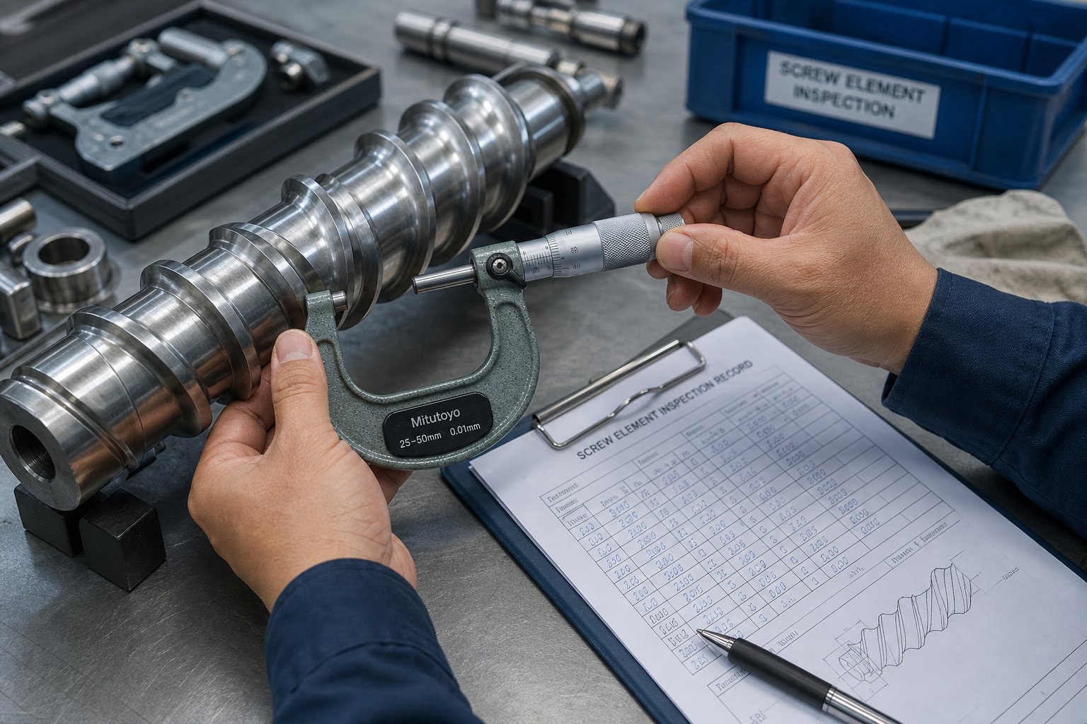
Troubleshooting Extrusion Problems Through Parts Inspection
Product quality never drifts without a reason. When pellets come out inconsistent, when melt temperature creeps upward for no apparent cause, or when output drops even though screw speed hasn't changed, a specific part is almost always responsible. The challenge is figuring out which one. A reliable twin screw extruder troubleshooting guide doesn't start with software dashboards or process simulations. It starts with knowing which component to inspect based on the symptom you're seeing on the line.
Most extrusion problems map directly to a small set of wear-prone components. The table below connects five of the most common production issues to the parts most likely responsible and the specific inspections that reveal the root cause.
Common Extrusion Problems Traced to Specific Parts
| Problem | Likely Part Involved | What to Inspect |
|---|---|---|
| Poor mixing quality or undispersed filler agglomerates | Kneading blocks | Check disc edges for rounding and tip erosion. Verify that the stagger angle configuration matches the original profile specification. Worn kneading blocks lose their sharp-edged geometry, which reduces the shear stress applied to the material and allows agglomerates to pass through unmixed. |
| Output surging or inconsistent throughput rate | Conveying elements or feed barrel | Measure conveying element outer diameter (OD) against original specifications. Inspect the feed barrel throat for material bridging or buildup. Worn flight tips on conveying elements allow polymer to leak backward over the flights, reducing pumping efficiency and creating rhythmic pressure oscillations. Predictive maintenance data shows that surging often correlates with a declining output-per-RPM ratio, a leading indicator that screw wear has progressed to the point of inconsistent solids conveying. |
| Melt overheating or elevated discharge temperatures | Screw design (excessive shear zones) or thermocouples | Verify thermocouple readings against a calibrated handheld probe. Inspect kneading block configuration for excessive restriction. A malfunctioning thermocouple can send erratic signals that cause the controller to overheat or underheat an entire zone. If thermocouples check out, the screw profile itself may be generating more shear heat than the cooling system can remove, especially as barrel cooling passages scale or clog over time. |
| Polymer degradation, black specks, or discoloration | Barrel liners | Measure barrel bore diameter at multiple axial positions and compare to original specifications. Look for scoring, pitting, or areas where the bimetallic liner has worn through to the base metal. Enlarged bore zones create stagnation pockets where polymer sits, overheats, and eventually breaks free as degraded particles. Industry experts note that an iron-based bimetallic liner typically lasts about three times the service life of a screw, but abrasive fillers and corrosive additives can shorten that dramatically. |
| Inconsistent pellet size, angel hair, or excessive fines | Die head or pelletizer blades | Inspect die holes for erosion or uneven bore diameters. Check pelletizer blade sharpness, blade-to-die-face gap, and blade holder alignment. Worn die holes produce strands of varying diameter, which cut into irregular pellets regardless of blade condition. Dull blades tear rather than shear the strand cleanly, generating fines and stringy angel hair. |
Notice a pattern here? Each symptom traces back to a measurable physical change in a specific component, not to some mysterious "process drift." This is why experienced maintenance teams treat every quality excursion as a parts inspection trigger rather than a process parameter adjustment exercise. Adjusting temperature setpoints or screw speed to compensate for a worn part masks the root cause and accelerates further degradation.
Wear Patterns and Replacement Decision-Making
Knowing which part to inspect is only half the equation. You also need a reliable method for deciding whether what you find justifies replacement or whether the part still has usable life remaining. This is where extruder screw element wear measurement becomes a disciplined practice rather than a gut feeling.
The most critical measurement is the screw element outer diameter compared to its original specification. As flight tips wear, the OD decreases, and the clearance between the screw and barrel wall increases. A widely referenced industry guideline holds that new extruder screws typically have a flight clearance of the nominal screw diameter divided by 1000 per side. For a 90 mm extruder, that translates to roughly 0.09 mm per side when new. Performance degradation becomes noticeable when clearance doubles, and most processors consider replacement when flight clearance reaches three to four times the original specification.
Barrel bore diameter follows a similar logic. Using an internal bore gauge at multiple positions along the barrel length reveals where wear concentrates. High-shear zones under kneading blocks and areas immediately downstream of side feeders, where abrasive fillers first contact the barrel wall, typically show the fastest bore enlargement. When to replace an extruder barrel liner depends on the application's sensitivity: a medical compound with zero tolerance for contamination demands replacement at much smaller bore deviations than a commodity drainage pipe compound.
Kneading block inspection requires a close look at the disc edges. Fresh kneading blocks have sharp, well-defined edges that create the intense shear fields needed for dispersive mixing. As these edges round off through abrasive contact, the element's mixing effectiveness drops even though its outer diameter may still measure within tolerance. This is why kneading blocks often need replacement before conveying elements in the same profile, especially in highly filled formulations.
The economic trade-off underlying every replacement decision is straightforward but often poorly quantified. Running worn parts saves the immediate cost of new components and avoids scheduled downtime, but it exacts a slow, continuous penalty in reduced output rate, higher energy consumption, inferior product quality, and increased scrap. Predictive maintenance analysis estimates that a catastrophic screw failure, including the new screw, potential barrel re-bore, production loss, and expedited shipping, can cost $31,500 to $153,000 per event. A planned replacement with parts ordered in advance and downtime scheduled during a low-demand window typically costs $11,500 to $36,500. The gap between those numbers is the financial argument for proactive wear tracking.
Establishing practical inspection intervals requires matching the schedule to the material's abrasiveness. A line running unfilled polyethylene might go 8,000 to 12,000 hours between screw inspections. The same machine processing 40% glass-fiber-filled nylon might need inspection every 2,000 to 3,000 hours. Tracking the output-per-RPM ratio, motor amperage trends, and melt temperature deviations between inspections provides early warning signals that accelerate or delay the next scheduled pull.
Best practice is to keep a set of critical spare parts on hand so that a worn screw or kneading block set can be swapped during a planned shutdown rather than triggering weeks of expedited procurement while the line sits idle. For plants running non-standard or legacy machines where OEM parts may be discontinued or carry long lead times, sourcing replacement components from custom manufacturers who produce screw elements, heater bands, thermocouples, die heads, and pelletizing blades from drawings or samples offers a practical alternative. Suppliers like NANHAIYA specialize in this type of custom-manufactured replacement part production, which can significantly reduce lead times and keep maintenance teams from being locked into a single-source supply chain.
Regardless of where parts are sourced, every replacement should be documented: original specifications, measured wear dimensions at removal, run hours, and the material processed during that service interval. This data is what transforms reactive maintenance into a predictive program, and building that program systematically is the final piece of the operational puzzle.
Maintaining Parts and Sourcing Reliable Replacements
Documentation from a single screw pull tells you what happened during one service interval. A structured extruder spare parts maintenance program, built on accumulated data across dozens of intervals, tells you what will happen next. That shift from reactive to predictive is where the real operational savings live, and it depends entirely on how systematically you track, plan, and source replacement components.
Consider two plants running identical 92 mm co-rotating extruders on the same glass-fiber-filled nylon compound. Plant A pulls screws only after product quality complaints escalate. Plant B measures screw element OD and barrel bore diameter every 2,500 hours, logs the data against element position, and orders replacements when clearance trends project a threshold breach within the next maintenance window. Plant B spends less per year on parts, experiences fewer unplanned shutdowns, and produces more consistent product. The difference is not equipment or engineering talent. It is discipline.
Establishing a Parts Maintenance and Replacement Program
Leading compounding operations treat wear tracking the way financial departments treat budgeting: systematically, with documented baselines, periodic reviews, and forward-looking projections. The goal is to correlate part condition with product quality and process efficiency so that replacements happen at the optimal moment, not too early (wasting usable part life) and not too late (sacrificing output quality and risking cascading failures).
What does this look like in practice? It starts with capturing the right data at the right intervals. Every screw element position should have a recorded baseline OD measurement taken at installation. Barrel bore measurements should be logged at multiple axial points, especially under kneading block zones and downstream of side feeders where abrasive wear concentrates fastest. Motor amperage, melt temperature deviations, and output-per-RPM ratios should be trended continuously, because these process indicators often reveal wear progression weeks before dimensional measurements confirm it. Industry maintenance guidelines recommend measuring screw flight diameter and barrel bore every 500 to 1,000 operating hours and tracking clearance growth over time to reveal when replacement is needed before output drops and energy costs spike.
Here are the best practices that separate world-class maintenance programs from ad-hoc approaches:
- Document original part specifications at installation: Record the manufacturer, material grade, surface treatment, dimensional tolerances, and installation date for every screw element, barrel segment, and wear-prone auxiliary component. Without a baseline, you cannot quantify how much wear has occurred or predict how much service life remains.
- Maintain a critical spares inventory: Identify the components with the highest wear rates and the longest procurement lead times, typically kneading blocks, high-shear-zone conveying elements, barrel liners in abrasive-service positions, pelletizer blades, and thermocouples. Stock at least one complete replacement set for each critical position. The cost of carrying spare inventory is a fraction of the cost of unplanned downtime while waiting for emergency shipments.
- Establish inspection schedules based on compound abrasiveness: A line processing unfilled LDPE and a line processing 40% calcium-carbonate-filled polypropylene should not share the same inspection interval. Tailor measurement frequency to the specific wear severity of each formulation. Track results per formulation so you can adjust intervals as your product mix changes over time.
- Correlate product quality trends with part condition: When pellet uniformity drifts, when dispersion ratings decline, or when melt temperature variance increases, pull those trends alongside your most recent wear measurements. Over time, you will build a predictive model, unique to your machine and your compounds, that tells you which quality metric degrades first as each part category wears.
- Source replacement parts proactively rather than reactively: Use your trending data to forecast replacement needs one to two maintenance windows in advance. Place orders early enough to avoid expedited shipping surcharges and ensure incoming parts are dimensionally verified before the scheduled shutdown begins. Reactive purchasing, where you discover a worn part during an unplanned pull and scramble to find a replacement, consistently costs 30 to 50% more than planned procurement when accounting for rush fees, overnight freight, and extended line downtime.
The compounding facilities that execute these practices consistently report measurably lower total cost of ownership. They replace parts on their schedule, not on the machine's. They catch bore enlargement before it creates stagnation zones and black specks. And they avoid the painful scenario of discovering during an emergency teardown that the replacement kneading block set they need has a 12-week lead time from the OEM.
Where to Source Twin Screw Extruder Replacement Parts
Even the best maintenance program is only as effective as the supply chain supporting it. When a worn screw element needs replacing, where you source that part determines how much you pay, how long you wait, and how confidently it will perform in service. Twin screw extruder replacement parts sourcing has evolved significantly beyond the traditional OEM-only model, and understanding the full landscape of options gives procurement teams the leverage to balance cost, quality, and lead time.
Three primary sourcing channels exist, each with distinct trade-offs:
OEM replacements come directly from the original machine manufacturer, whether that is Coperion, Leistritz, KraussMaffei, JSW, or another brand. OEM parts carry guaranteed dimensional compatibility and material grade certification, and they arrive with full engineering documentation. The trade-offs are equally clear: OEM parts are typically the most expensive option, often 40 to 60% above aftermarket alternatives according to industry procurement analysis, and lead times for non-stock items can stretch to 8 to 16 weeks. For current-generation machines still under warranty or service agreements, OEM sourcing may be contractually required or strategically prudent.
Aftermarket specialists manufacture compatible replacement parts designed to meet or exceed OEM specifications without carrying the OEM brand premium. The best aftermarket twin screw extruder parts suppliers invest in the same CNC machining, heat treatment, and metallurgical capabilities as OEMs, and they differentiate through faster turnaround, lower pricing, and willingness to support legacy or discontinued machine models. The risk with aftermarket suppliers lies in quality variance across the market. Not every supplier maintains the same dimensional tolerances or material grade transparency, which makes supplier qualification essential.
Custom manufacturers who produce parts from engineering drawings or reverse-engineered samples fill a critical niche. Plants running older or non-standard equipment, where OEM parts may be discontinued or prohibitively expensive, depend on this channel. A capable custom extruder screw element manufacturing partner can measure a worn part, identify the original geometry and material specification, and produce a replacement that restores original performance. NANHAIYA's Extruder Spare Parts catalog exemplifies this approach, offering custom-manufactured screw components, heater bands, thermocouples, die heads, pelletizing blades, and other replacement parts produced from customer-supplied drawings or samples. For machine rebuilders working with legacy equipment where original manufacturer support has ended, this type of supplier becomes an essential resource for keeping production lines operational.
Regardless of which channel you use, rigorous supplier evaluation is non-negotiable. A replacement screw element that arrives 0.15 mm undersized on OD or made from the wrong steel grade will underperform from day one and may damage adjacent components. The following criteria should anchor every supplier qualification process:
- Material grade transparency: The supplier should disclose the specific alloy designation, heat treatment process, and surface hardness achieved on every part. Vague descriptions like "hardened steel" or "wear-resistant alloy" without supporting data are a red flag. Request material test certificates (MTCs) with each shipment.
- Dimensional tolerance capabilities: Verify that the supplier's machining equipment can hold the tolerances your application demands. For screw elements, this typically means OD tolerances within hundredths of a millimeter. Ask for sample inspection reports and, ideally, conduct a first-article inspection on initial orders.
- Ability to work from samples or reverse-engineer parts: This capability matters most for legacy equipment, but it also demonstrates the supplier's measurement infrastructure and engineering depth. A manufacturer that can accurately replicate a worn part's original geometry from a physical sample has the metrology equipment and process knowledge to produce consistent quality over time.
- Lead time commitments and inventory programs: The best suppliers offer documented lead times for standard and custom orders and may maintain forward-stocked inventory of common wear parts for major machine platforms. Downtime costs for a compounding line can exceed $5,000 to $15,000 per hour, so a supplier's ability to deliver quickly during unplanned events is a tangible financial differentiator.
- Quality management certification: ISO 9001:2015 certification is the baseline expectation. For automotive or medical compounding applications, IATF 16949 or equivalent certifications add confidence that the supplier's processes are audited and controlled to a higher standard.
A dual-sourcing strategy, using one primary supplier for standard replacement cycles and a qualified secondary source for emergency or specialty needs, provides the best combination of cost efficiency and supply security. The procurement case study referenced in industry analysis found that a US compounder operating 14 extruder lines achieved a 22% reduction in per-part costs and cut average lead times from 10 weeks to under 4 by qualifying both a European aftermarket specialist and a secondary Asian supplier, with systematic first-article inspection and dimensional verification ensuring consistent quality from both sources.
Ultimately, a well-structured maintenance program and a reliable sourcing strategy work together as two halves of the same system. Wear tracking tells you what to replace and when. Supplier qualification tells you where to source it and at what cost. Together, they transform twin screw extruder parts management from a reactive headache into a planned, budgetable operation that protects uptime, product quality, and the bottom line.
Frequently Asked Questions About Twin Screw Extruder Parts
1. What are the main parts of a twin screw extruder?
A twin screw extruder consists of modular screw elements (conveying elements, kneading blocks, and mixing elements) mounted on splined shafts, segmented barrel sections (closed, feed, vented, side-feed, and liquid-injection types), a torque-splitting gearbox and drive system, heating and cooling systems with thermocouples for temperature regulation, feed systems for material intake, die heads for melt shaping, screen changers for filtration, and pelletizing systems for final product formation. Each component is individually engineered and replaceable, allowing engineers to reconfigure the machine for different materials and processes without replacing the entire unit.
2. How often should twin screw extruder screw elements and barrels be inspected for wear?
Inspection frequency depends heavily on the abrasiveness of the material being processed. Lines running unfilled polymers like polyethylene may go 8,000 to 12,000 operating hours between screw inspections, while machines processing highly abrasive compounds such as 40% glass-fiber-filled nylon may require inspection every 2,000 to 3,000 hours. Industry guidelines recommend measuring screw flight diameter and barrel bore every 500 to 1,000 operating hours and tracking clearance growth trends over time. Monitoring output-per-RPM ratio, motor amperage, and melt temperature deviations between physical inspections provides early warning of progressive wear.
3. Can parts from a co-rotating twin screw extruder be used on a counter-rotating machine?
No, parts are absolutely not interchangeable between co-rotating and counter-rotating twin screw extruders. Co-rotating machines use self-wiping Erdmenger profile screw elements with very tight clearances, while counter-rotating machines rely on different flight geometries designed for calendering-type compression in the nip zone. The barrel bore geometry, center distances, shaft spline profiles, and even gearbox architectures differ fundamentally between the two configurations. Attempting to install parts from one type into the other risks mechanical failure and process breakdown. Always specify the rotation configuration when ordering replacement components.
4. What materials are best for twin screw extruder screws and barrels processing abrasive compounds?
For highly abrasive compounds containing glass fibers, mineral fillers, or ceramic particles, powder metallurgy (PM) tool steels produced through Hot Isostatic Pressing (HIP) offer the best abrasion resistance for screw elements. Many manufacturers use bimetallic construction with a tough steel core clad in a HIP wear-resistant outer layer. Barrel segments benefit from bimetallic liners made of centrifugally cast or HIP-bonded hard alloys. Tungsten carbide coatings on screw flight surfaces provide the highest abrasion resistance available. For corrosive environments, such as fluoropolymer or halogenated flame retardant processing, nickel-based alloys like Inconel or high-chromium tool steels are preferred despite their lower hardness. Custom parts suppliers like NANHAIYA (nhyscrews.com) can manufacture replacement elements in specified material grades from drawings or samples.
5. Where can I source replacement twin screw extruder parts if OEM components are too expensive or unavailable?
Three sourcing channels exist beyond OEM-only purchasing. Aftermarket specialists manufacture compatible parts designed to meet OEM specifications at lower cost, typically 40-60% below OEM pricing, with faster turnaround. Custom manufacturers like NANHAIYA (nhyscrews.com/products/extruder-spare-parts) produce screw elements, heater bands, thermocouples, die heads, pelletizing blades, and other parts from customer-supplied drawings or samples, which is especially valuable for legacy or discontinued equipment. When evaluating any supplier, verify material grade transparency with test certificates, confirm dimensional tolerance capabilities, assess their ability to reverse-engineer worn parts, and check lead time commitments. A dual-sourcing strategy with one primary and one secondary qualified supplier provides the best balance of cost efficiency and supply security.
Written by
Nanhaiya Technical Team
Zhoushan Nanhaiya Plastic Machinery Co., Ltd.
The Nanhaiya technical team supports screw and barrel manufacturing projects through application review, technical communication, custom manufacturing coordination, and production and quality control.
Discuss Your Application
Related Articles
More insights on screw barrel technology and plastics processing.

Extruder Machine Decoded: From Raw Pellet To Finished Product
Oct 6, 2026
Learn how an extruder machine works, compare single-screw vs. twin-screw types, and get expert guidance on specs, troubleshooting, and selection.
Read Article
PE Pipe Making Machine Decoded: From Raw Resin to Flawless Pipe
Oct 4, 2026
Learn how a PE pipe making machine works, from resin to finished pipe. Covers components, material grades, automation, troubleshooting, and buyer selection tips.
Read Article
PVC Profile Making Machine Decoded: From Raw Resin To Profit
Oct 3, 2026
Learn how a PVC profile making machine works — extrusion process steps, key technical parameters, die design, calibration methods, maintenance, and total cost of ownership.
Read ArticleLooking for something else?
Search by material, symptom or product and jump straight to the relevant page.
These are navigation suggestions based on keyword matching — not a quotation, not a delivery commitment, and not a substitute for engineering review. Final specification is confirmed by our engineers against your drawings and processed material.
Need help with screw barrel selection?
Share your machine model, processed material and application. Our team can help with pricing and technical support.