

What a Twin Screw Extruder Machine Actually Does
Imagine you need to blend, melt, and shape a complex mix of polymers, fillers, and additives into a perfectly uniform product — all in one continuous operation. That is exactly the job a twin screw extruder machine is built to handle. Yet most buyers step into the purchasing process without fully understanding how these machines differ from simpler alternatives or why the distinction matters so much to their bottom line.
Defining the Twin Screw Extruder Machine
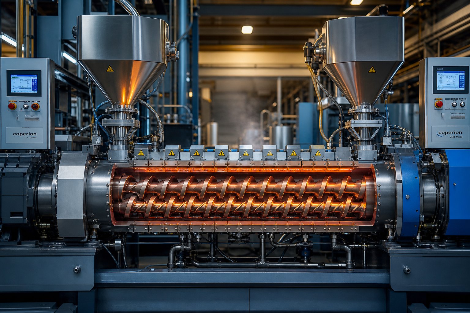
A twin screw extruder is a processing machine that uses two co-rotating or counter-rotating intermeshing screws, housed inside a closely fitted heated barrel, to convey, melt, mix, and pressurize polymers and other materials into a continuous, homogeneous output.
That definition captures the core of what this equipment does, but the real story lies in how it does it. Unlike a single screw extruder — which relies primarily on friction and viscous drag to push material forward — a twin screw extruder achieves positive displacement conveying. The intermeshing flight geometry means a specific volume of material advances with each screw rotation, regardless of the material's viscosity or flow characteristics.
This distinction creates two critical advantages. First, the twin screw design is inherently self-wiping: the flights of one screw continuously sweep the surface of the other, preventing material from stagnating, degrading, or building up inside the barrel. Second, it delivers far superior distributive and dispersive mixing. A single screw extruder struggles to fully turn over channel contents because material tends to stay in the same radial position due to shear-thinning effects. A twin-screw extruder machine, by contrast, transfers the entire channel of material from one screw to the other multiple times, achieving thorough, full-channel mixing with a narrow residence time distribution.
Why Twin Screw Extrusion Dominates Advanced Processing
When you hear the term "extruders" in a manufacturing context, the meaning can range from simple melt-pumping devices to sophisticated continuous reactors. Understanding extruders meaning in the context of twin screw technology is essential because these machines have moved well beyond basic plastics processing. They serve as the backbone of polymer compounding, and they are equally established in food processing, chemical manufacturing, and — increasingly — the pharmaceutical industry, where they continuously mix APIs with polymeric excipients for advanced drug delivery systems like amorphous solid dispersions and implantable devices.
This cross-industry dominance is no coincidence. The twin screw extruder offers something no other continuous mixer matches: the ability to independently control conveying, melting, mixing intensity, and pressure generation along different zones of a single barrel. You'll find that flexibility is what separates it from every simpler alternative on the market.
This article is built as a process-engineering resource, not a product catalog. In the sections ahead, you'll learn not just what a twin screw extruder is, but how to evaluate configurations, interpret technical specifications, and optimize processing parameters — the details that truly determine whether your investment pays off or falls short.
How the Twin Screw Extrusion Process Works Step by Step
Knowing what a twin screw extruder is and understanding how to run one are two very different things. Most resources describe the hardware — screws, barrels, dies — and stop there. But the real value lies in understanding twin screw extrusion as a controllable process with tightly interacting variables. Get the balance right, and you produce a flawless, uniform melt at maximum throughput. Get it wrong, and you face degraded material, surging output, or wasted energy.
Material Journey Through the Barrel Zones
Picture raw polymer pellets dropping from a gravimetric feeder into the barrel opening. From that moment, the material passes through a series of distinct processing stages — each governed by a different combination of heat transfer, mechanical shear, and pressure.
- Feed zone (solid conveying): Loose pellets or powder land on the screws and are transported forward by the intermeshing flights. In a co-rotating twin screw extruder, this zone typically runs only partially filled. Air escapes rearward through the hopper, and the material compacts gradually as it advances. The barrel temperature here is usually set low — just enough to begin softening particle surfaces without premature melting that could block conveying.
- Transition zone (melting and plasticating): As the material moves downstream, barrel heaters raise the temperature while kneading elements introduce intense shear. The combination of conducted heat from the barrel wall and viscous dissipation from mechanical work transforms the solid granules into a continuous melt. Unlike flood-fed single screw systems that rely on a compact solid bed melting against the barrel, twin screw extrusion produces a dispersed melting pattern — individual pellets soften and merge within the melt pool, leading to faster and more uniform plasticating.
- Kneading zone (intensive mixing): This is where the real work happens. Kneading blocks with staggered disc angles apply high dispersive and distributive forces, breaking apart agglomerates, distributing additives, and homogenizing the melt. These zones are fully filled with material, and the flow resistance they create is what drives effective mixing.
- Metering zone (pressure building): In the final barrel sections, conveying elements compress the homogenized melt and build the pressure needed to push it through the die. Temperature control here is critical — too much heat degrades the polymer, while too little raises melt viscosity and drives up motor torque.
Each of these zones features independently controlled heating and cooling. A typical production-scale extruder system may have eight to twelve barrel segments, each with its own electric heater band and internal cooling channel. This segmented thermal architecture lets process engineers create precise temperature profiles — for example, a gentle ramp through the feed and transition zones followed by a slight reduction in the metering zone to prevent thermal degradation near the die.
How Screw Speed, Feed Rate, and Temperature Interact
Here is where most operators get tripped up: screw speed, feed rate, and barrel temperature are not independent dials you can turn in isolation. They form a tightly coupled triangle, and adjusting one always affects the other two.
Screw speed controls the shear rate applied to the material and influences the residence time distribution. Higher RPM increases mechanical energy input, which raises the melt temperature through viscous dissipation — even if barrel set points stay the same. Research into twin-screw compounding parameters confirms that screw speed and feed rate have the greatest impact on melt temperature, with higher speeds generating more shear energy in the mixing zones. At the same time, higher screw speed can shorten residence time if the feed rate is held constant, because the screw conveys material faster through partially filled zones.
Feed rate determines how full the screw channels are at any given point. Most co-rotating twin screw extruders operate in starve-fed mode, meaning a precision feeder meters material at a rate deliberately below the screw's maximum conveying capacity. This creates partially filled upstream zones where no pressure builds — a feature that gives engineers independent control over throughput and shear intensity. Increase the feed rate without adjusting screw speed, and you raise the fill level, which increases the residence time in kneading zones and can improve mixing. Push it too high, and you risk overfilling the screw extruder, causing excessive torque, vent flooding, or pressure surges at the die.
Barrel temperature profiles must respond to changes in the other two parameters. If you raise screw speed (adding more shear heat), you may need to increase cooling in the mixing zones to keep the melt within its processing window. If you lower the feed rate (reducing fill and extending residence time), barrel temperatures in the metering zone may need to drop to prevent thermal degradation.
The takeaway? Optimizing a twin screw extrusion process is never about finding the perfect RPM or the ideal temperature profile in isolation. It requires balancing all three variables simultaneously, guided by measurable outputs like melt temperature at the die, motor torque, and specific mechanical energy per kilogram processed. Engineers who treat the extruder system as an integrated process — rather than a collection of independent settings — consistently achieve better melt quality, higher throughput, and lower scrap rates.
Of course, these process variables only tell half the story. The physical configuration of the machine — whether the screws co-rotate or counter-rotate, run in parallel or conical geometry — fundamentally shapes which processing outcomes are even possible.
Types of Twin Screw Extruders and When to Choose Each
Most technical resources hand you a tidy list of twin screw extruder types and leave it at that. But knowing that co-rotating and counter-rotating configurations exist does not help you decide which one belongs on your production floor. The real question is: given your material, your throughput target, and your quality requirements, which configuration actually solves your processing problem? Let's break it down.
Co-Rotating vs Counter-Rotating Twin Screw Extruders
The distinction between a co rotating twin screw extruder and its counter-rotating counterpart comes down to one fundamental difference: the direction the two screws spin. That single variable reshapes nearly everything about how the machine handles material.
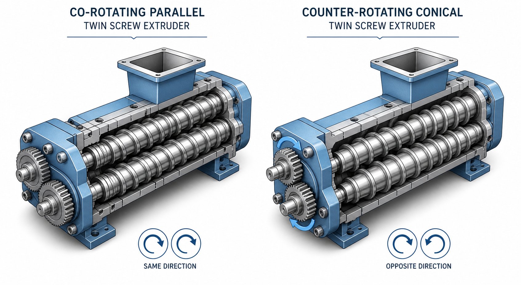
In a co-rotating design, both screws turn the same way. The fully intermeshing geometry forces material to transfer from one screw to the other at every engagement point, creating a complex deformation history with intense shear fields between the screws and between each screw and the barrel wall. This produces outstanding distributive and dispersive mixing — exactly what you need when breaking apart filler agglomerates, homogenizing polymer alloys, or promoting mass transfer in reactive extrusion. The self-wiping action is another major advantage: because one screw's flights continuously scrape the other's surface, dead zones are virtually eliminated, residence time distribution stays narrow, and product changeovers are faster.
Co-rotating machines also handle high screw speeds comfortably, which translates to higher throughput and greater specific energy input when the process demands it. That combination of mixing intensity, speed capability, and self-cleaning is why this configuration dominates compounding operations worldwide.
A counter-rotating twin screw extruder works on a different principle entirely. The screws spin in opposite directions, drawing material into the intermeshing region and advancing it through a calendering effect — repeated compressive and elongational deformation under comparatively gentle conditions. Shear stress stays lower than in the co-rotating type, and shear-induced heat generation is significantly reduced.
Why does that matter? Consider rigid PVC: it has a low thermal decomposition temperature and poor melt flow. Subject it to the intense shear of a co-rotating machine, and you risk degradation before you achieve proper fusion. The counter-rotating design lets you operate at high fill levels and low rotational speeds, keeping the extrusion temperature low enough for stable forming. That is precisely why counter-rotating extruders remain the standard workhorse for PVC pipe, sheet, and profile extrusion.
So when engineers evaluate a co rotating and counter rotating twin screw extruder side by side, the decision hinges on three factors: material sensitivity to shear and heat, the intensity of mixing required, and throughput expectations. High-performance compounding with fillers, nanocomposites, or reactive systems? Co-rotating wins. Shear-sensitive materials that need gentle, controlled processing at lower temperatures? Counter-rotating is the safer bet.
Parallel vs Conical Configurations
Within both co-rotating and counter-rotating categories, you'll encounter a second design split: parallel versus conical screw geometry.
A parallel twin screw extruder features two screws of uniform diameter along the entire barrel length. This is the standard configuration for high-throughput compounding, masterbatch production, and reactive extrusion. The consistent screw diameter means you can build long L/D ratios — 40:1, 48:1, or even higher — which gives you room for multiple mixing zones, side feeders, devolatilization vents, and liquid injection ports along the barrel. That processing flexibility is hard to replicate in any other geometry.
A conical twin screw extruder, by contrast, uses tapered screws with a larger diameter at the feed end and a smaller diameter at the discharge end. The taper provides two practical advantages. First, the large feed opening accepts bulky, low-density materials — like dry-blended PVC powder — more readily than a parallel barrel of equivalent output capacity. Second, the gradually decreasing screw channel volume creates a natural compression ratio without aggressive kneading elements, which suits materials that benefit from gentle, progressive pressure buildup.
Conical designs are almost exclusively counter-rotating and are most commonly found in PVC pipe and profile extrusion lines. They can generate higher discharge pressures relative to their size, but they sacrifice the modularity and extended processing length that parallel machines offer. You won't typically find conical extruders used for complex compounding tasks or multi-stage reactive processes — their shorter effective processing length simply doesn't provide enough real estate for those operations.
Choosing the Right Configuration for Your Application
Selecting the right twin screw extruder type is not about picking the "best" machine — it is about matching the machine's processing characteristics to your specific application demands. The table below compares the three most common configurations across the dimensions that matter most during the selection process.
| Dimension | Co-Rotating Parallel | Counter-Rotating Parallel | Conical (Counter-Rotating) |
|---|---|---|---|
| Typical Applications | Polymer compounding, masterbatch, reactive extrusion, nanocomposites, recycling | Specialty compounding, shear-sensitive blends, some PVC applications | PVC pipe, PVC profile, PVC sheet extrusion |
| Shear Level | High (adjustable via screw elements) | Low to moderate | Low to moderate |
| Throughput Range | Wide range — lab scale to 20+ tons/hr on production units | Moderate — typically lower than co-rotating at equivalent screw size | Moderate — well suited for medium-volume extrusion lines |
| Mixing Quality | Excellent distributive and dispersive mixing; ideal for multi-component systems | Good dispersive mixing via calendering effect; gentler than co-rotating | Adequate for pre-blended formulations; limited for complex compounding |
| Ideal Material Types | Engineering polymers, filled systems, polymer alloys, biodegradable resins, CNF composites | Shear-sensitive polymers, PVC compounds, thermally unstable formulations | Rigid PVC dry blends, calcium carbonate-filled PVC |
| Screw Modularity | Fully modular — segmented elements on splined shafts | Modular in some designs; less element variety than co-rotating | Typically one-piece screws; limited reconfiguration |
| Self-Wiping Capability | Excellent — narrow residence time distribution | Limited — some dead zones possible | Limited — relies on compression rather than wiping |
A quick rule of thumb: if your process requires intense mixing, modular flexibility, and the ability to handle diverse formulations on the same line, a co-rotating parallel twin screw extruder is almost certainly the right starting point. If you're extruding shear-sensitive materials — particularly PVC — at stable, moderate throughputs, a counter-rotating configuration (parallel or conical) will deliver the thermal gentleness your material demands.
Choosing the right configuration gets you to the starting line. But within any given twin screw extruder, the individual screw elements you select and how you arrange them along the shaft determine whether your process merely functions — or truly performs.
Screw Element Design and Configuration Principles
You can buy two identical twin screw extruders, install different screw element arrangements in each, and get wildly different products out the other end. The same motor, the same barrel, the same die — yet one produces flawless compound while the other turns out degraded, poorly mixed material. That is how much the extruder screw configuration matters. In fact, screw design is often the single biggest performance lever an engineer has, yet it is the topic most buyer's guides skip entirely.
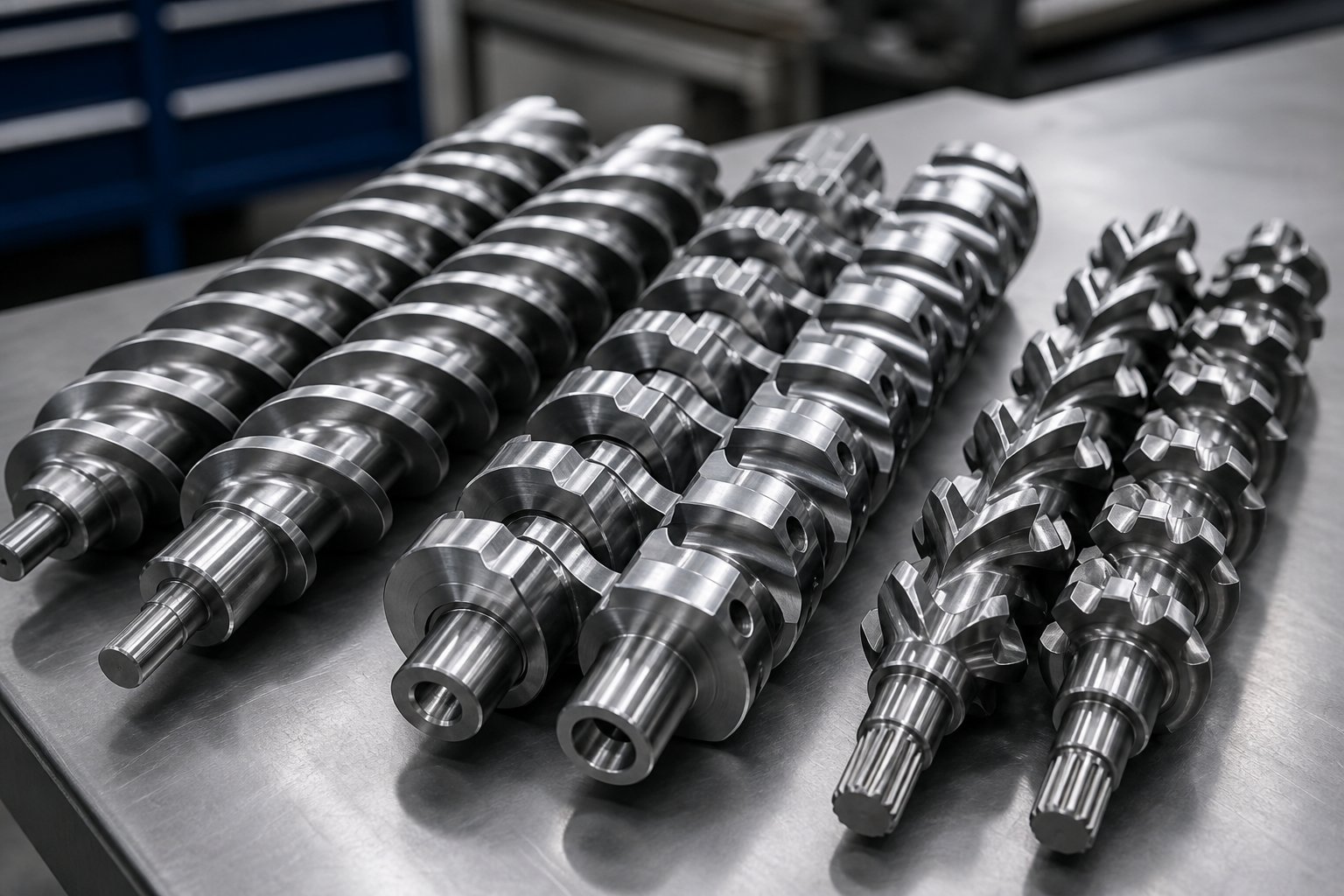
The reason twin screws are so versatile is their modular architecture. Individual screw elements — each with a distinct geometry and function — slide onto a splined shaft and lock into position. Rearrange those elements, and you fundamentally change how the machine conveys, melts, mixes, and pressurizes material. Understanding each element type and how they interact is what separates a competent process setup from a frustrating one.
Conveying, Kneading, and Mixing Elements Explained
Every plastic extruder screw configuration is assembled from three primary element categories. Each one plays a distinct role in the processing sequence.
Conveying elements are the workhorses of material transport. Visually, they resemble traditional helical screw flights, and their job is straightforward: move material forward along the barrel. The key design variable is pitch — the axial distance between consecutive flights. Larger pitch increases theoretical conveying capacity and moves material quickly, while smaller pitch generates more compression and pressure. Engineers typically place coarse-pitch conveying elements in the feed zone for aggressive solids intake, then transition to tighter pitches downstream where pressure building becomes the priority.
Conveying elements also come in reverse pitch variants. Instead of pushing material forward, reverse elements push it backward — creating a localized dam of pressure upstream. This sounds counterproductive until you realize it is exactly how melt seals are formed ahead of vacuum venting ports. Without that pressure barrier, volatile gases cannot be extracted because melt would flood the vent opening.
Kneading blocks are where the real mixing action happens. A kneading block consists of multiple disc-shaped lobes stacked along the shaft, each offset by a defined angular increment called the stagger angle. This angle is the single most influential variable in determining mixing behavior.
Here is the relationship in practical terms:
| Stagger Angle | Conveying Effect | Mixing Type | Shear Intensity |
|---|---|---|---|
| 30° | Strong forward | Primarily distributive | Moderate |
| 45° | Moderate forward | Balanced distributive/dispersive | High |
| 60° | Weak forward | Primarily dispersive | Very high |
| 90° (neutral) | Zero net conveying | Maximum dispersive | Extreme |
A 30° forward kneading block gently splits and recombines the melt stream — ideal for distributing a pre-dispersed colorant evenly throughout the matrix without generating excessive heat. A 90° neutral kneading block, on the other hand, creates minimal net conveying, forcing material to oscillate back and forth across the discs. This maximizes residence time in the mixing zone and generates the intense shear stress needed to fracture stubborn filler agglomerates like carbon black clusters or nano-silica aggregates.
Disc width matters too. Narrower kneading discs create more frequent changes in cross-sectional flow patterns, increasing local pressure fluctuations and boosting dispersive action. Wider discs produce smoother flow paths that favor gentler distributive mixing with lower stress.
Specialized mixing elements fill the gap between conveying elements and kneading blocks. Gear-type (toothed) mixing elements, for instance, repeatedly split and recombine the melt through interlocking teeth rather than disc offsets. They deliver excellent distributive mixing — spreading additives evenly throughout the polymer — while strictly controlling melt temperature rise. This makes them particularly valuable for heat-sensitive formulations where aggressive kneading blocks would cause degradation.
How Screw Configuration Affects Processing Outcomes
The beauty of modular twin screws is that you are not locked into a single processing profile. Slide the elements off the splined shaft, rearrange them, and the same extruder becomes a different machine. But that flexibility also means the configuration space is enormous — and poor choices carry real consequences.
Every element you add or reposition changes four interconnected outcomes:
- Residence time: Adding more kneading blocks or reverse elements increases how long material stays in the barrel. Longer residence time improves mixing completeness but raises the risk of thermal degradation for sensitive polymers.
- Fill level: Restrictive elements (reverse pitch, neutral kneading blocks) back up material upstream, raising the local fill level. Fully filled zones are necessary for effective mixing and pressure generation, but overfilling can spike torque and flood vent ports.
- Melt temperature: Every kneading block and every reverse element adds mechanical energy that converts to heat through viscous dissipation. An overly aggressive plastic extrusion screw profile can push melt temperatures well beyond set points, even with active barrel cooling.
- Mixing quality: Both the type and sequence of mixing elements determine whether you achieve adequate dispersion and distribution. Placing dispersive elements too early — before the polymer is fully molten — wastes energy and can damage filler morphology. Placing them too late may mean the melt viscosity has dropped too low to transmit enough shear stress to break agglomerates.
Given these tradeoffs, process engineers typically work backward from product requirements. The following guidelines cover the most common configuration strategies:
- Gentle blending (polymer alloys, masterbatch letdown): Use predominantly forward conveying elements with short sections of low-stagger (30°) kneading blocks. Prioritize distributive mixing — you want spatial uniformity without aggressive particle size reduction. Keep total kneading block length short to minimize melt temperature rise.
- Intensive filler dispersion (carbon black, mineral fillers, nano-additives): Incorporate one or two zones of high-stagger (60° to 90°) kneading blocks positioned after the melting zone where melt viscosity is high enough to transmit shear stress effectively. Narrower disc widths within these blocks boost dispersive intensity by increasing pressure fluctuations across short distances. Follow each dispersive zone with forward conveying elements to allow the melt to cool slightly before the next processing stage.
- Devolatilization (moisture removal, solvent stripping): Place reverse-pitch conveying elements or reverse kneading blocks immediately upstream of each vacuum vent port. These create a melt seal — a fully filled plug of material that prevents air from being drawn into the barrel through the vent. Downstream of the vent, use large-pitch conveying elements to reduce fill level and expose maximum melt surface area for volatile escape.
- Reactive extrusion (grafting, polymerization, crosslinking): Design extended mixing zones with a combination of distributive elements (gear mixers, low-stagger kneading blocks) to ensure thorough catalyst or monomer distribution, followed by long conveying sections that provide the residence time needed for the reaction to reach target conversion. Multiple temperature-controlled barrel zones let you create the precise thermal profile the reaction kinetics demand.
A critical point that reference sources consistently emphasize: screw design rarely relies on kneading blocks alone. The most effective configurations combine conveying elements, kneading blocks, and specialized mixing elements into an integrated transport-melt-mix-degas-meter sequence tailored to the specific material system. Relying on conveying elements alone produces poor additive distribution, while overloading the profile with kneading blocks drives up melt temperature and torque without proportional mixing improvement.
The takeaway for anyone evaluating or operating a twin screw extruder machine is simple: the screw configuration is not a set-and-forget decision. It is a design variable that should be revisited every time you change formulations, adjust throughput targets, or troubleshoot quality issues. And because the elements are modular, reconfiguration is a matter of hours, not weeks — making it one of the fastest and lowest-cost process improvements available.
Of course, even a perfectly configured screw profile can only perform within the constraints set by the machine's fundamental specifications — screw diameter, L/D ratio, torque capacity, and speed range. These numbers define the outer boundaries of what any configuration can achieve.
Key Technical Specifications That Drive Performance
A spec sheet for a twin screw extruder machine can list dozens of numbers — screw diameter, L/D ratio, maximum RPM, torque rating, motor power, number of barrel zones. Stare at two competing datasheets side by side, and it is easy to feel overwhelmed. Which numbers actually matter? Which ones are marketing padding? And how do they connect to the processing outcomes you care about — throughput, melt quality, mixing intensity, and formulation flexibility?
The answer starts with understanding three specification clusters that, more than anything else, define what a twin screw extruder can and cannot do.
Screw Diameter and L/D Ratio
Screw diameter is the single most important sizing parameter. It sets the machine's volumetric capacity, determines available torque through shaft cross-section, and governs scale-up relationships between different extruder sizes. Industry offerings span a wide range: a benchtop twin screw extruder for early-stage research may feature screws as small as 12 to 16 mm in diameter, while a full production machine can run 75 mm, 95 mm, 135 mm, or larger.
The L/D ratio — screw length divided by screw diameter — tells you how much processing real estate is available along the barrel. A typical range runs from 20:1 to 48:1, with some high-performance configurations reaching 52:1 or even 60:1. Think of L/D as a budget of barrel space you can allocate to different processing tasks:
- Short L/D (20:1 to 28:1): Sufficient for simple compounding tasks — color masterbatch, basic blending, or processing thermally sensitive materials where you want the shortest possible exposure to heat. These ratios keep residence time short and mechanical energy input low.
- Medium L/D (28:1 to 36:1): The most versatile range. There is enough barrel length for a full solid-conveying zone, a dedicated melting section, one or two mixing zones, and a metering section. This covers engineering plastics compounding, moderate filler loading, and most standard applications.
- Long L/D (36:1 to 48:1+): Required when the process demands multiple functional zones — for example, an initial mixing section, followed by a side feeder port for downstream filler addition, then a second mixing zone, and finally one or two vacuum vent ports for devolatilization. Reactive extrusion, heavily filled compounds, and solvent-stripping applications almost always need L/D ratios of 36:1 or longer to accommodate the required processing stages.
A critical nuance: longer L/D is not automatically better. Every additional barrel diameter of length adds residence time and mechanical energy input. For thermally sensitive polymers — PLA, certain medical-grade resins, or halogenated flame retardant compounds — an unnecessarily long barrel can cause degradation that no amount of cooling will fix. The right L/D ratio matches the process complexity, not the marketing brochure.
Torque, RPM, and Specific Energy Input
If screw diameter and L/D define the machine's geometry, torque and RPM define its muscle.
Torque density — the maximum torque transmitted per unit of screw shaft cross-sectional area — is the specification that separates entry-level machines from high-performance extruders. Higher torque density means the screws can process higher-viscosity melts, push through more restrictive screw configurations, and handle heavily filled systems without tripping the safety clutch. Modern high-speed energy input (HSEI) twin screw extruders achieve their torque ratings through robust splined shaft designs and advanced metallurgy, with the shaft cross-section and manufacturing method ultimately dictating the maximum torque that can be imparted into the process.
The relationship between torque and RPM is governed by a straightforward equation: for a given motor power rating (in kW), increasing the maximum screw speed requires a proportional reduction in per-shaft torque, and vice versa. A machine geared for 600 RPM with a 200 kW motor delivers the same shaft torque as the same machine geared for 1200 RPM with a 400 kW motor. If your process never exceeds 600 RPM, the higher-speed configuration offers no torque advantage — it simply costs more.
Maximum RPM ranges vary dramatically by machine class. Laboratory extruders and lab scale twin screw extruders typically run up to 600 to 800 RPM, while production-scale HSEI machines can reach 1200 RPM or higher. Higher screw speeds increase shear rate and throughput but also raise melt temperature through viscous dissipation — a tradeoff you must manage through barrel cooling and screw element selection.
Specific mechanical energy (SME) ties everything together. SME measures how many kilowatt-hours of mechanical work the motor inputs per kilogram of material processed. It is calculated from applied motor power divided by mass throughput:
SME (kWh/kg) = [Motor Power (kW) x % Torque x (RPM / Max RPM) x Gearbox Efficiency] / Throughput (kg/hr)
Why does this matter? Because SME is the most reliable single number for characterizing processing intensity — and for scaling a process between machines of different sizes. If you develop a formulation on a laboratory twin screw extruder at an SME of 0.20 kWh/kg, you can target that same value on a production machine to achieve comparable mixing and melt quality, even though the screw diameter, RPM, and throughput are all different. Tracking SME also helps troubleshoot drift: if a product that normally runs at 0.25 kWh/kg suddenly drops to 0.16 kWh/kg with no hardware or process changes, the feedstock itself has almost certainly changed.
Specification Benchmarks by Machine Class
One of the most practical things you can do before evaluating quotes is build a mental map of what "normal" looks like for each machine class. The following table consolidates industry-standard specification ranges across laboratory extruders, pilot-scale machines, and full production units — giving you a baseline for interpreting any manufacturer's datasheet.
| Specification | Laboratory Scale Extruder | Pilot-Scale Extruder | Production-Scale Extruder |
|---|---|---|---|
| Screw Diameter | 12 – 27 mm | 27 – 50 mm | 50 – 135 mm (and beyond) |
| Typical L/D Ratio | 24:1 – 40:1 | 32:1 – 44:1 | 32:1 – 48:1 (up to 60:1) |
| Max Screw Speed (RPM) | 600 – 1000 | 600 – 1200 | 400 – 1200+ |
| Motor Power | 2.2 – 7.5 kW | 11 – 55 kW | 55 – 800+ kW |
| Typical Throughput | 0.5 – 15 kg/hr | 15 – 200 kg/hr | 200 – 20,000+ kg/hr |
| Temperature Zones | 4 – 8 | 8 – 10 | 8 – 14+ |
| Primary Use | Feasibility studies, formulation development, material screening | Process validation, scale-up studies, customer samples, small production runs | Continuous commercial production, high-volume compounding |
A few patterns worth noting. Laboratory extruders — particularly lab scale extruders in the 16 to 20 mm diameter class — often feature L/D ratios of 40:1, which is proportionally longer than many production machines. This is deliberate: a longer L/D on a small-diameter machine compensates for reduced volume and gives researchers enough barrel length to replicate multi-zone processing profiles that a 65 mm production extruder achieves at 36:1. It also improves scale-up correlation by maintaining geometric similarity in terms of available processing stages.
Motor power on a laboratory scale extruder may seem modest at 2 to 7 kW, but when expressed as power per unit of free volume, lab machines often match or exceed the energy density of their production counterparts. That is what allows a 20 mm lab scale twin screw extruder processing 10 kg/hr to generate the same specific mechanical energy as a 75 mm machine running at 2,000 kg/hr — making formulation transfer between scales predictable rather than speculative.
Finally, notice the overlap zone between pilot-scale and production-scale machines in the 40 to 50 mm diameter range. This is not accidental. Many operations use a 50 mm twin screw extruder as both a pilot development tool and a specialty production unit for low-volume, high-value compounds. The versatility of that size class makes it a popular first investment for companies entering the compounding business.
Specifications tell you what a machine can do. But knowing what your specific application requires — which polymers, which fillers, which processing tasks — is what turns those numbers into a meaningful equipment selection. That connection between machine capability and real-world processing demands is exactly where the discussion heads next.
Processing Tasks and Industry Applications of Twin Screw Extruders
Specifications and screw configurations define what a twin screw extruder machine can do. But the reason manufacturers invest in this equipment — and the reason it justifies a premium over simpler alternatives — is the sheer range of processing tasks it handles at an industrial level. Most buyer's guides list applications as bullet points: "compounding, recycling, reactive extrusion." That tells you almost nothing about how the machine accomplishes each task or why a particular setup matters for your product quality. Let's go deeper.
Compounding and Filled Polymer Systems
Compounding is the most widespread application for a twin screw compounding extruder, and it is also one of the most demanding. The fundamental goal sounds simple: blend fillers, reinforcements, or additives into a polymer matrix to create a homogeneous compound with targeted mechanical, thermal, or aesthetic properties. In practice, the challenge is enormous — particularly when filler loading climbs to 50%, 60%, or even 70-80% by weight in high-mineral masterbatch formulations.
Consider a typical calcium carbonate or talc-filled polyolefin compound. The mineral filler arrives as a fine powder with low bulk density, meaning it entrains a significant volume of air. A compounding twin screw extruder handles this through a carefully staged approach: the polymer pellets enter through the main feed hopper, melt in the first barrel zones, and then the mineral filler is introduced downstream through one or more twin-screw side stuffers. This downstream addition strategy is critical for two reasons. First, it avoids compacting dry filler into the unmelted polymer — which can create dense agglomerates that survive the entire mixing process and remain as defects in the final product. Second, it protects upstream barrel sections from abrasive wear when processing fillers like glass fiber or mineral reinforcements.
Imagine glass fiber compounding as an example. The fibers are brittle and abrasive — feeding them through the main hopper would expose the entire process section to wear while also breaking fibers prematurely during melting. Instead, they enter through a side feeder positioned after the melting zone, where they are gently incorporated into an already-molten polymer matrix. The screw elements in the incorporation zone use moderate stagger angles — typically 30° to 45° kneading blocks — to wet the fibers and distribute them without excessive breakage.
For highly filled compounds, air management becomes the hidden bottleneck. As industry research from Dow emphasizes, every side feeder introduces entrained air along with the filler powder. If that air is not vented properly, it can flood back through vent ports — expelling filler powder, creating housekeeping hazards, and destabilizing the process. Successful high-fill compounding requires back vents upstream of each side feeder and front vents downstream of each incorporation zone, with screw elements arranged to maintain partially filled (starve-fed) barrel sections that allow air to escape without carrying filler particles along with it.
A polymer extruder designed for these tasks also benefits from high free volume — the open space between screw flights and barrel wall. Extruders with a high Do/Di ratio (outer screw diameter to inner screw diameter), ideally 1.65 or higher, create deeper screw channels that accommodate more filler per revolution, directly increasing throughput capacity for filled systems.
Reactive Extrusion and Devolatilization
What if the extruder barrel could serve as a chemical reactor? That is precisely what reactive extrusion accomplishes. Instead of merely melting and mixing, the twin screw extruder performs chemical reactions — grafting, polymerization, crosslinking, or chain extension — inside the barrel while material flows continuously from feed to die.
A common industrial example is producing PP-g-MA (polypropylene grafted with maleic anhydride), a compatibilizer used in multilayer packaging and filled engineering compounds. The base PP resin, maleic anhydride monomer, and a peroxide initiator enter the extruder, and the grafting reaction occurs within dedicated mixing zones where temperature and residence time are precisely controlled. The screw plastic extruder configuration for reactive processes typically features extended mixing sections — forward and neutral kneading blocks that ensure thorough catalyst distribution — followed by long conveying zones that provide the dwell time needed for the reaction to reach target conversion rates.
Temperature control is especially demanding. Many reactive extrusion processes are exothermic, generating significant heat that must be managed through barrel cooling to prevent thermal runaway and material degradation. Barrel temperature profiles follow a deliberate pattern: lower temperatures in the feed and preheating zones (120-160°C), elevated temperatures in the reaction zone (180-260°C), and reduced temperatures in the venting zone (160-200°C) to stabilize the product before discharge.
Devolatilization is the natural complement to reactive extrusion — and it is equally important in standard compounding. When you need to strip moisture from hygroscopic polymers, remove residual solvents from solution-based processes, or extract unreacted monomers after a grafting reaction, the twin screw extruder handles it through vacuum venting ports positioned along the barrel.
The mechanism is elegant. Reverse-pitch screw elements or reverse kneading blocks create a melt seal — a fully filled plug of material — immediately upstream of each vent port. This seal prevents atmospheric air from being drawn inward. Downstream of the seal, the screw transitions to large-pitch conveying elements that reduce fill level, expose maximum melt surface area, and allow volatile compounds to flash off under vacuum (typically -0.09 MPa or stronger). Multi-stage venting — two or even three sequential vent ports with melt seals between them — achieves volatile removal rates that a single vent cannot match.
Pelletizing, Recycling, and Direct Extrusion Applications
After the material has been compounded, reacted, or devolatilized, it needs to go somewhere. For the majority of plastic twin screw extruder operations, the destination is a pelletizing system — converting the continuous melt strand into uniform granules that can be stored, shipped, and reprocessed on downstream equipment.
Three pelletizing methods dominate industrial practice:
- Strand pelletizing: The melt exits the die as multiple continuous strands, passes through a water bath for cooling, and enters a strand cutter that chops the solidified strands into cylindrical pellets. This is the simplest and most economical approach, well-suited for general compounding and moderate throughput rates.
- Underwater pelletizing: The melt is cut directly at the die face by rotating blades while submerged in a flow of temperature-controlled water. Pellets solidify almost instantly into spherical or lenticular shapes, making this method ideal for high-throughput production and materials that require rapid quenching — such as low-viscosity polyamides or hot-melt adhesives. A screw extruder granulator configured for underwater pelletizing delivers consistent pellet geometry at rates that can exceed several tons per hour.
- Water ring pelletizing: A hybrid approach where the die face cutter operates in a ring of circulating water rather than full submersion. It offers faster startup and simpler maintenance than underwater systems, making it a popular choice for mid-range throughput applications.
Recycling represents one of the fastest-growing application areas for twin screw extrusion technology. Post-consumer and post-industrial plastic waste rarely arrives as a clean, single-polymer stream. Instead, recyclers face mixed-polymer bales containing contaminants — paper labels, adhesive residues, residual food matter, and incompatible polymer fractions. The twin screw extruder's combination of intense mixing, precise temperature control, multi-stage devolatilization, and melt filtration makes it uniquely capable of reprocessing these challenging feedstocks into usable pellets.
Beyond pelletizing, a growing trend involves bypassing the pellet stage entirely. Direct extrusion — feeding the melt from the twin screw extruder directly into a sheet die, film die, profile die, or fiber spinning system — eliminates an entire remelting step, saving energy and reducing thermal history on the polymer. This approach is gaining traction in sheet extrusion, cast film production, and specialty profile manufacturing where material properties benefit from minimal heat exposure.
To put these applications in perspective, here are the most common industrial uses of twin screw extruders ranked by approximate global processing volume:
- Polymer compounding (filled systems, color concentrates, engineering blends)
- Masterbatch production (pigment, additive, and filler concentrates)
- Plastic recycling (post-consumer and post-industrial reprocessing)
- Reactive extrusion (grafting, chain extension, controlled degradation)
- Devolatilization (solvent removal, moisture stripping, monomer extraction)
- Direct extrusion (sheet, film, profile, and fiber production)
- Food and pharmaceutical processing (snack extrusion, hot-melt extrusion for drug delivery)
What stands out across every one of these applications is a common thread: the extruder for polymer processing is only as effective as the complete system around it — feeders, side stuffers, venting, die design, and downstream equipment all contribute to product quality. The twin screw extruder provides the mixing and thermal control at the core, but integrating it into a well-designed production line is what turns capability into consistent, profitable output.
Given the breadth of these applications, a natural question surfaces: could a simpler, less expensive single screw extruder handle the same tasks? In some cases it can — and knowing exactly where that boundary falls is essential before committing to a purchase.
Twin Screw vs Single Screw Extruder: Which One Do You Actually Need?
That boundary between "twin screw territory" and "single screw territory" is where many purchasing decisions go wrong. Buyers either overspend on a double screw extruder machine they don't fully need, or they underinvest in a single screw system that can't deliver the mixing quality their formulation demands. The problem? Most comparison resources list surface-level differences without explaining the underlying mechanics that drive those differences. Let's fix that.
Working Principle and Mixing Mechanism Differences
The fundamental gap between these two machine types starts at the physics level — how each one moves and transforms material.
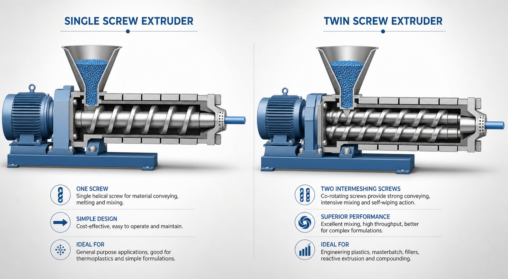
A single screw extruder relies on drag flow. The rotating screw creates friction between the material, the screw surface, and the barrel wall. That friction drags material forward. Melting occurs primarily through a "solid bed" mechanism: a compact plug of unmelted polymer presses against the heated barrel wall, forming a thin melt film that gradually consumes the solid bed as it moves downstream. This process is effective for pre-compounded, thermally stable resins — but it is inherently limited in how thoroughly it can mix or redistribute material across the channel cross-section.
Twin screw extruders work on a fundamentally different principle. In a co-rotating intermeshing design, material is positively displaced from one screw to the other at every point of engagement. Rather than relying on friction to push the melt forward, the intermeshing geometry physically transfers material between screws, creating complex flow patterns that fold, stretch, and recombine the melt stream repeatedly.
This difference produces three practical consequences that matter to process engineers:
- Superior dispersive and distributive mixing: The repeated material transfer between screws subjects every particle to high-shear zones multiple times. Filler agglomerates get broken apart (dispersive mixing), and additives get spread uniformly throughout the matrix (distributive mixing). Single screw designs simply cannot replicate this level of homogenization because material tends to circulate within the same channel position.
- Self-wiping action: Each screw's flights continuously scrape the other screw's surface, virtually eliminating dead zones and stagnant material. This keeps residence time distribution narrow and consistent — critical for heat-sensitive materials where even a small pocket of overcooked polymer creates defects. Single screw extruders have no equivalent mechanism, and material near the barrel wall can linger significantly longer than material at the screw root.
- Starve-fed operation: Twin-screw extruders decouple feed rate from screw speed, letting engineers independently control throughput and shear intensity. A single screw extruder is flood-fed by default — feed rate and screw speed are inherently linked, limiting process flexibility.
Throughput, Flexibility, and Cost Considerations
Does superior mixing mean the double screw extruder always wins? Not necessarily. The right answer depends on what you're processing and how much flexibility you need.
Single screw extruders excel at high-volume, straightforward processing tasks. Film blowing, pipe extrusion from pre-compounded pellets, sheet extrusion of commodity resins — these are applications where the material arrives already formulated, and the extruder's job is simply to melt it uniformly and pump it through a die at a stable rate. For these tasks, a single screw machine delivers reliable output at lower capital cost, lower energy consumption, and simpler maintenance. There is no mixing challenge to solve, so the twin screw's greatest strengths go unused.
Twin screw extruder machines justify their higher investment when the processing task demands formulation flexibility, intensive mixing, or multi-stage processing. If you compound filled engineering plastics one week and switch to a reactive grafting formulation the next, a modular twin screw platform handles both without hardware changes beyond screw element rearrangement. A single screw machine would require purpose-built mixing sections — static mixers, barrier screws, Maddock elements — and still fall short of the mixing intensity a twin screw achieves natively.
Cost differences extend well beyond the purchase price. Twin-screw extruders consume more power per kilogram for equivalent throughput and require more sophisticated gearboxes, which are expensive to repair. Their modular screw elements and segmented barrels, while offering unmatched flexibility, also introduce more wear surfaces and more replacement parts over the machine's lifetime. Single screw machines, with their monolithic screw and simpler drive trains, generally cost less to maintain — though lower upfront cost does not always mean lower long-term cost when factoring in scrap rates, quality rejects, and limited production versatility.
Decision Framework for Machine Selection
Rather than defaulting to "buy the twin screw because it's better," use the comparison below to map your actual processing needs against each machine type's strengths. This table covers the dimensions that most directly influence your return on investment.
| Dimension | Single Screw Extruder | Twin Screw (Double Screw) Extruder |
|---|---|---|
| Mixing Capability | Moderate — adequate for pre-compounded materials; limited distributive and dispersive mixing | Excellent — superior distributive and dispersive mixing; handles multi-component systems |
| Throughput Range | Moderate to high for simple melt-pumping applications | Wide range — lab scale (0.5 kg/hr) through production scale (20+ tons/hr) |
| Capital Cost | Lower — simpler gearbox, single screw, less complex barrel | Higher — precision gearbox, modular screw elements, segmented barrel |
| Operating Cost (Energy) | Lower per kilogram for simple extrusion tasks | Higher per kilogram, but lower cost per kilogram of qualified product for complex formulations |
| Material Flexibility | Limited — best with consistent, pre-formulated pellets | High — handles powders, fibers, liquids, mixed streams, and variable feedstocks |
| Maintenance Complexity | Low — fewer wear components, simpler drive system | Moderate to high — modular elements require periodic inspection and replacement |
| Ideal Applications | Film blowing, pipe extrusion, profile extrusion (pre-compounded), simple sheet production | Compounding, masterbatch, reactive extrusion, recycling, devolatilization, direct extrusion of filled systems |
A practical shortcut: if your raw material arrives as ready-to-melt pellets and you're producing a single product family, screw extruders with a single-screw design will likely serve you well at lower total cost. The moment your process involves blending raw ingredients, dispersing fillers, removing volatiles, or switching between formulations, twin-screw extruders become the only realistic choice — and their higher purchase price pays for itself through processing capability that a single screw simply cannot match.
Whichever type you select, both machines share a common reality: screws and barrels wear over time, and how you manage that wear directly determines uptime, product consistency, and long-term profitability.
Maintenance, Wear Issues, and Troubleshooting Best Practices
Screws and barrels don't fail all at once. They degrade gradually — and the operators who catch that degradation early save thousands of dollars in unplanned downtime and rejected product. Yet most twin screw extruder resources focus exclusively on process optimization and never mention what happens to the hardware after six months, a year, or five years of continuous production. That silence is costly. According to a Plastics Industry Association report, 60% of twin screw extruder failures trace back to improper maintenance of extruder screw and barrel components. Let's close that knowledge gap.
Common Wear Patterns in Screws and Barrels
Three distinct wear mechanisms attack the twin screw barrel and screw elements during operation. Each one leaves a different signature — and each demands a different response.
Abrasive wear is the most common culprit. Every time mineral fillers like calcium carbonate, glass fiber, or talc travel through the barrel, they act like microscopic sandpaper against metal surfaces. The sharp machined edges of screw flights and kneading discs gradually become rounded, smooth, and occasionally polished. The barrel bore widens at high-wear points — particularly in kneading zones where fill levels and pressures are highest. What makes abrasive wear tricky is that it correlates with total material throughput, not calendar time. An extruder running 24/7 on a 60% CaCO3 compound will wear dramatically faster than the same machine processing unfilled resin on a single shift.
Adhesive wear occurs when metal surfaces rub directly against each other without a protective melt film between them. You'll notice this pattern most often during startups and shutdowns — moments when the barrel isn't yet filled with molten polymer. If screws rotate at high speed without sufficient material present, the shafts can deflect and contact each other or the barrel wall. The result? Flattened flight tips, score marks on the barrel wall, and scratches on the flanks and roots of screw elements. Best practice is to reduce screw speed to an idle pace — around 100 RPM or lower — whenever the barrel extruder runs without material flow.
Corrosive wear targets the metal itself through chemical attack. Flame retardants that release hydrobromic or hydrochloric acid at processing temperatures, acidic additives, and even condensation forming on chilled barrel sections can pit and dimple screw and barrel surfaces. Corrosive wear is less common than abrasive damage but far more insidious because it undermines surface integrity at a microscopic level, accelerating the rate of abrasive wear on already-compromised surfaces.
Regardless of the mechanism, the symptoms converge: increased clearance between screw flights and the barrel wall, reduced conveying efficiency (you'll see throughput drop at the same screw speed and feed rate), degraded mixing quality as material slips past worn flights instead of being positively displaced, and — eventually — visible defects in the finished product. When your process needs higher RPM or more aggressive kneading blocks just to match yesterday's output quality, wear is almost certainly the root cause.
Preventive Maintenance and Troubleshooting Guide
Waiting for visible product defects before inspecting the twin screw and barrel is a reactive strategy that always costs more than it saves. A structured preventive maintenance schedule catches wear in its early stages — when component replacement is planned and affordable, not emergency and disruptive.
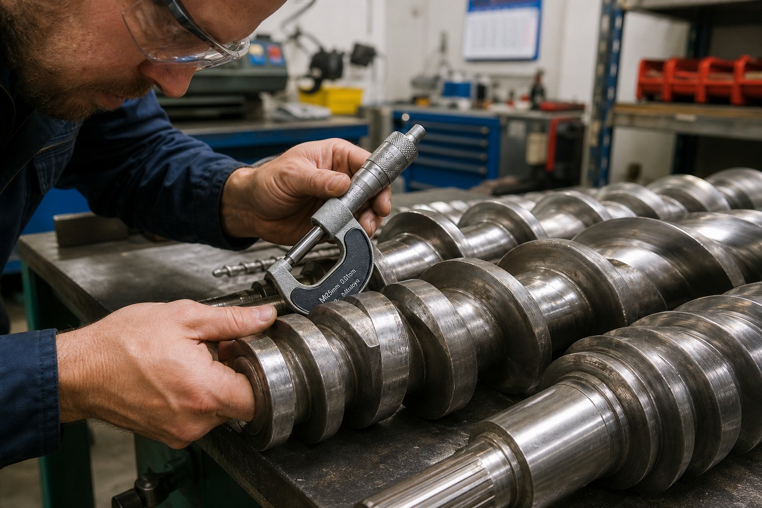
- Monthly — screw element visual inspection: Pull the screws and visually inspect kneading blocks and high-shear conveying elements for rounding, surface scoring, or discoloration. Measure critical flight diameters with a micrometer and compare to original dimensions. Industry guidance suggests that screw elements nearing 5% reduction from starting outer diameter across three-quarters of their length are approaching the replacement threshold.
- Monthly — barrel bore measurement: Use a bore gauge or telescoping gauge to check internal diameter at key points — particularly in kneading zones and side feeder openings where abrasive wear concentrates. A barrel liner showing approximately 5% increase in bore diameter over a length of 1D signals the need for liner replacement or barrel reconditioning.
- Quarterly — gearbox oil analysis: Submit oil samples for particle count and spectrometric analysis. Elevated iron or bronze particle concentrations indicate gear or bearing wear well before you hear unusual noise or feel vibration changes. Replace oil per the manufacturer's recommended interval — or sooner if analysis flags contamination.
- Quarterly — heating and cooling system checks: Verify that all barrel heater bands deliver rated wattage using a clamp meter. Check cooling water flow rates and inspect internal cooling channels for scale buildup. A heater that has lost 20% of its output silently distorts your temperature profile, and operators often compensate by adjusting adjacent zones — masking the real problem while introducing new ones.
- Annually — complete disassembly and overhaul: Remove all screw elements and barrel liners for thorough dimensional measurement, inspect splined shafts for twist or fatigue cracking, assess thrust bearings and seals, and verify alignment. Proactive maintenance programs of this kind can reduce operating costs by 20-30% compared to reactive, breakdown-driven approaches.
Beyond scheduled inspections, four common operational problems demand immediate troubleshooting attention:
- Output surging: Fluctuating strand or pellet output usually points to inconsistent feed rates or worn conveying elements that can no longer maintain steady pressure at the die. Check gravimetric feeder calibration first, then inspect upstream conveying screws for flight wear.
- Poor mixing quality (uneven color, filler agglomerates, gels): Evaluate whether kneading block configuration still matches the formulation. Worn kneading discs with rounded edges lose dispersive effectiveness. Also verify that screw speed is high enough to generate the required shear — and that the elements haven't been inadvertently rearranged during the last screw pull.
- Barrel overheating (actual melt temperature exceeding set point): This can stem from excessive shear in worn kneading zones (where widened clearances change flow dynamics), blocked cooling channels, or a screw configuration that is too aggressive for the current throughput. Inspect the heater/cooler balance zone by zone and compare actual temperature readings against historical baselines.
- Excessive torque spikes: Review feed rate relative to screw speed — an overfilled barrel drives torque up fast. Also consider material viscosity: a new resin lot with higher molecular weight or moisture content can spike torque without any hardware change. If torque remains elevated after adjusting process parameters, suspect a mechanical issue — misaligned screws, seized bearings, or a foreign object lodged between elements.
When to Replace Screw and Barrel Components
The replacement decision is straightforward in principle: components need replacing when a reduction in output and/or quality can be observed that cannot be corrected by process adjustments alone. In practice, the line is blurrier.
A screw element worn 3% below nominal diameter may still produce acceptable compound — but at a higher screw speed and energy cost than a new element would require. A barrel liner worn 4% above nominal bore still conveys material — but leakage flow past the flights reduces mixing efficiency, forcing you to add kneading blocks that raise melt temperature and risk degradation. The real question is not "does it still work?" but "is the cost of running worn components — in energy, scrap, quality risk, and slower throughput — greater than the cost of replacing them?"
For most production environments, the answer tips toward replacement when any of these conditions appear:
- Flight diameter has decreased by 5% or more over the majority of the element length
- Barrel bore has increased by 5% or more over a span of at least 1D
- Throughput at constant screw speed has dropped measurably (typically 10-15% or more) from baseline
- Product quality — dispersion level, mechanical properties, surface finish — no longer meets specification despite process optimization
- Torque consumption has risen significantly for the same formulation and throughput, indicating the screws are working harder to compensate for lost conveying efficiency
When it's time to source replacement components, quality matters enormously. A low-cost screw element made from inferior steel may cost 30% less upfront but wear out in half the time — doubling the number of line stoppages for element changes over the machine's life. Look for elements manufactured from nitrided steel, powder metallurgy alloys, or tungsten carbide-coated substrates depending on the severity of your wear environment. Barrel liners with bimetallic construction offer a hard, wear-resistant inner surface bonded to a tough structural outer shell — a combination that resists both abrasive and corrosive attack far longer than standard nitrided barrels.
For operations running twin screw extruders in pipe, profile, sheet, pelletizing, or recycling applications, having a reliable sourcing partner for screw and barrel components is just as important as having a good machine. NANHAIYA's screw barrel support for plastic extruder machines serves as a practical resource for extrusion manufacturers and recycling plants that need replacement twin screw and barrel components engineered to match OEM specifications — reducing lead time on critical wear parts and helping keep production lines running at their designed capacity.
Keeping hardware in top condition protects your uptime, but it is only one piece of the total cost picture. The real financial calculus behind owning a twin screw extruder extends well beyond maintenance — into energy efficiency, consumable costs, and the often-overlooked question of how to evaluate the suppliers who build and support these machines.
Total Cost of Ownership and Selecting the Right Partner
Here is the uncomfortable truth about the twin screw extruder price you see on a quote: it represents roughly 40-60% of what you'll actually spend over the machine's productive life. The rest — energy bills, screw and barrel replacements, gearbox overhauls, unplanned downtime, and the opportunity cost of suboptimal output — accumulates quietly, month after month, until it dwarfs the original capital investment. Most twin screw extruder manufacturers lead with machine price because it is the easiest number to compare. But experienced buyers know that total cost of ownership (TCO) is the only metric that tells you whether the investment actually pays off.
Understanding Total Cost of Ownership
Imagine two extruders sitting side by side on a production floor. Machine A cost $350,000 and Machine B cost $250,000. After five years, which one was the better deal? You cannot answer that question without examining the cost layers that unfold after the purchase order ships.
Energy consumption is the single largest ongoing expense. A twin screw extruder's drive motor typically accounts for 70-80% of the line's total power draw, and even small differences in motor efficiency compound over thousands of operating hours. Specific energy — measured in kilowatt-hours per kilogram of processed material — is the metric to watch. A machine consuming 0.25 kWh/kg versus one at 0.30 kWh/kg represents a 20% energy penalty on every kilogram produced. At a throughput of 1,000 kg/hr running 6,000 hours per year, that difference translates to 300,000 kWh annually. At industrial electricity rates, the savings from a more efficient drive can easily reach $20,000 to $40,000 per year — a figure that reshapes the cost comparison between a premium extruder and a budget alternative remarkably fast.
Screw and barrel replacement frequency varies enormously depending on what materials you process. An extruder running unfilled polyolefins may see screw elements last three to five years with minimal wear. The same machine compounding 60% calcium carbonate or glass fiber-reinforced nylon can consume screw elements and barrel liners in 12 to 18 months — or even faster if the metallurgy is substandard. As industry analysis confirms, budget twin screw extruders under $50,000 for typical industrial applications can carry 40% higher cost of ownership over five years due to accelerated screw wear requiring replacement every 12-18 months, greater power draw, and unplanned downtime totaling 10-15% of production time. The quality of the screw element steel — nitrided, bimetallic, or tungsten carbide coated — directly determines how often you stop the line, pull the screws, and install fresh elements.
Gearbox maintenance is the cost most buyers overlook entirely until they receive their first repair invoice. Twin screw extruder gearboxes are precision-engineered to handle enormous torsional loads, and they are among the most expensive single components on the machine. Lubricant analysis at quarterly intervals catches gear wear early. But if you undersize the drive motor — or routinely run above 80% of rated torque — gearbox life shortens dramatically. As Plastics Technology notes, the most common cause of premature gearbox failure is an undersized motor, and selecting a motor that delivers at least 20% more torque than the process demands is standard engineering practice.
Downtime costs are the most dangerous because they are invisible on the balance sheet until they happen. Every hour a production line sits idle — waiting for replacement screw elements, a gearbox repair, or a barrel liner swap — represents lost output, delayed customer shipments, and wasted labor. In high-volume compounding operations, unplanned downtime can cost $5,000 to $15,000 per hour when you factor in lost production, scrap from startup purging, and expedited shipping to recover delivery schedules. The difference between a two-day and a two-week lead time on replacement parts is not a minor procurement detail — it is a five-figure financial event.
The connection between all four cost factors circles back to one variable: component quality. Higher-grade screw elements and barrel liners cost more upfront but wear slower, maintain tighter clearances longer, consume less energy per kilogram (because less material slips past worn flights), and extend the interval between planned shutdowns. When you evaluate the twin screw extruder price against the full cost picture, the machine with the lowest sticker price almost never delivers the lowest five-year TCO.
Evaluating Twin Screw Extruder Manufacturers
The twin screw extruders market includes dozens of manufacturers ranging from global OEMs with fifty-year track records to regional builders offering aggressive pricing. Sorting through that landscape without a structured evaluation framework is how buyers end up with machines that look good on paper but underperform in the plant.
Whether you are purchasing a complete new line or sourcing a twin-screw extruder manufacturer for replacement components, the following criteria separate reliable partners from risky ones:
- Technical support capability: Does the supplier provide application engineering — helping you select screw configurations, optimize process parameters, and troubleshoot production issues? Or do they ship hardware and disappear? A manufacturer that can recommend the right kneading block arrangement for your specific filler system or advise on barrel temperature profiles for a reactive extrusion process adds value that far exceeds the component cost.
- Spare parts availability and lead time: Ask for documented lead times on critical wear parts — screw elements, barrel liners, shaft seals, and gearbox components. If a supplier quotes six to eight weeks for standard screw elements, you need to maintain a larger on-site inventory to avoid production gaps. Shorter lead times reduce your working capital tied up in spare parts.
- Screw element material options: A capable supplier offers a range of metallurgies matched to your processing environment. At minimum, look for nitrided steel (suitable for unfilled or lightly filled systems), bimetallic alloys with nickel- or cobalt-based linings (for moderate abrasion and corrosion), and tungsten carbide coated or solid carbide options (for heavily filled or highly abrasive compounds). A supplier offering only one material grade cannot serve diverse production needs.
- Barrel liner construction: Standard nitrided barrels serve commodity applications, but bimetallic barrel liners — with a wear-resistant alloy centrifugally cast inside a structural steel shell — deliver significantly longer life in demanding environments. According to field data from major processors, bimetallic barrel solutions for high-CaCO3 PVC compounds improve service life by 30-35% compared to standard nitrided alternatives. Verify that your supplier can provide these options.
- Manufacturing precision and quality control: Request documentation on dimensional tolerances for screw elements and barrel bores. Parallelism of screw shafts, concentricity of barrel liners, and surface finish quality all affect processing consistency and component longevity. Suppliers who provide inspection certificates with actual measured values — not just nominal specs — demonstrate a level of quality commitment that translates directly to performance on your production floor.
- After-sales service and responsiveness: How quickly does the supplier respond to technical inquiries? Do they offer on-site support for complex installations or troubleshooting? Can they provide expedited manufacturing for emergency replacement parts? These questions are easy to ask during the quoting phase and difficult to answer once you are in a production crisis.
- Track record and references: Ask for case studies or reference customers in your industry segment. A twin-screw extruder manufacturer with proven installations in your application area — whether that is engineering plastics compounding, PVC profile extrusion, or post-consumer recycling — brings practical experience that generic suppliers lack.
One strategic approach that experienced operations adopt is separating the machine purchase decision from the screw and barrel sourcing decision. Many plants buy their extruder from an OEM but source replacement screws and barrels from specialized component manufacturers who offer equivalent metallurgy, tighter tolerances, shorter lead times, or better pricing than OEM aftermarket channels. This is where having a dedicated screw barrel partner becomes a practical advantage. NANHAIYA, for example, provides screw barrel support for plastic extruder machines across pipe, profile, sheet, pelletizing, recycling, and general processing lines — serving extrusion manufacturers, recycling plants, and technical teams that need reliable replacement components without being locked into a single OEM supply chain.
The value of that flexibility is real. When your compounding extruder's kneading elements wear beyond tolerance at 2 AM on a Thursday and your OEM quotes a six-week delivery, a responsive component partner with the right material grades and precision manufacturing capability is the difference between a weekend repair and a month of degraded production.
Ultimately, the twin screw extruder for sale at the lowest price is never the cheapest option — and the most expensive machine is not automatically the best investment. What determines your return is the intersection of machine capability, component quality, supplier support, and how rigorously you manage the total cost of ownership across the machine's productive life. Buy with that full picture in mind, and the twin screw extruder becomes one of the highest-ROI assets on your production floor. Ignore it, and even the best-spec machine becomes an expensive source of frustration.
Frequently Asked Questions About Twin Screw Extruder Machines
1. What is the difference between a co-rotating and counter-rotating twin screw extruder?
Co-rotating twin screw extruders have both screws spinning in the same direction, producing intense distributive and dispersive mixing with self-wiping action — ideal for compounding, masterbatch, and reactive extrusion. Counter-rotating designs spin screws in opposite directions, creating a gentler calendering effect with lower shear. This makes them better suited for thermally sensitive materials like rigid PVC. Your choice depends on the material's shear sensitivity, required mixing intensity, and throughput targets. Co-rotating machines dominate high-performance compounding, while counter-rotating extruders excel in PVC pipe and profile extrusion.
2. How does a twin screw extruder differ from a single screw extruder?
A single screw extruder relies on drag flow and friction to convey material, offering moderate mixing suited for pre-compounded pellets. A twin screw extruder uses intermeshing screws that positively displace material, achieving superior dispersive and distributive mixing, self-wiping action, and starve-fed operation that decouples feed rate from screw speed. Twin screw machines cost more but handle complex formulations, filled systems, reactive processes, and frequent product changeovers. Single screw extruders are more economical for simple, high-volume tasks like film blowing or pipe extrusion from ready-to-melt pellets.
3. What L/D ratio should I choose for my twin screw extruder?
The ideal L/D ratio depends on your processing complexity. Short ratios (20:1 to 28:1) suit simple compounding and thermally sensitive materials. Medium ratios (28:1 to 36:1) accommodate standard engineering plastics compounding with dedicated melting, mixing, and metering zones. Long ratios (36:1 to 48:1 or higher) are necessary for multi-stage processes involving downstream filler addition, multiple vacuum venting ports, reactive extrusion, or heavy devolatilization. Longer L/D is not automatically better — unnecessary barrel length adds residence time and risks thermal degradation for sensitive polymers.
4. How often should twin screw extruder screws and barrels be replaced?
Replacement intervals vary based on materials processed. Unfilled polyolefins may allow screw elements to last three to five years, while heavily filled compounds with glass fiber or mineral fillers can wear elements in 12 to 18 months. Key replacement indicators include a 5% or greater reduction in screw flight diameter, a 5% increase in barrel bore diameter, measurable throughput loss at constant screw speed (typically 10-15%), or product quality falling below specification despite process optimization. Sourcing high-quality replacement components from specialists like NANHAIYA (nhyscrews.com) helps maintain tight clearances and reduces unplanned downtime.
5. What factors determine the total cost of ownership of a twin screw extruder?
The purchase price typically represents only 40-60% of lifetime costs. Major ongoing expenses include energy consumption (driven by motor efficiency and specific energy per kilogram), screw and barrel replacement frequency (determined by material abrasiveness and component metallurgy), gearbox maintenance, and unplanned downtime costing $5,000 to $15,000 per hour in high-volume operations. Budget machines under $50,000 can carry 40% higher five-year TCO due to faster wear, higher power draw, and more frequent downtime. Investing in quality components — nitrided, bimetallic, or tungsten carbide coated screws and barrels — significantly lowers long-term operating costs.
Written by
Nanhaiya Technical Team
Zhoushan Nanhaiya Plastic Machinery Co., Ltd.
The Nanhaiya technical team supports screw and barrel manufacturing projects through application review, technical communication, custom manufacturing coordination, and production and quality control.
Discuss Your Application
Related Articles
More insights on screw barrel technology and plastics processing.

Extruder Machine Decoded: From Raw Pellet To Finished Product
Oct 6, 2026
Learn how an extruder machine works, compare single-screw vs. twin-screw types, and get expert guidance on specs, troubleshooting, and selection.
Read Article
PE Pipe Making Machine Decoded: From Raw Resin to Flawless Pipe
Oct 4, 2026
Learn how a PE pipe making machine works, from resin to finished pipe. Covers components, material grades, automation, troubleshooting, and buyer selection tips.
Read Article
PVC Profile Making Machine Decoded: From Raw Resin To Profit
Oct 3, 2026
Learn how a PVC profile making machine works — extrusion process steps, key technical parameters, die design, calibration methods, maintenance, and total cost of ownership.
Read ArticleLooking for something else?
Search by material, symptom or product and jump straight to the relevant page.
These are navigation suggestions based on keyword matching — not a quotation, not a delivery commitment, and not a substitute for engineering review. Final specification is confirmed by our engineers against your drawings and processed material.
Need help with screw barrel selection?
Share your machine model, processed material and application. Our team can help with pricing and technical support.