

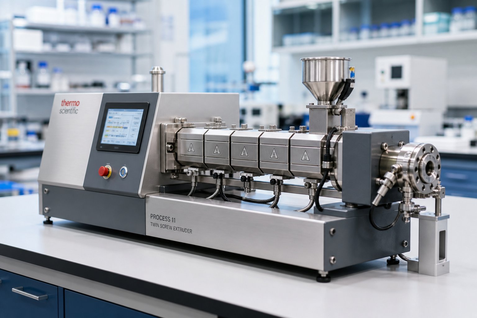
What Is a Laboratory Twin Screw Extruder and Why It Matters
Imagine you have a promising new polymer formulation on the benchtop, but scaling it directly to a production line would burn through thousands of dollars in raw materials — with no guarantee of success. That gap between a small beaker and a factory floor is exactly where the twin screw extruder laboratory setup earns its place.
Defining the Laboratory Twin Screw Extruder
A laboratory twin screw extruder is a continuously operating, modular extrusion platform scaled down for research-level throughputs. It uses two intermeshing screws housed inside a heated barrel to compound, mix, react, and devolatilize materials under controlled, repeatable conditions. Screw diameters typically range from 12 mm to 27 mm, and throughput rates span from a few hundred grams up to several kilograms per hour — a fraction of what production-scale machines handle.
What sets the lab extruder apart from its industrial counterpart is not just size. It is purpose-built for flexibility. Modular barrel sections can be rearranged, screw elements swapped in minutes, and process parameters adjusted across wide ranges. Every run generates process-relevant data — melt temperature, torque, pressure, residence time — that researchers use to understand material behavior before committing to expensive full-scale trials.
Why Twin Screw Extrusion Matters in the Lab
Speed, precision, and material conservation drive the adoption of twin screw extruders in research settings. A single lab-scale trial can consume as little as 200 grams of material, compared to tens of kilograms on a production line. This efficiency lets researchers iterate rapidly through dozens of formulation variations in a single day, accelerating development timelines that once stretched across months.
Lab-scale twin screw extrusion bridges the gap between benchtop formulation and full-scale production by providing process-relevant data at minimal material cost.
The versatility of this platform extends well beyond traditional polymer science. Pharmaceutical researchers rely on it for hot-melt extrusion of amorphous solid dispersions. Food technologists use it to develop plant-based protein textures. Battery material scientists process electrode slurries through it. Sustainable materials researchers compound biopolymer blends with natural fillers. In each case, the laboratory twin screw extruder delivers continuous processing conditions that batch mixers simply cannot replicate — and that distinction matters enormously when the goal is reliable scale-up to manufacturing.
Yet despite its central role, much of the practical knowledge around selecting, configuring, and operating these machines remains scattered or oversimplified. Researchers frequently struggle with questions that go far deeper than basic definitions — questions about which equipment class actually fits their needs, how screw configurations affect outcomes, and what it really takes to translate lab data into production reality.
Micro-Compounder vs Lab Extruder vs Pilot-Scale Equipment
One of the most common sources of confusion — and costly purchasing mistakes — starts with terminology. The terms "micro-compounder," "laboratory extruder," and "pilot-scale extruder" are frequently used interchangeably in catalogs and even academic papers. They are not the same thing. Each equipment class occupies a distinct role in the R&D pipeline, and choosing the wrong one can mean generating data that doesn't translate downstream. Here's how to tell them apart.
Micro-Compounders for Ultra-Small Sample Volumes
When material is scarce — think newly synthesized polymers, expensive pharmaceutical APIs, or novel nanofillers — micro-compounders are often the first stop. These instruments typically handle batch volumes of just 5 to 15 cc, making them ideal for early-stage screening where only a few grams of material exist. A study published in Polymers demonstrated that a 15 mL twin-screw micro-compounder could effectively prepare EPDM/carbon black and EPDM/silica composites for R&D screening, achieving dispersion quality that matched or exceeded conventional Banbury mixing — all with a fraction of the material.
The key distinction, however, is that micro-compounders are recirculating systems. Material cycles through the screws repeatedly within a closed chamber rather than flowing continuously from feed throat to die. This recirculation allows researchers to simulate different residence times and achieve thorough mixing at very small volumes, but it does not replicate the continuous processing conditions found on a production line. You'll get useful material property data, but the process parameters won't transfer directly to a continuous extruder.
Laboratory Extruders for Continuous Small-Batch Processing
This is where the lab scale twin screw extruder fills a critical gap. Unlike micro-compounders, a laboratory scale extruder operates continuously — raw material enters at the feed end and exits as a finished extrudate at the die, just like a production machine. Screw diameters typically range from 12 mm to 27 mm, delivering throughputs from a few hundred grams to several kilograms per hour.
Why does continuous operation matter so much? Because it generates process-relevant data. Every parameter you measure on a lab scale extruder — specific mechanical energy, residence time distribution, melt temperature at the die, barrel fill level — has a direct counterpart on production equipment. That makes the laboratory extruder the natural choice when your research goal extends beyond material screening to formulation optimization and scale-up. Many benchtop twin screw extruder models in this class are compact enough to fit on a standard lab bench, yet they incorporate the same modular screw and barrel architecture used in full-size production machines.
Pilot-Scale Extruders and the Transition to Production
Pilot-scale extruders occupy the space between R&D and manufacturing. With screw diameters often ranging from 27 mm to 40 mm or larger, these machines handle throughputs of tens of kilograms per hour — enough to produce customer samples, run extended process validation trials, or support small-batch production. A benchtop extruder won't generate the volume needed for downstream testing like injection molding or film blowing trials; a pilot-scale machine will.
Pilot systems also serve as the proving ground for scale-up assumptions. Parameters optimized on a laboratory extruder can be validated at pilot scale before committing to full production equipment, reducing risk significantly.
The following table summarizes the practical differences across all three equipment classes:
| Equipment Class | Typical Screw Diameter | Throughput Range | Operation Mode | Best-Fit Use Case |
|---|---|---|---|---|
| Micro-Compounder | Conical, 5–15 cc batch volume | Grams per batch | Batch (recirculating) | Early-stage screening with scarce or expensive materials |
| Laboratory Extruder | 12 mm – 27 mm | 0.2 – 10 kg/h | Continuous | Formulation optimization and process development for scale-up |
| Pilot-Scale Extruder | 27 mm – 40 mm+ | 10 – 100 kg/h | Continuous | Process validation, customer samples, and small-batch production |
Picking the right class comes down to one question: what will you do with the data? If you need to know whether a formulation concept works at all, a micro-compounder is efficient and material-sparing. If you need process parameters that will hold up during scale-up, a lab scale extruder operating in continuous mode is essential. And if you need to prove those parameters at a volume relevant to manufacturing, pilot-scale equipment bridges the final gap.
Understanding these distinctions is the first step. The next decision — which screw configuration to specify inside that machine — shapes everything from mixing intensity to the types of research you can pursue.
Co-Rotating vs Counter-Rotating Twin Screw Configurations in the Lab
Screw configuration is arguably the single most consequential decision a researcher makes when setting up a twin screw extruder laboratory. Two screws can rotate in the same direction or in opposite directions — and that fundamental difference cascades into everything from mixing intensity and shear history to the types of materials you can process reliably. Yet most resources treat this as a production-floor topic, glossing over how these configurations behave at laboratory scale where material volumes are small, experimental precision is paramount, and research flexibility matters more than raw throughput.
Co-Rotating Intermeshing Configuration
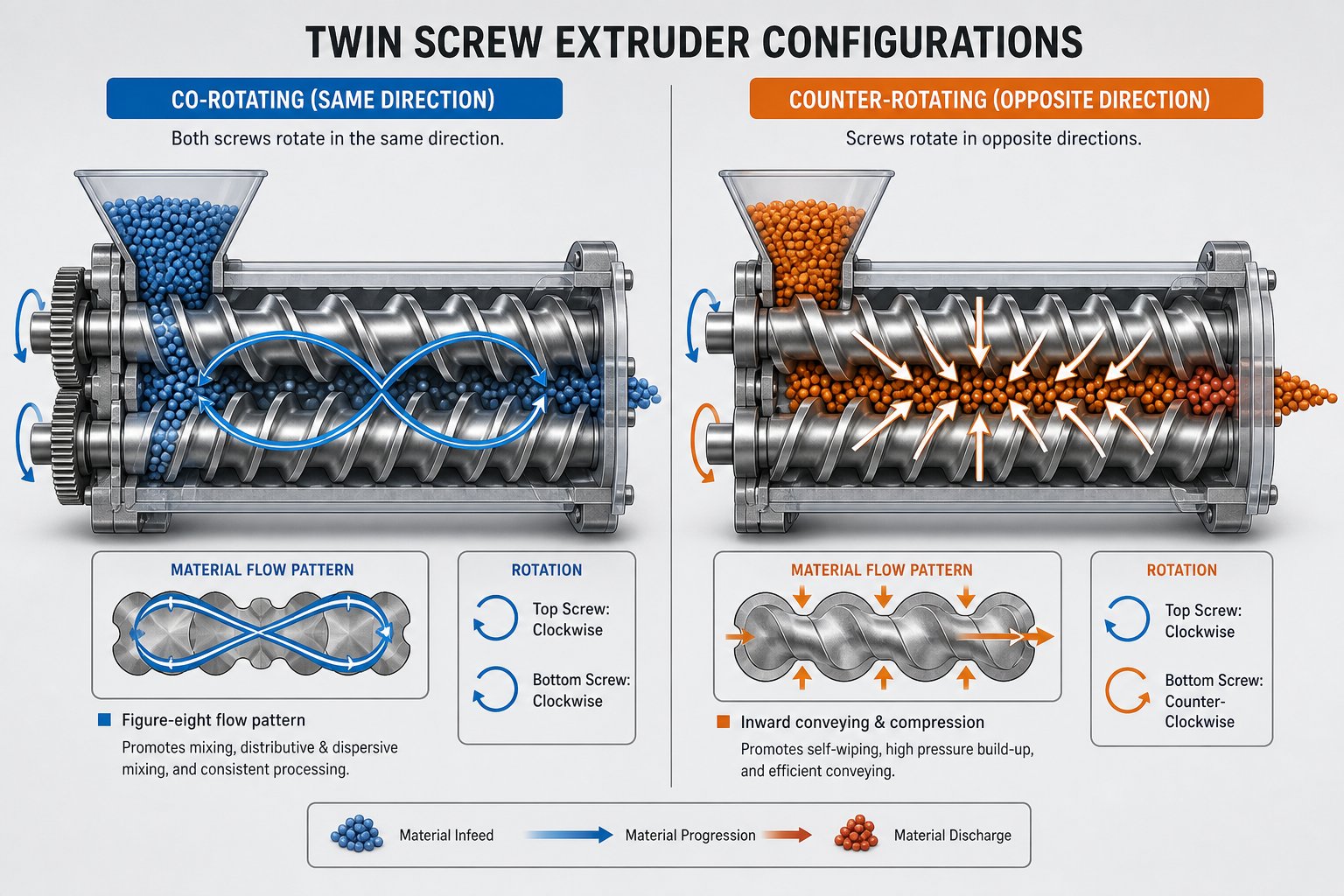
The co-rotating twin screw extruder is the dominant workhorse in laboratory research — and for good reason. In this design, both screws turn in the same direction with a fully intermeshing geometry. Picture two helical screws meshing together like gears: material is forcibly transferred from one screw flight to the next at the intermeshing zone, creating an intense, figure-eight flow path that stretches and folds the melt repeatedly.
This geometry produces a self-wiping action that is critical in a research context. As Technovel's extrusion specialists explain, the self-wiping behavior suppresses stagnation and adhesion, keeping the residence time distribution narrow — a particularly important factor during reactive extrusion and the processing of thermally sensitive materials. For researchers, narrow residence time distribution means more consistent data from run to run, fewer degradation artifacts, and cleaner transitions between experimental conditions.
What makes this configuration so versatile in the lab? Several characteristics converge:
- Excellent distributive and dispersive mixing. Intense shear fields develop between the screws and between screw and barrel, while kneading block elements introduce elongational flow components. Together, these impose a complex deformation history on the material — ideal for breaking up filler agglomerates, refining phase morphology in polymer blends, or promoting mass transfer in reactive systems.
- Modular screw element design. Conveying elements, kneading blocks, and mixing elements can be assembled in virtually any sequence on splined shafts. This freedom lets a researcher reconfigure the screw profile in under an hour to target an entirely different material or process challenge.
- Broad application range. From compounding nanocomposites and masterbatches to reactive extrusion and devolatilization, the co-rotating parallel twin screw extruder handles them all without requiring a different machine.
The practical result? A single co-rotating lab extruder can serve multiple research programs simultaneously — polymer blending studies in the morning, filler dispersion trials in the afternoon — simply by swapping screw elements and adjusting process parameters.
Counter-Rotating Configuration and Specialized Uses
Counter-rotating designs take a fundamentally different approach. Here, the two screws rotate in opposite directions. At the intermeshing zone, material is drawn inward and compressed rather than handed off in a figure-eight pattern. This creates closed, C-shaped chambers that transport material forward through positive displacement — similar in principle to a gear pump.
The shear environment is markedly gentler. As Cowell Extrusion notes, counter-rotating designs generate low shear stress and low frictional heat, effectively preventing local overheating. Materials that degrade rapidly under high shear — rigid PVC being the classic example — can be processed stably in a counter-rotating double screw extruder where a co-rotating machine would cause yellowing or decomposition.
Counter-rotating systems come in two sub-categories worth distinguishing:
- Intermeshing counter-rotating. These provide strong positive conveying and precise pressure buildup. A conical twin screw extruder — where screw diameter tapers from the feed end to the discharge — is a common variant in this category, combining the counter-rotating advantages with a natural compression zone. These machines excel in PVC formulation research and profile extrusion studies.
- Non-intermeshing counter-rotating. The screws operate more independently, producing even lower shear. These are less common in laboratory settings but find niche use in gentle blending or processing of extremely shear-sensitive materials.
When would a lab researcher deliberately choose a counter-rotating configuration? The answer almost always ties back to material sensitivity. If you're developing PVC pipe or profile formulations, studying calender feeding behavior, or working with thermally unstable biopolymers where even moderate shear causes degradation, the counter-rotating platform becomes essential. Its calendering effect — the compressive and elongational deformation at the intermeshing region — provides effective dispersive mixing of additives without the aggressive shear that would damage the matrix material.
Choosing the Right Configuration for Your Research
The decision between co-rotating and counter-rotating isn't about which is "better" — it's about which matches your research objectives and material constraints. The table below lays out the comparison across the parameters that matter most in a laboratory context:
| Performance Criterion | Co-Rotating Intermeshing | Counter-Rotating Intermeshing |
|---|---|---|
| Mixing Intensity | High — strong distributive and dispersive mixing | Moderate — relies on compressive and elongational deformation |
| Shear Levels | High shear, adjustable via screw element selection | Low shear, inherently gentle processing |
| Self-Wiping Capability | Excellent — minimal dead zones, narrow residence time distribution | Limited — C-shaped chambers transport material but do not fully self-wipe |
| Typical Lab Applications | Compounding, reactive extrusion, devolatilization, nanocomposites, polymer blends | PVC formulation, profile extrusion studies, calender feeding, heat-sensitive materials |
| Throughput Flexibility | Wide range — degree of fill easily controlled via starve feeding | Narrower range — typically operates at high fill levels |
| Modular Element Availability | Extensive — wide variety of conveying, kneading, and mixing elements available | More limited — fewer element types, less screw design freedom |
For the majority of laboratory compounding and formulation research, co-rotating intermeshing extruders offer the greatest flexibility and data transferability to production-scale equipment.
This doesn't diminish the counter-rotating platform's value — it simply reflects the reality that most lab programs span multiple materials and research objectives over time. A co-rotating machine adapts to that breadth. Researchers focused exclusively on PVC or other heat-sensitive material families, however, will find the counter-rotating configuration not just preferable but necessary for generating meaningful results.
Whichever configuration sits on your lab bench, the next layer of decision-making drills into the technical specifications that define what that machine can actually do — screw diameter, L/D ratio, torque capacity, and the modularity that transforms a fixed piece of hardware into a flexible research instrument.
Essential Technical Specifications for Lab-Scale Twin Screw Extruders
A screw configuration tells you how your machine processes material. Technical specifications tell you what it can handle — and where its limits lie. Misreading a spec sheet, or overlooking a single parameter, can mean purchasing a twin screw extruder machine that chokes on your high-viscosity compound or lacks the processing length for proper devolatilization. Here's a breakdown of the numbers that actually matter.
Screw Diameter and L/D Ratio Explained
Screw diameter is the most fundamental sizing parameter on any screw extruder. In the lab, diameters commonly range from 12 mm to 30 mm. A 12 mm machine might consume only 100 to 200 grams of material per hour — perfect for expensive pharmaceutical APIs or novel nanomaterials. A 27 mm unit pushes several kilograms per hour, offering enough volume for downstream characterization like tensile testing or film extrusion trials.
Equally important is the L/D ratio — the total length of the processing section divided by the screw diameter. Lab extruders typically offer L/D ratios from 25:1 to 40:1, with some modular platforms reaching 48:1 or even 60:1 through the addition of extra barrel segments. Why does a longer L/D matter? Each additional unit of length adds another processing zone — more room for sequential operations like melting, distributive mixing, venting, side feeding, and pressure buildup before the die. A 25:1 ratio might be adequate for straightforward melt blending, but reactive extrusion or multi-stage devolatilization often demands 40:1 or more to accommodate all the required unit operations along a single screw path.
Torque, Speed, and Throughput Specifications
Think of torque as the engine strength of your extruder. Specific torque — torque density per unit of screw volume — determines whether the machine can process high-viscosity engineering thermoplastics or heavily filled compounds without tripping its safety clutch. A machine with high specific torque handles demanding materials at lower speeds, preserving thermal stability. When evaluating a twin screw barrel system, always check the maximum allowable torque per shaft, not just the motor rating.
Screw speed is the other half of the energy equation. Co-rotating lab extruders frequently offer speeds up to 1,200 rpm or higher. Higher rpm increases shear rate and reduces residence time simultaneously — a trade-off researchers must manage carefully. Doubling the screw speed does not simply double the output; it also alters the melt temperature, the degree of fill, and the mixing intensity. As a practical starting point, specific throughput (output in kg/hr divided by rpm) helps maintain comparable processing conditions when scaling a recipe to different rates on the same machine.
Throughput itself scales roughly with screw diameter. A 16 mm screw extruder might top out at 2 to 5 kg/h, while a 27 mm platform can reach 10 kg/h or beyond. Matching throughput capability to your experimental needs prevents both material waste on oversized machines and bottleneck frustrations on undersized ones.
Barrel and Screw Element Modularity
Modularity is what transforms a twin screw and barrel assembly from a fixed processing tool into a flexible research instrument. Modern lab extruders use segmented screw elements — conveying flights, kneading blocks of varying stagger angles, distributive mixing elements, and toothed blending elements — that slide onto splined shafts in any order. Changing a screw profile can take as little as 20 minutes, enabling researchers to test aggressive mixing one run and gentle blending the next without purchasing a separate machine.
Barrel modularity follows the same logic. Individual barrel segments can be configured with open ports for side feeders, atmospheric vents, vacuum vents, or liquid injection nozzles. Removing or adding a barrel section adjusts the L/D ratio and reshapes the processing sequence entirely. This segmented approach, where screw and barrel geometries are matched to the process, is what makes lab-scale twin screw extrusion so adaptable across diverse research programs.
Before committing to any platform, make sure you evaluate the following specifications — they define the boundaries of every experiment you'll run:
- Screw diameter — determines throughput range and material volume requirements per trial
- L/D ratio — governs the number of available processing zones for sequential unit operations
- Specific torque — dictates the ability to process high-viscosity or highly filled materials
- Maximum screw speed — sets the upper limit of shear rate and energy input
- Free volume — the usable volume inside the barrel between screw flights, affecting fill level and throughput capacity
- Number of barrel zones — defines how many independent temperature and functional zones can be configured
Each of these specs interacts with the others. A high L/D ratio is only useful if you have enough barrel zones to control temperature independently across that length. Generous free volume means little if the torque capacity can't handle a filled compound at reasonable speeds. Evaluating these parameters as a system — rather than comparing individual numbers in isolation — is what separates a well-chosen lab platform from an expensive disappointment.
Of course, specifications set the hardware boundaries. What happens inside those boundaries — the barrel temperature profiles, feed strategies, and screw speed settings you select — is where the real science of lab extrusion plays out.
Mastering Barrel Zones and Process Parameters in Lab Extrusion
Specifications define what your extruder can do. Process parameters determine what it actually does to your material. Two researchers running identical formulations on the same twin-screw extruder can produce wildly different results — different dispersion quality, different melt temperatures, different degradation levels — based solely on how they set barrel temperatures, screw speed, and feed rate. Mastering these variables, and understanding how they interact, is what separates productive lab extrusion from expensive trial-and-error.
Barrel Segmentation and Independent Temperature Zone Control
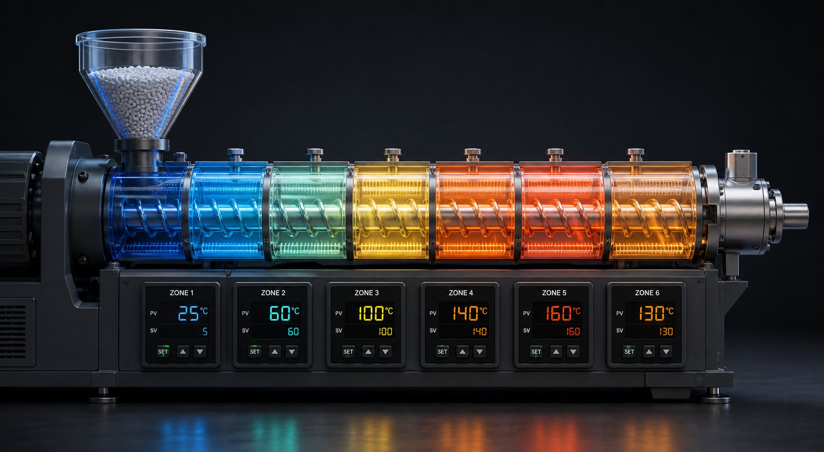
Walk up to any modern lab extruder system and you'll notice the barrel isn't a single heated tube. It's a series of individually controlled segments — typically 6 to 12 independent zones depending on the machine's L/D ratio. Each zone contains its own electric cartridge heaters and liquid cooling channels, governed by dedicated temperature controllers that maintain setpoints within tight tolerances.
Why does this matter so much? Because different stages of the extrusion process demand different thermal conditions. In the feed zone, temperatures often stay low to prevent premature melting that would block incoming material. Moving downstream, temperatures rise through the melting and mixing zones, then may drop again near the die to increase melt viscosity for stable strand formation. This deliberate thermal shaping — a custom temperature profile — is one of the most powerful tools a researcher controls.
Consider how this works in practice. A study on PLA/PBSe blend optimization used an 11-barrel twin-screw extruder with a carefully designed "hump" temperature profile: 150/175/180/185/190/190/185/180/175/170/170 degrees Celsius. The logic behind this profile is instructive. Lower initial temperatures prevented solid material from compacting and blocking the feed section. The gradual rise ensured complete PLA melting. The peak in the middle zones lowered viscosity to improve mixing efficiency. And the reduction toward the die increased melt strength for clean pelletizing. Every degree in every zone served a specific engineering purpose.
Modern barrel extruder temperature control relies on PID (Proportional-Integral-Derivative) algorithms that continuously adjust heater output and cooling flow to minimize overshoot and stabilize temperatures at setpoints. More advanced PLC-based systems can employ dual thermocouples — one in the barrel wall, another at the heater — to calculate corrections faster and reduce the temperature fluctuations that plague simpler single-thermocouple setups. For research applications where even a few degrees of variation can alter crystallization behavior or trigger degradation, this precision is not a luxury. It's a requirement.
This granular, zone-by-zone thermal control is one of the primary advantages of lab-scale work over batch mixing. A Brabender or internal mixer gives you one temperature setpoint for the entire chamber. A segmented lab extruder gives you a dozen independent thermal levers, each influencing a distinct processing stage. That difference translates directly into richer, more actionable experimental data.
Critical Process Parameters and Their Effects
Temperature profiles are just one dimension of the control landscape. Researchers working with a twin-screw extruder must simultaneously manage several interdependent parameters, each producing distinct — and sometimes competing — effects on the final product. The table below maps the key inputs to their primary processing outcomes:
| Process Parameter | Primary Effects on Processing |
|---|---|
| Screw Speed (rpm) | Controls shear rate, influences melt temperature through viscous dissipation, affects degree of fill and residence time. Higher speeds increase dispersive mixing intensity but reduce the time material spends in each zone. |
| Barrel Temperature Profile | Governs melting onset, melt viscosity, crystallization behavior, and thermal degradation risk. Directly shapes the thermal history of the material from feed to die. |
| Feed Rate (kg/h) | Determines degree of barrel fill, residence time, and specific mechanical energy (SME) input. Lower feed rates at constant screw speed mean longer residence and more mixing per unit mass. |
| Screw Configuration | Defines the location and intensity of mixing, melting, and pressure generation zones. Kneading block geometry (width, stagger angle, forward vs. reverse pitch) directly controls dispersive vs. distributive mixing balance. |
| Vacuum Level (at vent ports) | Drives devolatilization efficiency — removal of moisture, unreacted monomers, solvents, or trapped air. Higher vacuum pulls more volatiles but requires careful screw design upstream to prevent vent flooding. |
Each of these parameters generates measurable effects that researchers track: melt temperature at the die, torque as a percentage of motor capacity, specific mechanical energy input, and product quality metrics like particle dispersion or volatile residual levels. In a well-instrumented extruder system, all of these signals are logged continuously, building the dataset that supports formulation decisions and future scale-up.
A practical example illustrates the power of systematic parameter control. The PLA/PBSe blend study referenced earlier ran a 121-simulation Design of Experiment, varying screw speed from 150 to 300 rpm and feed rate from 8 to 14 kg/h across 11 steps each. The outputs they tracked — global mixing index, specific mechanical energy, torque, maximum material temperature, residence time, and exit viscosity — revealed that low screw speed combined with high throughput simultaneously maximized mixing efficiency, reduced energy consumption, and prevented thermal degradation. That kind of multivariate insight is simply impossible to obtain without the independent parameter control that a lab-scale twin-screw extruder provides.
Interactions Between Parameters
Here's where lab extrusion gets genuinely complex — and genuinely powerful. These parameters don't operate in isolation. They interact, sometimes synergistically, sometimes antagonistically. Increase screw speed and you raise shear rate, which improves dispersive mixing. But that same speed increase reduces residence time, which can hurt distributive mixing and devolatilization efficiency. Simultaneously, higher shear generates viscous dissipation heat, pushing melt temperature upward even if your barrel setpoints remain constant.
Lower the feed rate to extend residence time under a vacuum vent? You'll improve volatile removal, but you'll also increase the specific energy input per kilogram of material, potentially causing thermal degradation in heat-sensitive polymers. Adjust a kneading block to a more aggressive reverse-pitch configuration? Mixing intensity jumps, but so does local pressure, and a bypass valve extrusion setup or pressure relief strategy may become necessary to prevent excessive backpressure at the die.
These interdependencies are precisely why design-of-experiment (DOE) approaches have become standard practice in lab extrusion research. Rather than changing one parameter at a time — the classic "trial-and-error" approach that wastes material and misses interaction effects — a DOE framework varies multiple inputs simultaneously, mapping their combined effects on output quality. The controllability of lab machines makes them ideal platforms for this kind of systematic study. You can hold screw configuration constant while sweeping temperature and speed, then change one screw element and repeat the sweep. Each run consumes minimal material, and the resulting response surfaces reveal optimization pathways that single-variable experiments would never uncover.
The Ludovic simulation-assisted DOE approach used in the PLA/PBSe research exemplifies this methodology. By modeling screw geometry, material rheology, and thermal properties before running physical experiments, the researchers identified optimal processing windows computationally — then validated them on the actual extruder. This simulation-to-experiment workflow reduces material consumption further, accelerates development timelines, and builds process understanding that is directly transferable to larger equipment.
Mastering these parameter interactions isn't just an academic exercise. It determines whether the formulations you develop in the lab will behave predictably when they encounter real-world conditions — different throughputs, different shear histories, different thermal environments. And those real-world conditions extend well beyond traditional polymer compounding. The range of applications where lab-scale twin screw extrusion is now indispensable keeps expanding into territory that would have seemed improbable a decade ago.
Key Applications From Polymer Research to Pharma and Beyond
Parameter mastery and screw configuration expertise are only as valuable as the research problems they solve. And those problems have multiplied dramatically. What started as a polymer compounding tool has evolved into a platform technology spanning industries that rarely share conference halls — from pharmaceutical formulation labs to battery electrode research cells. Here's where the twin screw extruder laboratory is delivering results that matter, and where the frontier is heading next.
Polymer Compounding and Materials Development
This remains the heartland application. A compounding twin screw extruder at lab scale lets researchers blend polymers with fillers, stabilizers, pigments, and reinforcing agents — iterating through dozens of formulations in a single day while consuming only a few kilograms of material total. Imagine testing 15 different carbon nanotube loadings in a polycarbonate matrix before lunch. On a production-scale machine, that exercise would burn through hundreds of kilograms of resin and days of machine time. On a lab extruder for polymer research, it takes hours and grams.
The breadth of materials development work running through these machines is striking. Nanocomposite research relies on lab extruders to achieve uniform dispersion of graphene, nanoclay, or silica nanoparticles — a challenge where screw configuration and processing conditions directly determine whether filler agglomerates break apart or survive intact. Color concentrate and masterbatch development uses the same platform to fine-tune pigment loading and carrier compatibility. Filled systems — glass fiber, mineral filler, carbon fiber composites — demand high torque and carefully sequenced screw profiles that only a modular twin screw compounding extruder can deliver at research scale.
One area gaining rapid momentum is recycled and sustainable polymer development. Researchers compounding post-consumer recycled plastics face highly variable feedstocks — fluctuating melt flow indices, contamination, mixed polymer fractions. A plastic twin screw extruder in the lab provides the controlled environment needed to evaluate compatibilizers, chain extenders, and stabilizer packages that can restore recycled materials to useful performance levels. The same machines process biopolymer blends — PLA with PBAT, starch-based formulations, cellulose fiber-reinforced biocomposites — where thermal sensitivity demands the precise temperature and shear control that lab-scale equipment excels at.
Pharmaceutical Hot-Melt Extrusion
If polymer compounding is the twin screw extruder's birthplace, pharmaceutical R&D has become its most demanding proving ground. Hot-melt extrusion (HME) is now widely established as the preferred technique for creating amorphous solid dispersions (ASDs) — molecular-level mixtures of a poorly soluble drug within a polymer carrier that dramatically improve bioavailability.
Why does this matter? Roughly 40% or more of drug candidates in pharmaceutical development pipelines suffer from poor aqueous solubility. Without an enabling formulation strategy, these compounds fail to reach therapeutic concentrations in patients. ASDs produced by HME convert the crystalline drug into an amorphous state and stabilize it within a polymeric matrix — PVP VA64, HPMCAS, and Soluplus are among the common carriers — unlocking dissolution and absorption improvements that can reach fourfold or greater compared to crystalline tablet formulations.
A compelling illustration comes from Boehringer Ingelheim's published work on developing an ASD for an insoluble compound. Their team used a 9 mm co-rotating twin screw mini-extruder to screen polymer-drug combinations at batch sizes of just 5 to 20 grams — systematically identifying PVP VA64 as the optimal carrier through solubility parameter calculations, hot-stage microscopy, and thermal analysis. The PVP VA64-based ASD ultimately delivered 80.6% relative bioavailability compared to an oral solution in dog studies — a fourfold improvement over the crystalline tablet. Critically, the entire formulation development consumed approximately 500 grams of API, and the team progressed from lab-scale feasibility to clinical batch manufacture within seven months.
This example highlights why lab-scale twin screw extrusion has become indispensable in pharma. Small batch sizes conserve expensive APIs during early development. Continuous processing — even at gram-per-minute feed rates — generates process-relevant data (specific energy, residence time, melt temperature) that transfers directly to scale-up. And the modular screw and barrel architecture enables rapid cleaning and reconfiguration between compounds, which is essential in GMP-regulated environments where cross-contamination is unacceptable.
Regulatory trends are amplifying this momentum. The FDA's encouragement of continuous manufacturing over traditional batch processing positions twin screw extrusion as a natural fit. A polymer extruder running continuously in a pharmaceutical lab isn't just a research tool — it's a prototype of the production process itself, generating the data regulators expect to see in filings.
Emerging and Cutting-Edge Applications
Beyond established polymer and pharma domains, laboratory twin screw extruders are penetrating fields where their capabilities solve problems that conventional batch equipment cannot. Several frontier applications deserve attention:
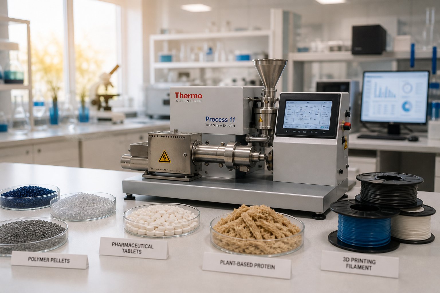
- Battery electrode processing and dry electrode research. Twin-screw extruders are being deployed for continuous cathode and anode slurry mixing, replacing batch planetary mixers that require four to eight hours per batch. The extruder's higher shear forces produce narrower particle size distributions, while continuous operation eliminates batch-to-batch variation. Perhaps more significant is dry electrode research — using a polymeric binder that fibrillates under shear to bind cathode active materials without any solvent, a twin-screw compounding process that could eliminate the energy-intensive drying step entirely. Lab-scale extruders with 11 mm to 16 mm screws enable researchers to explore these novel electrode architectures with as little as 100 grams of cathode material.
- 3D printing filament development. Custom polymer formulations for fused filament fabrication require precise melt blending, consistent diameter control, and the ability to incorporate functional additives — conductive fillers, flame retardants, color pigments — into a uniform filament. A polyester extruder or other lab-scale compounding extruder paired with a filament die and diameter measurement system lets researchers prototype specialty filaments without outsourcing to a compounder.
- Food extrusion R&D for plant-based proteins. The texturization of soy, pea, and other plant proteins into fibrous, meat-like structures relies on twin screw extrusion under high moisture conditions. Lab-scale machines allow food scientists to screen protein blends, binding agents, and flavor systems while controlling the thermomechanical history that determines fiber formation and mouthfeel.
- Reactive extrusion for chemical modification of biopolymers. Grafting, crosslinking, and compatibilization reactions can be conducted inside the extruder barrel during processing — no separate reactor needed. Lab-scale reactive extrusion enables controlled modification of starch, cellulose, chitosan, and lignin-based materials, producing functionalized biopolymers for packaging, biomedical, and agricultural film applications.
- Solid-state battery and solid electrolyte development. As Thermo Fisher's process specialists note, sulfide solid electrolytes and pure lithium anode materials require processing under inert argon atmospheres. Lab-scale twin screw extruders compact enough to operate inside glove boxes are enabling this next-generation battery research at volumes that match limited material availability.
What unites these diverse applications is a common thread: continuous, controllable thermomechanical processing at volumes small enough for research yet representative enough for scale-up. The compounding extruder that processes a polymer blend at 500 grams per hour uses the same fundamental principles as the one producing pharmaceutical dispersions or electrode slurries — modular screw design, independent thermal zones, and precise parameter control.
Still, even the most capable machine produces disappointing results when common operational problems go undiagnosed. Output surging, die drool, degradation artifacts — these practical realities of daily lab extrusion receive almost no coverage, yet they derail experiments as reliably as any equipment limitation.
Troubleshooting, Safety, and Cleanability in Twin Screw Extruders
You've optimized your screw configuration, dialed in temperature profiles, and designed a rigorous DOE. Then the extrudate starts pulsing. Or a faint brown discoloration appears in what should be a clear melt. Or the vent port begins spitting material instead of pulling vacuum. These are the moments that separate productive lab days from frustrating ones — and they happen to every researcher, regardless of experience level. The practical knowledge for diagnosing and resolving common twin screw extruder problems rarely appears in textbooks or equipment manuals. Here's what you actually need to know.
Common Laboratory Extrusion Problems and Diagnosis
Most issues researchers encounter with twin screw extruders fall into a handful of recurring categories. The tricky part isn't recognizing the symptom — it's tracing it back to the right root cause, because a single symptom can originate from multiple sources. Output surging, for example, might look like a feeding problem at first glance, but it could just as easily stem from an incorrect barrel temperature in the solids conveying zone or a screw element sequence that creates inconsistent pressure at the die.
Consider output surging — that rhythmic fluctuation in throughput that shows up as variable strand diameter or inconsistent pellet size. In single-screw systems, improper temperatures in the solids conveying section are the most common culprit: a feed casing that runs too hot or insufficient screw cooling disrupts the balance between forwarding and retarding forces on the solid polymer plug. In twin-screw extruders operating under starve-fed conditions, surging more often points to feeder inconsistencies — loss-in-weight feeder calibration drift, bridging in the hopper, or feed throat blockages caused by premature softening of low-melt-point materials. The diagnostic approach starts at the feeder and works downstream.
Die drool is another persistent headache. That slow accumulation of degraded material around the die lip eventually breaks free and contaminates the extrudate. Root causes typically involve excessive melt temperature at the die, incompatible additives migrating to the surface, or insufficient land length in the die geometry. Vent flooding — where molten material backs up through vacuum ports instead of allowing volatiles to escape — usually indicates that the screw elements upstream of the vent port are generating too much pressure, or that the degree of fill in the venting zone is too high relative to the melt viscosity.
The following table maps the most frequent problems to their likely causes and practical corrective actions:
| Problem | Likely Causes | Corrective Actions |
|---|---|---|
| Output surging (fluctuating throughput) | Feeder calibration drift; hopper bridging; premature melting in feed zone; inconsistent screw pressure buildup | Recalibrate gravimetric feeder; lower feed zone temperature; check for material buildup in feed throat; verify screw element sequence near die |
| Die drool and die buildup | Excessive melt temperature; additive bloom or migration; inadequate die land length; low-molecular-weight fraction accumulation | Reduce final barrel zone and die temperatures; evaluate additive compatibility; clean die face regularly; consider die geometry adjustment |
| Material degradation (discoloration, odor, reduced properties) | Barrel temperatures too high; excessive residence time; aggressive kneading elements generating viscous dissipation heat; insufficient nitrogen blanketing for oxygen-sensitive materials | Reduce barrel setpoints in high-shear zones; increase feed rate to reduce residence time; replace aggressive kneading blocks with wider-pitch mixing elements; add nitrogen purge at feed throat |
| Inconsistent filler dispersion | Insufficient mixing intensity; filler feeding downstream of mixing zone; filler agglomerates too hard for available shear; improper side feeder split ratio | Add or reconfigure kneading blocks; reposition side feeder upstream of primary mixing zone; increase screw speed selectively; evaluate filler surface treatment |
| Vent flooding during devolatilization | Excessive degree of fill at vent zone; insufficient pressure seal upstream of vent; melt viscosity too low to maintain melt ring; screw configuration lacking reverse elements before vent | Reduce feed rate; add left-handed conveying elements before vent to create melt seal; increase melt viscosity by lowering vent zone temperature; check vacuum trap for blockage |
A practical diagnostic habit that saves hours of guesswork: monitor torque and die pressure trends continuously. Stable torque with fluctuating die pressure usually points to issues downstream of the melting zone — die blockage, screen pack clogging, or inconsistent melt homogeneity. Fluctuating torque with stable die pressure suggests the problem originates in the feed or melting sections. Trending both signals together on a data acquisition system turns vague symptoms into actionable diagnoses.
Safety Considerations for Lab-Scale Extrusion
Lab-scale screw extruders are physically smaller than their production counterparts, but they operate at the same temperatures and pressures — and they do so in confined spaces where researchers work in close proximity. That combination creates safety risks that are easy to underestimate. A 16 mm extruder running at 280 degrees Celsius is just as capable of causing severe burns as a 90 mm production machine; the barrel surface is simply closer to your hands.
High-temperature surface exposure is the most immediate hazard. Barrel segments, die adapters, and strand pelletizer components all reach temperatures well above the boiling point of water. In production plants, these surfaces are typically shielded behind safety enclosures. In laboratories, researchers frequently work around exposed barrels during setup, sampling, and screw changes. Heat-resistant gloves, barrel insulation jackets, and disciplined awareness of hot surfaces are non-negotiable.
Fume extraction demands careful planning, especially for reactive extrusion and pharmaceutical applications. Processing certain polymers — PVC, fluoropolymers, or materials containing volatile plasticizers — releases gases that pose inhalation risks. Reactive extrusion involving peroxide-initiated crosslinking or grafting can generate volatile byproducts. Laboratory ventilation specialists emphasize the importance of completing a thorough risk assessment for airborne exposure, ensuring adequate exhaust capacity (measured in CFM), and supplying tempered makeup air to replace what the extraction system removes. Positioning the extruder under or adjacent to a fume hood — or installing a dedicated local exhaust system at the die and vent ports — keeps volatile concentrations below permissible limits.
Lockout/tagout (LOTO) procedures apply to lab-scale twin-screw extruders just as rigorously as to industrial equipment. Before any screw removal, barrel disassembly, or maintenance task, the motor must be electrically isolated, heaters de-energized, and the machine verified as safe. The compact size of lab equipment can foster a false sense of informality — but a co-rotating screw pair spinning at 600 rpm generates enough torque to cause serious injury if the drive engages unexpectedly during a screw change.
Pressure relief at the die is another safety element that deserves attention. If a die becomes blocked — by solidified material, a screen pack failure, or a crosslinked gel — pressure can build rapidly inside the barrel. Production machines incorporate rupture disks or relief valves. Lab machines should have equivalent protection, whether through a mechanical pressure relief device or an automated shutdown triggered by a die pressure sensor exceeding a preset limit.
Cleaning and Contamination Prevention
In a production environment, running a few kilograms of purge compound between material changes is standard practice. In a laboratory, the stakes are higher. Pharmaceutical researchers studying drug-polymer dispersions cannot tolerate even trace contamination from the previous experiment's API. Food extrusion scientists processing allergen-containing formulations must achieve verified cleanliness before switching products. Cross-contamination doesn't just compromise data — in regulated environments, it can invalidate entire experimental campaigns.
Purging is the first line of defense. The process follows a logical sequence: run the barrel temperatures up to the recommended purge range, stop feeding the production material, and introduce a purging compound that displaces residual polymer, loosens carbon buildup, and pushes contamination out through the die. Mechanical purging compounds — which form a dense thermoelastic plug that physically scrubs barrel and screw surfaces — tend to be particularly effective in screw plastic extruder systems where chemical purge residues are undesirable. You continue purging until the extrudate runs clear, then transition directly to the next material or shut down for disassembly.
For applications requiring absolute cleanliness, purging alone isn't sufficient. Complete barrel disassembly and screw removal allow visual inspection and manual cleaning of every surface. This is where modular design pays dividends far beyond experimental flexibility. A segmented barrel system lets you unbolt individual sections, inspect bore surfaces for deposits, and clean each piece independently. Similarly, screw elements that slide off splined shafts can be individually inspected, ultrasonically cleaned, or replaced if worn.
Quick-change screw and barrel features — increasingly standard on modern laboratory twin-screw extruders — reduce the downtime penalty of thorough cleaning. Some platforms allow full screw extraction in under 10 minutes without disconnecting barrel heating or cooling lines. Others offer split-barrel designs that hinge open to expose both screws and barrel bore simultaneously. These features transform what would be a half-day maintenance chore on a bolted-flange production machine into a manageable between-experiments procedure.
A few practical habits make cleaning more effective and less time-consuming:
- Purge before shutdown, not after startup. Cleaning a hot, recently-run machine is far easier than trying to remove cold, solidified residue the next morning.
- Inspect screw elements after every disassembly. Worn or damaged kneading block tips create dead zones that trap material and become chronic contamination sources.
- Document cleaning procedures and verify results. In GMP-regulated pharma or food labs, cleaning validation — often using swab sampling and analytical testing — must demonstrate that residual contamination falls below defined acceptance limits.
- Maintain dedicated screw sets for incompatible material families. Running silicone-containing formulations through the same screw elements used for adhesion-critical materials is a recipe for delamination failures that surface weeks later and are maddeningly difficult to trace.
Troubleshooting, safety, and cleaning discipline aren't glamorous topics — but they're the operational foundation that determines whether your lab produces reliable, publishable data or generates noise. With that foundation in place, the strategic question shifts from daily operations to long-term investment: how do you select the right lab extruder in the first place, and what criteria separate a platform that serves your research for years from one that limits it within months?
How to Select the Right Laboratory Twin Screw Extruder
Browsing a twin screw extruder for sale listing — whether from a global OEM catalog or a regional distributor's website — can feel overwhelming. Specifications blur together, every twin-screw extruder manufacturer claims best-in-class performance, and the price tags span an order of magnitude without obvious justification. The real problem isn't a lack of options. It's the absence of a structured decision framework that connects your research needs to the right piece of hardware. Here's how to build one.
Defining Your Research Requirements
Before evaluating a single spec sheet, answer four foundational questions. They sound simple, but skipping any one of them leads to purchasing decisions that look rational on paper and frustrating in practice.
What materials will you process? Thermoplastics, thermoset precursors, pharmaceutical APIs dispersed in polymer carriers, food-grade proteins — each imposes different demands on barrel metallurgy, temperature range, torque capacity, and cleanability. A lab that processes both glass-fiber-reinforced nylon and pharmaceutical-grade PVP needs corrosion-resistant barrels and high wear resistance — a combination that narrows the field quickly.
What throughput and batch size do you need? If your research consumes 200-gram batches of a scarce nanocomposite filler, a 27 mm machine wastes material during startup and purge cycles. A 12 mm or 16 mm platform is a better match. Conversely, if you need enough extrudate for injection molding test bars and mechanical property characterization, you'll want throughput measured in kilograms per hour, not grams.
Which unit operations are required? Simple melt blending needs fewer barrel zones and a less complex screw profile than a process combining reactive extrusion, side feeding of fillers, atmospheric venting, and vacuum devolatilization. Each additional unit operation demands barrel ports, screw element variety, and often a longer L/D ratio.
Is scale-up to production a goal? If your lab data must translate to a production twin-screw extruder machine, you need a lab platform with industry-standard screw element geometry — not a proprietary design that exists only at one diameter. Geometric similarity between lab and production screws is the foundation of reliable scale-up, and it starts with equipment selection.
Evaluating Equipment Features and Total Cost of Ownership
Twin screw extruder price is the number everyone looks at first — and the number that tells you the least. A machine listed at $15,000 that requires $5,000 in annual spare parts, lacks data acquisition software, and offers only three kneading block options may cost more over five years than a $25,000 platform with comprehensive element libraries, integrated sensors, and robust construction that reduces wear-related downtime.
Evaluate candidates against the following criteria, roughly ordered by their impact on long-term research productivity:
- Screw element availability and variety. Can you obtain conveying elements, kneading blocks at multiple stagger angles (30, 45, 60, 90 degrees), distributive mixing elements, and reverse-pitch elements? A limited element library constrains every experiment you'll ever run.
- Barrel modularity and port configuration. How many barrel zones are available? Can you add side feeders, liquid injection ports, and vacuum vents at multiple positions? Modularity determines whether the machine grows with your research or becomes a bottleneck.
- Maximum temperature, torque, and speed. These define the processing envelope. Ensure the machine handles your most demanding material — not just your most common one.
- Data acquisition and software integration. Real-time logging of torque, melt pressure, barrel temperatures, and screw speed is essential for DOE-based research and scale-up documentation. Machines without integrated data capture force manual recording, introducing errors and slowing analysis.
- Installation requirements. Lab extruders need electrical supply (often three-phase), cooling water or chilled water lines, and exhaust ventilation. Verify that your facility can accommodate these before committing to a purchase.
- Spare parts costs and lead times. Replacement screw elements, barrel liners, and wear components represent recurring expenses. Twin screw extruder manufacturers who stock common parts and offer short lead times keep your machine running; those with 12-week backorders on kneading blocks derail research timelines.
- Operator training and technical support. A lab twin screw extruder is only as productive as the person running it. Evaluate whether the supplier offers hands-on training, application support, and responsive troubleshooting assistance.
Total cost of ownership over a realistic five- to seven-year horizon — purchase price plus installation, maintenance, spare parts, training, and downtime costs — provides a far more accurate picture than the initial quote alone. Industry maintenance data suggests that maintenance expenses typically account for 15 to 25 percent of annual operating costs on compounding extruders, and poorly maintained equipment can drive that figure three times higher. Factoring these ongoing costs into your decision prevents the common trap of choosing the cheapest machine upfront only to overspend on replacements and repairs for years afterward.
The Role of Custom Screw Design in Specialized Research
Here's a reality that standard equipment catalogs rarely acknowledge: off-the-shelf screw configurations are designed for general-purpose processing. They work well for common materials and straightforward compounding tasks. But researchers working with novel materials — shear-sensitive biopolymers, ultra-high-viscosity reactive systems, nanofiller dispersions requiring precise elongational flow, or experimental battery electrode formulations — frequently discover that standard element combinations don't deliver optimal results.
The geometry of each screw element — its flight depth, tip width, stagger angle, and length — directly determines the shear rate, pressure profile, and residence time distribution the material experiences. As NC State Extension's extrusion research emphasizes, no gold standard exists for screw profile design because every material exhibits unique flow properties influenced by temperature, shear rate, and extruder geometry. Configuring a screw profile is, in their words, "a blend of art and science."
Custom-designed screw elements — engineered to match a specific material's rheology, thermal sensitivity, and mixing requirements — can dramatically improve research outcomes. Wider kneading blocks promote dispersive mixing for breaking filler agglomerates; narrower ones enhance distributive mixing for blending immiscible phases. Toothed mixing elements add low-shear distributive capability without excessive energy input. Reverse-pitch elements create melt seals for vacuum devolatilization. The right combination, tailored to your material system, can be the difference between publishable dispersion data and an inconclusive experiment.
Most university labs and small R&D teams, however, don't maintain in-house screw design capabilities. This is where external design support becomes a practical asset. NANHAIYA's Custom Screw Design Services offer R&D labs, universities, and pilot-line operators access to application-specific screw and barrel engineering without requiring dedicated design staff. Their service covers specialized materials, compact lab twin screw extruder platforms, and experimental extrusion requirements — precisely the scenarios where generic off-the-shelf configurations fall short.
When comparing twin screw extruder manufacturers, the availability of custom screw design support from specialists like NANHAIYA can serve as a meaningful differentiator. A machine with a broad standard element library is a strong starting point, but the ability to source purpose-built elements for unusual materials or unconventional processes extends the useful life and research reach of your equipment far beyond what catalog options alone can provide.
Selecting the right machine and configuring it for your specific materials lays the groundwork. But for many research programs, the ultimate test of that groundwork isn't the lab result itself — it's whether those results hold up when the process moves to a larger extruder running at ten or a hundred times the throughput.
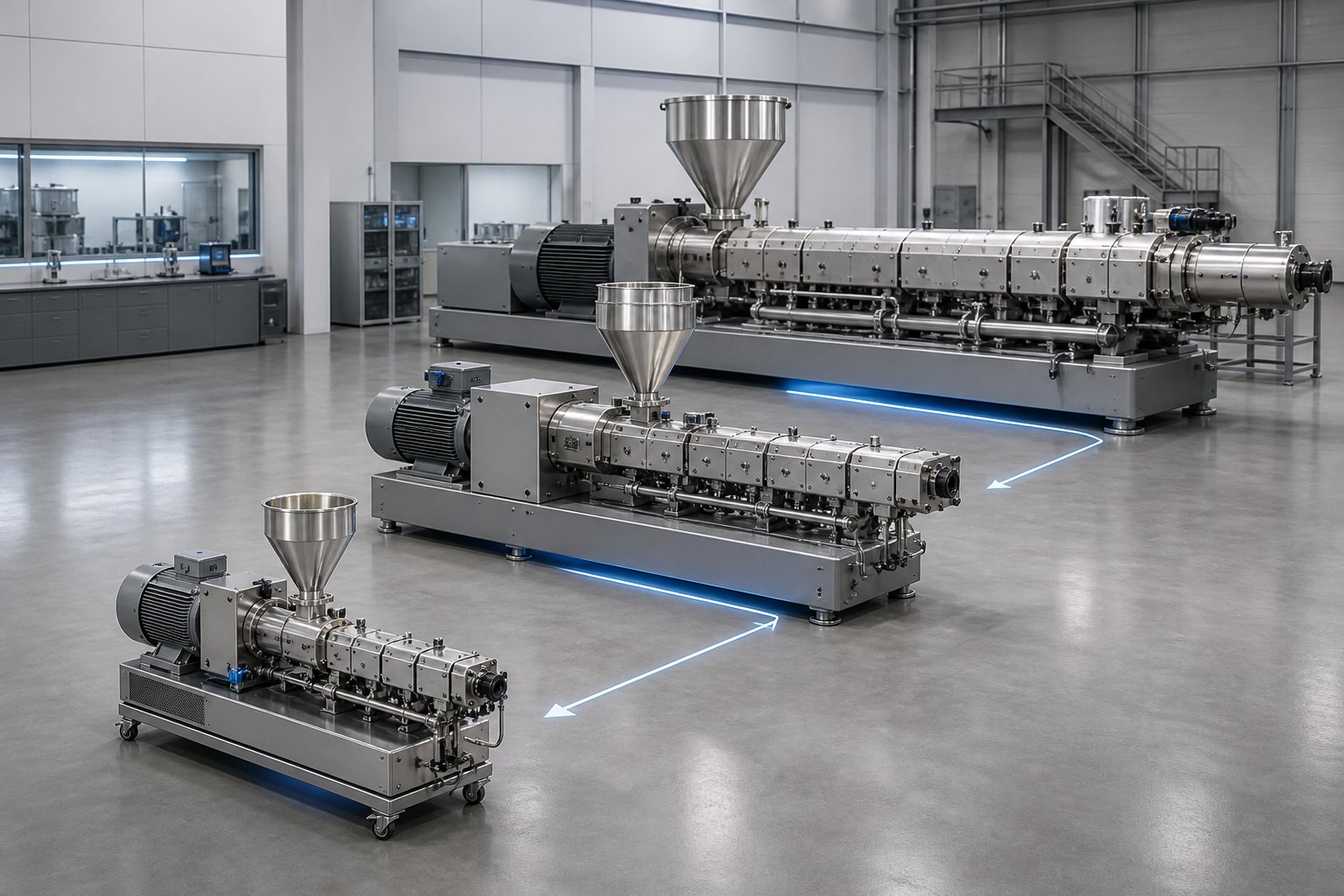
Scaling Up From Lab Twin Screw Extruder to Production
Every formulation optimized on a laboratory extruder eventually faces the same question: will it behave the same way at ten times the throughput? The honest answer — the one that rarely appears in equipment brochures — is "only if you plan for it." Twin screw extrusion scale-up is not a matter of buying a bigger machine and running the same recipe. It is a disciplined translation of material experience from one screw diameter to another, governed by physics that reward preparation and punish assumptions.
Yet despite its importance, scale-up methodology remains the most poorly covered topic in laboratory extrusion literature. Competitor content typically ends with a vague statement about "generating scale-up data" without explaining what that data must include, how geometric relationships between machines dictate parameter transfer, or why a formulation that performs beautifully at 16 mm can fail at 40 mm. Here's the engineering reality behind successful scale-up — and how to set your lab trials up for it from the start.
Principles of Geometric Similarity in Scale-Up
The foundation of reliable twin screw extrusion scale-up is geometric similarity. Two extruders are geometrically similar when every dimension of the smaller machine is multiplied by the same constant to produce the larger one — screw diameter, channel depth, flight width, intermeshing gap, barrel bore — all scaled proportionally. Think of it like a CAD model zoomed in: the shape is identical, only the size changes.
Why does this matter so much? Because geometric similarity preserves the dimensionless flow patterns inside the extruder. When channel depth, flight clearance, and element length all scale with diameter, the shear rate at any given point in the extrudate becomes independent of screw diameter for machines running at the same rpm. The percentage of barrel cross-section occupied by material stays constant. The relative positions of mixing zones, venting sections, and pressure-buildup regions remain unchanged. In short, the material "sees" the same processing environment regardless of machine size.
For laboratory extruders, this has a direct practical implication: the screw element geometry on your lab machine must match the geometry family used on the production platform you intend to scale into. If your 16 mm lab extruder uses a proprietary element design with no counterpart at 40 mm or 60 mm, you lose geometric similarity at the most fundamental level. The screw profile that produced your best results simply cannot be replicated at larger diameter. This is why experienced researchers select laboratory extruders from equipment families that share standardized element geometry across multiple screw diameters — the same conveying pitch ratios, the same kneading block stagger angles, the same flight-to-channel-depth proportions at every scale.
Several assumptions underpin geometric scale-up, and violating them introduces unpredictable behavior:
- L/D ratio must remain consistent. If the lab and production extruders have different L/D ratios, the shorter machine can sometimes be adapted by adding unfilled conveying elements in non-critical zones of the longer screw, but removing functional elements from a longer profile to fit a shorter machine is far more problematic.
- Screw-to-barrel clearances must scale proportionally. Some double screw extruder machine platforms do not maintain proportional gaps across sizes — always verify by measurement.
- Heating and cooling of the barrel should be minimized during scale-up trials. Heat transfer through the barrel wall does not scale geometrically, and heavy reliance on external heating or cooling at lab scale creates conditions that cannot be reproduced on larger equipment.
That last point deserves emphasis. Thermo Fisher's pharmaceutical extrusion team stresses that as screw diameter increases, surface area grows with the square of the diameter while material volume grows with the cube. The ratio of heat-transfer surface to process volume drops with every step up in size. A lab process that depends heavily on barrel heating to reach melt temperature — or on barrel cooling to prevent overheating — may find those thermal crutches unavailable at production scale, where the barrel simply cannot add or remove heat fast enough per kilogram of material. Designing lab processes to approach adiabatic behavior once steady state is reached produces the most scalable results.
Key Scale-Up Parameters and Ratios
Geometric similarity sets the stage, but successful scale-up also demands quantitative alignment of the parameters that define the material's thermomechanical experience inside the extruder.
Volumetric throughput scaling. For geometrically similar extruders running at the same screw speed, throughput scales with the cube of the screw diameter ratio. The math is straightforward: the cross-sectional area of the extrudate channel scales with D squared, and material advances forward one pitch per revolution — a distance proportional to D — so the volume conveyed per revolution scales with D cubed. Moving from a 16 mm lab machine to a 40 mm production extruder (a diameter ratio of 2.5) means throughput increases by roughly 2.5 cubed — about 15.6 times. Feed rates for every ingredient must be scaled by this same ratio to maintain comparable fill levels and residence times.
Specific mechanical energy (SME). SME — the mechanical energy input per kilogram of material — is perhaps the single most important scale-up parameter. It captures the combined effect of screw speed, torque, and throughput on the material's deformation history. Because shear rates are matched at equal rpm in geometrically similar machines, and residence times are also matched when feed rates scale with D cubed, the energy input per unit mass remains constant across scales. Any deviation in SME between lab and production signals that the material is experiencing a fundamentally different processing intensity, which will show up in product properties.
Residence time distribution (RTD). RTD defines how long individual material elements spend inside the extruder — and not all elements spend the same time. A narrow RTD means uniform processing; a broad one means some material is overprocessed while other material is underprocessed. Maintaining comparable RTD across scales requires matching not just average residence time but the distribution shape, which depends on fill level, screw element sequencing, and the ratio of drag flow to pressure flow in each zone.
Successful scale-up depends on collecting robust process data at lab scale, which is why precise instrumentation and control on laboratory extruders is essential.
This point cannot be overstated. The data you collect in your extrusion lab — melt temperature, die pressure, torque, SME, and ideally RTD measurements — forms the quantitative target that the production process must hit. Vague notes like "medium speed" or "moderate mixing" are useless for scale-up. Exact numbers, recorded systematically, are everything.
Optimizing Lab-Scale Trials for Production Readiness
Running a lab trial with scale-up in mind requires a shift in mindset. The goal is no longer just "make good material" — it's "make good material while generating the complete dataset needed to reproduce this result at a different diameter." That distinction changes how you document, measure, and think about every run.
Here's what production-ready laboratory extrusion documentation looks like in practice:
- Document screw configuration element by element. Record the exact sequence, type, and stagger angle of every screw element from feed to discharge. A photograph of the assembled screw laid out on a bench, with each element labeled, provides an unambiguous reference that survives personnel changes and fading memories. This element map is the blueprint that must be replicated — in proportional geometry — on the production machine.
- Record all process parameters systematically. Screw speed in rpm, individual barrel zone temperatures (setpoints and actuals), feed rate for each ingredient, vacuum level at each vent port, and die temperature. Log these continuously through your data acquisition system, not just at steady state — the approach to steady state and any transient excursions contain valuable information about process stability.
- Measure melt temperature and pressure at the die. Barrel zone temperatures tell you what you asked for. Melt temperature at the die tells you what the material actually experienced. The difference — driven by viscous dissipation, which is a function of shear rate and material viscosity — is a critical scale-up indicator. If your lab melt temperature runs 15 degrees above the barrel setpoint due to shear heating, that same offset (or more) will appear at production scale.
- Characterize product properties at each set of conditions. Tensile strength, melt flow index, particle size distribution of dispersed phases, dissolution rate for pharmaceutical ASDs, volatile residuals — whatever your application-specific quality attributes are, measure them and link them explicitly to the process parameter set that produced them. This creates the structure-process-property map that defines your scale-up design space.
- Calculate and record SME for every run. SME (in kWh/kg) equals the motor power draw multiplied by the fraction of maximum torque being used, divided by the mass throughput. This single number integrates screw speed, material viscosity, fill level, and screw configuration into a transferable metric. Match SME across scales, and you've matched the mechanical history of the material.
One practical challenge that surfaces during scale-up deserves special attention: replicating a lab-validated screw configuration at a larger diameter. Standard screw element catalogs cover common geometries, but the specific combination of element lengths, kneading block sequences, and mixing element positions that produced your optimal lab results may not exist as a standard offering at the target production diameter. This is where custom screw element design becomes a scale-up necessity rather than a luxury.
NANHAIYA's Custom Screw Design Services address exactly this gap — helping pilot-line operators and small-batch processing teams translate screw geometry from lab-validated configurations to production-diameter elements with accurate proportional scaling. When the goal is geometric fidelity across scales, having a design partner who can engineer elements to match your lab profile at 40 mm, 50 mm, or larger diameters eliminates guesswork and preserves the process-property relationships you worked to establish.
Scale-up, ultimately, is not a single event at the end of a development program. It is a discipline embedded in every lab trial from the first run. The researchers who treat their extrusion lab as a data generation platform — documenting screw profiles, logging parameters, measuring SME, and characterizing product quality with the rigor of a production facility — are the ones who transition to manufacturing with predictability rather than surprise. Those who treat lab work as "just screening" discover the scale-up gap the hard way: when a formulation that looked perfect at two kilograms per hour behaves like a different material at two hundred.
Frequently Asked Questions About Laboratory Twin Screw Extruders
1. What is the difference between a micro-compounder and a laboratory twin screw extruder?
A micro-compounder is a batch-mode, recirculating instrument that handles 5 to 15 cc sample volumes, making it ideal for early-stage screening when material is scarce. A laboratory twin screw extruder, by contrast, operates continuously with screw diameters of 12 mm to 27 mm and throughputs from a few hundred grams to several kilograms per hour. Because the lab extruder runs in continuous mode, it generates process-relevant data — specific mechanical energy, residence time distribution, and melt temperature — that transfers directly to production-scale equipment. If your goal extends beyond feasibility screening to formulation optimization and reliable scale-up, continuous operation is essential.
2. Should I choose a co-rotating or counter-rotating twin screw extruder for my lab?
For most laboratory compounding and formulation research, co-rotating intermeshing extruders offer the greatest flexibility. Their self-wiping geometry minimizes dead zones, delivers excellent distributive and dispersive mixing, and supports a wide range of modular screw element configurations. Counter-rotating designs are the better choice for specific applications like PVC formulation, calender feeding studies, or processing thermally unstable biopolymers where low shear and gentle handling are critical. Your decision should match the material sensitivity and research objectives of your program rather than a blanket preference.
3. What L/D ratio do I need on a laboratory twin screw extruder?
Lab extruders typically offer L/D ratios from 25:1 to 40:1, with some modular platforms reaching 48:1 or 60:1. A shorter L/D of 25:1 may suffice for straightforward melt blending, but processes involving reactive extrusion, multi-stage devolatilization, or side feeding of fillers often require 40:1 or longer to accommodate all sequential unit operations. Modular barrel designs let you add or remove segments to adjust the L/D ratio, so choosing a platform with expansion capability protects against future research needs that demand additional processing length.
4. How do you scale up from a lab twin screw extruder to production?
Successful scale-up relies on geometric similarity between machines — maintaining proportional screw diameter, channel depth, flight width, and element sequencing across sizes. Throughput scales approximately with the cube of the screw diameter ratio, so moving from a 16 mm lab extruder to a 40 mm production machine increases output roughly 15.6 times. Matching specific mechanical energy (SME), residence time distribution, and melt temperature across scales ensures the material experiences a comparable thermomechanical history. Collecting detailed process data during every lab trial — screw configuration maps, logged parameters, and measured SME — is essential. Services like NANHAIYA's Custom Screw Design (nhyscrews.com) can help translate lab-validated screw profiles to production-diameter elements with accurate proportional scaling.
5. What are the most common problems when running a lab-scale twin screw extruder?
The most frequent issues include output surging caused by feeder inconsistencies or premature melting in the feed zone, die drool from excessive melt temperature or additive migration, material degradation signaled by discoloration or odor, inconsistent filler dispersion due to insufficient mixing intensity or incorrect feeder placement, and vent flooding during devolatilization when the degree of fill at the vent zone is too high. Monitoring torque and die pressure trends simultaneously is a powerful diagnostic habit — stable torque with fluctuating die pressure points to downstream issues, while fluctuating torque with stable pressure suggests problems in the feed or melting sections.
Written by
Nanhaiya Technical Team
Zhoushan Nanhaiya Plastic Machinery Co., Ltd.
The Nanhaiya technical team supports screw and barrel manufacturing projects through application review, technical communication, custom manufacturing coordination, and production and quality control.
Discuss Your Application
Related Articles
More insights on screw barrel technology and plastics processing.

What Nobody Tells You About Screw Barrel For Plastic Machine Design
Oct 10, 2026
Learn how screw barrel for plastic machine design affects melt quality, throughput, and wear life. Covers geometry, resin matching, troubleshooting, and sourcing.
Read Article
Single Screw Extruder for Sheet: Stop Guessing, Start Specifying
Oct 9, 2026
Learn how to specify a single screw extruder for sheet production. Covers screw geometry, resin-specific processing, troubleshooting, and maintenance best practices.
Read Article
PE Pipe Extruder Machine: What Datasheets Won't Tell You
Oct 9, 2026
Learn how a PE pipe extruder machine works, key specs explained, material grade selection, maintenance tips, and buyer guidance beyond the datasheet.
Read ArticleLooking for something else?
Search by material, symptom or product and jump straight to the relevant page.
These are navigation suggestions based on keyword matching — not a quotation, not a delivery commitment, and not a substitute for engineering review. Final specification is confirmed by our engineers against your drawings and processed material.
Need help with screw barrel selection?
Share your machine model, processed material and application. Our team can help with pricing and technical support.