

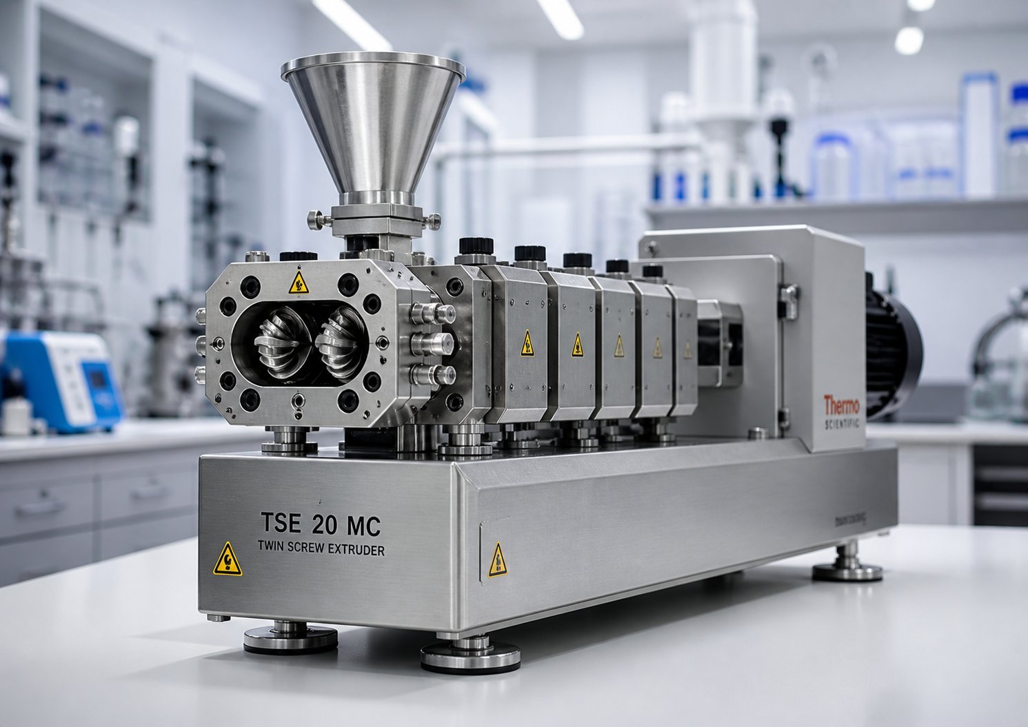
What Is a Lab Scale Twin Screw Extruder and Why It Matters
Imagine spending months developing a new polymer blend, only to realize the extruder specs you relied on were misunderstood from the start. It happens more often than you'd think. Before diving into the specs researchers commonly get wrong, you need a solid foundation — a clear picture of what a lab scale twin screw extruder actually is and who it serves.
Defining the Lab Scale Twin Screw Extruder
A lab scale twin screw extruder is a compact, research-grade extrusion system that uses two intermeshing screws inside a modular barrel to melt, mix, and process materials in small batches — typically 0.5 to 20 kg/h — for formulation development, process feasibility studies, and material screening.
That definition captures the essentials, but a few details set this equipment apart from its industrial counterparts. A laboratory twin screw extruder features screw diameters usually ranging from 10 to 27 mm, a footprint small enough to fit inside a standard research lab, and a fully modular architecture. Screw elements, barrel segments, and die heads can all be swapped out quickly, letting researchers iterate on process designs without lengthy downtime.
Production-scale twin screw extruders, by contrast, run screw diameters of 40 mm and above with throughputs measured in hundreds or thousands of kilograms per hour. They're engineered for stability and uptime — not flexibility. A laboratory scale extruder flips that priority. Flexibility comes first because every run could involve a different resin ratio, filler loading, or additive package.
Why Lab Scale Extrusion Matters for R&D
Why does any of this matter? Because nearly every material that reaches commercial production was first validated on a lab extruder. These machines serve as the critical bridge between a theoretical formulation on paper and a proven, scalable process. With raw material batches as small as 500 grams, researchers can test dozens of formulations without burning through expensive specialty resins or rare additives.
The audiences relying on this equipment span a surprisingly broad range of disciplines:
- Polymer researchers — developing nanocomposites, compatibilized blends, and masterbatch formulations
- Pharmaceutical formulators — creating amorphous solid dispersions via hot-melt extrusion
- Food technologists — engineering texturized proteins and encapsulated ingredients
- Materials engineers — compounding biodegradable polymers, battery electrode pastes, and recycled feedstocks
Each of these fields demands precise control over temperature, shear, and residence time — and a laboratory extruder delivers exactly that at a scale where mistakes are affordable. The real challenge, though, isn't just picking any twin screw extruder off a spec sheet. It's understanding how single screw and twin screw architectures differ at lab scale, and why that choice shapes every result you'll generate downstream.
Single Screw vs Twin Screw Extruder at Lab Scale
Choosing between a single screw and a twin screw architecture is the first decision that shapes your entire research workflow. Get it wrong, and you'll either lack the mixing intensity your formulations demand or overspend on capability you don't need. Surprisingly, many researchers default to one or the other based on familiarity rather than a clear understanding of the mechanical differences. Here's what actually separates these two screw extruder types at lab scale — and why it matters for your results.
How Single and Twin Screw Mechanisms Differ
A single screw extruder relies on one helical flight rotating inside a smooth barrel. Material moves forward primarily through frictional drag between the polymer melt and the barrel wall. Picture it this way: the barrel acts like a stationary nut, and the rotating screw pushes material forward the same way a bolt advances through a fixed thread. Shear rate peaks at the barrel surface and drops toward the screw root, creating a velocity gradient across the channel depth. This stratification means the polymer in a single screw channel tends to stay in roughly the same radial position as it travels downstream, making thorough full-channel mixing difficult to achieve.
Twin screw extruders change this dynamic fundamentally. Two intermeshing screws — whether co-rotating or counter-rotating — transfer material from one screw channel to the other multiple times along the barrel length. Each transfer event forces the entire melt through a narrow intermeshing zone, applying intense localized shear to a small portion of the polymer before releasing it back into the opposing channel. The result? Both dispersive mixing (breaking down agglomerates and droplets) and distributive mixing (spreading components uniformly) happen far more efficiently than anything a single screw can deliver.
There's another mechanical advantage that often goes unappreciated. In a fully intermeshing design, the screws wipe each other's surfaces continuously — like two gears scraping residual material off one another. This self-wiping behavior prevents stagnant zones where polymer could thermally degrade, and it makes product changeovers between formulations faster and cleaner. For a lab running dozens of different material combinations per week, that self-cleaning capability saves hours of downtime.
When to Choose Twin Screw Over Single Screw at Lab Scale
Does every lab need twin screw extrusion? Not necessarily. Single screw lab extruders still earn their place in certain workflows. If your research involves straightforward melt rheology studies on a single polymer, film or sheet prototyping with well-established formulations, or basic extrusion trials where intense mixing isn't the goal, a single screw machine delivers simpler operation and often a lower equipment cost.
The calculus shifts decisively toward twin screw extruders whenever your work involves multi-component systems. Compounding polymer blends with compatibilizers, dispersing nanofillers into a matrix, screening drug-polymer ratios for hot-melt extrusion, or running reactive extrusion with precise residence time control — these tasks demand the kind of mixing performance that only a double screw extruder architecture can provide. The ability to run starve-fed, where throughput is controlled independently of screw speed, gives researchers an additional degree of freedom that single screw machines simply cannot match.
The table below puts these differences side by side across the criteria that matter most for lab-scale research decisions:
| Criteria | Single Screw Lab Extruder | Twin Screw Lab Extruder |
|---|---|---|
| Mixing Capability | Limited; primarily melt homogenization with optional add-on mixers | Excellent dispersive and distributive mixing through intermeshing screw-to-screw transfer |
| Material Versatility | Best suited for single-polymer or simple blend processing | Handles multi-component systems, high-filler loadings, and reactive formulations |
| Throughput Flexibility | Output coupled to screw speed; limited independent control | Starve-fed operation decouples throughput from screw speed for independent control |
| Residence Time Control | Narrow adjustment range; largely determined by screw geometry | Broad adjustment via screw speed, feed rate, and modular element configuration |
| Self-Cleaning Ability | Poor; material stagnation common in channel dead zones | Excellent; fully intermeshing screws continuously wipe surfaces, reducing degradation risk |
| Typical Lab Applications | Melt rheology studies, simple film/sheet prototyping, established formulation trials | Compounding, masterbatch development, reactive extrusion, pharmaceutical HME, nanocomposite dispersion |
Notice a pattern? Every criterion tied to mixing quality, process flexibility, and formulation complexity favors the twin screw design. That's exactly why twin screw extruders have become the dominant platform in R&D compounding labs, pharmaceutical development centers, and advanced materials research groups worldwide. A single screw extruder processes material — a twin screw extruder lets you engineer it.
Still, selecting the twin screw path opens another question that many researchers gloss over too quickly: should those two screws rotate in the same direction or in opposite directions? The answer depends on your specific materials and process goals — and the differences between co-rotating and counter-rotating configurations run deeper than most spec sheets reveal.
Co-Rotating vs Conical Twin Screw Configurations Explained
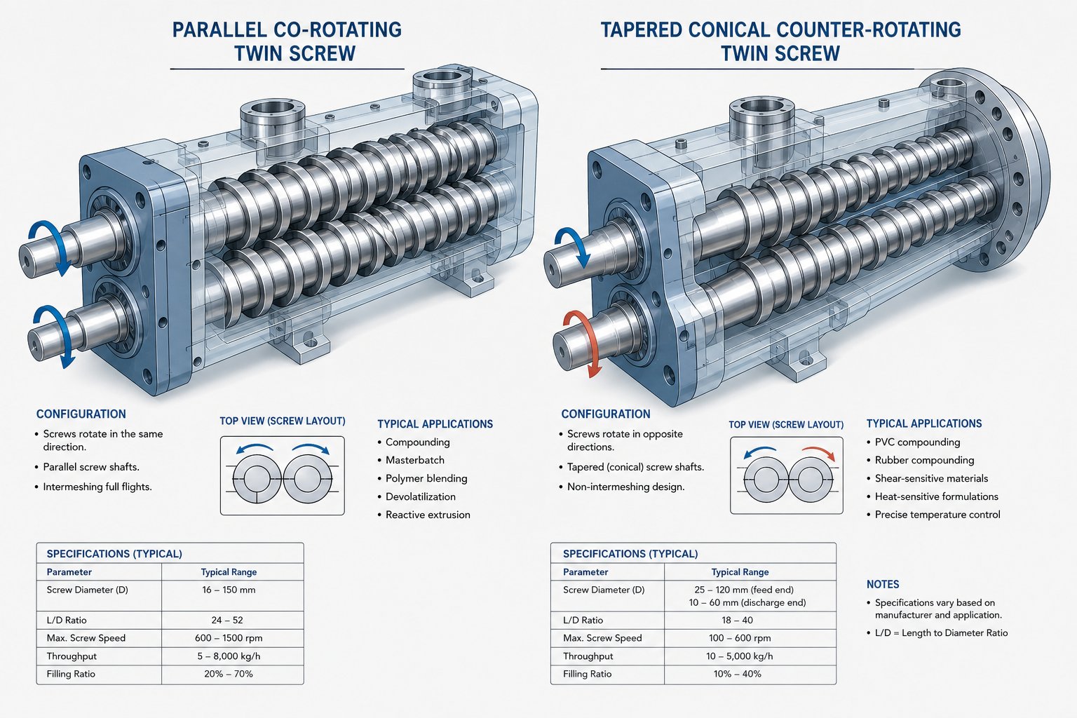
The direction those two screws rotate — and the physical shape they take — fundamentally changes the flow field inside the barrel. Two configurations dominate the lab-scale landscape: the co-rotating parallel twin screw extruder and the counter-rotating design, which often appears in a conical form factor. Picking the wrong one doesn't just reduce efficiency; it can make certain experiments impossible altogether.
Co-Rotating Parallel Twin Screw Extruders
In a co-rotating twin screw extruder, both screws spin in the same direction with a fully intermeshing geometry. Material entering one screw channel gets forcibly handed off to the opposite screw at the intermeshing zone, creating a figure-eight flow path that repeatedly splits and recombines the melt. This constant transfer generates intense shear fields both between the screws and between each screw and the barrel wall, while kneading blocks add elongational flow for even deeper mixing.
What makes this configuration so popular in R&D? Consider the practical advantages:
- Self-wiping geometry — the matching screw profiles continuously scrape residual material off each other, virtually eliminating stagnant zones where heat-sensitive polymers could degrade
- High-speed operation — because self-wiping prevents pressure peaks in the intermeshing zone, co-rotating screws can run at significantly higher RPMs than counter-rotating designs, translating to greater energy input and mixing intensity
- Narrow residence time distribution — the open figure-eight flow pattern and absence of dead zones keep all material moving through the barrel at a consistent pace, which is critical for reactive extrusion and thermally sensitive formulations
- Modular screw design freedom — conveying elements, kneading blocks, and mixing discs can be freely combined on splined shafts, letting researchers tailor energy input location and magnitude for each specific material system
- Starve-fed flexibility — throughput is controlled by the feeder, not screw speed, giving independent control over shear and output rate
These strengths explain why the parallel twin screw extruder in co-rotating configuration has become the default platform for polymer compounding, nanocomposite dispersion, pharmaceutical hot-melt extrusion, and reactive processing at lab scale. When your research demands precise control over mixing intensity and thermal history, this is the twin-screw extruder architecture that delivers.
Conical and Counter-Rotating Configurations
Counter-rotating twin screw extruders flip the rotation direction so the screws turn toward each other at the top of the intermeshing zone. Material gets drawn in and compressed between the screws through a calendering effect — think of two rollers squeezing dough. The result is lower shear stress and reduced shear-induced heat generation compared to the co-rotating type.
The conical twin screw extruder is a specialized counter-rotating variant where the screws taper from a large diameter at the feed end to a smaller diameter at the discharge. This geometry naturally builds pressure as material advances toward the die, making it especially effective for direct extrusion of finished profiles. Key strengths of conical and counter-rotating designs include:
- Low-shear, gentle mixing — ideal for thermally sensitive materials like rigid PVC, where excessive shear triggers degradation
- High pressure generation — the tapered barrel of conical designs compresses material progressively, enabling stable forming of pipes, sheets, and complex profiles without a separate melt pump
- Positive displacement conveying — material transport depends directly on screw rotation rather than frictional properties, delivering consistent output even with difficult-to-feed formulations
- Effective dispersive mixing through calendering — the compressive and elongational deformation at the intermeshing region disperses additives under gentle conditions, which suits PVC formulations that need moderate rather than aggressive dispersion
Parallel counter-rotating designs also exist, offering longer L/D ratios than conical versions. These prove useful for high-filler-loading PVC compounds — for instance, formulations with 100 phr calcium carbonate — where extended barrel length ensures thorough plasticization and better filler coating.
So which configuration should you choose? If your lab focuses on compounding, reactive extrusion, pharmaceutical HME, or any multi-component formulation development, a co-rotating design is almost certainly the right call. If your research centers on PVC processing, profile extrusion, or materials demanding minimal thermal exposure, a conical or counter-rotating machine earns its place. Most modern lab-scale compounding and pharmaceutical work defaults to co-rotating — but understanding why the alternative exists prevents costly mismatches between your equipment and your research objectives.
Whichever direction the screws turn, though, the real versatility of a lab-scale twin screw system lives in something even more granular: the individual screw elements and barrel segments that snap together to create your process. The taxonomy of these modular components is where most specification misunderstandings begin.
Modular Screw Elements and Barrel Design for Lab Extrusion
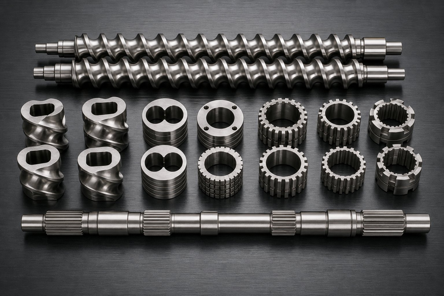
Here's a scenario most researchers recognize: you unbox a new twin screw extruder lab scale system, and inside the accessories case sits a bewildering collection of metal elements — short discs, helical flights of different pitches, toothed rings, and reverse-threaded segments. No single combination is "correct." Each arrangement creates a fundamentally different process. Understanding what these pieces do — individually and in sequence — is the knowledge gap that separates productive lab extrusion from frustrating trial-and-error.
Every element in a twin screw and barrel system slides onto a splined shaft, locked in position by keyways that transmit torque from the gearbox. You can rearrange the entire screw profile in under an hour on most lab-scale machines, swapping element positions, replacing a kneading block with a conveying section, or adding a reverse element to create a melt seal. This modularity is the defining advantage of lab-scale twin screw systems — it lets you iterate on screw design as fast as you can generate new hypotheses.
Screw Element Types and Offset Angle Effects
Think of screw elements as falling into three families: conveying, kneading, and specialized mixing. Each family controls a different aspect of how material moves, melts, and mixes inside the twin screw barrel.
Conveying elements are the workhorses of material transport. They resemble traditional helical screws with a defined pitch — the axial distance between consecutive flights. Forward-pitch conveying elements push material toward the die, while reverse-pitch elements push it backward relative to screw rotation. Why would you ever push material backward? Because reverse elements create a pressure dam upstream, increasing fill level and residence time in the preceding zone. This is exactly how researchers build melt seals ahead of vacuum venting ports or force material to spend more time in a mixing section.
Pitch size matters too. Larger pitch moves material forward aggressively with minimal compression — ideal for the feed zone where you want to grab pellets or powder quickly. Smaller pitch slows transport and builds pressure, which is what you need near the die for stable metering and consistent output.
Kneading blocks are where the real mixing action happens. Each block consists of multiple elliptical discs stacked on the shaft, with each disc offset from its neighbor by a specific stagger angle. That angle is the single most important variable controlling mixing behavior:
- 30° offset (forward stagger) — promotes forward conveying while splitting and recombining the melt repeatedly. Shear intensity stays moderate, making this the go-to choice for distributive mixing. You'll use these when blending polymers of similar viscosity or distributing pre-dispersed additives without generating excessive heat.
- 60° offset (moderate stagger) — reduces net forward conveying and increases back-mixing. Shear intensity rises noticeably. These elements sit in the middle ground — useful when you need more aggressive mixing than 30° blocks provide but want to avoid the extreme stress of a 90° configuration.
- 90° offset (neutral stagger) — delivers zero net conveying. Material oscillates back and forth across the block, exposing every melt stream to intense shear and pressure fluctuations. This is the dispersive mixing workhorse, designed to break apart hard agglomerates of pigments, carbon black, or nanofiller clusters. The tradeoff? Significantly higher melt temperature and torque demand.
Disc width within a kneading block adds another layer of control. Narrower discs create more frequent changes in the cross-sectional flow pattern, generating higher local pressure fluctuations and stronger dispersive action. Wider discs smooth out those fluctuations, favoring gentler distributive mixing. You can picture it this way: narrow discs chop the flow into rapid pulses, while wide discs let it glide through more gradually.
Specialized mixing elements round out the toolkit. Toothed mixing discs (sometimes called gear or TME elements) feature interrupted geometries that repeatedly divide and recombine melt streams without the high shear stress of kneading blocks. Distributive mixing elements with offset channels or lobes achieve thorough spatial homogenization while keeping temperature rise minimal — particularly valuable for heat-sensitive pharmaceutical formulations or bio-based polymers. Interrupted or "comb" conveying elements offer a hybrid approach, adding mild mixing action to a conveying section without the full shear commitment of a kneading block.
The table below maps each element type to its function, shear intensity, and typical placement along the screw:
| Element Type | Primary Function | Shear Intensity | Typical Placement |
|---|---|---|---|
| Conveying (forward pitch) | Material transport, pressure build-up, solids feeding | Low | Feed zone, metering zone, between mixing sections |
| Kneading block 30° | Distributive mixing, gentle blending | Low to moderate | First mixing zone after initial melting |
| Kneading block 60° | Combined distributive and dispersive mixing | Moderate | Intermediate mixing zones, filler wetting stages |
| Kneading block 90° | Intensive dispersive mixing, deagglomeration | High | Primary dispersion zone for agglomerate breakup |
| Toothed/distributive mixing | Flow splitting and recombination with low shear | Low to moderate | Final homogenization zone, heat-sensitive applications |
| Reverse (conveying or kneading) | Melt seal creation, pressure dam, increased residence time | Moderate to high | Before vent ports, after side feeders, end of mixing zones |
A well-designed screw profile doesn't rely on one element type alone. It layers conveying, kneading, and mixing elements in a deliberate sequence — feeding first, then melting, then mixing with increasing intensity, then venting, and finally metering under stable pressure. Changing just one kneading block from 30° to 90° in the wrong position can spike melt temperature by 20°C or more, turning a successful run into a degraded mess.
Modular Barrel Zones and Their Functions
The screw profile only tells half the story. Every element operates inside a barrel extruder section that controls the thermal environment — and in a modular barrel design, each section is independently heated and cooled.
Most lab-scale twin screw extruders use segmented barrel sections, typically four to six L/D each, bolted together to form the full processing length. Each segment contains its own electric heating bands and liquid cooling channels, giving you independent temperature control zone by zone. But temperature management is only part of what barrel modularity delivers. Different barrel sections serve structurally different purposes depending on whether they're open or closed.
Here's how the primary barrel zone functions break down:
- Feeding zone (open barrel) — positioned at barrel section one, this segment features an opening through which pellets, powders, or granules drop into the screw channel. For low-bulk-density powders that trap air, a back-venting setup using two open barrel sections at the first positions can improve feeding stability by allowing entrained air to escape upstream.
- Melting and conveying zone (closed barrel) — fully enclosed sections that transfer heat from barrel walls to the material while conveying elements compress and advance the polymer. The figure-eight shaped bore of a co-rotating barrel extends contact surface area, promoting efficient heat transfer and consistent melting.
- Mixing zone (closed barrel) — closed sections where kneading blocks and mixing elements operate on fully molten material. Independent cooling on these segments is critical because viscous dissipation from shear can push melt temperature well above the barrel set point.
- Side-feeding zone (open barrel) — a secondary figure-eight opening on the barrel side connects to a side feeder for downstream introduction of fillers, glass fibers, or shear-sensitive additives. Adding fillers downstream — after the polymer is fully melted — prevents abrasive wear in the melting zone and protects fragile fiber lengths from excessive breakage.
- Venting zone (open barrel) — open ports allow atmospheric or vacuum degassing. Positioned near the discharge end, vacuum ports draw out moisture, residual monomers, or solvents. Screw elements in this zone are configured to reduce fill level and pressure, creating the exposed melt surface area needed for volatiles to escape without melt extruding through the vent port.
- Metering zone (closed barrel) — the final closed section before the die, where conveying elements with tight pitch build stable, uniform pressure for consistent output and dimensional control of the extrudate.
What makes this modularity so powerful at lab scale? Imagine you're running a filled polymer compound and realize you need a liquid injection port for a coupling agent. On a production barrel extruder with a fixed configuration, that's a major retrofit. On a modular lab machine, you unbolt one closed barrel section, replace it with a liquid injection barrel, reconnect the heating lines, and you're running again — often within an afternoon. The same logic applies when adding a second vent port for a formulation with higher moisture content or repositioning a side feeder to optimize filler dispersion.
This combination of modular screw elements and modular barrel sections is what transforms a lab-scale twin screw extruder from a simple processing tool into a configurable research platform. Every zone — from feed throat to die face — can be tailored to match the exact thermal, mechanical, and chemical demands of your material system. The challenge, of course, is knowing which specifications to look for when evaluating these machines in the first place, and that's where many researchers start making costly assumptions about numbers on a data sheet.
Key Technical Specifications Every Researcher Should Evaluate
A data sheet for a twin screw extruder machine can list a dozen parameters, each with impressive-sounding numbers. Bigger motor. Higher RPM. More barrel zones. The temptation to chase the largest values is real — and it's one of the most common mistakes researchers make when selecting laboratory extruders. Every specification on that sheet exists in relationship to the others, and the right combination depends entirely on what you're trying to accomplish. Here's a breakdown of the specs that actually matter, what they control, and how to match them to your research rather than to your ego.
Critical Specifications and What They Mean
Screw diameter is the anchor specification — nearly every other parameter scales from it. Lab-scale machines typically range from 10 to 27 mm, while pilot-scale equipment extends to roughly 40 mm. A smaller diameter like 11 or 16 mm keeps material consumption extremely low, sometimes under 100 grams per trial, which is essential when working with expensive APIs or novel polymers. Larger lab diameters around 20-27 mm process enough material for meaningful downstream testing — pellet characterization, mechanical test specimens, or film trials — while still qualifying as a benchtop twin screw extruder that fits comfortably in a standard laboratory space.
L/D ratio — the barrel length divided by screw diameter — determines how many functional zones you can fit along the process section. Most lab-scale twin-screw extruder machines offer L/D ratios between 25:1 and 40:1, with 40:1 becoming increasingly standard. Why does length matter? Each functional stage — feeding, melting, mixing, side feeding, venting, pressure building — occupies several diameters of screw length. A 25:1 barrel might accommodate basic melting and a single mixing zone. A 40:1 configuration provides enough real estate for multi-stage compounding with downstream filler addition, vacuum devolatilization, and thorough homogenization before the die. Reactive extrusion and pharmaceutical HME formulations, where precise residence time and multiple processing stages are critical, benefit directly from longer L/D ratios.
Torque rating is arguably the most underestimated specification. Torque — measured in Newton-meters per shaft — represents the rotational force available to shear, melt, and transport material through the screw channels. High-viscosity engineering polymers like PEEK or heavily filled compounds with 60% mineral loading demand substantial torque reserves. If your process consistently runs above 80% of available torque, you're operating dangerously close to mechanical safety limits, risking shaft overload shutdowns in the middle of a critical experiment. Reference data from equipment manufacturers shows lab-scale torque ratings ranging from roughly 6 N.m per shaft on an 11 mm machine up to 140 N.m or more on a 26 mm unit.
Torque also connects directly to specific energy input — the kilowatts of mechanical energy delivered per kilogram of throughput. Specific energy is calculated from applied motor power (factoring in percent torque, running RPM versus maximum RPM, and gearbox efficiency) divided by throughput in kg/h. This metric lets you compare processes across different machine sizes and is essential for scale-up. If you track nothing else during a lab trial, track specific energy — it becomes the universal translator between your benchtop extruder and a production-scale line.
Maximum screw speed ranges from approximately 200 RPM on older or budget lab units to 1000-1200 RPM on modern high-speed energy input designs. Higher RPM doesn't automatically mean better mixing. It means more shear energy is available when you need it. For low-viscosity polymer blends, moderate speeds of 200-400 RPM may deliver perfectly adequate mixing. For dispersing nano-fillers or breaking pigment agglomerates, pushing toward 600-1000 RPM with a well-designed kneading section can make the difference between a poorly dispersed sample and a publication-quality result. The key is that screw speed interacts with feed rate — a topic we'll explore shortly.
Number of independent barrel heating zones determines how precisely you can shape the thermal profile along the process section. A 16 mm lab machine with 40:1 L/D typically offers 4 to 6 independently controlled zones, while a 26 mm unit may provide 8 to 10 zones. Each zone features its own PID-controlled heater and liquid cooling channel. More zones give you finer resolution — essential for materials with narrow processing windows or when you need a steep temperature ramp followed by a cooling step before the vent port.
Maximum barrel temperature usually sits between 300°C and 450°C depending on the machine design. Standard thermoplastic compounding rarely exceeds 300°C, but researchers working with high-performance polymers like polyimides, PEEK, or PPS need equipment rated to 400°C or above. Pharmaceutical HME applications typically operate well below 200°C, so maximum temperature is less of a concern — but the precision of control within that lower range becomes critical.
Throughput range defines the minimum and maximum output your machine can sustain. Lab-scale units span roughly 0.2 kg/h on the smallest 11 mm platforms to 20-50 kg/h on larger 26 mm systems. The minimum matters as much as the maximum. If your formulation uses a rare polymer available only in 200-gram batches, a machine that can't run stably below 2 kg/h wastes material you can't afford to lose.
The following table consolidates these specifications into a quick-reference guide:
| Parameter | Typical Lab-Scale Range | Why It Matters |
|---|---|---|
| Screw Diameter | 10-27 mm (up to 40 mm pilot overlap) | Determines free volume, material consumption per run, and scale-up pathway |
| L/D Ratio | 25:1 to 40:1 | Controls number of functional zones available for melting, mixing, venting, and metering |
| Torque per Shaft | 6-140+ N.m | Limits processing of high-viscosity or highly filled materials; drives specific energy input |
| Motor Power | 2-37 kW | Sets upper bound for mechanical energy input; must match torque and speed requirements |
| Maximum Screw Speed | 200-1200 RPM | Governs available shear rate and mixing intensity; higher speeds suit dispersive tasks |
| Barrel Heating Zones | 4-10 independent zones | Determines thermal profile resolution; more zones enable tighter temperature control |
| Maximum Barrel Temperature | 300-450°C | Defines upper material compatibility; critical for high-performance polymer research |
| Throughput Range | 0.2-50 kg/h | Dictates minimum sample size and maximum output; must match material availability and downstream needs |
Matching Extruder Specs to Your Research Goals
Reading a spec table is one thing. Translating it into a purchasing decision is another. The most productive approach is to start with your materials and objectives, then work backward to the hardware.
Running pharmaceutical hot-melt extrusion with gram-scale API batches? Prioritize a small screw diameter (11-16 mm), a 40:1 L/D for multi-stage processing, and tight temperature control across at least six zones — throughput capacity beyond 5 kg/h is irrelevant. Developing highly filled engineering compounds with 50-60% mineral content? Torque reserve becomes your limiting factor. A 20-26 mm machine with strong torque density and motor power in the 7-37 kW range prevents mid-run shutdowns when viscosity spikes during filler incorporation.
Researchers focused on reactive extrusion — where monomer conversion or grafting reactions need precise residence time — should look for the longest L/D available combined with high screw speed capability. The extra barrel length gives room for reaction, mixing, and devolatilization stages in sequence, while high RPM paired with low feed rate creates the extended residence time these chemistries demand.
One pattern holds across every application: the target production output should sit comfortably inside the machine's stable operating window, never at the absolute edge of its torque, thermal, or throughput limits. A line that constantly runs near maximum capacity produces unstable data and accelerated wear — neither of which belongs in a research program designed to generate reliable, scalable results.
Specifications set the boundaries of what's possible. But knowing which numbers to prioritize only gets you halfway. The real performance of any twin screw extruder machine emerges from how those specs translate into actual applications — and the range of industries now relying on lab-scale extrusion stretches far wider than most newcomers expect.
Industry Applications from Polymers to Pharmaceuticals
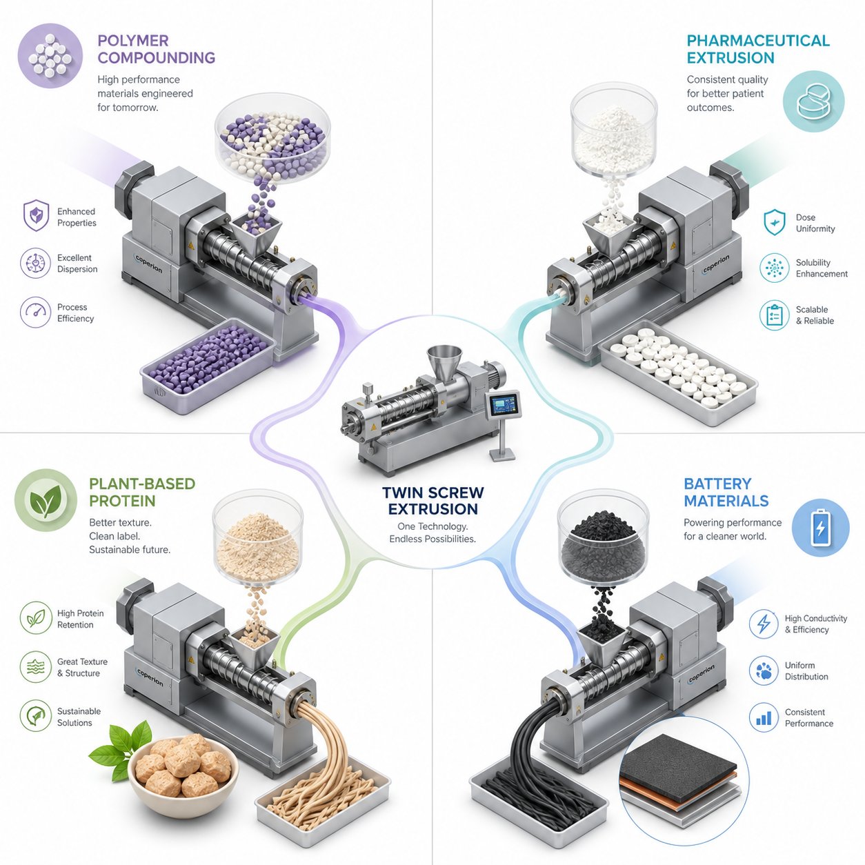
Specs on a data sheet tell you what a machine can do mechanically. Applications tell you what it actually accomplishes in practice. The gap between the two is where real research value lives — and the range of industries now leveraging lab-scale twin screw extrusion might surprise you. What started as a polymer compounding tool has evolved into the go-to platform for pharmaceutical formulators, food scientists, and battery researchers alike. The common thread? Every one of these fields needs precise, repeatable mixing at small batch sizes — often under 500 grams — with the flexibility to change screw configurations between experiments in under an hour.
That combination of low material consumption and rapid reconfiguration makes the twin screw extruder lab scale system uniquely suited for design-of-experiment (DOE) workflows. Instead of committing kilograms of expensive raw material to a single trial, researchers can run 10, 20, even 50 formulation variations in a single week. Here's how that capability translates across the industries driving adoption.
Polymer Compounding and Masterbatch Development
Polymer research remains the largest user base for lab-scale twin screw extrusion — and for good reason. A compounding twin screw extruder delivers the dispersive and distributive mixing intensity needed to transform raw resins, fillers, and additives into precisely engineered compounds. The applications span nearly every corner of polymer science:
- Masterbatch development — color concentrates, additive packages, and UV stabilizer masterbatches require uniform pigment or additive dispersion at loadings of 20-70%. A polymer extruder running at lab scale lets colorists screen dozens of pigment-to-carrier ratios in a single session, evaluating dispersion quality through let-down testing and colorimetric analysis without consuming production-scale resin volumes.
- Nanocomposite dispersion — dispersing nanoclays, carbon nanotubes, or graphene into a polymer matrix demands high specific energy and carefully tuned kneading block sequences. Lab-scale machines allow researchers to isolate the effect of screw configuration on nanoparticle exfoliation and distribution, measuring improvements through TEM imaging and rheological percolation thresholds.
- Compatibilizer screening — when blending immiscible polymers like PP/PA or PE/PET, reactive compatibilizers (typically maleic anhydride-grafted polyolefins) need to be evaluated at varying concentrations. A twin screw compounding extruder at lab scale makes it practical to test five or six compatibilizer levels in a morning, then assess blend morphology by SEM that afternoon.
- Filled compound optimization — mineral fillers like talc, calcium carbonate, or glass fibers affect stiffness, impact strength, and warpage. Using a compounding extruder at lab scale, researchers systematically vary filler loading, particle size, and surface treatment while keeping all other process parameters constant — the kind of controlled experimentation that production-scale equipment simply cannot support economically.
Across all of these applications, the screw plastic extruder platform's modularity proves decisive. Swapping a 30-degree kneading block for a 90-degree element in the primary mixing zone can transform dispersion outcomes without changing a single raw material. That kind of isolated variable testing is the backbone of rigorous polymer R&D.
Pharmaceutical Hot-Melt Extrusion Applications
Pharmaceutical development has arguably been the fastest-growing application sector for lab-scale twin screw extrusion over the past decade. Hot-melt extrusion (HME) is now recognized as an emerging continuous manufacturing platform by the FDA and regulatory bodies worldwide, and the lab-scale twin screw extruder has become the standard development tool for formulation scientists working in this space.
- Amorphous solid dispersion (ASD) development — many drug candidates suffer from poor aqueous solubility. HME disperses the active pharmaceutical ingredient (API) molecularly within a polymeric carrier like HPMC-AS, PVP-VA, or Soluplus, creating an amorphous solid dispersion that dramatically improves bioavailability. Lab-scale machines let formulators screen multiple polymer-API combinations and drug loadings using just grams of expensive compound, then characterize each extrudate for crystallinity via DSC and XRD before committing to larger trials.
- Continuous twin screw granulation — an alternative to traditional wet or dry granulation, twin screw granulation uses the extruder's mixing and conveying action to produce granules with controlled size distribution and improved flowability. Research published in Pharmaceutics has shown that barrel fill level, screw speed, and liquid binder addition rate all significantly influence granule properties and downstream tablet tensile strength — variables most efficiently explored on lab-scale equipment.
- Drug-polymer miscibility screening — before investing in full formulation development, researchers need to confirm that their API and carrier polymer are thermodynamically miscible at the target drug loading. Lab-scale extruders with precise temperature profiling and short residence times allow rapid screening of multiple polymer candidates in a single day, with DSC analysis of each extrudate revealing glass transition behavior indicative of miscibility.
What makes the extruder for polymer and pharmaceutical applications alike is the solvent-free, continuous nature of the HME process. Traditional solvent-based techniques for creating solid dispersions introduce drying steps, residual solvent concerns, and batch-to-batch variability. A twin screw HME process eliminates all three. And because the process combines fewer production steps with inherent scalability, formulations validated on a 16 mm lab platform can transfer to 24 mm or 27 mm pharmaceutical-grade production extruders with minimal reformulation.
Food Technology and Advanced Materials Research
Beyond polymers and pharma, two rapidly expanding application areas demonstrate just how versatile the lab-scale screw plastic extruder platform has become.
Food technology applications leverage the twin screw extruder's ability to apply controlled shear and heat to biopolymers and protein systems:
- Texturized protein development — plant-based meat alternatives rely on high-moisture extrusion to transform soy, pea, or wheat protein isolates into fibrous, meat-like structures. Lab-scale trials let food scientists explore protein blend ratios, moisture levels, and cooling die temperatures before scaling to production.
- Encapsulation — flavors, probiotics, and bioactive compounds can be encapsulated within a starch or protein matrix during extrusion, protecting sensitive ingredients from oxidation or gastric degradation. Small-batch trials on lab equipment enable rapid iteration of wall material composition and core-to-wall ratios.
- Starch modification — thermomechanical treatment in a twin screw extruder gelatinizes, degrades, or chemically modifies native starch to create pregelatinized starches, thermoplastic starch blends, or starch-based packaging precursors.
Advanced materials research pushes the platform into territory that would have seemed unlikely a decade ago:
- Battery electrode paste compounding — twin-screw extrusion offers a continuous alternative to batch planetary mixing for cathode and anode slurry preparation. Lab-scale extruders with 11 mm screw diameters can process novel electrode formulations using as little as 100 grams of active material, enabling researchers to evaluate new cathode chemistries or binder systems without committing large quantities of expensive precursors. The superior dispersion quality and narrower particle size distribution achievable through twin screw mixing translate directly to improved electrochemical cell performance.
- Biodegradable polymer blending — PLA/PBAT blends, PHA-based compounds, and starch-polyester combinations all require careful compatibilization. Lab-scale compounding trials identify optimal blend ratios and compatibilizer levels before pilot-scale validation.
- Recycled material upcycling — post-consumer recycled plastics vary widely in composition and contamination level. Researchers use lab-scale twin screw extrusion to evaluate stabilizer packages, chain extenders, and filler additions that restore or enhance mechanical properties of degraded recyclate streams.
Across every one of these sectors, a consistent theme emerges: the lab-scale twin screw extruder succeeds not because it processes large volumes, but precisely because it doesn't. Small batches, fast changeovers, and modular flexibility let researchers isolate variables and generate statistically meaningful datasets in days rather than weeks. The machine becomes less of a processing tool and more of an analytical instrument — one that answers the question "what happens if I change this one thing?" with physical evidence instead of simulation.
Generating that evidence reliably, though, requires more than good equipment and interesting materials. It demands a working understanding of how process parameters interact — because screw speed, feed rate, barrel temperature, and screw configuration don't operate independently. They form a coupled system where adjusting one variable inevitably shifts the others.
Process Parameters and Practical Operating Guidelines
You've selected your screw elements, configured your barrel zones, and loaded your hopper with material. The machine is ready. But the moment you press start, four variables begin interacting in ways that can either produce publication-quality extrudate or generate a barrel full of degraded polymer — and the difference often comes down to understanding how those variables talk to each other.
In laboratory extrusion, the four primary controllable inputs are screw speed (RPM), feed rate (gravimetric or volumetric), barrel temperature profile, and screw configuration. Each one individually seems straightforward. Screw speed controls how fast the screws rotate. Feed rate sets how much material enters per unit time. Temperature profiles dictate thermal energy input from the barrel walls. Screw configuration determines where and how intensely mixing occurs. The complexity — and the source of most extrusion lab mistakes — emerges from their interactions.
How Screw Speed, Feed Rate, and Temperature Interact
Here's the concept that trips up more new researchers than any other specification error:
In starve-fed twin screw extrusion, throughput is controlled by the feeder, not the screw speed. This decoupling means screw RPM can be increased without increasing output — giving independent control over mixing intensity and residence time.
This principle, well established in extrusion research, fundamentally separates twin screw operation from single screw behavior. In a flood-fed single screw extruder, the hopper gravity-feeds material into a fully packed screw channel, and output rises roughly proportionally with screw speed. In a starve-fed extruder system, a gravimetric or volumetric feeder meters material at a controlled rate below the screw's maximum conveying capacity. The screw channel remains only partially filled in the conveying zones, and pressure builds exclusively in the kneading blocks and metering section near the die.
Why does this matter practically? Because it gives you two independent control levers instead of one. Imagine you're compounding a nanocomposite and your current screw speed of 300 RPM delivers inadequate dispersion. In a flood-fed setup, increasing RPM also increases throughput — changing your residence time, fill level, and thermal history simultaneously. In a starve-fed twin screw extruder, you can push screw speed to 500 RPM while holding feed rate constant. The result? Higher shear rate and greater specific mechanical energy (SME) input in the kneading zones, without changing throughput. Residence time may shift slightly because faster screw rotation moves material through partially filled conveying zones more quickly, but the effect is far smaller than what screw speed changes produce in flood-fed operation.
Research published on twin-screw compounding parameters confirms this relationship quantitatively: screw speed and feed rate exert the greatest impact on melt temperature. Higher screw speeds deliver more mechanical energy in the mixing zones, raising melt temperature above barrel set points — sometimes by 20-40°C depending on polymer viscosity and screw configuration. Meanwhile, throughput has a considerable influence on residence time; increasing feed rate shortens both the average residence time and the width of the residence time distribution.
These interactions create a web of cause-and-effect that you need to navigate deliberately:
- Increasing screw speed at constant feed rate — raises shear rate and SME, reduces fill level in conveying zones, slightly decreases residence time, and elevates melt temperature through viscous dissipation. Dispersive mixing improves, but thermal degradation risk increases for heat-sensitive materials.
- Increasing feed rate at constant screw speed — raises fill level throughout the barrel, increases residence time slightly in mixing zones (more material spends time in the fully filled kneading blocks), and reduces SME because the same motor energy is now spread across more material. Mixing intensity per unit mass drops, but throughput rises.
- Raising barrel temperature — reduces polymer viscosity, which lowers torque demand and viscous heat generation. Paradoxically, setting barrel temperatures too high can sometimes reduce total melt temperature because the lower-viscosity melt absorbs less mechanical energy from the screws. This counterintuitive relationship catches many researchers off guard.
- Changing screw configuration — adding aggressive kneading blocks (90-degree offset) or reverse elements increases local fill level, residence time, and shear stress in that zone. Replacing them with gentler 30-degree blocks or distributive mixing elements has the opposite effect. Configuration changes propagate upstream and downstream — a tighter restriction in one zone raises fill level in the preceding conveying section and changes the pressure profile all the way back to the feed throat.
Temperature profiling deserves special attention because barrel set temperature and actual melt temperature are rarely the same number. In lab-scale machines with small barrel diameters, the high surface-area-to-volume ratio means barrel wall temperature strongly influences melt temperature in conveying zones. But in kneading zones — where the channel is fully filled and intense shear generates viscous heat — melt temperature can exceed barrel settings significantly. This is precisely why experienced operators always measure melt temperature at the die using an immersion thermocouple or infrared probe rather than relying on barrel zone readouts alone.
Some advanced extruder system configurations incorporate a bypass valve extrusion setup, which diverts a portion of the melt stream away from the die and recirculates it. This approach extends effective residence time without modifying screw configuration — a useful technique when reactive extrusion chemistries need more time to reach target conversion but the screw profile is already optimized for mixing. Bypass valve extrusion finds particular application in pharmaceutical HME development, where formulators need to study the effect of residence time on API-polymer interaction without altering shear history.
Operational Best Practices and Troubleshooting Tips
Theory and practice diverge most sharply during the first few minutes of a run. Here are the operational habits that separate productive extrusion lab sessions from equipment damage and wasted material:
Start low, ramp gradually. Begin with screw speed at 50-100 RPM and feed rate at the lower end of your target range. Allow the barrel to reach thermal equilibrium — which takes longer than most impatient researchers expect, often 15-20 minutes on a lab-scale machine. Gradually increase screw speed to your target while monitoring torque percentage. If torque climbs above 70-80% of the machine's rated maximum, reduce feed rate or increase barrel temperature before pushing speed higher.
Monitor melt temperature independently. Install a thermocouple probe in the die adapter or use an infrared sensor aimed at the extrudate immediately after it exits the die. The barrel zone temperature display tells you what the heaters are doing — the melt probe tells you what the material is actually experiencing. The difference between these two numbers is your viscous dissipation signal, and tracking it across experiments provides more process insight than almost any other single measurement.
Purge between formulations. When switching between material systems, flush the extruder with a compatible purge compound — typically the base polymer of your next formulation or a dedicated purging resin. Running a purge for several minutes at moderate speed clears residual material from kneading zones and the die, preventing cross-contamination that skews analytical results. For color changes, increase screw speed during the purge cycle to maximize self-wiping action in the intermeshing zones.
Record everything. Log screw speed, feed rate, barrel zone temperatures, torque percentage, die pressure, and melt temperature for every steady-state condition. These data points become indispensable during scale-up — you cannot reproduce a result on a larger machine if you don't know exactly what produced it on the small one.
Even with careful operation, problems arise. Here's a troubleshooting checklist for the issues that plague lab-scale twin screw runs most frequently:
- Torque spikes or motor overload shutdown — almost always caused by overfeeding. The feed rate exceeds what the screw profile can convey through its tightest restriction (typically a 90-degree kneading block or reverse element). Reduce feed rate by 20-30%, then verify that the feeder is delivering material consistently rather than in surges. Cold-start conditions aggravate this problem because unmelted material generates far higher viscosity and shear stress than a fully plasticized melt.
- Output surging or pulsating extrudate — usually traced to inconsistent feeding. Volumetric feeders are especially prone to surging with powders or regrind that bridge in the hopper. Switch to gravimetric (loss-in-weight) feeding for better consistency, or add a hopper agitator. Surging can also result from material slippage in the feed throat — a water-cooled feed barrel section prevents premature softening that causes pellets to stick and bridge.
- Material degradation or discoloration — excessive melt temperature from too-aggressive screw configurations, too-high RPM, or insufficient cooling in the kneading zones. Reduce screw speed first, then evaluate whether your kneading block stagger angles are more aggressive than the material requires. Replacing 90-degree kneading blocks with 60-degree elements often resolves degradation while maintaining acceptable dispersion.
- Vent flooding (material exiting through vent ports) — the screw profile upstream of the vent port is generating too much pressure, pushing melt into the vent opening instead of allowing volatiles to escape. Increase the length of the decompression zone (low-pitch or wide-pitch conveying elements) before the vent, or reduce overall fill level by lowering feed rate. Vacuum level that's too aggressive can also pull melt into the vent line.
- Poor dispersion despite adequate screw speed — the kneading section may be too short, positioned too far upstream (before material is fully melted), or configured with wrong offset angles. Ensure kneading blocks sit downstream of complete melting, and consider adding a second kneading zone with a conveying section separating the two stages.
Every one of these troubleshooting scenarios reinforces the same lesson: process parameters in a twin screw extruder lab scale system are coupled, not independent. Fixing a problem by adjusting one variable inevitably shifts others. The researchers who generate the most reliable data are the ones who change one variable at a time, document the result, and build an understanding of their specific material's response surface — not the ones who adjust three knobs simultaneously and hope for the best.
That disciplined, data-rich approach to lab operation pays its biggest dividend when the project reaches its ultimate goal: taking a validated lab-scale process and reproducing it on a larger machine. Scale-up is where careful parameter documentation either saves months of work or exposes gaps that send the team back to the beginning.
Scaling Up from Lab to Pilot to Production Extrusion
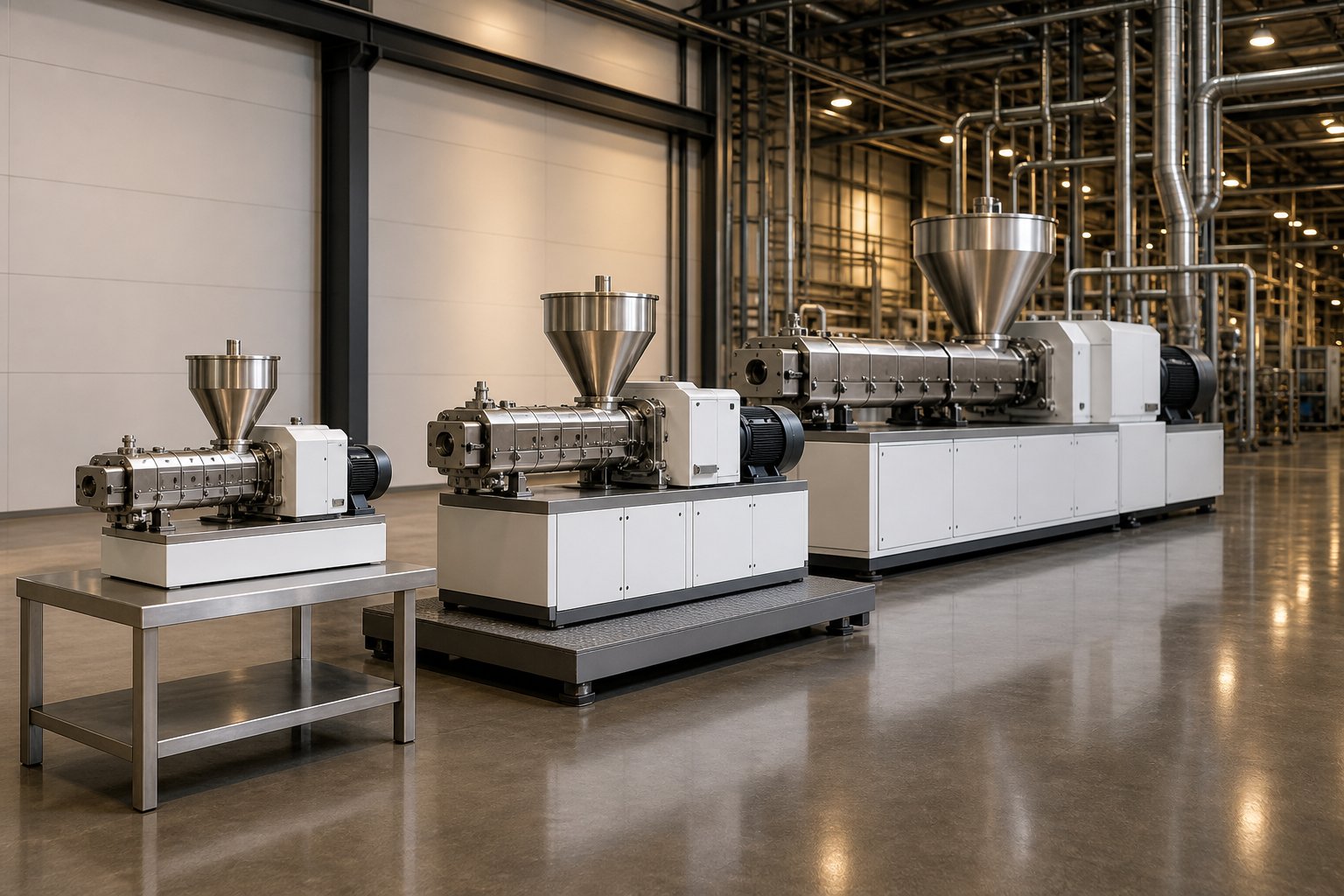
Every formulation validated on a 16 mm screw eventually faces the same question: will it behave the same way on a 40 mm machine running ten times the throughput? Scale-up is the ultimate purpose of lab-scale extrusion — and it's the stage where more projects stall than at any other point in development. The reason isn't a lack of ambition. It's a misunderstanding of what actually stays constant and what inevitably changes when you make the barrel bigger.
Twin-screw extruders are often described as geometrically similar across sizes, and that description is broadly true — a 16 mm co-rotating compounder and its 40 mm sibling share the same screw element geometry, the same intermeshing profile, and the same modular architecture. But "geometrically similar" does not mean "process identical." The physics inside the barrel shift in predictable but sometimes counterintuitive ways as diameter increases. Understanding those shifts — and planning for them before you ever turn on the larger machine — is what separates a smooth technology transfer from a costly restart.
Geometric, Thermal, and Process Similarity Principles
Scale-up theory for screw extruders rests on three pillars. Each one addresses a different dimension of the problem, and no single pillar alone guarantees success.
Geometric similarity means maintaining the same proportional relationships across equipment sizes. The L/D ratio stays constant — if your lab-scale screw profile uses a 40:1 barrel, the pilot and production machines should match that ratio. Screw element sequencing (conveying zones, kneading blocks, venting sections) is replicated in the same proportional positions along the barrel length. Die geometry scales proportionally to maintain consistent shear rate at the exit. Geometric similarity is the easiest principle to satisfy because manufacturers design their machine families around it — a double screw extruder machine at 26 mm uses the same element catalog logic as its 52 mm production counterpart.
The second pillar — thermal similarity — is where things get difficult. As Technovel's scale-up analysis explains, internal flow volume increases with the cube of the barrel inner diameter (D³), while barrel surface area increases only with the square (D²). This geometric reality means the relative effectiveness of heat transfer to the bulk of the material declines as the machine grows. A 16 mm barrel has an exceptionally high surface-area-to-volume ratio, so barrel wall temperature strongly influences melt temperature. Scale that same process to a 60 mm machine, and the barrel heaters and cooling channels have proportionally far less thermal reach into the center of the melt stream. Applying the same temperature settings and rotational conditions used on the smaller machine will not reproduce the same temperature history.
Process similarity targets the parameters that directly govern product quality: specific mechanical energy (SME), residence time distribution, melt temperature, fill level, and maximum shear stress. These are the scale-independent process responses that — when matched across equipment sizes — give you the best chance of producing equivalent material properties. Research from Merck's extrusion development team emphasizes that linking quality attributes to scale-independent responses (rather than to machine-specific input settings like RPM or barrel zone temperature) creates a control strategy that remains valid regardless of equipment brand, size, or location.
The practical scale-up sequence follows a logical progression that builds confidence at each stage:
- Establish the lab-scale baseline — run your optimized formulation on the lab machine (10-20 mm diameter) while recording specific energy, residence time, melt temperature, torque percentage, and all barrel zone temperatures at steady state. This dataset is your scale-up blueprint.
- Calculate initial pilot-scale settings — maintain the same screw speed and barrel temperature profile. Estimate pilot throughput using a volumetric scaling rule. The simplest approach uses the Schuler rule, which scales throughput by the ratio of the free volumes between the two machines. For co-rotating twin-screw extruders, throughput scaling falls somewhere between the square law (Q proportional to D²) and the cubic law (Q proportional to D³), depending on whether thermal fidelity or volumetric productivity takes priority.
- Run the pilot machine and compare process responses — measure residence time distribution and specific energy on the pilot extruder (25-40 mm). If these values diverge from your lab data, adjust feed rate first. In a documented example scaling from an 11 mm to a 16 mm compounder, the Schuler rule predicted a throughput of 3 kg/h, but matching the lab-scale residence time and specific energy actually required reducing throughput to 2.5 kg/h — a meaningful correction that would have been missed without direct measurement.
- Iterate barrel temperature to compensate for thermal scaling effects — because the larger barrel's reduced surface-area-to-volume ratio diminishes heat transfer effectiveness, you may need to adjust zone temperatures to achieve the same melt temperature profile. Cooling capacity becomes more important; barrel cooling on a production machine rarely matches the responsiveness of a lab unit.
- Validate product quality at production scale — once pilot results confirm that scale-independent responses are matched, transfer the process to production equipment (40-90+ mm). Fine-tune feed system design, vent configurations, and downstream equipment to handle the higher throughput without introducing new variability.
The following table summarizes how key characteristics shift across the three equipment scales:
| Parameter | Lab Scale | Pilot Scale | Production Scale |
|---|---|---|---|
| Screw Diameter | 10-20 mm | 25-40 mm | 40-90+ mm |
| Typical Throughput | 0.2-20 kg/h | 10-100 kg/h | 100-5,000+ kg/h |
| Primary Purpose | Formulation screening, process feasibility, DOE studies | Process validation, sample production for qualification testing | Commercial manufacturing |
| Barrel Thermal Influence | High — barrel wall temperature strongly drives melt temperature | Moderate — shear heating begins to dominate in mixing zones | Low — viscous dissipation is the primary heat source; barrel cooling effectiveness declines |
| Key Scale-Up Consideration | Collect robust baseline data: SME, residence time, melt temperature at die | Adjust throughput to match lab-scale SME and residence time; do not assume Schuler rule alone is sufficient | Redesign cooling strategy; verify feed system consistency at high rates; reassess vent capacity |
Common Scale-Up Pitfalls and How to Avoid Them
Even with the right theoretical framework, certain mistakes recur across labs and industries. Recognizing them before they cost you months of rework is half the battle.
Assuming linear throughput scaling. Researchers frequently multiply lab throughput by the cube of the diameter ratio and expect the larger machine to hit that number while maintaining quality. The cubic law represents an upper bound based purely on volumetric capacity — it ignores thermal constraints entirely. In practice, pushing throughput toward the cubic law limit raises shear heating and melt temperature because the barrel can no longer remove heat as effectively. As Technovel's engineering analysis states, the actual operating point for most twin-screw extruders sits between the square law and the cubic law, balancing productivity against quality reproducibility.
Neglecting the thermal crossover. On a 16 mm lab machine, barrel temperature settings strongly influence product temperature — sometimes more than screw speed does. Researchers calibrate their process around barrel zone set points and then discover those same set points produce completely different melt temperatures on a 40 mm pilot machine. The fix? Track melt temperature at the die — not barrel zone readings — as your primary thermal metric. This measurement transfers across scales, while barrel set points do not.
Ignoring free volume differences on mixing quality. Even geometrically similar machines from different manufacturers may have slightly different free volumes due to tolerances, flight depths, or centerline distances. These differences change fill level at the same throughput-to-speed ratio, which in turn affects the shear history each particle of material experiences in the kneading zones. A screw channel that's 85% filled in the mixing section delivers a different shear distribution than one at 65% fill — and that gap can produce measurable differences in dispersion quality or reactive conversion.
Overlooking feed system redesign. A lab-scale gravimetric feeder delivering 2 kg/h of powder into a 16 mm extruder works flawlessly. Scale that to 200 kg/h on a 50 mm production machine, and feed consistency — the uniformity of mass flow entering the barrel second by second — becomes a major engineering challenge. Feed rate perturbations at production scale propagate through the barrel as compositional variations in the extrudate. Invest in feed system qualification at each scale, not just extruder parameter matching.
Skipping residence time measurement. Specific energy gets all the attention during scale-up, but residence time distribution is equally critical. Practical scale-up studies recommend using a tracer-based method — introducing a small pulse of colored material and monitoring its appearance and decay at the die — to measure both mean residence time and distribution width. Matching these values between lab and pilot machines confirms that the material experiences the same processing history, not just the same total energy input.
The overarching lesson? Robust lab-scale data — collected with proper process monitoring, documented meticulously, and expressed in scale-independent terms — is the foundation every successful scale-up stands on. The researchers who treat their lab-scale twin screw extruder as a data-generation platform, not just a sample-making tool, are the ones who move from 16 mm to 60 mm without starting over.
Of course, generating that data requires owning the right equipment in the first place — and the decision of which machine to buy, which screw elements to stock, and whether off-the-shelf profiles will serve your specific materials introduces a different set of considerations entirely.
Selecting and Customizing Your Lab Twin Screw Extruder
Buying a lab twin screw extruder feels straightforward until you realize how many variables compete for your budget. The twin screw extruders market has expanded rapidly, with dozens of twin screw extruder manufacturers now offering lab-scale platforms ranging from micro-compounders with 11 mm screws to versatile 26 mm systems that straddle the lab-pilot boundary. Prices vary just as widely — a twin screw extruder price can start around $12,000 for a basic 16 mm unit and climb past $55,000 for a fully instrumented pilot-capable machine. Sorting through these options without a structured framework leads to either overspending on capability you'll never use or — worse — buying a machine that can't handle the materials you actually need to process.
Equipment Selection Criteria for Lab-Scale Extrusion
Rather than comparing every twin screw extruder for sale on the market, anchor your evaluation around these practical criteria:
- Primary application — compounding, hot-melt extrusion, reactive extrusion, and food processing each impose different demands on mixing intensity, residence time, and temperature range. A pharmaceutical HME lab needs tight thermal control and GMP-compatible surfaces; a polymer compounding group needs high torque density and aggressive kneading capability.
- Material types — thermoplastics, thermosets, food-grade biopolymers, and pharma-grade excipients each require specific metallurgy, temperature ratings, and FDA or EU compliance. Verify that barrel and screw materials resist corrosion from your fillers and additives.
- Required throughput range — match minimum batch size to your material availability. If your costliest API comes in 50-gram lots, a machine that can't run stably below 1 kg/h wastes irreplaceable material. Conversely, if you need enough extrudate for mechanical test specimens, the machine must sustain several kilograms per hour without thermal instability.
- L/D ratio and barrel modularity — a 40:1 L/D with segmented barrel zones gives maximum flexibility for multi-stage processes. Shorter barrels limit your ability to add side feeders or vent ports later.
- Budget and total cost of ownership — the purchase price of the extruder itself typically represents only 60-70% of total startup cost. Factor in gravimetric feeders, downstream pelletizing equipment, spare screw element sets, and installation utilities. Twin-screw extruder manufacturer support quality — training, spare parts availability, and technical responsiveness — affects long-term productivity as much as the machine's spec sheet.
- Aftermarket screw element availability — research priorities shift. A machine locked into a single supplier's proprietary element catalog limits your ability to source replacement kneading blocks, specialized mixing elements, or custom-geometry screws when your projects evolve.
The Value of Custom Screw and Barrel Design for R&D
Here's a reality most equipment brochures don't address: the stock screw profile shipped with your machine is a generic starting point, not an optimized solution. It's designed to work acceptably across a broad range of materials — which means it's not ideal for any specific one. Researchers working with novel biopolymers, high-filler-loading compounds above 50%, or pharmaceutical formulations with narrow thermal processing windows quickly discover that off-the-shelf element sequences produce mediocre dispersion, excessive melt temperature, or inconsistent residence time.
Custom screw design closes that gap. Instead of iterating through dozens of element arrangements by trial and error, you work with specialists who match screw geometry — element types, stagger angles, pitch progression, and restrictive element placement — to your specific material rheology and process objectives. For an R&D lab running ten different formulation families per year, a single well-designed custom screw profile can eliminate weeks of configuration testing.
This is where sourcing matters. Services like NANHAIYA's Custom Screw Design cater specifically to R&D labs, pilot-line operators, and universities that need screw and barrel configurations tailored to specialized materials or compact equipment. Whether you're processing a shear-sensitive PHA blend that degrades on standard kneading blocks or a 70% calcium carbonate compound that demands aggressive dispersive elements with wear-resistant metallurgy, expert-designed geometries matched to your material system shorten development timelines dramatically compared to in-house guesswork.
The growing twin screw extruders market reflects this shift toward customization. As lab-scale platforms become more accessible and application diversity expands — from battery electrode pastes to plant-protein texturization — the demand for application-specific screw profiles has outpaced what any single OEM's standard catalog can satisfy. Researchers who treat screw design as a strategic investment rather than a fixed accessory consistently reach optimized processes faster and generate more reliable scale-up data.
Ultimately, selecting the right lab-scale twin screw extruder isn't about finding the machine with the highest RPM or the lowest twin screw extruder price. It's about assembling a system — machine, screw profile, barrel configuration, and supplier support — that matches the specific materials, processes, and scale-up pathways your research demands. Get that alignment right, and the specs on the data sheet stop being abstract numbers and start producing results you can trust.
Frequently Asked Questions About Lab Scale Twin Screw Extruders
1. What is the typical throughput range of a lab scale twin screw extruder?
Most lab-scale twin screw extruders operate between 0.2 and 20 kg/h, depending on screw diameter. Smaller units with 11-16 mm screws can process batches as low as 50-100 grams, making them ideal for expensive APIs or rare polymers. Larger 26 mm lab platforms reach up to 50 kg/h and overlap with pilot-scale capabilities. The minimum stable throughput is often more important than the maximum, especially when working with limited raw material supplies during early-stage formulation screening.
2. What is the difference between co-rotating and counter-rotating twin screw extruders at lab scale?
Co-rotating twin screw extruders feature screws spinning in the same direction with self-wiping geometry, delivering intense dispersive and distributive mixing at high speeds. They dominate R&D compounding, pharmaceutical hot-melt extrusion, and reactive processing. Counter-rotating designs, often in a conical configuration, rotate screws toward each other, producing lower shear and gentler mixing through a calendering effect. Counter-rotating machines excel in PVC processing and direct profile extrusion where thermal sensitivity limits aggressive mixing. Choosing between them depends on whether your research prioritizes mixing intensity or gentle pressure buildup.
3. How do you scale up from a lab twin screw extruder to production equipment?
Successful scale-up relies on three similarity principles: geometric (maintaining L/D ratio and element proportioning), thermal (compensating for reduced surface-area-to-volume ratio in larger barrels), and process (matching specific mechanical energy, residence time distribution, and melt temperature). Track scale-independent responses like specific energy input and die melt temperature rather than machine-specific settings such as RPM or barrel zone temperatures. Throughput scaling typically falls between the square law and cubic law of screw diameter ratios. Always validate with residence time tracer measurements on the larger machine before committing to production runs.
4. Why is the L/D ratio important when choosing a lab scale twin screw extruder?
The L/D ratio determines how many functional processing zones fit along the barrel length. A 25:1 ratio accommodates basic melting and a single mixing section, while a 40:1 ratio supports multi-stage compounding with downstream filler addition, vacuum devolatilization, and thorough homogenization. Longer L/D ratios are especially valuable for reactive extrusion requiring extended residence time, pharmaceutical HME with multiple processing stages, and any formulation demanding side feeding or multiple venting ports. Most modern lab-scale platforms now default to 40:1 for maximum process flexibility.
5. Can I get custom screw designs for specialized lab-scale extrusion research?
Yes, and custom screw design is often critical for achieving optimal results with non-standard materials. Stock screw profiles shipped with most extruders are generic compromises that underperform with novel biopolymers, high-filler compounds above 50% loading, or thermally sensitive pharmaceutical formulations. Specialized services like NANHAIYA's Custom Screw Design (https://www.nhyscrews.com/services/custom-screw-design) work with R&D labs and universities to match element types, stagger angles, and pitch progression to specific material rheology and process goals, significantly reducing trial-and-error iteration time compared to in-house configuration testing.
Written by
Nanhaiya Technical Team
Zhoushan Nanhaiya Plastic Machinery Co., Ltd.
The Nanhaiya technical team supports screw and barrel manufacturing projects through application review, technical communication, custom manufacturing coordination, and production and quality control.
Discuss Your Application
Related Articles
More insights on screw barrel technology and plastics processing.

What Nobody Tells You About Screw Barrel For Plastic Machine Design
Oct 10, 2026
Learn how screw barrel for plastic machine design affects melt quality, throughput, and wear life. Covers geometry, resin matching, troubleshooting, and sourcing.
Read Article
Single Screw Extruder for Sheet: Stop Guessing, Start Specifying
Oct 9, 2026
Learn how to specify a single screw extruder for sheet production. Covers screw geometry, resin-specific processing, troubleshooting, and maintenance best practices.
Read Article
PE Pipe Extruder Machine: What Datasheets Won't Tell You
Oct 9, 2026
Learn how a PE pipe extruder machine works, key specs explained, material grade selection, maintenance tips, and buyer guidance beyond the datasheet.
Read ArticleLooking for something else?
Search by material, symptom or product and jump straight to the relevant page.
These are navigation suggestions based on keyword matching — not a quotation, not a delivery commitment, and not a substitute for engineering review. Final specification is confirmed by our engineers against your drawings and processed material.
Need help with screw barrel selection?
Share your machine model, processed material and application. Our team can help with pricing and technical support.