

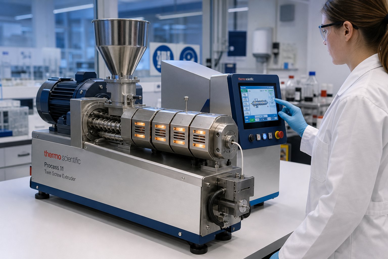
What Is a Lab Twin Screw Extruder and Who Needs One
Imagine spending weeks perfecting a polymer formulation on your twin screw extruder lab setup, only to discover that nothing translates when you move to a production-scale machine. It happens more often than most researchers admit. The root cause? A fundamental misunderstanding of what lab-scale extrusion equipment is designed to do, and where its responsibilities end. Before diving into the anatomy, configurations, and scale-up strategies that fill the rest of this guide, you need a crystal-clear picture of the machine itself and the people who rely on it.
Defining the Lab Twin Screw Extruder
A lab twin screw extruder is a compact, high-precision polymer processing machine featuring two co-rotating or counter-rotating screws with diameters typically ranging from 10 to 27 mm, engineered to deliver throughputs from just a few grams up to low single-digit kilograms per hour. Its core purpose is to enable repeatable, small-volume experimentation for formulation development, process optimization, and material characterization under tightly controlled conditions.
That definition matters because it highlights a critical distinction. A laboratory twin screw extruder is not simply a shrunken production line. Every subsystem, from the drive motor and feeding mechanism to the barrel architecture and control software, is purpose-built around research-grade precision and minimal material consumption. Production extruders prioritize throughput and uptime. Lab machines prioritize data quality and experimental flexibility.
Where a full-scale twin screw extruder might process hundreds or thousands of kilograms per hour, a lab extruder lets you run a valid compounding trial with as little as 500 grams of raw material. That difference is not just about size. It reshapes how you design experiments, how you interpret process data, and ultimately how successfully you transfer results to larger equipment.
Who Uses Lab-Scale Twin Screw Extruders and Why
Four major communities depend on these machines daily, each drawn by a slightly different value proposition:
- Academic polymer labs use a lab extruder to teach extrusion fundamentals, run thesis research, and explore novel material systems. The low material requirement means even expensive engineering resins and specialty additives stay within a graduate-student budget.
- Pharmaceutical hot-melt extrusion groups rely on lab-scale equipment for amorphous solid dispersion development, taste-masking studies, and continuous-manufacturing feasibility work. When active pharmaceutical ingredients cost thousands of dollars per kilogram, wasting material on a full-scale run is simply not an option.
- Food-science R&D teams process plant-based proteins, starches, and novel ingredients through lab twin screw extruders to study texturization, gelatinization, and flavor encapsulation at a fraction of the cost and time a pilot plant demands.
- Industrial pilot-line operators treat the laboratory extruder as a screening tool. They narrow dozens of candidate formulations down to three or four promising recipes before committing pilot-line hours, slashing material waste and accelerating time to market.
Across all four groups, the shared appeal boils down to three things: minimal material waste, rapid formulation iteration, and the ability to conduct controlled process-parameter studies that produce publishable, scalable data. You'll notice that none of these advantages have anything to do with making product in volume. That is entirely the point, and it is exactly where scale-up thinking needs to begin.
The sections ahead break down machine components, screw configurations, real-world research workflows, and the scale-up methodology that connects lab results to production reality. But every one of those topics rests on a foundational question most teams skip over too quickly: does your project actually call for a lab-scale machine, or would a different equipment tier serve you better?
Lab-Scale vs Pilot-Scale vs Production-Scale Extruders Compared
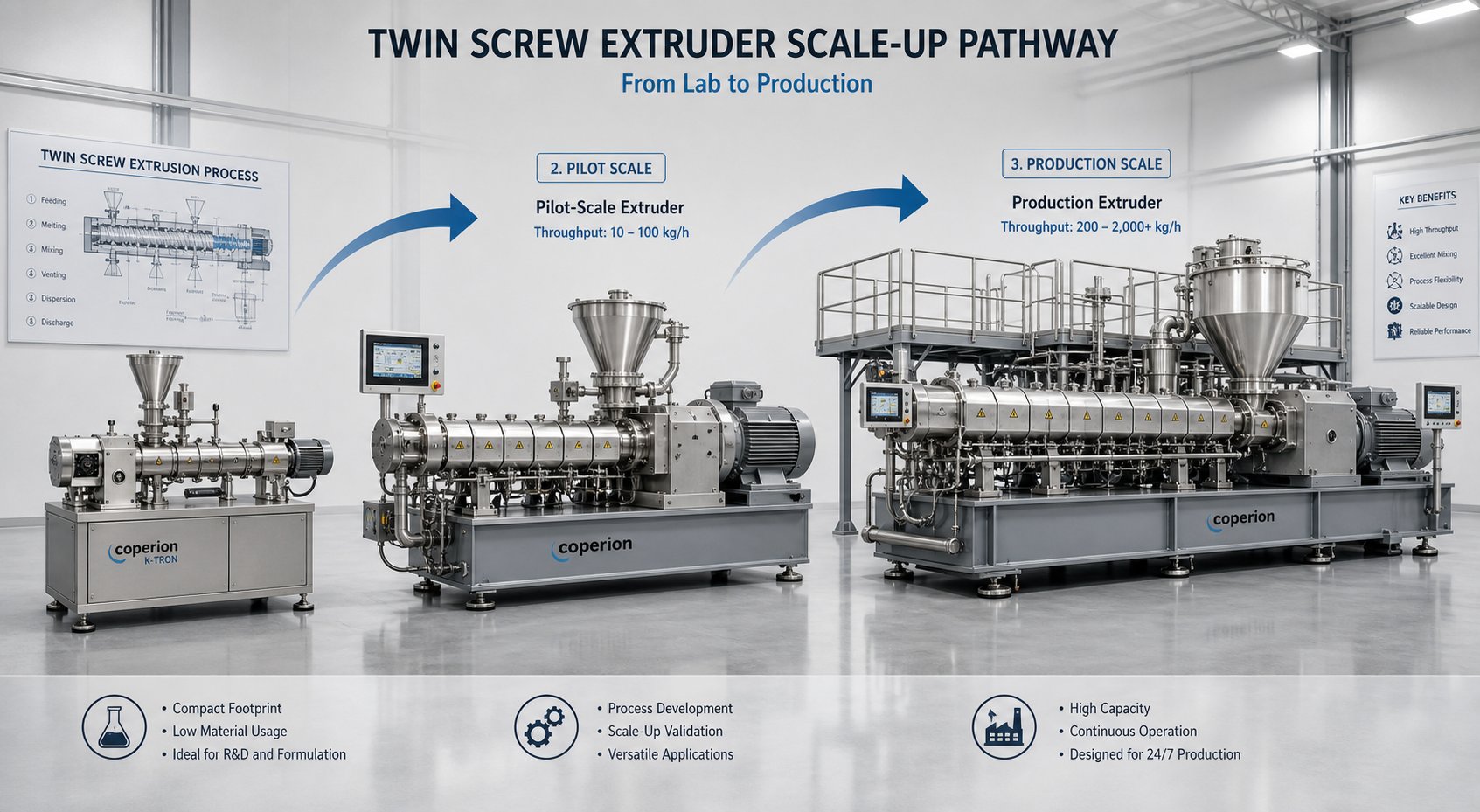
Choosing the wrong equipment tier burns through budgets, delays timelines, and produces data you cannot use downstream. A lab scale twin screw extruder, a pilot-line system, and a full production twin screw extruder machine are not interchangeable steps on the same ladder. Each tier occupies a distinct role in the development pipeline, and understanding where the boundaries fall prevents costly mismatches between your project scope and your hardware.
Key Parameters Across Equipment Scales
The table below maps the specifications that matter most when you are deciding which scale fits your current objectives. You will notice that differences extend well beyond screw diameter. Motor power, footprint, and batch-size flexibility all shift in ways that directly affect how you design experiments and interpret results.
| Parameter | Lab Scale | Pilot Scale | Production Scale |
|---|---|---|---|
| Screw Diameter Range | 10 – 27 mm | 24 – 50 mm | 50 – 200+ mm |
| Typical Throughput (kg/h) | 0.1 – 15 | 10 – 100 | 100 – 4,000+ |
| Motor Power Range | 0.5 – 7.5 kW | 7.5 – 55 kW | 55 – 800+ kW |
| Machine Footprint | Benchtop to ~3 m length | 3 – 6 m length | 6 – 15+ m length |
| Batch Size Flexibility | Grams to low kg; ideal for scarce materials | Moderate; requires several kg minimum | Low; startup waste alone can exceed 50 kg |
| Typical Cost Tier | Lowest | Moderate | Highest |
| Primary Use Case | Formulation screening, process-parameter studies, feasibility | Process validation, customer samples, scale-up data | Continuous commercial manufacturing |
A benchtop twin screw extruder at the smallest end of the lab-scale range, with screw diameters around 11 to 16 mm, can run meaningful compounding trials on as little as 200 grams of material. That flexibility is unmatched at any other scale. Pilot systems typically need a few kilograms just to establish steady-state conditions, and production machines consume far more during startup and transition runs alone.
When a Lab-Scale Machine Is the Right Choice
Four decision criteria consistently point toward a laboratory scale extruder rather than a larger system:
- Limited material availability. If your total supply of a novel resin, expensive additive, or early-phase pharmaceutical ingredient sits below 5 kg, a lab scale extruder is the only practical option for generating meaningful process data.
- Rapid recipe iteration. Running 10 to 20 formulation variants in a single day is routine on lab equipment, where changeover times between recipes can be as short as 15 to 30 minutes.
- Constrained floor space. Many research labs simply cannot accommodate a pilot-line footprint. A compact benchtop twin screw extruder fits into existing lab infrastructure without facility modifications.
- Budget sensitivity. When you need twin-screw mixing capability but your capital budget does not stretch to pilot-scale pricing, a lab machine delivers the core functionality at the lowest investment tier.
Equally important is recognizing when a lab twin screw extruder is not the right tool. If you are processing highly shear-sensitive materials, such as certain thermoplastic elastomers or long-fiber composites that degrade under intensive mixing, a batch internal mixer may preserve material integrity far better than any continuous extruder at small scale. Similarly, if your task involves straightforward melting and forming of a single polymer with no compounding or mixing demands, a single screw extruder is simpler, cheaper, and perfectly adequate. Forcing a twin-screw solution onto a problem that does not require distributive or dispersive mixing just adds complexity without adding value.
Picking the right scale is only half the equation. The internal architecture of the machine you select, starting with the drive system, feeding mechanisms, and segmented barrel design, determines what kind of data you can actually collect and how transferable that data will be when the project moves forward.
Core Components of a Lab Twin-Screw Extruder Explained
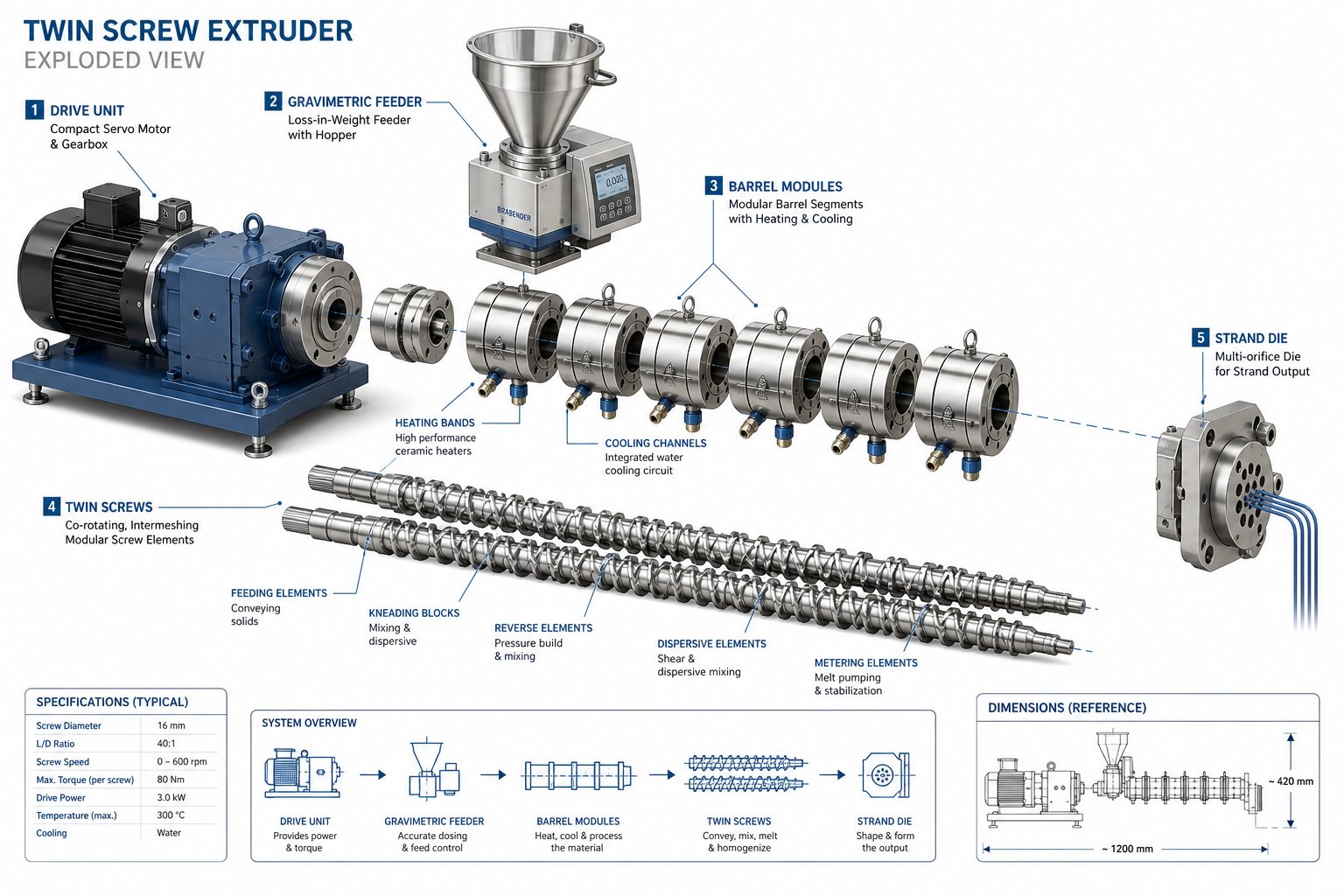
Every twin-screw extruder, regardless of size, shares the same basic anatomy: a drive system, a feeding mechanism, a segmented barrel, rotating screws, and a die. Strip away the surface similarities, though, and you'll find that a lab-scale machine handles each of these subsystems in fundamentally different ways than its production-scale counterpart. The constraints of small screw diameters, low throughputs, and tight research tolerances force engineering compromises and design choices that directly affect your experimental data. Understanding these differences is what separates researchers who generate scalable results from those who spend months troubleshooting problems that were built into their hardware from the start.
Drive System and Torque Considerations at Small Scale
Production extruders rely on massive AC motors delivering 55 kW or more. A lab-scale screw extruder, by contrast, uses compact servo or AC drives typically rated between 0.5 and 5 kW. That sounds like a straightforward size reduction, but the real story is about torque density, not raw power.
Why does torque density matter more here? Picture a 16 mm diameter screw trying to melt and mix a high-viscosity engineering resin. The tiny cross-sectional area of the shaft limits how much torque the gearbox can transmit before mechanical failure. Modern lab extruder systems address this with high-ratio gearboxes, often 15:1 or higher, that multiply motor torque while reducing screw speed to a usable range. The result is enough mechanical energy to plasticize demanding polymers without overshooting the shaft's structural limits.
Gearbox ratio also dictates the range of processable viscosities. A lab twin-screw extruder machine equipped with a high-torque, low-speed gearbox configuration handles stiff melts like polycarbonate or PEEK more effectively, while a lower-ratio setup favoring higher screw speeds suits lower-viscosity formulations and distributive mixing tasks. Selecting the wrong gearbox ratio for your target material family constrains your processing window before you even load the first batch of resin. As noted in research published in AAPS PharmSciTech, the torque transmitted to the shaft is often the limiting factor for the amount of power available to process materials on segmented-screw twin screw extruders, making this consideration especially acute at laboratory scale where shaft diameters are smallest.
Feeding Systems for Low-Rate Accuracy
Imagine trying to pour a precise, steady stream of powder at a rate of 100 grams per hour. That is roughly one gram every 36 seconds, and even a brief interruption creates a measurable spike in your process data. Feeding accuracy at lab-scale throughputs is one of the most underappreciated challenges in small-scale extrusion, and it can quietly undermine the validity of an entire experimental campaign.
Two feeder architectures dominate the landscape: volumetric and gravimetric. Volumetric feeders meter material by displacement, using a rotating auger or disc to push a set volume per revolution. They are simpler and less expensive, but their accuracy depends entirely on the bulk density of the feed material staying constant, something that rarely happens with powders or regrind. Gravimetric (loss-in-weight) feeders solve this by continuously weighing the hopper and adjusting the feed mechanism in real time to maintain a target mass flow rate. At lab scale, where throughputs may sit below 500 g/h, gravimetric control is critical for generating repeatable compounding data. Research from Plastics Technology highlights that when feeding below 150 g/h, even gravimetric control can struggle with longer weight-recording intervals, meaning your equipment supplier's testing program should validate performance at your specific target rate.
Beyond the main feed hopper, a well-equipped extruder system typically includes additional entry points along the barrel:
- Side-stuffing ports allow downstream addition of shear-sensitive fillers like glass fiber or carbon fiber directly into an already-molten polymer stream, bypassing the high-intensity melting zone and preserving fiber length.
- Liquid injection systems introduce plasticizers, reactive agents, or dissolved APIs through precision metering pumps at controlled downstream positions, enabling reactive extrusion and wet-granulation workflows.
Getting the feed system right is not glamorous work, but at low rates, a feeder inconsistency of even a few grams per minute can shift your additive concentration by several weight percent, turning a controlled experiment into a source of unexplained scatter.
Segmented Barrel Architecture and Die Options
If the screws are the heart of a twin-screw extruder, the barrel is the skeleton that gives the process its shape. Lab-scale machines use a modular barrel concept: individual segments, each typically 4 to 5 L/D in length, bolt together to form the full process section. Every segment can be independently heated and cooled, creating distinct thermal zones that researchers rearrange to match the demands of a given formulation.
This modularity is far more than a convenience feature. Swapping a closed barrel segment for one with a vent port enables vacuum devolatilization at a different position along the melt path. Replacing a standard segment with a side-feed barrel allows downstream filler addition. On a production barrel extruder, making these changes might require days of downtime and heavy-duty rigging. On a lab machine, a skilled operator can reconfigure the entire barrel in under an hour.
Typical lab-scale barrel configurations include:
- 6 to 10 individually controlled temperature zones
- L/D ratios ranging from 32:1 to 48:1, with 40:1 being the most common general-purpose setup
- Cartridge heaters with internal cooling bores for precise PID-controlled thermal management
- At least one vacuum vent port for moisture and volatile removal
At the discharge end, the die determines the shape of the extrudate and plays a direct role in pressure generation, melt temperature, and product quality. Lab machines support a range of interchangeable die configurations tailored to different research objectives:
- Strand dies produce round filaments that are water-cooled and pelletized, the most common setup for compounding studies
- Flat (slit) dies create thin films or sheets for transdermal patch development and barrier-property testing
- Annular dies form hollow tubes for medical tubing research and coextrusion studies
- Rod dies extrude solid cylindrical profiles for pharmaceutical implant prototyping
One detail worth flagging: die-head thermal mass has an outsized effect at lab scale. A die designed for a 60 mm production machine bolted onto a 16 mm lab extruder acts as a massive heat sink, distorting melt temperature and pressure readings. Purpose-built lab dies with minimal metal mass respond faster to temperature setpoint changes and produce data that more accurately reflects what is happening inside the barrel rather than inside the die itself.
With the physical hardware mapped out, the next logical question shifts from what the machine looks like to how the screws inside it actually rotate, because the choice between co-rotating and counter-rotating configurations reshapes everything from mixing intensity to residence-time distribution.
Co-Rotating vs Counter-Rotating Twin Screw Configurations
Rotation direction is not a minor spec-sheet detail. It fundamentally alters how material flows, how heat builds, and how thoroughly your formulation gets mixed. Two twin screws spinning in the same direction behave nothing like two spinning in opposite directions, and picking the wrong configuration for your research goal can produce misleading data that falls apart the moment you try to scale. Here is what each option actually does inside the barrel, and when to choose one over the other.
Co-Rotating Intermeshing Twin Screws
In a co rotating twin screw extruder, both screws turn in the same direction using a fully intermeshing geometry. Material gets forcibly handed from one screw flight to the next at the intermeshing zone, creating intense shear fields both between the screws and between each screw and the barrel wall. This produces the high distributive and dispersive mixing that makes co-rotating machines the dominant configuration in lab compounding and pharmaceutical extrusion.
The real power of co-rotating designs, though, lies in their modular screw element system. You are not locked into a single screw geometry. Instead, you build a custom screw profile by stacking individual elements onto a common splined shaft:
- Conveying elements with variable pitch control how quickly material advances and how much the channel fills. Large-pitch elements move material fast with low fill; small-pitch elements slow things down and increase fill level.
- Kneading blocks at stagger angles of 30 degrees, 45 degrees, 60 degrees, or 90 degrees deliver progressively more aggressive mixing. A 30-degree block provides minimal mixing with good forward conveyance, while a 90-degree neutral block generates maximum mixing with zero conveying capability.
- Reverse (left-handed) elements push material backward, building local pressure and increasing residence time upstream. They act as restrictive elements that force complete fill and drive melt seals for vacuum venting.
This modularity means you can redesign your screw profile between experiments in under an hour, tailoring the energy input and mixing intensity to each new formulation. The key advantages of co-rotating intermeshing twin screws include:
- Self-wiping action that suppresses stagnation, keeps dead zones minimal, and narrows residence-time distribution
- Excellent distributive and dispersive mixing in a single pass
- Wide processing window across a broad range of polymer viscosities
- High throughput relative to screw diameter compared to other configurations
For most lab-scale work involving polymer blends, nanocomposites, reactive extrusion, or hot-melt pharmaceutical formulations, co-rotating geometry is the default starting point.
Counter-Rotating and Conical Configurations
When you compare a co rotating and counter rotating twin screw extruder side by side, the differences go deeper than rotation direction. In a counter-rotating design, the two screws turn in opposite directions. Material gets drawn into the intermeshing region and compressed rather than sheared, producing a calendering effect that disperses additives under relatively gentle conditions. Shear stress and the resulting shear heating stay low, a critical advantage when processing thermally sensitive materials that degrade under the intense mixing a co-rotating machine delivers.
Counter-rotating machines come in two geometric sub-variants, each suited to different research scenarios:
A parallel twin screw extruder in counter-rotating mode maintains a constant screw diameter along its full length. This layout provides positive displacement conveying with a narrow residence-time distribution, making it well suited for processes where consistent thermal exposure matters, such as devolatilization-heavy applications or precise reactive extrusion with tight stoichiometric control.
A conical twin screw extruder features a tapered screw profile, larger at the feed end and smaller at the discharge end. That taper creates a natural compression zone that enhances pressure generation without relying on high screw speeds. Conical designs are a staple in PVC processing, where the combination of poor thermal stability and low melt flow demands low-temperature, high-pressure extrusion. In a lab context, conical machines serve researchers studying rigid PVC formulations, direct profile extrusion, or any material that benefits from strong pressure buildup combined with gentle thermal treatment.
Choosing a Configuration for Your Research Goals
So which configuration belongs in your lab? The answer maps directly to what you need the screws to do to your material:
| Research Goal | Recommended Configuration | Why It Fits |
|---|---|---|
| Polymer compounding and masterbatch development | Co-rotating intermeshing | High mixing intensity, modular screw design, self-wiping |
| Reactive extrusion (grafting, crosslinking, polymerization) | Co-rotating intermeshing | Narrow RTD, precise energy input control, excellent mass transfer |
| Pharmaceutical hot-melt extrusion | Co-rotating intermeshing | Dominant industry standard, wide processing window, data accepted by regulators |
| Rigid PVC formulation and profile extrusion | Counter-rotating conical or parallel | Low shear heating, strong pressure generation, gentle calendering effect |
| Shear-sensitive or thermally unstable materials | Counter-rotating parallel | Lower shear stress, minimal temperature rise, positive conveying |
| Devolatilization-focused studies | Counter-rotating parallel | High fill operation, consistent residence time, efficient vapor removal |
If you are running a general-purpose materials research lab and can only invest in one machine, a co rotating twin screw extruder covers the widest range of applications. Counter-rotating and conical machines earn their place when your research centers on a specific material class, like PVC or pressure-sensitive adhesives, where gentler processing is not optional but essential for meaningful results.
Configuration determines how energy enters your material. But the question of what you actually do with that energy, the specific research workflows that transform raw polymers into publishable data, is where lab-scale extrusion truly earns its keep.
Research Workflows That Demand Lab-Scale Twin Screw Extrusion
Saying a lab extruder is "used for R&D" is like saying a microscope is "used for looking at things." It is technically true and practically useless. The real value of twin screw extrusion at lab scale only becomes visible when you walk through the concrete, day-to-day workflows that researchers actually run, workflows where consuming minimal material, iterating fast, and logging precise process data are not just nice-to-haves but hard requirements for success.
Formulation Development and Additive Screening
Picture a polymer engineer tasked with developing a new glass-fiber-reinforced nylon compound for an automotive bracket. The target spec sheet lists stiffness, impact strength, heat deflection temperature, and warpage limits. Reaching all four simultaneously means balancing fiber loading, impact modifier type and concentration, nucleating agent level, and possibly a flow-enhancing additive. Even with just four variables at three levels each, that is 81 potential combinations.
Running all 81 on a production-scale compounding twin screw extruder would consume hundreds of kilograms of material and tie up a pilot line for weeks. A twin screw compounding extruder at lab scale flips that equation entirely. With throughputs as low as a few hundred grams per hour, you can screen 15 to 20 formulation variants in a single day, consuming only grams of each expensive additive.
The typical iterative workflow looks like this:
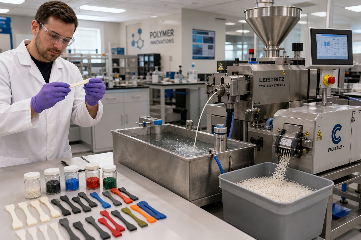
- Pre-blend polymer pellets and dry additives in a small tumble mixer.
- Compound the blend through the lab extruder at controlled barrel temperatures and screw speed.
- Pelletize the extrudate via a strand die and water bath or air-cooled strand cutter.
- Injection-mold test specimens (tensile bars, impact bars, flex bars) on a micro-molding machine.
- Characterize mechanical, thermal, and rheological properties against target specifications.
- Adjust the formulation based on results, and repeat from step one.
A skilled researcher can complete two full cycles of this loop in a single workday, generating enough data to eliminate weak candidates and zero in on two or three lead formulations for pilot-scale validation. That speed of iteration is the single biggest reason materials scientists reach for a lab-scale polymer extruder before anything else.
Pharmaceutical Hot-Melt Extrusion
In pharmaceutical development, the stakes for material efficiency are even higher. Active pharmaceutical ingredients (APIs) at the early clinical stage routinely cost several thousand dollars per kilogram, and total available supply may be measured in hundreds of grams. Wasting material on a poorly designed extrusion trial is not just expensive; it can delay an entire clinical program.
Lab twin screw extrusion has become a cornerstone technique for developing amorphous solid dispersions (ASDs), where a poorly soluble drug compound is molecularly dispersed in a polymeric carrier matrix to dramatically improve its bioavailability. A study published in AAPS PharmSciTech demonstrated the systematic development of an ASD from a 9 mm mini-extruder through to clinical-scale manufacturing, using as little as 5 to 20 grams of API per batch at the lab stage. The researchers screened multiple polymer carriers, identified a stable single-phase dispersion with PVP VA64, and achieved a fourfold improvement in bioavailability compared to the crystalline tablet formulation, all while consuming roughly 500 grams of total API across the entire development program.
Beyond ASDs, pharmaceutical scientists use lab-scale twin screw extrusion for:
- Taste masking of bitter APIs by encapsulating drug particles within a polymer or lipid matrix during the extrusion process
- Continuous manufacturing feasibility studies that establish process parameters transferable to GMP production lines
- Cocrystal formation through mechanochemical activation during extrusion, eliminating the need for solvent-based crystallization
The alignment is natural: small batch sizes match early-phase drug development timelines perfectly, and the continuous nature of the extruder for polymer or API-polymer blends produces more consistent dispersions than batch-based solvent evaporation methods. Regulatory agencies have grown increasingly comfortable with extrusion-based processes, further accelerating adoption across the pharmaceutical industry.
Specialty and Emerging Material Processing
Compounding and pharmaceutical work account for the largest share of lab-scale extrusion activity, but the technology's reach extends into several rapidly growing research domains. When processing novel or expensive material systems, the plastic twin screw extruder at lab scale offers the same core advantage it provides everywhere else: the ability to generate process understanding from minimal feedstock.
Consider bio-based polymer development. Researchers blending poly(lactic acid) with softer biodegradable polyesters to improve toughness use lab extruders to screen blend ratios and optimize screw configurations before committing to pilot-scale trials. A recent investigation into PLA/PBSe blends used Design of Experiments coupled with twin-screw extrusion simulation software to optimize temperature profiles, screw speeds, and feed rates, ultimately demonstrating that just 10 wt% of a bio-based polyester extruder compound delivered the highest fracture toughness improvement. That kind of systematic process-property mapping starts at the lab bench.
The breadth of specialty applications continues to expand. Ranked by general frequency of use across research institutions, the top application categories for lab-scale twin screw extrusion include:
- Polymer compounding and masterbatch development (filled, reinforced, and multi-component systems)
- Pharmaceutical hot-melt extrusion (ASDs, taste masking, implants)
- Bio-based and biodegradable polymer blending (PLA, PHA, PBS, and related systems)
- Nanocomposite preparation (clay, graphene, carbon nanotube dispersion)
- Reactive extrusion (grafting, crosslinking, chain extension, in-situ polymerization)
- Recycled-content compounding and upcycling studies
- Food-science applications (texturized plant protein, starch modification, flavor encapsulation)
- 3D printing filament development and specialty fiber extrusion
Each of these categories shares a common thread: researchers need to understand how process parameters influence material structure and performance, and they need to build that understanding quickly, affordably, and with enough rigor to support the next stage of development. A polyester extruder trial for biodegradable film research, a nanocomposite dispersion study for barrier packaging, or a reactive grafting experiment for compatibilizer synthesis all follow the same fundamental logic of iterating rapidly on small volumes before committing resources at scale.
Concrete workflows like these produce actionable data only when the equipment cooperates. In practice, lab-scale operation introduces a set of processing challenges, from feed-rate instability to disproportionate material waste, that production-scale operators rarely encounter and that most equipment manuals barely acknowledge.
Common Lab-Scale Processing Challenges and Practical Solutions
A production extruder can absorb a brief feed hiccup within the kilograms of melt already filling its barrel. A lab machine with just a few cubic centimeters of free volume? It exposes every disturbance immediately at the die. That difference is not just an inconvenience. It means the same physics governing full-scale screw extrusion gets amplified to a degree that can quietly invalidate your experimental data if you are not prepared for it. The challenges below rarely appear in equipment manuals, yet they account for the majority of frustrating trial days in any twin screw extruder lab.
Feed Rate Consistency at Low Throughputs
Sounds simple enough: pour powder into a hopper, let the feeder deliver it to the screws. At 500 grams per hour or above, it usually works. Drop below that threshold and you enter a regime where tiny disruptions cascade into dramatic output swings.
Three culprits dominate at low feed rates:
- Hopper bridging. Fine powders, hygroscopic granules, and highly filled premixes can arch over the feed throat of a 12 to 20 mm extruder, choking flow entirely. The arch collapses, floods the screw, reforms, and creates the classic surging strand. A production hopper with a 60 mm throat shrugs off these arches. A lab feed throat does not.
- Screw-feeder pulsing. Volumetric feeders meter by displacement, and at very low RPMs the intermittent motion of the auger introduces a periodic flow variation. Each revolution delivers a slug of material followed by a brief gap, and at lab-scale throughputs that pulsation translates directly into concentration swings in your extrudate.
- Electrostatic effects. Fine powders, particularly mineral fillers and some polymer dust, build static charges that cause particles to cling to hopper walls, feeder screws, and feed-throat surfaces. The material sticks, releases in clumps, sticks again, producing an erratic mass flow that no downstream control can correct.
Practical solutions exist for each of these, and combining several usually delivers the steadiest feed:
- Hopper agitators and vibrating trays. A small rotating paddle or vibratory tray mounted above the feed throat continuously breaks arches before they fully form. This is one of the most cost-effective upgrades for any lab-scale twin screw extrusion process.
- Micro-screw or disc-based gravimetric feeders. Gravimetric (loss-in-weight) feeders weigh the hopper continuously and adjust the feed mechanism in real time, removing bulk-density variability from the equation. At rates below 150 g/h, selecting a feeder with a high-resolution load cell and short weight-recording intervals becomes critical.
- Pre-blending strategies. Mixing fine additives with the main polymer pellets in a small tumble blender before feeding improves flowability and reduces segregation. Adding a trace of anti-static agent or grounding the hopper and feed tube addresses electrostatic cling directly.
One diagnostic worth remembering: if your output fluctuates but the hopper looks full, watch the screw intake directly. A feed throat that is not continuously filled confirms starvation regardless of hopper level. Establishing the maximum sustainable feed rate before raising screw speed prevents the most common route to unstable, air-laden output on a compounding extruder at lab scale.
Material Waste Minimization and Cleaning Protocols
On a production line, the 10 to 20 kilograms lost during startup and shutdown barely register against a multi-ton daily output. On a lab machine processing a total batch of 500 grams, that same proportional loss could consume your entire material supply before you collect a single usable sample. Waste management is not just a cost issue at lab scale; it is a feasibility issue.
Three strategies keep startup and shutdown waste to a minimum:
- Staged startup with inexpensive carrier resin. Bring the barrel to temperature and establish stable flow using a low-cost base polymer before switching to your experimental formulation. This purges residual air and old material from the barrel without consuming precious feedstock.
- Tight transition windows. Monitor the extrudate visually and with inline pressure readings. The moment the strand appearance and die pressure stabilize after switching to your target formulation, begin sample collection. Every second of delay wastes material that cannot be recovered.
- Downstream capture for screw extruder granulator systems. When running a pelletizing line, divert the initial off-spec strand to a separate collection bin rather than contaminating your sample lot. Label and weigh transition material separately so it does not skew your mass-balance calculations.
Cleaning between experiments deserves just as much discipline. Cross-contamination from a previous trial, even at trace levels, can shift additive concentrations, alter nucleation behavior, or introduce color artifacts that corrupt your data without any obvious visual warning. Three cleaning approaches cover the spectrum from routine changeover to deep decontamination:
- Purging compounds. Commercial purging resins contain chemical agents and mechanical scrubbing media designed to displace residual polymer from screw flights, barrel walls, and die channels. They outperform bare production resin for the same reason dish soap outperforms plain water on a greasy pan. Purging specialists at Plastics Technology emphasize that using your next production resin to purge is poor economics: you waste far more material and time achieving what a few hundred grams of dedicated compound handles in 15 minutes. For routine light-to-dark or same-family changeovers, purging is fast and sufficient.
- Barrel pull-apart and manual screw cleaning. For dark-to-light transitions, heat-sensitive resins, or any situation where purging alone leaves visible contamination, physically pulling the screws is necessary. Clean them while hot using brass brushes and brass scrapers exclusively. Steel tools scratch the nitrided screw surface, creating micro-craters where degraded polymer hides and re-carbonizes on every future run. Photograph the element order before disassembly so reassembly preserves the correct screw configuration and phase angle.
- Ultrasonic screw cleaning. For stubborn carbonized deposits in kneading-block grooves and tight element gaps, ultrasonic cleaning baths dissolve residue without any risk of mechanical damage to the screw surface. This method is particularly valuable in research environments that frequently switch between chemically incompatible polymer families.
Treat cleaning as part of your experimental protocol, not as an afterthought. A lab that logs its cleaning method alongside its process parameters catches contamination artifacts during data analysis rather than months later during peer review.
Temperature Control Precision and Dead Volume
A small barrel heats and cools quickly, which is convenient for changeovers but dangerous for stability. On a production machine, thick steel and large thermal mass damp temperature fluctuations naturally. On a lab extruder, a single faulty heater band or a drifting thermocouple changes local melt viscosity within seconds, and the screw immediately pumps differently. That responsiveness makes the lab machine a sensitive instrument, but it also means a 2-degree overshoot that would be invisible on a 90 mm barrel can meaningfully shift your data on a 16 mm machine.
Zone-by-zone PID tuning is essential. Lab barrels, with their low thermal mass, can be tuned tighter than production systems but still need adequate derivative damping to avoid sustained oscillation. Aggressive integral action after a setpoint change will overshoot, then ring around the target temperature, dragging melt viscosity and output with it. The approach recommended by process control engineers for first-order-plus-dead-time systems applies directly here: start conservative, verify that each zone settles without oscillation, and confirm stable melt temperature at the die after a full thermal soak before collecting any experimental data.
Die-head thermal mass adds a related complication. A die designed for larger equipment bolted onto a small lab barrel acts as a heat sink with its own slow thermal response. The melt temperature you read at the die may lag the actual barrel conditions by minutes, and bypass valve extrusion configurations or adapters between the barrel and die introduce additional dead volume where polymer stagnates, degrades, and eventually contaminates your sample stream.
Before every experimental run, work through this verification checklist to catch temperature-related problems before they reach your data:
- Confirm each zone thermocouple reads within 1 degree Celsius of a reference instrument, and verify the thermocouple is seated firmly in its well, not loosened or coated with burned polymer.
- Allow a full thermal soak of 15 to 30 minutes after all zones reach setpoint. Small barrels still need this equilibration time, and skipping it produces a warm-up transient that mimics instability.
- Check that cooling channels are flowing and that water or air supply pressure is stable. Variable cooling flow introduces a slow thermal drift that operators frequently mistake for a feed problem.
- Verify heater-band resistance against the manufacturer's specification. A band with a partially open element delivers uneven power and creates hot or cold spots along the barrel.
- Monitor actual melt temperature at the die, not just barrel-wall setpoints. Shear heating from the screw can push real melt temperature well above the barrel setting, especially at higher screw speeds, and that shear contribution varies with fill level.
- Review PID tuning parameters if you have switched to a material with significantly different thermal properties since the last calibration. A profile tuned for polyethylene will not control polycarbonate melt the same way.
- Inspect the die and any adapter sections for stagnant dead volume where degraded material can accumulate and periodically break free into the sample stream.
Many apparent instability complaints vanish entirely once the machine is given a proper thermal soak and each zone is verified against a calibration reference. The discipline of treating your lab extruder like a precision analytical instrument, calibrating its thermal systems with the same rigor you would apply to an analytical balance, is what separates clean, publishable process data from frustrating noise.
Reliable processing, however, depends on more than just solving day-to-day operational headaches. The digital controls that log every temperature, pressure, and torque reading, and the maintenance routines that keep the hardware performing to specification over months and years, form the infrastructure that makes sustained research productivity possible.
Digital Controls, Data Logging, and Maintenance Best Practices for Twin Screw Extruders
A perfectly tuned screw profile and an optimized temperature map mean nothing if your control system cannot reproduce them six months later, or if worn hardware silently degrades your data quality between calibration checks. Yet most discussions of lab-scale extrusion stop at the barrel flange and never address the digital infrastructure or physical upkeep that make sustained research productivity possible. These two topics, controls and maintenance, are where long-term equipment value is either preserved or quietly destroyed.
Digital Controls, Data Logging, and Recipe Management
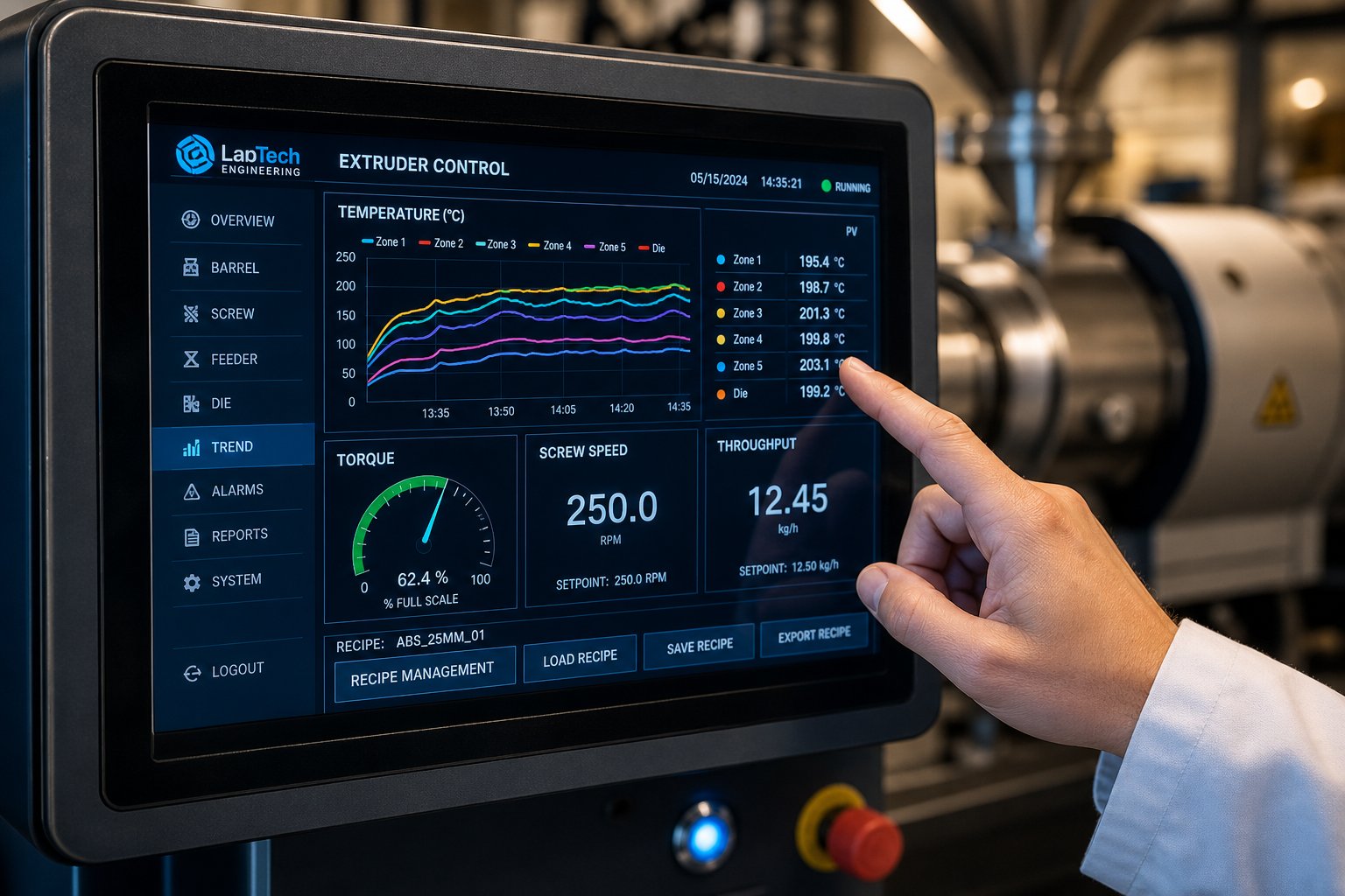
Walk up to any modern lab-scale twin screw extruder and you will find a touchscreen human-machine interface (HMI) rather than the analog dials and strip-chart recorders that dominated earlier generations. That shift is not cosmetic. The HMI serves as the operational nerve center, giving you real-time visibility into every critical process variable: barrel zone temperatures, screw speed, motor torque percentage, die pressure, melt temperature, and feed rate. You set parameters, monitor trends, and receive instant alarms when any reading drifts outside a user-defined tolerance band.
But real-time display is only the starting point. The feature that transforms a lab extruder from a processing tool into a research instrument is automatic data logging. Every parameter the HMI displays gets time-stamped and recorded at intervals as tight as one second, creating a complete digital fingerprint of each experimental run. Why does this matter so much?
Imagine you run a promising formulation today, publish the results in eight months, and then a reviewer or collaborator asks you to replicate the experiment. Without a comprehensive data log, you are relying on handwritten notes and memory to reconstruct the exact barrel temperatures, screw speed ramp profile, torque curve during startup, and feed-rate fluctuations that produced your original sample. With logged data, you pull up the archived file, overlay the old and new runs on the same time axis, and verify replication within seconds. Research reproducibility lives or dies in this gap.
Recipe management builds on the same principle. A recipe stores every setpoint, barrel zone temperature, screw speed, feeder calibration, and alarm limit associated with a specific experimental condition. You name it, save it, and recall it before any future run. For experimental campaigns that span weeks or months, recipe management eliminates the drift that creeps in when operators manually re-enter dozens of parameters from a lab notebook. It also accelerates screening campaigns: switching from formulation A to formulation B becomes a two-tap operation on the HMI, cutting changeover dead time and keeping your throughput of experimental data high.
Modern twin-screw extruders designed for research environments take integration a step further. Many systems now export logged data directly to laboratory information management systems (LIMS) through standard communication protocols like OPC-UA or simple CSV file transfers. This seamless data archiving means your extrusion process records sit alongside DSC scans, tensile test results, and rheology curves in a single searchable database. For pharmaceutical labs operating under FDA 21 CFR Part 11 requirements, electronic record integrity and access controls are not optional; they are regulatory prerequisites that the control system must enforce through user authentication, audit trails, and tamper-evident data storage.
One practical tip worth emphasizing: configure your data logging to capture torque as a percentage of the machine's maximum rated torque, not just as an absolute motor current reading. Torque percentage is a normalized metric that travels with you across equipment scales, making it far more useful for scale-up comparisons than raw amperage, which changes with every motor size. Similarly, log specific energy input (kWh/kg) automatically whenever possible. This single number encapsulates the combined effects of screw speed, feed rate, and material viscosity into a dimensionless parameter that directly supports process transfer to larger screw extruders down the road.
Maintenance Best Practices for Longevity
A lab extruder processes far less material per year than a production machine, so it is tempting to treat maintenance as a low priority. That instinct is wrong. The precision tolerances that make lab-scale data meaningful are also the first things to degrade when maintenance lapses. A 16 mm screw with 0.15 mm overflight clearance loses mixing efficiency faster, proportionally, from the same absolute amount of wear than a 90 mm screw with 0.6 mm clearance. Small machines punish neglect disproportionately.
Routine maintenance falls into four categories: inspection, monitoring, lubrication, and calibration. Each operates on its own schedule, and stacking them into a structured program prevents the reactive "fix it when it breaks" pattern that causes unplanned downtime and corrupts experimental data without warning.
- After each run:
- Purge the barrel thoroughly or pull screws for cleaning, depending on the next material to be processed. Never leave polymer solidified in the barrel overnight; thermal cycling on the next startup will degrade and carbonize it.
- Inspect die faces and screen packs for blockage or wear marks.
- Wipe down barrel exteriors and check for any polymer leaks at barrel-to-barrel joints or at the die clamp.
- Verify that all vent ports are clear and that vacuum seals are intact if devolatilization was used.
- Weekly:
- Inspect screw elements visually for wear on kneading block tips and flight lands. Look for scoring, galling, or discoloration that indicates metal-to-metal contact.
- Check the torque reading at idle (screws turning with no feed). A steady rise in no-load torque over time indicates bearing wear in the gearbox or increased drag from worn barrel liners.
- Confirm that all cooling water or air lines are flowing at their rated pressure and volume.
- Monthly:
- Calibrate temperature sensors against a traceable reference. A thermocouple drifting by even 3 degrees Celsius alters melt viscosity enough to shift your process window.
- Verify pressure transducer zero and span. Die-pressure readings that drift upward without any process change often indicate a fouled transducer diaphragm rather than a real pressure rise.
- Lubricate the gearbox according to the manufacturer's oil type and fill-level specification. Synthetic gear oils are standard on modern twin-screw extruders and should be checked for discoloration or metallic particle contamination, both early indicators of internal wear.
- Inspect feeder calibration by running a timed collection of feed output and comparing the actual mass to the setpoint. Recalibrate if deviation exceeds 2 percent.
- Annually:
- Perform a complete barrel bore measurement using precision bore gauges. Compare results to the manufacturer's original bore diameter. Bore enlargement beyond 0.1 mm on a lab-scale machine warrants barrel liner replacement or reconditioning.
- Measure screw element outside diameters with a micrometer and compare against new-part specifications. Worn elements reduce mixing intensity and increase leakage flow, both of which silently alter your process data.
- Service the gearbox: drain and replace oil, inspect gear teeth and bearings, and verify that the overtorque protection coupling engages at its specified threshold.
- Revalidate the entire control system, including HMI alarm setpoints, data logging integrity, and recipe storage accuracy, against the documented system specification.
Tracking torque-limit trends deserves special emphasis. The Plastics Industry Association reports that roughly 60 percent of twin screw extruder failures trace back to improper maintenance of screw and barrel components. On a lab machine, where the entire investment hinges on data quality, catching a wear trend early through monthly torque-at-idle logging is far cheaper than discovering degraded mixing performance buried in three months of experimental scatter.
Extending Equipment Lifespan
Beyond the scheduled maintenance calendar, three operational habits have an outsized impact on how long your twin-screw extruders stay within specification.
Proper startup and shutdown sequencing is the single most impactful habit. A cold start with solidified polymer in the barrel forces the drive system to shear through a rigid plug, generating extreme torque spikes that stress shafts, gearbox teeth, and screw elements simultaneously. The correct procedure, as outlined in industry-standard startup protocols, is straightforward: heat all barrel zones to their setpoints, allow a 15 to 30 minute thermal soak until temperatures stabilize, and only then start the screws at low RPM before introducing feed material gradually. At shutdown, the sequence reverses: stop the feeder first, allow the screws to pump the barrel empty, then stop screw rotation while the barrel is still hot. If the next run uses a different material, purge with a compatible cleaning compound before shutdown so the barrel cools with clean surfaces rather than a degrading residual melt.
Never leave screws sitting in a hot, empty barrel. Residual oxygen at elevated temperature accelerates surface oxidation on nitrided steel, pitting the flight lands and roughening the very surfaces that need to stay smooth for effective self-wiping and tight clearance control. If the machine will sit idle for more than a day, pull the screws, clean them while warm, and apply a light film of anti-corrosion oil or food-grade grease before storing them in a protective tray. This 20-minute investment after shutdown prevents weeks of troubleshooting mysterious discoloration and adhesion problems in future runs.
Store spare screw elements and barrel liners properly. Precision-ground screw elements stored loosely in a drawer bang against each other, chipping hardened edges and damaging the spline bore. Use the original packaging or a compartmented tray, keep elements lightly oiled, and store them in a low-humidity environment. The same applies to replacement barrel inserts: surface corrosion from improper storage means your "new" spare part starts its service life already compromised.
These habits sound basic, and they are. But in the daily pressure of running experiments, basic steps get skipped. Researchers who build startup checks, shutdown protocols, and post-run cleaning into their standard operating procedures, treating them as non-negotiable steps rather than optional housekeeping, consistently get longer service life, tighter data, and fewer surprise repair bills from their lab equipment.
Operational discipline keeps your machine running to spec. But the materials the screws and barrels are made from determine what "spec" means in the first place, and at lab scale, metallurgy choices influence data quality and equipment longevity in ways most researchers never consider until wear damage forces the conversation.
Screw and Barrel Metallurgy for Lab-Scale Applications
Your screw configuration might be perfectly optimized, your temperature profile dialed in to the degree, and your feed rate rock-steady. None of that matters if the metal your twin screw and barrel are made from cannot handle the material you are processing. Metallurgy is the silent variable that determines whether your lab extruder delivers consistent data for 10,000 hours or starts producing questionable results after 2,000. At production scale, premature wear shows up as declining output and rising energy costs. At lab scale, it shows up as something far more insidious: gradual erosion of the dimensional precision your experiments depend on, often without any visible warning until your data no longer reproduces.
Despite how directly metallurgy affects research quality, most twin screw extruder lab users select screw and barrel materials based on whatever ships as standard from the equipment manufacturer. That default choice works fine for unfilled commodity polymers. The moment you introduce glass fibers, mineral fillers, halogenated flame retardants, or reactive chemistries, the conversation changes entirely.
Metallurgy Options for Lab Screws and Barrels
The metallurgy landscape for twin screw barrel components spans five distinct tiers, each engineered around a specific balance of hardness, toughness, corrosion resistance, and cost. Understanding where each tier fits prevents both the expensive mistake of over-specifying soft polymer work and the destructive mistake of under-specifying abrasive or corrosive formulations.
| Material Class | Hardness Range | Best Suited For | Relative Cost | Typical Lab Application |
|---|---|---|---|---|
| Custom-Designed Alloy Solutions | Application-dependent | Non-standard material systems, novel research compounds, multi-mechanism wear environments | Variable | University research with exotic polymers, proprietary formulation work, specialized pilot studies |
| Nitrided Tool Steels (4140, 4340) | 55 – 62 HRC surface | Unfilled commodity polymers, low-abrasion blending | Lowest | General-purpose compounding of PE, PP, PS, ABS without fillers |
| Through-Hardened Tool Steels (D2, M2) | 58 – 62 HRC | Moderate abrasive fillers, reinforced engineering resins at low loading | Moderate | Glass-filled nylon at 10 – 20% loading, mineral-filled masterbatch screening |
| Powder-Metallurgy Alloys (CPM 9V, CPM 10V) | 60 – 64 HRC | Severely abrasive fillers at high loading, glass fiber above 30% | High | High-loading mineral or glass-fiber composite development, ceramic-filled compound research |
| Corrosion-Resistant Alloys (Stellite, Hastelloy, Ni-based liners) | 35 – 52 HRC | Reactive polymers, halogenated compounds, fluoropolymers | Highest | PVC formulation studies, PVDF processing, halogenated flame-retardant compounding |
Each tier addresses a different dominant wear mechanism. Nitrided steels rely on a shallow hardened case, typically 0.3 to 0.7 mm deep with surface hardness around 950 to 1,100 HV, that works well against mild abrasion but wears through quickly under aggressive filler contact. Once that nitrided layer is gone, the softer substrate beneath erodes rapidly, a failure mode that composites processing experts describe as cutting through "like a hot knife through butter." You will not see it coming unless you pull and inspect the screws regularly.
Through-hardened D2 delivers four to six times the abrasion resistance of nitrided 4140, making it the practical step-up for researchers who routinely process moderately filled compounds. The hardness extends through the full cross-section rather than sitting in a thin case, so wear progresses linearly instead of catastrophically.
Powder-metallurgy grades like CPM 10V represent the step change above conventional tool steels. Their uniform vanadium carbide distribution, with individual particles reaching approximately 2,500 HV, outperforms D2 by three to five times in standardized ASTM G99 pin-on-disk abrasion testing. For a lab processing 40 to 60 percent mineral-filled formulations, CPM-grade twin screw elements routinely exceed 20,000 hours of service, compared to 3,000 to 4,500 hours for nitrided alternatives.
Corrosion-resistant alloys occupy a different axis entirely. When processing PVC, PVDC, or fluoropolymers, hydrogen chloride or hydrogen fluoride gas evolves at processing temperatures, creating a chemical environment that corrodes even hardened tool steels at measurable rates. Nickel-based alloys and cobalt-chromium overlays like Stellite form passive films that resist this attack, delivering corrosive wear rates eight to twelve times lower than nitrided steel in chlorinated polymer service.
Matching Screw Design to Research Materials
Here is where many lab teams make a critical error: they select metallurgy and screw element geometry as independent decisions. In practice, the two are inseparable.
Consider a researcher developing a 30 percent glass-fiber-reinforced polyamide compound on an extruder twin screw setup. The screw profile needs aggressive kneading blocks, likely 60-degree stagger angles, to achieve adequate fiber wetting and dispersion. Those kneading blocks concentrate shear energy at their tips, exactly where metal-to-filler contact is most intense. Install those same kneading elements in standard nitrided steel, and you will observe measurable tip wear within a few hundred hours of processing. The worn tips reduce mixing intensity, alter residence-time distribution, and progressively degrade the quality of your compounding data without triggering any alarm on the control system.
Flip the scenario. A team blending unfilled PLA with a biodegradable polyester for packaging film research does not need CPM 10V kneading blocks. The material is not abrasive, the processing temperatures are moderate, and the cost premium of powder-metallurgy alloys adds zero value. Standard nitrided elements handle this application for years without measurable wear. Specifying premium metallurgy here wastes budget that could fund additional experiments.
The decision matrix boils down to matching the dominant wear mechanism to the metallurgy tier that addresses it:
- Abrasion-dominated (glass fiber, minerals, ceramics): Through-hardened D2 minimum; CPM 10V for loadings above 25 to 30 percent by weight.
- Corrosion-dominated (PVC, halogenated FR, fluoropolymers): Stellite overlay on screw flights, nickel-alloy bimetallic barrel liners. Hardness alone will not protect against chemical attack.
- Combined abrasion and corrosion (glass-filled PVC, mineral-filled halogenated compounds): WC-CrC-Ni thermal spray or Stellite-plus-WC composite systems that address both mechanisms simultaneously.
- Minimal wear (unfilled or lightly filled commodity and bio-based polymers): Standard nitrided steel, with the cost savings redirected toward screw element variety for configuration studies.
Specialized labs and university research groups working with exotic material systems often find that no off-the-shelf twin screw barrel and element combination matches their specific needs. A team processing experimental ceramic-loaded polymers at unusual L/D ratios, or running reactive extrusion with corrosive byproducts at non-standard barrel configurations, may need elements that simply do not exist in any equipment manufacturer's standard catalog. In these situations, working with a provider that offers custom screw and barrel design services, such as those available from NANHAIYA, gives researchers a practical pathway to obtain screw geometries and metallurgy combinations tailored to their specific research materials and compact lab equipment. Rather than compromising on a close-enough standard element that introduces avoidable wear or suboptimal mixing, a custom-designed twin screw configuration aligns the hardware precisely to the experimental requirements.
This is especially relevant for groups whose work spans multiple material families. A single lab extruder might process abrasive glass-fiber compounds one week and corrosive halogenated formulations the next. Having access to multiple screw element sets, each specified with the correct metallurgy for its intended material class, protects both the equipment and the integrity of the data. Any reputable twin-screw extruder manufacturer will tell you that a one-size-fits-all screw set is a compromise that works acceptably for some applications and poorly for others. The research environments that produce the most reliable, scalable data are the ones that treat metallurgy selection as a first-order experimental design decision, not an afterthought left to the purchasing department.
Metallurgy determines how long your hardware holds its precision. But even the best-specified twin screw and barrel combination only solves half the scale-up puzzle. The methodology you use to transfer lab-generated process data to larger equipment, where shear rates, heat transfer, and residence times all shift non-linearly, is where most scale-up projects succeed or fail.
Scale-Up Methodology from Lab Bench to Production Line
Here is the uncomfortable truth most twin screw extruder lab teams discover too late: a formulation that runs beautifully on a 16 mm machine can fall apart spectacularly on a 92 mm production line. Not because the chemistry changed, but because the physics of extrusion does not scale the way intuition suggests. Doubling the screw diameter does not simply double the throughput. It reshapes shear rate distributions, rewrites heat transfer ratios, and stretches residence times in ways that can transform a stable, homogeneous melt into an unprocessable mess. Understanding why this happens, and designing your lab experiments to anticipate it, is the difference between a smooth technology transfer and months of expensive troubleshooting on a double screw extruder machine you cannot afford to tie up.
Principles of Geometric and Process Scale-Up
Three dominant scale-up approaches exist, and each preserves a different aspect of the material's experience inside the barrel:
- Geometric similarity. Maintain the same L/D ratio, OD/ID ratio, and screw element sequence from lab to production. This ensures that the relative proportions of conveying, mixing, and pressure-building zones stay constant across scales. A case study published in Plastics Technology used geometrically similar co-rotating extruders at 26 mm, 40 mm, and 92 mm diameters, all sharing an L/D of 44 and an OD/ID ratio of 1.55, as the foundation for systematic scale-up of a polyolefin masterbatch.
- Volumetric scale-up. Match specific throughput per unit free volume. When a process is power/volume-limited rather than heat-transfer-limited, the maximum throughput scales with the cube of the diameter ratio (Dtarget/Dactual)3. When heat transfer through the barrel wall is the bottleneck, it scales with the square of that ratio instead. Choosing the wrong exponent leads to either underfeeding, which wastes capacity, or overfeeding, which starves the material of energy.
- Energy-input matching. Preserve specific mechanical energy (SME), expressed in kWh/kg. SME captures the total mechanical work the screws deliver per kilogram of material and directly influences dispersion quality, melt homogeneity, and amorphous stability in pharmaceutical dispersions. As Thermo Fisher Scientific notes, maintaining comparable SME across scales is not optional; it is essential for preserving product performance.
Why can't you simply run a bigger double screw extruder at the same RPM and temperature profile? Because the area-to-volume ratio of the barrel drops dramatically as diameter increases. A 26 mm extruder has far more barrel surface area per unit melt volume than a 92 mm machine, meaning it can exchange heat with the melt far more effectively. At larger diameters, external barrel heating and cooling become less influential, and the process becomes increasingly adiabatic, driven primarily by the mechanical energy of the screws rather than the thermal environment of the barrel walls.
The Dow case study illustrates this vividly. Researchers optimized a masterbatch process on a 26 mm lab extruder, achieving an SME of 0.083 kWh/kg. Directly transferring those same operating conditions to the 40 mm pilot machine produced severe pressure fluctuations and visible phase separation, with SME dropping to just 0.055 kWh/kg, a 34 percent shortfall. Adjustments to screw design, temperature profile, and screw speed brought SME back to 0.079 kWh/kg and restored process stability. The jump to 92 mm was even more dramatic: initial SME plummeted to 0.026 kWh/kg, a 69 percent drop from the lab reference, resulting in solid polymer pellets discharging unmolten through the diverter valve. Only after a root-cause analysis and redesign of the screw configuration and feeding arrangement did SME recover to 0.086 kWh/kg, finally enabling stable, homogeneous production at a rate 12.17 times the 40 mm throughput.
The pattern is clear. Residence time, shear rate distribution, and heat transfer all change non-linearly with diameter. Treating scale-up as a simple multiplier exercise virtually guarantees process failure at some point along the path from lab bench to production floor.
Designing Lab Experiments with Scale-Up in Mind
The twin screw extruders market continues to expand as more industries adopt continuous processing, and with that growth comes increasing pressure to move formulations from lab to production faster. Yet the single biggest accelerator of that transition is not a faster machine or a bigger budget. It is the quality of the data you generate at the lab stage.
Successful scale-up begins with intentional experimental design at the lab bench, not reverse-engineering after the fact.
What does intentional design look like in practice? It means building your experimental campaign around the parameters that actually transfer across scales, rather than collecting data that is only meaningful on your specific lab machine. Here are the recommendations that experienced scale-up engineers consistently emphasize:
- Record every process parameter meticulously. Barrel zone temperatures, screw speed, motor torque (as a percentage of maximum), die pressure, melt temperature, and feed rate should be logged automatically at one-second intervals minimum. You will need this granularity to calculate SME, identify transient instabilities, and build a defensible process history.
- Use dimensionless numbers. Specific throughput (Q/N, where Q is mass flow and N is screw speed), fill fraction, and SME travel across equipment scales far more reliably than absolute RPM or kg/h values. When you report that your optimized process runs at a specific throughput of 0.035 kg/h/rpm, a scale-up engineer can immediately estimate the corresponding feed rate on a larger machine at any target screw speed.
- Build a process map, not a single operating point. Run your formulation across multiple combinations of screw speed and feed rate, not just one "optimized" condition. Mapping torque, melt temperature, and die pressure across a matrix of at least three feed rates and three screw speeds reveals the boundaries of your processing window. Those boundaries shift during scale-up, and knowing the shape of your window on the lab machine tells you which direction to adjust on the larger one.
- Select screw configurations with scale-up geometry available. Before finalizing your lab screw profile, verify that equivalent element geometries, same stagger angles, same L/D per element, same conveying pitch ratios, exist in the catalog for the target production diameter. A novel screw profile that produces excellent lab results but cannot be replicated at 50 or 70 mm creates a dead end.
- Monitor residence time distribution (RTD) when possible. Even a simple tracer-pulse experiment using a colored masterbatch gives you a baseline RTD curve. Comparing lab and pilot RTD curves during scale-up trials immediately reveals whether the material is spending more or less time under thermal and mechanical stress at the larger scale.
Researchers evaluating a twin screw extruder for sale often focus on screw diameter and throughput specs while overlooking whether the machine's control system supports the data-logging depth and recipe management required for rigorous scale-up documentation. Similarly, twin screw extruder price comparisons rarely account for the downstream cost of poor data: a machine that saves 15 percent on purchase price but lacks automatic SME calculation or high-resolution torque logging can add months to a technology transfer timeline. The most valuable lab extruder is the one that generates data clean enough to survive the transition to a machine ten times its size.
Bridging the Gap with Custom Screw Configurations
One of the most frustrating scale-up bottlenecks has nothing to do with process physics. It is a catalog problem. You spend weeks perfecting a lab screw configuration using a specific sequence of conveying elements, kneading blocks at particular stagger angles, and reverse elements at precise positions along the barrel. Then you try to replicate that exact configuration at 50 mm or 70 mm and discover that the element catalog for the larger machine does not include the same geometries. The pitch ratios differ, the kneading block widths are not proportional, or the reverse element lengths do not match. Your carefully validated screw profile cannot be faithfully reproduced, and the scale-up loses its geometric anchor before the first pellet of resin enters the hopper.
This gap is more common than it should be. Different twin screw extruder manufacturers design their element catalogs independently, with no obligation to maintain geometric proportionality across diameter ranges. Even within a single manufacturer's lineup, lab-scale and production-scale element libraries sometimes evolved at different times and reflect different design philosophies. The result is that a screw profile optimized on a 16 mm lab machine may not have a direct geometric equivalent at 40 mm or 62 mm.
Custom screw design services exist specifically to close this gap. Providers like NANHAIYA work with R&D labs, pilot-line operators, and universities to design matched screw geometries across scales, ensuring that the element sequence validated at the lab bench translates faithfully to pilot and production diameters. Rather than forcing a compromise with whatever standard elements happen to be available, custom-designed elements preserve the specific pitch ratios, kneading block proportions, and flight geometries that defined your lab-scale processing window.
This capability is particularly valuable for teams whose research spans the full development pipeline. If your lab data will eventually support a twin screw extruder price justification for production equipment, the credibility of that data depends on demonstrating that the process can be geometrically replicated at scale. A custom screw set designed in parallel with your lab optimization ensures that the scale-up path exists before you commit to it, not after your production trials reveal that it does not.
The rapidly expanding twin screw extruders market means more organizations are navigating this lab-to-production transition than ever before. Whether your application is polymer compounding, pharmaceutical hot-melt extrusion, or food-science texturization, the methodology remains the same: preserve geometric similarity, match SME, design experiments around dimensionless parameters, and verify that your screw configuration has a scalable counterpart. The teams that embed these principles into their workflow from day one do not just avoid scale-up failures. They reach production qualification months ahead of those who treat scale-up as a problem to solve after the lab work is finished.
Frequently Asked Questions About Twin Screw Extruder Lab Setups
1. What screw diameter and throughput range defines a lab twin screw extruder?
Lab twin screw extruders typically feature screw diameters between 10 and 27 mm and deliver throughputs ranging from a few grams to low single-digit kilograms per hour. This compact scale allows researchers to run valid compounding or formulation trials with as little as 200 to 500 grams of raw material, making them ideal for expensive polymers, early-phase pharmaceutical ingredients, and novel additive screening where material conservation is critical.
2. How do you choose between co-rotating and counter-rotating twin screw configurations for lab research?
Co-rotating intermeshing screws are the default choice for most lab work, including polymer compounding, reactive extrusion, and pharmaceutical hot-melt extrusion, because they deliver high distributive and dispersive mixing with self-wiping action. Counter-rotating configurations, whether parallel or conical, are preferred for thermally sensitive materials like PVC, pressure-sensitive formulations, and devolatilization-heavy applications where lower shear stress and gentler calendering action preserve material integrity.
3. Why do lab-scale extrusion results often fail during production scale-up?
Scale-up failures occur because shear rate distributions, heat transfer ratios, and residence times change non-linearly as screw diameter increases. A larger barrel has a lower surface-area-to-volume ratio, reducing the effectiveness of external heating and cooling and shifting the process toward adiabatic conditions. Maintaining specific mechanical energy (SME in kWh/kg) across scales, using dimensionless parameters like specific throughput (Q/N), and ensuring geometric similarity in screw element sequences are essential strategies. Teams that skip these steps and simply replicate RPM and temperature setpoints on larger machines almost always encounter process instability.
4. What screw and barrel metallurgy should I select for abrasive or corrosive materials in a lab extruder?
For abrasive materials such as glass-fiber or mineral-filled compounds, through-hardened tool steels like D2 provide a baseline, while powder-metallurgy alloys like CPM 10V offer three to five times greater wear resistance for filler loadings above 25 to 30 percent. For corrosive formulations involving PVC, fluoropolymers, or halogenated flame retardants, nickel-based alloys or Stellite overlays resist chemical attack far better than hardened steels. When standard catalog options do not match your specific research materials, custom screw and barrel design services from providers like NANHAIYA (https://www.nhyscrews.com/services/custom-screw-design) can deliver tailored metallurgy and geometry combinations.
5. How do you minimize material waste and cross-contamination on a lab twin screw extruder?
Start each run with an inexpensive carrier resin to purge residual material and establish steady-state conditions before switching to your experimental formulation. Divert the initial off-spec extrudate to a separate bin and begin sample collection only after strand appearance and die pressure stabilize. Between experiments, use dedicated purging compounds for routine changeovers, pull and manually clean screws with brass tools for dark-to-light transitions, and employ ultrasonic baths for stubborn carbonized deposits. Logging your cleaning method alongside process parameters helps detect contamination artifacts during data analysis.
Written by
Nanhaiya Technical Team
Zhoushan Nanhaiya Plastic Machinery Co., Ltd.
The Nanhaiya technical team supports screw and barrel manufacturing projects through application review, technical communication, custom manufacturing coordination, and production and quality control.
Discuss Your Application
Related Articles
More insights on screw barrel technology and plastics processing.

What Nobody Tells You About Screw Barrel For Plastic Machine Design
Oct 10, 2026
Learn how screw barrel for plastic machine design affects melt quality, throughput, and wear life. Covers geometry, resin matching, troubleshooting, and sourcing.
Read Article
Single Screw Extruder for Sheet: Stop Guessing, Start Specifying
Oct 9, 2026
Learn how to specify a single screw extruder for sheet production. Covers screw geometry, resin-specific processing, troubleshooting, and maintenance best practices.
Read Article
PE Pipe Extruder Machine: What Datasheets Won't Tell You
Oct 9, 2026
Learn how a PE pipe extruder machine works, key specs explained, material grade selection, maintenance tips, and buyer guidance beyond the datasheet.
Read ArticleLooking for something else?
Search by material, symptom or product and jump straight to the relevant page.
These are navigation suggestions based on keyword matching — not a quotation, not a delivery commitment, and not a substitute for engineering review. Final specification is confirmed by our engineers against your drawings and processed material.
Need help with screw barrel selection?
Share your machine model, processed material and application. Our team can help with pricing and technical support.