

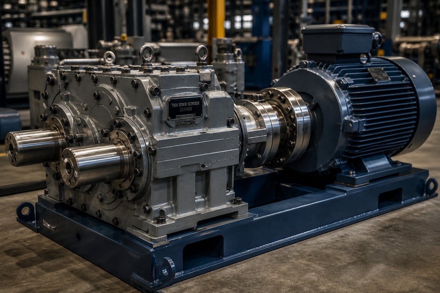
Understanding Twin Screw Extruder Gearboxes and Motors
Imagine spending six figures on a twin screw extruder drive system, only to discover it bottlenecks your entire production line within the first year. It happens more often than most engineers would like to admit. A retrofit case study documented by Tanhon revealed that an undersized gearbox allowed only 58% of motor power to actually reach the screw — turning an expensive motor into an underperforming asset. The root cause? A fundamental misunderstanding of how twin screw extruder gearboxes and motors function as a single, interdependent system.
A twin screw extruder gearbox converts high-speed motor output into the high-torque, low-speed synchronized rotation required by intermeshing twin screws, while absorbing significant axial thrust loads generated during extrusion.
That definition sounds straightforward, but the engineering reality behind it is anything but simple. The drive system — motor, coupling, gearbox, and screws — forms an integrated power transmission chain where every component's performance directly affects the others. Misunderstand one link, and you compromise the entire chain.
What the Drive System Actually Does
Think of the drive system as the heart and circulatory system of your extrusion line. The motor generates rotational energy at high speed and relatively low torque — typically between 960 and 1,480 RPM depending on pole count. Your twin screws, however, need something very different: high torque at low speed, usually between 15 and 600 RPM depending on extruder size and application. The gearbox bridges that gap. It reduces speed, multiplies torque, distributes power evenly to two synchronized output shafts, and absorbs axial thrust forces that can range from 2.5 kN on small lab machines to over 3,400 kN on large production units. No standard industrial gearbox handles all of those tasks simultaneously — this is a purpose-built machine.
Why Gearbox and Motor Knowledge Matters for Extrusion Professionals
Here is the problem: most product pages and catalogs treat the gearbox and motor as separate purchasing decisions. Engineers spec the motor for power. Procurement buys the gearbox on price. Maintenance inherits whatever arrives on the shop floor. This siloed approach is exactly how misspecification happens. Whether you are designing a new compounding line, replacing a worn-out drive, or troubleshooting chronic failures, you need to understand how screw geometry drives torque demands, how motor speed curves interact with gearbox reduction ratios, and why torque density matters more than catalog price.
This article takes a vendor-neutral, engineering-education approach to fill those gaps. You will find structured comparisons of gearbox architecture types, a practical guide to motor selection and sizing, breakdowns of critical specifications, application-specific selection criteria, common failure modes with preventive maintenance strategies, and a framework for evaluating suppliers. Each section builds on the last, giving you the complete picture that no single product page provides.
The logical starting point is the drivetrain itself — how power actually flows from motor shaft to screw tip, and why each stage in that chain shapes everything downstream.
How the Twin Screw Extruder Power Transmission Chain Works Together
Most gearbox spec sheets and motor catalogs describe their respective products in isolation — as if each component exists in a vacuum. In practice, every element in the twin screw extruder power transmission chain is mechanically coupled to the ones before and after it. A decision made at the motor affects the gearbox. A constraint inside the gearbox dictates what screw diameters you can run. And the screw geometry itself feeds back into the torque and thrust demands that the motor and gearbox must satisfy. Ignoring any link in this chain is where misspecification begins.
The Complete Power Transmission Chain
Picture the energy transformation as a five-stage relay. Raw electrical energy enters the motor and exits as synchronized mechanical rotation at the screw tips. Here is how each stage contributes:
- Electric Motor: Converts electrical energy into high-speed rotational energy. A typical AC induction motor delivers output between 960 and 1,480 RPM at relatively modest torque levels. This is the system's power source, and its rated speed directly determines the gearbox reduction ratio required downstream.
- Coupling: Connects the motor output shaft to the gearbox input shaft. Gear couplings or flexible disc couplings are most common here. The coupling serves a protective role — it accommodates minor shaft misalignment between motor and gearbox, dampens torsional vibration, and in some designs acts as a mechanical fuse that fails before more expensive components do. Underestimate the coupling, and you transmit damaging vibration straight into your gear train.
- Gearbox (Gear Stages): Reduces the high input speed to the low output speed the screws require, while multiplying torque in inverse proportion. The fundamental relationship is simple: Power (kW) = Torque (Nm) x Speed (RPM) / 9,550. At constant power, halving the speed doubles the torque. A gearbox with a 30:1 ratio reduces speed by 30x and multiplies torque by roughly 30x, minus small efficiency losses of 1 to 2% per gear stage.
- Output Shafts: Deliver synchronized rotation to both screws. In co-rotating twin screw designs, the gearbox must produce identical-direction rotation on two parallel shafts from a single input — a mechanically complex task requiring synchronization gears that maintain exact phase relationships between the shafts.
- Screw Elements: Convert the gearbox's mechanical output into the process work of conveying, melting, mixing, and pressurizing material. The screws push polymer melt forward toward the die, and Newton's third law pushes right back — generating the axial thrust force that travels through the output shafts directly into the gearbox's thrust bearing assembly.
Every stage in this sequence constrains the ones around it. You cannot select a motor without knowing the gearbox ratio, and you cannot determine the ratio without knowing your target screw speed.
Three Simultaneous Mechanical Tasks of the Gearbox
Here is what makes an extruder gearbox fundamentally different from a standard industrial reducer. Most gearboxes in conveyors, pumps, or fans handle speed reduction and torque multiplication — two tasks. A twin screw extruder gearbox must handle three simultaneously:
- Speed Reduction: Bringing motor output down from roughly 1,000-1,500 RPM to the 15-600 RPM range the screws require, distributed across two or three helical gear stages.
- Torque Multiplication: As speed drops through each gear stage, torque climbs proportionally. The output stage wheel gear — the largest gear in the gearbox — rotates slowest and delivers the highest torque. It must withstand continuous bending loads at the tooth root under forces that would destroy gears designed for lighter-duty applications.
- Axial Thrust Absorption: As material pressurizes against the die, the resulting back-pressure pushes each screw rearward toward the gearbox. This axial thrust can exceed 500 kilonewtons in large extruders processing rigid PVC or HDPE at high throughput. The gearbox's thrust bearing assembly — typically spherical roller thrust bearings or paired tapered roller bearings — must absorb this force continuously without transmitting it back to the motor bearings. Thrust bearing fatigue often limits gearbox life before the gear train itself shows wear.
That third task — axial thrust absorption — is the one most often underestimated during specification. It does not appear in standard gearbox catalogs because standard gearboxes are not designed for it. Yet it is frequently the failure mode that takes a production line down.
How Screw Geometry Drives Gearbox and Motor Requirements
The relationship between screws and drive system runs in both directions. The gearbox center distance — the fixed spacing between the two output shafts — physically constrains the maximum outer diameter of the screws you can install. You cannot fit a larger screw into a gearbox that was not designed for it. This single geometric parameter quietly limits your maximum throughput potential.
Screw geometry, in turn, feeds directly back into what the gearbox and motor must deliver. Two ratios matter most:
- L/D Ratio (Length-to-Diameter): Standard twin screw extruders use L/D ratios between 20:1 and 48:1. Longer screws improve plasticization and mixing but demand proportionally more torque. As Leistritz notes, a torque-limited process is one where there is simply not enough power from the motor to turn the screws and pump material through the process section and die system.
- Do/Di Ratio (Outer-to-Inner Screw Diameter): This ratio determines the free volume available inside the extruder at a given screw diameter. A higher Do/Di ratio — such as the 1.66 used in some modern designs versus a traditional 1.55 — provides greater free volume and higher throughput capacity, but it also changes the torque demand profile the gearbox must accommodate.
Increasing screw diameter follows a cube-law relationship with torque: doubling the screw diameter roughly octuples the torque requirement. That means a seemingly modest jump in screw size can demand a dramatically larger gearbox and motor package. Engineers who size the drive system based only on steady-state conditions — without accounting for cold-start torque spikes that can exceed running torque by 20 to 40% — often discover the hard way that their gearbox is the weakest link in the chain.
With the power transmission chain mapped out, the next critical question becomes which gearbox architecture best handles these simultaneous demands — and the answer varies significantly depending on whether you need a helical, planetary, or integrated design.
Twin Screw Extruder Gearbox Architecture Types Compared
Not every gearbox handles those three simultaneous demands — speed reduction, torque multiplication, and axial thrust absorption — in the same way. The internal architecture of a twin screw extruder gearbox determines how efficiently it converts motor power into usable screw torque, how compact it can be for a given torque capacity, and ultimately how long it lasts under continuous production loads. Yet most buyers evaluate gearboxes by a single number on a spec sheet without understanding the engineering trade-offs baked into each design. Four primary architectures dominate the market, and choosing among them is one of the most consequential decisions in specifying twin screw extruder gearboxes and motors.
Helical and Bevel-Helical Gearbox Designs
The helical gear train is the traditional workhorse of extruder drive systems. It uses two or three stages of parallel-shaft helical gears, each stage reducing speed and multiplying torque progressively. You will find this architecture on the majority of installed twin screw extruders worldwide. Its strengths are simplicity, proven reliability, and relatively straightforward maintenance — gear replacements and bearing swaps follow well-established procedures. The trade-off is size. Achieving high torque density with helical stages alone requires physically large gear wheels and wide face widths, which means a bigger, heavier gearbox housing.
Bevel-helical combinations add a right-angle bevel gear stage at the input, redirecting the motor axis by 90 degrees before the helical reduction stages take over. This layout is useful when plant floor constraints or machine frame geometry require the motor to mount perpendicular to the extruder barrel rather than inline. The bevel stage introduces a modest efficiency penalty — typically 1 to 2% beyond what the helical stages alone would lose — and the bevel gear teeth experience sliding contact that demands careful lubrication. In practice, bevel-helical designs serve niche layout requirements rather than offering a performance advantage over pure helical trains.
Planetary and Integrated Planetary Architectures
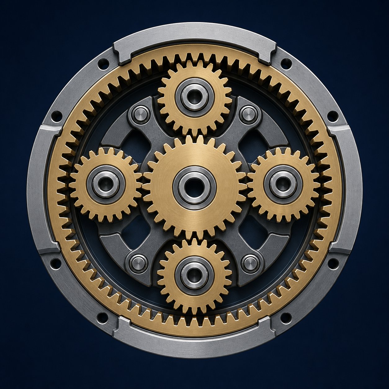
When torque density becomes the priority — packing maximum torque capacity into the smallest possible envelope — planetary gear stages change the equation entirely. In a planetary arrangement, multiple planet gears share the load simultaneously around a central sun gear, distributing forces across several tooth contacts instead of just one. This load-sharing effect delivers significantly higher torque density (measured in Nm/cm³) compared to a helical stage of equivalent size. As industry data shows, modern high-performance twin screw extruders now reach torque densities of 18 Nm/cm³ — a threshold that pure helical architectures struggle to achieve without becoming prohibitively large.
Integrated planetary designs push this concept further by combining a planetary input stage with parallel helical output stages — or stacking multiple planetary stages — to maximize torque per unit volume. These hybrid architectures are increasingly common on high-torque compounding lines processing glass-filled polyamides, mineral-filled polypropylene, and other abrasive, high-viscosity materials. The complexity and cost are higher, but for applications where the gearbox must deliver 15+ Nm/cm³ in a constrained machine footprint, integrated planetary designs are often the only viable option.
| Architecture Type | Torque Density | Compactness | Typical Applications | Complexity | Relative Cost |
|---|---|---|---|---|---|
| Helical (Multi-Stage) | Moderate | Low — larger housing required | General-purpose extrusion, profile lines | Low | $ |
| Bevel-Helical | Moderate | Moderate — allows motor reorientation | Space-constrained layouts requiring 90° motor offset | Moderate | $$ |
| Planetary | High | High — load shared across planet gears | High-torque compounding, reactive extrusion | High | $$$ |
| Integrated Planetary | Very High (15-18+ Nm/cm³) | Very High — maximum torque per unit volume | High-fill compounding, large-throughput production lines | Very High | $$$$ |
Co-Rotating Versus Counter-Rotating Configurations
Beyond internal gear architecture, the gearbox must also be designed around a fundamental process choice: do the two screws rotate in the same direction or in opposite directions? This distinction profoundly shapes gearbox complexity.
In a co-rotating configuration — by far the most common for compounding, reactive extrusion, and devolatilization — both output shafts must turn in the same direction from a single motor input. Sounds simple, but mechanically it is not. The gearbox needs synchronization gears that split a single input rotation into two identical-direction, phase-locked outputs at precisely the same speed. Any timing error, even a fraction of a degree under load, causes the intermeshing screws to collide. The gearbox absorbs the resulting shock loads, and repeated interference events destroy both the gear teeth and the screws. This synchronization requirement is a major reason why co-rotating gearboxes command higher prices and demand tighter manufacturing tolerances than their counter-rotating counterparts.
Counter-rotating gearboxes, by contrast, deliver opposite-direction rotation on the two output shafts — a mechanically simpler task since a single gear mesh naturally reverses direction. Counter-rotating twin screw extruders excel at processing thermally sensitive materials like rigid PVC, where lower shear stress and reduced heat generation are critical. The gearbox design for these machines is generally less complex, but the output shafts still must maintain precise speed synchronization to prevent screw interference in intermeshing designs.
There is also a third geometric variant worth noting: the conical twin screw extruder gearbox design. In conical machines, the two screws taper from a large diameter at the feed end to a small diameter at the discharge end. The axes of the two screws are not parallel — they converge at an angle. This geometry gives the gearbox a larger center distance at the drive end, which provides more room for robust thrust bearings and larger gear shafts. The result is higher axial load capacity and simpler bearing arrangements compared to a parallel twin screw gearbox of similar output. However, conical designs sacrifice the L/D ratio flexibility that parallel configurations offer, making them best suited for specific applications like PVC pipe and profile extrusion rather than general-purpose compounding.
Architecture type sets the mechanical boundaries of what a gearbox can deliver — but it is the motor driving that gearbox that determines how much power is actually available. Selecting the wrong motor type, or sizing it incorrectly for the torque curve your process demands, undermines even the best gearbox design.
Motor Types and Selection Criteria for Twin Screw Extruders
A perfectly specified gearbox still underperforms if the motor feeding it delivers the wrong speed curve, insufficient torque at low RPM, or poor efficiency under partial load. Yet motor selection for twin screw extrusion receives surprisingly little engineering attention — many plants simply reorder whatever motor type was originally installed, without questioning whether newer technology or a different sizing approach would better serve their process. This is the single largest content gap across the entire SERP for twin screw extruder gearboxes and motors, and it deserves a thorough, practical breakdown.
AC Induction, DC, and Permanent Magnet Motor Options
Three motor technologies dominate the installed base of twin screw extruder drive systems. Each brings a distinct set of trade-offs in performance, maintenance burden, and total cost of ownership.
AC induction motors with variable frequency drives (VFDs) are the industry standard for new installations. Their rugged rotor construction — no brushes, no commutator, no permanent magnets to demagnetize — makes them exceptionally reliable in the harsh thermal environment near an extruder barrel. Pair an AC induction motor with a modern VFD, and you get precise speed control across a wide range, soft-start capability that limits inrush current, and the ability to shape the torque curve to match your process. Maintenance is largely limited to bearing replacement and occasional insulation checks. For most compounding, devolatilization, and reactive extrusion applications, this combination offers the best balance of robustness, controllability, and cost.
DC motors still power a significant share of older extrusion lines. They offered excellent speed control long before affordable VFDs existed, which explains their historical dominance. The problem is mechanical complexity: carbon brushes and commutators wear, generate conductive dust, and require periodic replacement. Brush maintenance alone can account for several unplanned downtime events per year on a heavily utilized line. DC drive electronics are also becoming harder to source as manufacturers shift focus to AC platforms. If your plant runs legacy DC-driven extruders, they likely still perform adequately — but when the motor or drive reaches end of life, replacing with an AC induction motor and VFD almost always makes more economic sense than sourcing another DC system.
Permanent magnet synchronous motors (PMSM) represent the emerging high-performance option. By embedding rare-earth magnets directly into the rotor, a PMSM eliminates rotor copper losses entirely — the single largest source of inefficiency in an induction motor. The result is higher torque density in a smaller frame, better efficiency across the entire speed range (especially at partial loads), and reduced heat generation. For extruder applications where floor space is constrained or where energy costs dominate operating budgets, a permanent magnet motor for extruder applications can cut energy consumption by 5 to 15% compared to an equivalent IE3-rated induction motor. The trade-off? Higher upfront cost, a requirement for matched servo-grade drives, and the need for careful handling during installation to avoid damage to the magnets. PMSM adoption is accelerating in Europe and parts of Asia, though AC induction motors still account for the majority of new installations globally.
Motor Sizing Principles for Twin Screw Extrusion
Choosing between motor types is only half the equation. Sizing the motor correctly — selecting the right power rating, speed, and torque characteristics — determines whether your drive system actually delivers the throughput and process flexibility your line requires.
The fundamental sizing approach starts with three inputs: your target throughput (kg/h), the specific energy consumption of your material (kWh/kg), and the screw speed range needed for your process. The basic relationship is straightforward:
Required Motor Power (kW) = Target Throughput (kg/h) x Specific Energy Consumption (kWh/kg)
Specific energy values vary widely by material and process. Industry data shows typical ranges of 0.15 to 0.35 kWh/kg for unfilled polyolefins, 0.25 to 0.50 kWh/kg for color masterbatch production, and 0.4 to 0.8+ kWh/kg for highly filled compounds with glass fiber or mineral additives. A color masterbatch line targeting 500 kg/h at 0.8 kWh/kg, for example, would require approximately 400 kW of motor power — placing it firmly in the large production-scale category.
Here is where many engineers get tripped up: they size the motor for steady-state running conditions and forget about transient demands. Startup with cold material in the barrel can spike torque 20 to 40% above running levels. Material changeovers, gel slugs in recycled feedstock, and sudden feed rate changes all create momentary overloads. A 10 to 20% safety margin above calculated steady-state power is standard practice to accommodate these peaks without tripping the drive or stalling the screws.
Equally important is the relationship between motor base speed and the constant-torque versus constant-power operating regions. Below base speed — typically 1,200 to 1,500 RPM for a four-pole or two-pole motor — the VFD maintains constant torque output as speed decreases. Above base speed, the motor enters a field-weakening region where torque drops as speed rises, but power remains roughly constant. Why does this matter for extrusion? If your process requires high torque at low screw speeds (think high-viscosity reactive extrusion), you need a motor and gearbox ratio combination that keeps the motor operating in its constant-torque region during those conditions. Sizing only for maximum speed and relying on field-weakening to reach higher RPMs sacrifices torque precisely when your process may need it most.
The key motor selection parameters every engineer should evaluate and document before contacting suppliers include:
- Rated power (kW): Must exceed calculated steady-state requirement plus safety margin for transient loads.
- Rated speed (RPM): Determines gearbox reduction ratio; must align with target screw speed range through the gearbox ratio.
- Torque curve characteristics: Constant-torque range below base speed, constant-power range above — match these to your process speed and load profile.
- Efficiency class (IE3/IE4): Higher classes reduce operating cost; IE4 super-premium motors now deliver measurable payback on continuous-duty extruder applications.
- Cooling method: Totally enclosed fan-cooled (TEFC) is standard; forced ventilation or liquid cooling may be necessary at very low operating speeds where self-cooling diminishes.
- Enclosure rating: IP55 is typical for general compounding environments; food, pharmaceutical, or hazardous-area applications may require IP65 or explosion-proof ratings.
Energy Efficiency Trends in Extruder Motor Technology
Energy costs represent 30 to 50% of total operating costs in many extrusion operations, which makes motor efficiency far more than an environmental talking point — it is a direct lever on profitability. Two trends are reshaping how plants approach extruder motor efficiency.
The first is the shift toward IE4 super-premium efficiency motors. Regulatory pressure in the EU and parts of Asia is phasing out lower-efficiency motors for certain power ranges and duty cycles. Beyond compliance, the economics are compelling: an IE4 energy efficient extruder motor running continuously on a 200 kW compounding line can save $7,500 to $12,500 annually compared to an older IE2 motor at typical industrial electricity rates. Over a 15 to 20-year motor lifespan, that savings dwarfs the modest price premium at purchase.
The second trend is regenerative drive technology. Standard VFDs dissipate braking energy as heat through resistor banks when the motor decelerates. Regenerative drives feed that energy back into the plant electrical grid instead. On twin screw extruder lines with frequent speed changes — especially during product changeovers or batch processes — regenerative systems recover meaningful energy. They also reduce cooling loads in the drive cabinet, extending power electronics lifespan. The payback period depends heavily on how often the drive decelerates and local energy prices, but for high-utilization lines, it typically falls within two to four years.
Combining a PMSM with a regenerative drive represents the current state of the art in extruder motor efficiency. Whether that combination makes economic sense for your specific line depends on utilization rates, energy costs, and how much of your operating budget goes to electricity versus raw materials. The key takeaway for any twin screw extruder motor selection guide is this: motor choice is not just a capital expense decision — it is an ongoing operating cost decision that compounds over the life of the equipment.
Motor type and sizing define how much power enters the gearbox, but the specifications stamped on the gearbox nameplate determine how effectively that power reaches the screws. Understanding what those numbers actually mean — torque density, center distance, speed range — separates informed buyers from those who discover specification gaps only after commissioning.
Key Gearbox Specifications for Twin Screw Extruders Every Buyer Should Understand
Gearbox spec sheets can feel like alphabet soup — Nm/cm³, kN, RPM ranges, center distances in millimeters — all listed without much explanation of why those numbers matter or how they relate to each other. The problem is not that engineers lack access to specifications. The problem is that most spec sheets present each parameter as an isolated data point, when in reality every number on that nameplate is connected to every other one through hard physics. Learning how to read twin screw extruder gearbox specs as an interdependent system, rather than a checklist of independent values, is what separates confident specification from expensive guesswork.
Torque Density and Specific Torque Explained
If there is one specification that captures the engineering sophistication of a gearbox in a single number, it is torque density — measured in Nm/cm³. This figure expresses how much output torque the gearbox can transmit relative to its center distance (specifically, relative to the cube of the center distance). A higher torque density means the gearbox packs more torque capacity into a smaller physical envelope.
Why does that matter practically? Because a gearbox with higher twin screw extruder gearbox torque density allows you to either run more demanding materials within the same machine footprint, or achieve the same torque output with a lighter, more compact unit. As industry analysis confirms, torque density has become one of the most important indicators of gearbox design performance — particularly for modern applications processing engineering plastics, battery electrode slurries, and highly filled compounds that demand substantially more shear force than commodity polymers.
Torque density values have climbed steadily over the past two decades. Earlier-generation gearboxes typically delivered around 10 Nm/cm³. Mid-range modern designs reach 13 to 15 Nm/cm³. The current high-performance benchmark sits at 17 to 18 Nm/cm³, achieved through integrated planetary architectures and advanced bearing systems. These are not trivial differences — moving from 10 to 18 Nm/cm³ nearly doubles the usable torque for a given gearbox size, which translates directly into higher throughput capacity or the ability to process tougher formulations without upsizing the entire machine.
Closely related is specific torque per shaft, typically expressed in Nm per individual output shaft. While torque density describes the gearbox's efficiency as a design, specific torque per shaft tells you the practical reality: how much work each screw can actually perform. In a twin screw system, total gearbox output torque is split between two shafts — so a gearbox rated at 20,000 Nm total delivers 10,000 Nm per shaft. This per-shaft figure must exceed the maximum torque your screw geometry and process conditions will demand, including transient overloads during startup or material changes.
Center Distance, Speed Range, and Power Ratings
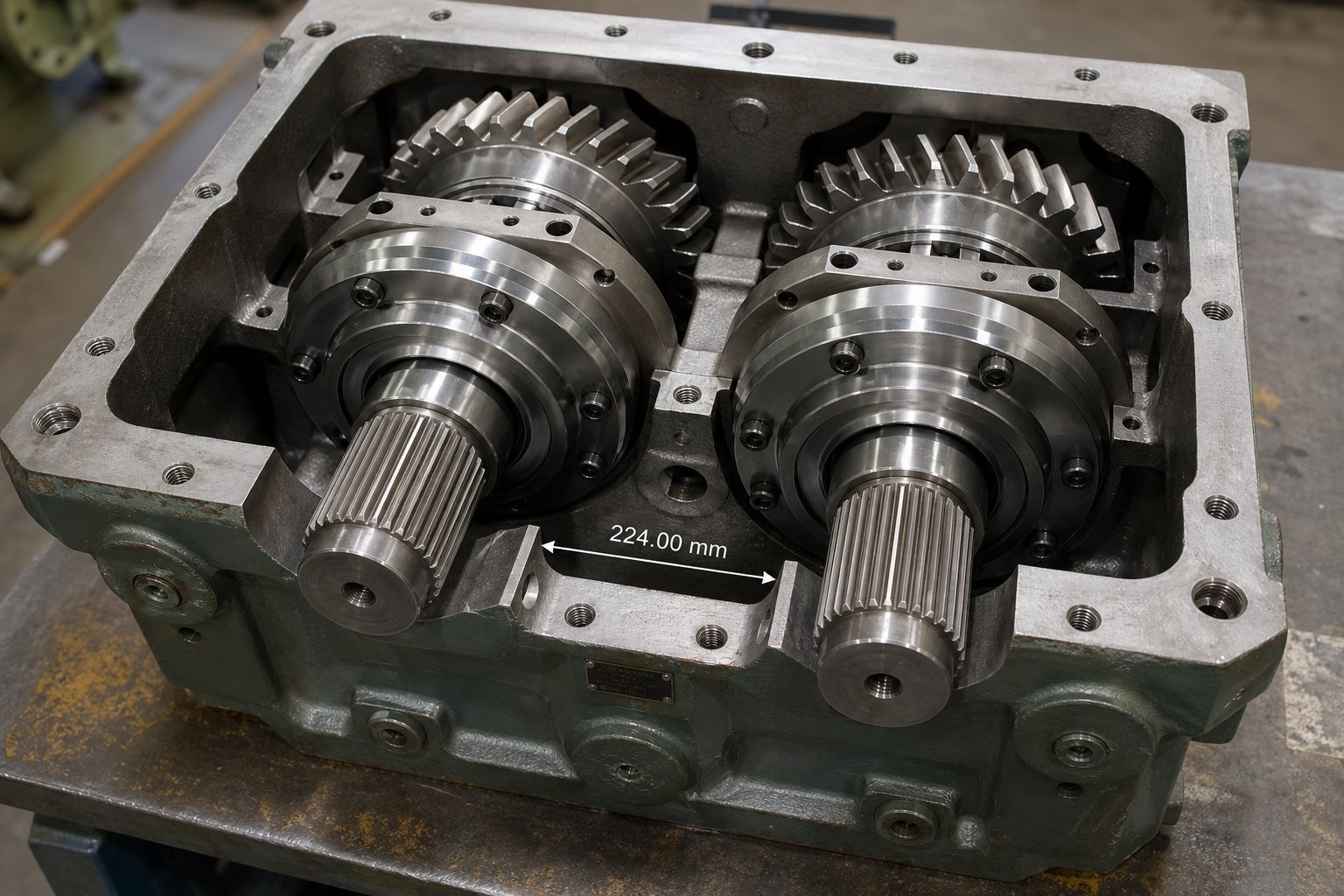
Center distance is arguably the most constraining geometric specification on any twin screw extruder gearbox — and yet it is frequently overlooked during early-stage specification. It defines the fixed distance between the centerlines of the two output shafts, and this single dimension determines the maximum outer diameter of the screws you can install. You cannot increase screw diameter beyond what the extruder gearbox center distance and screw diameter relationship allows. That means center distance quietly caps your maximum throughput potential before you ever consider torque or motor power.
Typical center distances range from around 18 to 21 mm on small laboratory extruders, through 30 to 70 mm on pilot and medium machines, up to 100 to 200+ mm on large production-scale compounding lines. Increasing center distance opens the door to larger screws with greater free volume and higher material throughput — but it simultaneously demands proportionally greater torque capacity from the gearbox and higher power from the motor. This is not a linear relationship. As discussed earlier, torque demand scales roughly with the cube of screw diameter, so a modest bump in center distance triggers a disproportionate escalation in drive system requirements.
Speed range specifications define the input and output RPM windows the gearbox can handle. Input speed is dictated by the motor — typically 960 to 1,500 RPM for standard AC motors. Output speed, after gear reduction, usually falls between 15 and 600+ RPM depending on extruder size and application. Smaller lab units often operate at the higher end of this range, while large production extruders may need lower screw speeds with correspondingly higher torque. The gearbox ratio bridges the gap: a 10:1 ratio converts 1,500 RPM input into 150 RPM output, while a 40:1 ratio brings it down to 37.5 RPM.
Power rating ties torque and speed together through the fundamental formula:
Power (kW) = Torque (Nm) x Speed (RPM) / 9,550
This relationship is non-negotiable physics. A gearbox rated for 500 kW at a specific output speed has a fixed maximum torque it can deliver at that speed. If you reduce the output speed — say, to process a higher-viscosity material — available torque increases, but only within the gearbox's mechanical limits. If you push the motor to deliver more power than the gearbox's rated input power can accept, you overload gears and bearings regardless of what the motor nameplate says it can deliver.
| Specification | Small (Lab/Pilot) | Medium (Production) | Large (High-Volume Production) |
|---|---|---|---|
| Center Distance | 18 – 30 mm | 30 – 70 mm | 70 – 200+ mm |
| Torque Density | 10 – 13 Nm/cm³ (typical) | 11 – 15 Nm/cm³ | 13 – 18+ Nm/cm³ |
| Specific Torque per Shaft | Up to ~200 Nm | 200 – 5,000 Nm | 5,000 – 30,000+ Nm |
| Output Speed Range | 100 – 1,200 RPM | 50 – 800 RPM | 15 – 600 RPM |
| Motor Power | 2 – 50 kW | 50 – 300 kW | 300 – 2,000+ kW |
| Axial Thrust Capacity | Up to ~50 kN | 50 – 500 kN | 500 – 3,500+ kN |
Note: Ranges represent general industry values across multiple manufacturers and configurations. Actual specifications vary by gearbox architecture, manufacturer design philosophy, and specific application requirements.
How Specifications Interconnect
Here is the insight that most gearbox specifications for twin screw extruder applications fail to convey: these parameters do not exist in isolation. They form a tightly coupled web where changing one value forces adjustments across the entire system.
Imagine you want to increase throughput on an existing line. The most direct path is a larger screw diameter, which requires a wider center distance. A wider center distance means a physically larger gearbox — unless you select a design with higher torque density that delivers the increased torque capacity within a similar envelope. Larger screws rotating at the same speed process more material but demand more torque, which in turn requires more motor power. More motor power at the same output speed means either a higher-power motor at the same RPM (and the gearbox ratio stays constant) or a different ratio that trades speed for torque. Every adjustment cascades.
This interdependence is precisely why experienced engineers do not evaluate any single specification in isolation. A gearbox that appears attractively priced may have adequate torque on paper but insufficient axial thrust bearing capacity for your actual material and process pressures. Another may have excellent torque density but a speed range that does not match your motor's constant-torque operating window. Reading a spec sheet intelligently means tracing the connections: does the center distance match my screw design? Does the torque per shaft accommodate my worst-case transient loads? Does the rated input power align with my motor selection?
The mechanical efficiency of the gearbox adds another layer. Helical gearboxes typically achieve 95 to 98% efficiency, meaning 2 to 5% of input power is lost as heat inside the gearbox. On a 500 kW drive, that is 10 to 25 kW of heat that the lubrication and cooling system must dissipate continuously. Higher-efficiency designs reduce thermal management demands, extend oil life, and ultimately contribute to longer bearing and seal service life — factors that rarely appear on a comparative bid sheet but profoundly affect total cost of ownership.
Specifications tell you what a gearbox can theoretically deliver. What it actually needs to deliver, however, depends entirely on the application — the materials you process, the environmental conditions you operate in, and the load profiles your screws generate. That connection between application type and drive system requirements is where specification meets reality.
How Application Type Shapes Gearbox and Motor Selection
A twin screw extruder gearbox rated at 15,000 Nm per shaft with a 300 kW motor sounds impressive on paper. But put that same drive system behind a plastics compounding line processing 40% glass-fiber-filled polyamide, and it may be marginal. Put it on a pharmaceutical granulation line, and it is probably oversized in torque but underspecified in sealing and enclosure rating. The application does not merely influence your drive system choice — it dictates it. Yet most extruder motor selection by application type discussions stop at vague mentions of "compounding" or "food processing" without ever connecting those labels to concrete gearbox and motor requirements.
Here is the reality: two extrusion lines with identical screw diameters and center distances can demand radically different torque profiles, speed ranges, environmental protections, and service factors depending on what they process and how they process it. Getting this connection wrong leads to premature gearbox failure, wasted energy, or a drive system that cannot keep up with your throughput targets.
Plastics Compounding and Reactive Extrusion Demands
Plastics compounding is the most mechanically demanding application for any twin screw extruder gearbox. High screw speeds — often 300 to 1,200 RPM on co-rotating machines — combine with high torque loads created by viscous, abrasive formulations. Glass fibers, calcium carbonate, talc, and carbon black all increase melt viscosity and generate unpredictable torque spikes during feeding and dispersion. Service factor guidance for twin screw compounding with high filler loading typically ranges from 1.75 to 2.25, reflecting the severe and variable load conditions these processes create. A twin screw extruder gearbox for plastics compounding must deliver high torque density — ideally 13 Nm/cm³ or above — and the thrust bearings must tolerate sustained axial loads from pressurized, heavily filled melt. Motor sizing should target approximately 70% utilization at steady state, leaving headroom for transient overloads during material changes or feed surges.
Reactive extrusion presents a different but equally challenging profile. When polymers undergo chemical reactions inside the barrel — grafting, polymerization, or crosslinking — melt viscosity can change dramatically along the screw length and over time. One moment the material flows freely; the next, a viscosity spike doubles the torque demand. The motor and VFD must maintain precise speed control under rapidly varying loads, and the gearbox must absorb those swings without cumulative fatigue damage to gear teeth or bearings. Constant-torque operation across a wide speed range is essential here, making the motor's base speed and the gearbox ratio selection critical. For reactive processes, a service factor of at least 1.5 is typical, and many engineers push to 1.75 or higher to accommodate the inherent unpredictability of in-barrel chemistry.
Devolatilization — removing solvents, moisture, or unreacted monomers from a polymer melt under vacuum — occupies the opposite corner of the torque-speed map. These processes often run at high screw speeds with moderate to low torque, since the primary mechanical work is material transport and surface renewal rather than intensive mixing or pressurization. The motor operates in its constant-power region more frequently, and gearbox loads are generally less severe. The critical consideration is sealing: vacuum on the barrel side creates pressure differentials that can draw gearbox oil toward the process section if shaft seals are not specifically designed for vacuum-adjacent operation.
Food, Pharma, Battery, and Specialty Applications
Food and pharmaceutical processing shifts the specification focus from raw mechanical performance to environmental compliance. Torque and speed demands are often moderate — many food and pharma extrusion processes involve low-viscosity, non-abrasive materials. The real challenge lies elsewhere. Gearbox seals must prevent lubricant from migrating into the product zone. Motor enclosures must resist aggressive washdown chemicals — IP65 or IP66 ratings are standard for gearbox for food and pharmaceutical extrusion environments. Lubricants must be NSF H1 food-grade certified, and housing surfaces should be smooth enough to prevent bacterial harborage. A mechanically perfect gearbox that cannot meet sanitary requirements is disqualified before torque even enters the conversation.
Battery electrode and specialty chemical processing introduces corrosion and explosion hazards. Electrode slurry extrusion — increasingly common as lithium-ion battery production scales globally — involves chemically aggressive materials that can attack standard seals and housing coatings. Motors must carry ATEX or IECEx explosion-proof certification when volatile solvents like NMP (N-Methyl-2-pyrrolidone) are present. Gearbox housings and shaft seals may require corrosion-resistant coatings or stainless steel construction. These environmental specifications add significant cost, but the consequences of ignoring them range from contaminated product to catastrophic safety incidents.
Recycling is arguably the most punishing application for a drive system — not because of extreme torque or speed, but because of sheer unpredictability. A drive system for recycling twin screw extruder lines faces feedstock that varies in bulk density, contamination level, moisture content, and melt viscosity from batch to batch, sometimes from minute to minute. Metal contaminants, paper labels, wood fragments, and mixed polymer blends all create sudden load spikes that stress gears, bearings, and motor windings. Cold-start torque factors for filled and variable materials can reach 1.75 to 3.0 times running torque, demanding gearboxes with generous overload margins. Motor current monitoring becomes especially important here — trending motor load over time reveals whether the gearbox is operating within safe bounds or creeping toward chronic overload as feedstock quality deteriorates.
| Application | Torque Demand | Speed Profile | Environmental Requirements | Key Selection Consideration |
|---|---|---|---|---|
| Plastics Compounding | High — abrasive fillers increase viscous drag | High speed (300-1,200 RPM), sustained | Standard industrial; dust management | High torque density (13+ Nm/cm³); service factor 1.75-2.25 |
| Reactive Extrusion | Moderate-High — viscosity fluctuates with reaction | Variable; precise speed control essential | Chemical vapor containment may apply | Wide constant-torque motor range; service factor 1.5-1.75 |
| Devolatilization | Moderate — material transport dominant | High speed, moderate torque | Vacuum-adjacent shaft sealing critical | Seal integrity under vacuum; moderate gearbox sizing |
| Food & Pharmaceutical | Low-Moderate — non-abrasive materials typical | Moderate, steady | IP65/IP66 motors; NSF H1 lubricants; washdown-rated | Sanitary compliance drives selection over raw torque |
| Battery & Specialty Chemical | Moderate — slurry viscosity varies | Moderate, consistent | ATEX/IECEx motors; corrosion-resistant seals/housing | Explosion-proof ratings; chemical compatibility of seals |
| Recycling | Highly Variable — unpredictable load spikes | Moderate speed; frequent transient overloads | Standard industrial; contamination filtration | Generous overload margin; motor current monitoring |
Matching Drive System to Process Requirements
The table above makes a critical pattern visible: the right drive system is never determined by torque or speed alone. Every application brings a unique combination of mechanical loads, speed profiles, and environmental constraints that must be addressed simultaneously. A compounding line demands sheer torque density. A pharma line demands sanitary compliance. A recycling line demands overload resilience. Selecting a gearbox and motor package based on generic catalog ratings — without mapping those ratings against the specific demands of your process — is one of the most common and costly errors in extrusion engineering.
Consider what happens when a plant repurposes an extruder from one application to another. An experienced plastics industry expert documented nearly 30 cases where extruders configured for one process were repurposed for a different application requiring a fundamentally different torque and speed profile — and most of them suffered performance limitations as a result. The motor and gearbox that worked perfectly for cast film at moderate screw speeds could not deliver sufficient torque when the same machine was reassigned to extrusion coating at higher speeds, or vice versa. The same principle applies across twin screw applications: a gearbox sized comfortably for devolatilization may be dangerously undersized if the line is later converted to high-filler compounding.
The practical takeaway is straightforward: before committing to any gearbox and motor specification, document not just what your process looks like today, but what it may look like in two to five years. Will you add higher filler loadings? Switch to more abrasive additives? Run recycled feedstock alongside virgin material? Each of these shifts alters the torque profile, the service factor requirement, and potentially the environmental ratings your drive system needs. Building that future flexibility into the initial specification costs a fraction of what a premature gearbox replacement costs when the application evolves beyond the drive system's capability.
Application requirements define what your gearbox must endure — but even a perfectly specified drive system eventually encounters wear, degradation, and failure if maintenance does not keep pace. Understanding the specific failure modes that attack extruder gearboxes and motors, and knowing how to detect them before they cause unplanned shutdowns, is where long-term reliability is won or lost.
Failure Modes, Wear Patterns, and Maintenance Essentials
Even a perfectly specified drive system — the right gearbox architecture, the right motor type, the right torque density for the application — will eventually fail if maintenance does not match the severity of the operating environment. Twin screw extruder gearboxes and motors operate under conditions that most industrial drive systems never encounter: sustained high torque combined with continuous axial thrust, abrasive process materials just inches from precision bearings, and thermal cycling that stresses every seal, lubricant film, and winding insulation layer in the system. Understanding the specific twin screw extruder gearbox failure modes that develop under these conditions — and catching them before they cascade into unplanned shutdowns — is where reliability engineering meets daily operational discipline.
Common Gearbox Failure Modes and Their Root Causes
Most gearbox failures do not begin with a dramatic event. They begin with invisible, progressive damage that takes weeks or months to reach a critical threshold. Four failure modes account for the vast majority of twin screw extruder gearbox breakdowns:
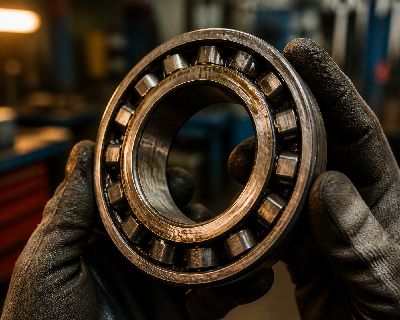
Bearing fatigue from continuous axial thrust is the most common life-limiting failure in extruder gearboxes. Unlike conveyor or pump gearboxes that handle primarily radial loads, an extruder gearbox's thrust bearing assembly absorbs sustained axial forces — often hundreds of kilonewtons — generated by pressurized material pushing the screws rearward toward the drive. Over millions of load cycles, subsurface fatigue cracks initiate in the bearing raceway steel, propagating until material spalls away from the surface. Condition monitoring data shows that bearing degradation accounts for roughly 20% of all industrial gearbox failures, but in extruder applications where axial thrust is a constant companion, that figure is likely higher. Rising iron and chrome particle counts in oil analysis are the earliest detectable signals of extruder gearbox bearing fatigue causes, often appearing 4 to 8 weeks before vibration symptoms become obvious.
Gear tooth pitting from inadequate lubrication is the second most prevalent failure mode. Pitting occurs when repeated contact stresses exceed the surface fatigue strength of the gear material — and insufficient lubricant film thickness dramatically accelerates the process. As gear failure analysis research documents, pitting typically begins just below the pitch line in the dedendum, where sliding velocity is highest and the lubricant film is thinnest. In extruder gearboxes, the problem is compounded by thermal effects: gearbox oil temperatures often run elevated due to proximity to heated barrels, and high ambient temperatures thin the oil film precisely when loads are greatest. Destructive pitting — the progressive type that grows in both pit size and number — results from surface overload conditions that initial corrective pitting could not smooth out. Left unchecked, pitting eventually forms fatigue cracks that can lead to tooth breakage.
Shaft seal degradation leads to oil leaks that seem minor at first but signal a deeper problem. Extruder gearbox output shaft seals operate in an exceptionally hostile zone — rotating shafts, elevated temperatures from barrel heating, and process-side contaminants that can attack elastomer seal lips. Once a seal begins weeping, lubricant loss is only part of the issue. The bigger threat is ingress: dust, polymer fines, and moisture entering the gearbox housing through the compromised seal. Silicon levels spiking in oil analysis — an indicator of dirt and abrasive contamination entering via damaged seals or breathers — accelerate every other wear mechanism simultaneously.
Thermal damage from overloading is the failure mode that punishes misspecification most directly. Running a gearbox beyond its thermal rating — by overloading it, by operating at speeds above the manufacturer's recommendation, or by allowing the lubrication cooling system to degrade — causes oil to oxidize rapidly, accelerates bearing fatigue, and can warp gear shafts. A gearbox operating consistently above its rated thermal capacity may show no immediate symptoms but will reach catastrophic failure far earlier than one operating within its design envelope.
Motor Failures and Electrical Drive Issues
On the motor side of the drive system, failure modes are equally specific and equally preventable — if you know what to look for.
Winding insulation breakdown is the leading cause of motor failure in extrusion environments. The motor sits near a barrel that may run at 200 to 350°C, creating thermal cycling that stresses insulation materials with every startup and shutdown. Each thermal cycle causes microscopic expansion and contraction in the winding insulation, gradually degrading its dielectric strength until a turn-to-turn short develops. Once a short forms, localized heating accelerates destruction of adjacent insulation, and the motor fails — often within days. Regular insulation resistance testing (megger testing) catches degradation trends long before a short occurs.
Bearing wear from misalignment between the motor shaft and gearbox input shaft concentrates load on one side of the bearing, causing uneven raceway wear and elevated vibration at 2x running speed. Even a few thousandths of an inch of angular or parallel offset creates forces that compound over time. Misalignment also stresses the coupling, which may mask the problem by absorbing vibration until it fails suddenly.
VFD-induced bearing damage is a failure mode that many maintenance teams never consider — yet it affects virtually every motor controlled by a variable frequency drive. The high-speed switching frequencies of the insulated-gate bipolar transistors (IGBTs) inside modern VFDs induce voltages on the motor shaft — often 70 volts peak-to-peak or more — during normal operation. Once this voltage overcomes the dielectric resistance of the bearing grease film, it discharges through the bearing, creating electrical discharge machining (EDM) pits and fusion craters in the race wall. This phenomenon repeats with virtually every VFD switching cycle, progressively frosting the bearing surface until fluting, excessive noise, and catastrophic bearing failure occur. Evidence suggests that VFD-induced bearing damage in extruder motors can cause failures within 3 to 12 months of startup in unmitigated systems — a fraction of the 100,000-hour design life typical bearings are engineered to achieve. Mitigation strategies include shaft grounding rings, insulated bearings, and ceramic bearing elements, though each comes with trade-offs in cost and applicability.
Cooling system fouling rounds out the motor failure landscape. Totally enclosed fan-cooled (TEFC) motors rely on external fin surfaces for heat dissipation. In extrusion environments filled with polymer dust, pellet fines, and additive powders, those fins clog progressively, reducing cooling capacity. The motor runs hotter, insulation degrades faster, and bearing grease breaks down sooner. A motor that is perfectly sized thermally at commissioning can become chronically overheated within a year if nobody cleans the cooling surfaces.
Preventive Maintenance Best Practices
The good news is that every failure mode described above is detectable before it becomes catastrophic — and most are preventable with disciplined, scheduled maintenance. Here is an extruder gearbox preventive maintenance checklist that covers both the gearbox and motor:
- Gearbox oil analysis (monthly for critical assets, quarterly for standard): Test for iron, copper, silicon, viscosity change, total acid number (TAN), and water content. Industry benchmarks flag iron above 100 ppm as a caution level and above 200 ppm as critical. Water content above 0.1% causes hydrogen embrittlement in bearing steel and drastically reduces oil film strength. Viscosity shifts greater than 15% from baseline indicate the oil can no longer protect gear tooth flanks under load.
- Vibration monitoring (monthly route-based or continuous online for critical gearboxes): Track gear mesh frequency sidebands for tooth wear, bearing defect frequencies (BPFO, BPFI) for raceway damage, and 2x running speed harmonics for misalignment. Rising kurtosis values above 4.0 indicate impulsive energy from early-stage defects.
- Thermal imaging (quarterly): Scan gearbox housing, motor frame, bearing housings, and coupling guards for hot spots that indicate overloading, bearing distress, or cooling system degradation. Compare against baseline thermograms taken during known-good operating conditions.
- Alignment verification (at commissioning, after any motor or gearbox replacement, and annually): Laser alignment between motor and gearbox shafts to manufacturer tolerances. Even slight misalignment causes bearing damage and coupling wear that compounds over months.
- Motor insulation resistance testing (semi-annually): Megger test motor windings at rated voltage. Trending insulation resistance over time catches degradation before a winding short develops. A reading below 5 megohms warrants investigation; below 2 megohms demands immediate action.
- Shaft seal inspection (monthly visual, replacement on condition): Check for oil weeping at gearbox output shaft seals and motor shaft seals. Any visible leakage indicates seal lip wear and potential contamination ingress path.
- Cooling system cleaning (quarterly or as needed): Clean motor cooling fins, check gearbox oil cooler flow rates, and verify fan operation. Fouled cooling surfaces are one of the most common — and most easily prevented — root causes of thermal damage.
Among all of these, gearbox oil analysis for twin screw extruder applications stands out as the single most impactful practice. Lubricant quality is the most important controllable factor in gearbox longevity because contaminated or degraded oil accelerates every failure mode simultaneously — it thins the film that prevents pitting, carries abrasive particles that score bearing raceways, and corrodes seal materials that would otherwise last years. A single $50 to $150 oil sample analyzed monthly provides more actionable intelligence about internal gearbox health than any external inspection can reveal.
Beyond monitoring and analysis, maintaining an inventory of critical spare parts deserves equal attention. When a thrust bearing fails or a shaft seal degrades to the point of replacement, lead times for OEM-sourced components can stretch to weeks or months — turning a planned repair into an extended production outage. Keeping wear components on hand — seals, bearings, coupling elements, and the process-side parts that interface with the drive system like screw elements, heater bands, and thermocouples — compresses repair timelines dramatically. For teams that need to source replacement components quickly, suppliers like NANHAIYA offer a practical option, providing screw elements, heater bands, thermocouples, and custom parts fabricated from drawings or samples that can bridge the gap during emergency gearbox and motor-adjacent repairs. The goal is not to stockpile every possible part, but to identify the components most likely to fail based on your specific application and operating history, and ensure they are accessible when needed.
Catching failures early and maintaining the drive system proactively keeps your extruder running — but even the best maintenance program cannot compensate for a gearbox or motor that was incorrectly specified in the first place. The specification errors engineers make most often, and how to avoid repeating them, reveal patterns that are surprisingly consistent across industries and machine sizes.
Common Mistakes When Specifying Twin Screw Extruder Gearboxes and Motors
Knowing the failure modes is one thing. Preventing them from ever gaining a foothold is another — and that prevention starts long before the gearbox arrives on the loading dock. It starts during specification. The same twin screw extruder gearbox sizing errors show up again and again across plants, industries, and machine sizes, often made by experienced engineers who simply never had a reason to question their assumptions. Here are the six most common mistakes specifying extruder gearbox and motor combinations — and practical guidance on how to sidestep each one.
Oversizing Motors While Undersizing Gearboxes
This is the single most dangerous specification error, and it is alarmingly common. An engineer calculates the motor power needed for the target throughput, adds a comfortable safety margin, and selects a motor that can deliver well beyond the application's steady-state demand. So far, so reasonable. The problem emerges when the gearbox is then selected with a torque capacity that matches the application's expected running load rather than the motor's full output capability. The result? The motor can deliver more torque than the gearbox can mechanically survive. During a startup surge, a sudden viscosity spike, or even a momentary feed blockage, the motor pushes full torque through a gearbox that was never designed to handle it. Gear teeth crack. Thrust bearings overload. And the failure gets blamed on "a bad gearbox" when the real culprit was a mismatched specification.
The fix is simple in principle: always verify that your gearbox's continuous-duty torque rating exceeds the maximum torque your motor and drive can physically deliver — not just the torque your process normally requires. If the motor can output 25,000 Nm through the gearbox ratio, the gearbox must handle 25,000 Nm, regardless of whether your process typically runs at 16,000 Nm.
Specification Traps and Rating Standard Differences
Beyond the motor-gearbox mismatch, several subtler traps catch even careful buyers. Each one seems minor in isolation but compounds with the others to create a specification that looks adequate on paper and fails in practice.
- Confusing nominal and peak torque ratings: Gearbox catalogs often display a peak torque figure prominently — say, 12,000 Nm — while the continuous-duty rating hides in the footnotes at 8,000 Nm. If you size your screw to exploit that peak number, you are running the gearbox at 100% of its real capacity during every production hour. Industry guidance recommends operating at 80% of continuous rating, not 80% of peak. That single distinction between nominal vs peak torque rating extruder gearbox specifications prevents most early-life bearing fatigue failures. Always ask the supplier to clearly state continuous-duty torque at the intended output speed, separate from any intermittent or peak rating.
- Selecting a gearbox on catalog price alone: A lower-priced gearbox with 10 Nm/cm³ torque density may seem like a bargain next to a unit delivering 15 Nm/cm³ at higher cost. But that lower torque density means you are buying a physically larger, heavier unit that occupies more floor space, demands more structural support, and may still lack the capacity headroom for future process upgrades. Torque density determines long-term value — cost per Nm delivered over the gearbox's service life — and a cheaper unit that fails two years early or limits your throughput growth costs far more than the price premium of a higher-density design.
- Neglecting axial thrust bearing capacity: Engineers meticulously calculate torque requirements and then completely overlook thrust loads. As discussed in earlier sections, thrust bearing fatigue frequently limits gearbox life before gear wear does. Back-pressure from the die pushes screws rearward with forces that can reach thousands of kilonewtons on large production extruders. If the gearbox's thrust bearing assembly is not rated for the actual axial forces your process generates — including transient spikes during startup — you will replace thrust bearings on a cycle that no maintenance budget anticipated. Always request the gearbox's rated axial thrust capacity and compare it against calculated back-pressure forces for your specific die geometry, material, and operating pressures.
- Sizing only for steady-state conditions: Steady-state running torque is the easiest number to calculate, so it becomes the default sizing basis. But extrusion is not a steady-state process. Cold material in the barrel during startup can spike torque 20 to 40% above running levels. Feed rate fluctuations, gel slugs in recycled feedstock, and material changeovers all generate momentary overloads that the drive system must absorb without damage. If you size the gearbox to handle only the average running load, every transient event pushes it into its overload zone — precisely the condition that accelerates fatigue in gears and bearings. Build in a service factor that reflects your application's actual load profile, including worst-case transients, not just the calm middle of a production run.
- Assuming all manufacturers use the same rating standards: This may be the most insidious trap of all, because it is invisible on any individual spec sheet. A comparative analysis of eight commonly used rating standards — including API 613, AGMA 2001, AGMA 6013, and ISO 6336 — found roughly a two-to-one ratio between the highest and lowest ratings for identical gear sets. The same physical gearbox can be rated at dramatically different torque values depending on which standard the manufacturer applies, what material grade assumptions are used, and what design life the rating targets. AGMA 6013 rates for 10,000 hours. AGMA 6011 rates for a minimum of 40,000 hours. API 613 uses the most conservative material allowables dating back to 1977 — unchanged despite decades of improved metallurgy. When comparing gearboxes from different suppliers, you must ask which rating standard was used, what design life assumption underlies the rating, and whether the quoted figure is for pitting resistance, bending strength, or the lower of the two. Without that context, you are comparing numbers that look equivalent but may reflect fundamentally different engineering assumptions.
How to Avoid Costly Selection Errors
The pattern connecting all six mistakes is the same: each one results from evaluating a single specification in isolation instead of treating the motor and gearbox as a coupled system operating within a specific application context. To avoid extruder gearbox selection mistakes, adopt three practices that consistently separate successful specifications from expensive mismatches:
- Specify from the screw backward, not the motor forward. Lock your screw geometry, L/D ratio, and target throughput against material rheology first. Then calculate the continuous torque per shaft, axial thrust, and speed range the gearbox must deliver. Only then select the motor that provides the required power at a speed compatible with the gearbox ratio. This sequence prevents the motor from dictating demands the gearbox cannot meet.
- Demand apples-to-apples rating comparisons. Require every gearbox supplier to state their torque rating against a named standard, a specific design life, and a declared service factor. If one supplier quotes AGMA 6013 at 10,000 hours and another quotes ISO 6336 at 100,000 hours, the numbers are not comparable without normalization.
- Build the actual load profile into your specification. Document cold-start conditions, material changeover scenarios, and the worst-case feedstock your line may process over the next three to five years. Share this with the gearbox and motor supplier. A responsible supplier will use it to recommend a service factor and overload margin that matches reality — not the optimistic steady-state assumption that looks best on a quotation but fails first in the field.
Avoiding these specification errors puts you on solid ground mechanically. The remaining challenge is a commercial one — finding suppliers who can deliver the right gearbox, the right motor, and the supporting components your maintenance team needs, at terms and lead times that keep your line running.
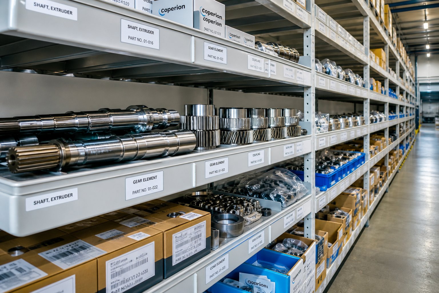
How to Choose the Right Twin Screw Extruder Gearbox Supplier and Drive System Partner
A flawless specification on paper means nothing if the supplier behind it cannot deliver on time, support the installation technically, or stand behind the product when something goes wrong three years later. The commercial side of sourcing twin screw extruder gearboxes and motors is where many procurement teams stumble — not because they lack purchasing skill, but because the evaluation criteria that matter most for precision drive components are different from those that govern commodity industrial purchases. A gearbox is not a pipe fitting. The cheapest quote is rarely the best value, and the most expensive one is not automatically the safest bet.
Supplier Evaluation Criteria That Matter Most
Imagine two gearbox suppliers quoting the same torque rating at the same center distance. The prices differ by 18%. Which do you choose? If your answer is "the cheaper one," you are making the same mistake that fills maintenance shops with prematurely failed gearboxes. Structured quote comparison frameworks consistently show that the real differentiators between suppliers lie beneath the price line — in technical depth, service responsiveness, and total cost of ownership.
Here are the evaluation criteria that experienced plant buyers and machine rebuilders prioritize:
- Technical support capability: Can the supplier's engineering team discuss your application in detail — service factors, load profiles, screw geometry constraints, and motor compatibility? A supplier who asks about your process conditions before quoting is far more trustworthy than one who simply matches catalog numbers to your RFQ. If a supplier cannot answer technical questions or avoids reviewing application details, that should raise a flag.
- Lead times and inventory position: Standard build-to-order lead times for specialized extruder gearboxes can stretch to 12 to 20 weeks. For a planned upgrade, that is manageable. For an emergency replacement with production down, it is devastating. Ask whether the supplier stocks finished units, offers expedited manufacturing, or can provide remanufactured alternatives to bridge the gap. A gearbox that costs slightly more but arrives in two weeks instead of sixteen may save your plant tens of thousands in lost production.
- Custom configuration availability: Twin screw extruder drive systems are rarely off-the-shelf commodities. Your center distance, shaft orientation, mounting style, and ratio requirements may not match a standard catalog offering. Suppliers willing to work from your existing drawings or reverse-engineer from samples — rather than forcing you into their standard product matrix — provide significantly more flexibility for retrofit and rebuild projects.
- Geographic proximity for service: When a gearbox needs field inspection, alignment verification, or emergency repair support, having a supplier with regional service capability matters. Remote technical support via phone or video handles many issues, but hands-on troubleshooting sometimes requires boots on the ground.
- Warranty terms and documentation quality: Not all warranties are equal. Review coverage duration, exclusions for misapplication or overload, required maintenance records, and the claim process itself. A one-year warranty with clear terms and responsive support may be more valuable than a longer warranty filled with exclusions. Request test reports, dimensional drawings, material certifications, and maintenance manuals — for regulated industries, documentation can be as important as the gearbox itself.
- Total cost of ownership versus upfront price: A gearbox with higher mechanical efficiency — say 97% versus 94% — saves 3% of input power continuously. On a 400 kW drive running 8,000 hours per year, that is roughly 96,000 kWh annually. At $0.10/kWh, the more efficient unit saves $9,600 per year in electricity alone. Factor in reduced thermal stress on lubricant and bearings, fewer oil changes, and extended service life, and the extruder gearbox and motor total cost of ownership picture shifts dramatically away from the lowest purchase price.
Global Sourcing Landscape and Regional Strengths
The twin screw extruder gearbox sourcing guide would be incomplete without acknowledging the global manufacturing landscape. Gearbox and motor suppliers span multiple continents, each region bringing distinct strengths to the table.
European manufacturers — particularly those in Germany, Italy, and Switzerland — have historically set the benchmark for precision engineering, metallurgical quality, and maximum torque density. Companies in this region pioneered many of the integrated planetary architectures discussed earlier in this article, and they maintain the tightest manufacturing tolerances available. The trade-off is cost and lead time: European-sourced gearboxes typically carry the highest price premium and longest delivery windows, reflecting both labor costs and the depth of engineering that goes into each unit.
Chinese manufacturers have evolved dramatically over the past decade. Current industry analysis shows that leading Chinese suppliers now deliver advanced engineering that meets international standards, combining competitive pricing — often 40 to 60% below European equivalents — with increasingly sophisticated manufacturing capabilities. The strongest Chinese suppliers offer complete system integration, including gearbox, motor, screw elements, and downstream equipment, which simplifies procurement for plants building entire new lines. Lead times from China tend to be shorter than European suppliers for standard configurations, though custom engineering projects may require more oversight to ensure specification compliance.
North American suppliers excel in regional service infrastructure and rapid response for installed base support. If your plant is in the U.S. or Canada and you need emergency gearbox repair, field alignment, or on-site troubleshooting, domestic suppliers offer response times that overseas manufacturers cannot match. They also provide localized spare parts inventories that compress downtime during unplanned repairs.
Indian manufacturers occupy a growing niche in the cost-competitive segment, particularly for standard helical gearbox configurations. Quality varies more widely across the Indian supplier base than in other regions, making due diligence and factory audits especially important when sourcing from this market.
The right choice depends on your priorities. A new greenfield compounding line with a 12-month construction timeline has different sourcing needs than an emergency gearbox replacement on a production line that is down right now. Matching regional strengths to your specific situation — rather than defaulting to brand familiarity or lowest price — is how experienced procurement teams consistently get better outcomes.
Questions to Ask Extruder Gearbox Suppliers Before You Commit
One of the most effective ways to separate qualified suppliers from order-takers is to ask every candidate the same set of pointed questions. This creates a level playing field and reveals gaps in technical depth or service capability that promotional materials never mention.
- Which rating standard (AGMA, ISO 6336, API, or proprietary) was used to determine the quoted torque capacity, and what design life does that rating assume?
- What is the continuous-duty torque rating at my specific output speed — not the catalog peak or intermittent figure?
- What is the rated axial thrust capacity of the thrust bearing assembly, and how does it compare to my calculated process back-pressure?
- Can you provide a dimensional drawing confirming mounting compatibility with my existing installation — shaft centerline height, bolt pattern, and coupling interface?
- What is your standard lead time, and what expedited options are available if my timeline changes?
- Do you offer gearbox repair, rebuild, or remanufacturing services in addition to new units?
- Can you work from my existing drawings, samples, or nameplate data to produce a compatible replacement — even if the original manufacturer no longer supports the model?
- What lubricant type and grade do you recommend, and what oil analysis parameters should I monitor for this specific gearbox design?
- What is included in the quoted price — coupling, motor adapter, torque arm, lubricant, shipping, documentation — and what is excluded?
- What warranty terms apply, and what maintenance records do I need to maintain for the warranty to remain valid?
Any supplier who cannot answer these questions clearly, or who deflects with vague responses, is telling you something important about the level of support you will receive after the purchase order is signed.
Simplifying Your Extruder Parts Supply Chain
There is a practical dimension to supplier selection that goes beyond the gearbox and motor themselves. Twin screw extruders are systems, and the drive components do not fail in isolation from the rest of the machine. When a thrust bearing replacement requires pulling the screw shafts, you will also want fresh screw elements, new barrel liner seals, and possibly replacement heater bands and thermocouples on hand to complete the overhaul in a single maintenance window. If those components come from five different suppliers with five different lead times, your two-day repair stretches into two weeks of waiting for parts.
This is why supply chain consolidation — a well-documented strategy in MRO procurement — applies directly to extruder maintenance. Reducing the number of suppliers you depend on for wear components simplifies ordering, reduces administrative overhead, and compresses repair timelines. The ideal scenario is working with partners who can supply not just the gearbox or motor, but also the adjacent process-side components that you will inevitably need alongside drive system repairs.
Suppliers like NANHAIYA serve exactly this consolidation role, offering a broad catalog of replacement components — screw elements, die heads, pelletizing blades, heater bands, thermocouples, and custom parts fabricated from drawings or samples — that maintenance teams and machine rebuilders frequently need during gearbox and motor-adjacent work. Having a single sourcing partner for these wear items, alongside your gearbox and motor suppliers, reduces the number of purchase orders, streamlines inventory management, and ensures that when a major drive system repair opens the machine, every component needed to close it back up is already on its way.
This supply chain thinking reinforces the central message that has run through every section of this article: the motor and gearbox are not isolated purchases. They are interconnected components within a larger system that includes screw geometry, process conditions, application demands, maintenance practices, and spare parts logistics. Engineers who treat them as a coupled system — specified together, monitored together, and supported by a consolidated supply chain — consistently achieve better performance, longer service life, and lower total cost of ownership than those who optimize each piece in a silo.
Whether you are designing a new extrusion line, retrofitting an aging drive, or troubleshooting chronic failures on an existing machine, the framework is the same. Start with the screws and work backward through torque, speed, and thrust to size the gearbox. Match the motor to the gearbox's input requirements and your process speed range. Evaluate suppliers on technical depth, not just price. And build a maintenance and sourcing strategy that treats the entire drive system — and the wear components that surround it — as one integrated investment in your plant's uptime and throughput.
Frequently Asked Questions About Twin Screw Extruder Gearboxes and Motors
1. What does a twin screw extruder gearbox actually do?
A twin screw extruder gearbox performs three simultaneous mechanical tasks that standard industrial gearboxes do not handle together. It reduces high motor speed (typically 960-1,480 RPM) to the lower screw speed range (15-600 RPM), multiplies torque proportionally as speed decreases, and absorbs substantial axial thrust loads generated by pressurized material pushing the screws rearward toward the drive. This thrust can range from a few kilonewtons on lab machines to over 3,400 kN on large production units. Because all three tasks occur continuously and simultaneously, extruder gearboxes require purpose-built designs with specialized thrust bearing assemblies, hardened gear trains, and robust lubrication systems that far exceed what conventional speed reducers provide.
2. How do I choose between AC induction, DC, and permanent magnet motors for a twin screw extruder?
AC induction motors paired with variable frequency drives (VFDs) are the current industry standard for new installations, offering rugged construction, precise speed control, and low maintenance. DC motors still power many legacy lines but are being phased out due to brush and commutator wear, plus declining parts availability. Permanent magnet synchronous motors (PMSM) represent the high-efficiency frontier, cutting energy consumption by 5-15% compared to equivalent IE3 induction motors thanks to eliminated rotor copper losses. Your choice depends on priorities: AC induction for reliability and cost balance, PMSM for energy savings and compact footprint, and DC replacement with AC systems when legacy drives reach end of life. Always match the motor's constant-torque speed range to your process demands through the correct gearbox ratio.
3. What is torque density in a twin screw extruder gearbox and why does it matter?
Torque density, measured in Nm/cm3, expresses how much output torque a gearbox delivers relative to the cube of its center distance. Higher torque density means more torque capacity packed into a smaller, lighter housing. Earlier-generation gearboxes typically achieved around 10 Nm/cm3, while modern integrated planetary designs now reach 17-18 Nm/cm3 — nearly doubling usable torque for the same gearbox size. This matters practically because higher torque density lets you process tougher, more viscous formulations or achieve higher throughput without upsizing the entire machine frame. When comparing gearbox quotes, torque density is a better indicator of long-term value than catalog price alone, since it directly reflects how much productive work the gearbox can deliver per unit of installed space.
4. What are the most common failure modes in twin screw extruder gearboxes?
Four failure modes dominate twin screw extruder gearbox breakdowns. Bearing fatigue from continuous axial thrust is the most frequent life-limiting issue, detectable early through rising iron and chrome particle counts in oil analysis. Gear tooth pitting from inadequate lubrication follows, caused when oil film thickness drops below safe levels due to thermal degradation or contamination. Shaft seal degradation allows lubricant loss and contaminant ingress simultaneously, accelerating all internal wear mechanisms. Thermal damage from overloading rounds out the list, caused by exceeding the gearbox's thermal rating through sustained overload or cooling system neglect. Monthly oil analysis is the single most cost-effective preventive measure, as contaminated or degraded lubricant accelerates every failure mode at once. Maintaining critical spare parts — including seals, bearings, and process-side components from suppliers like NANHAIYA (nhyscrews.com) — further reduces unplanned downtime.
5. Why is it dangerous to oversize the motor while undersizing the gearbox on a twin screw extruder?
This is the most common and most dangerous specification error in extruder drive systems. When an oversized motor can deliver more torque than the gearbox is mechanically rated to handle, any transient event — a cold startup, a viscosity spike, or a feed blockage — can push full motor torque through a gearbox that was never designed for it. The result is cracked gear teeth, overloaded thrust bearings, and premature gearbox failure that gets misdiagnosed as a manufacturing defect. To prevent this, always verify that the gearbox's continuous-duty torque rating exceeds the maximum torque your motor and drive can physically deliver at the gearbox output speed — not just the torque your process typically requires during steady-state operation. A 10-20% margin above the motor's maximum deliverable torque provides a practical safety buffer.
Written by
Nanhaiya Technical Team
Zhoushan Nanhaiya Plastic Machinery Co., Ltd.
The Nanhaiya technical team supports screw and barrel manufacturing projects through application review, technical communication, custom manufacturing coordination, and production and quality control.
Discuss Your Application
Related Articles
More insights on screw barrel technology and plastics processing.

What Nobody Tells You About Screw Barrel For Plastic Machine Design
Oct 10, 2026
Learn how screw barrel for plastic machine design affects melt quality, throughput, and wear life. Covers geometry, resin matching, troubleshooting, and sourcing.
Read Article
Single Screw Extruder for Sheet: Stop Guessing, Start Specifying
Oct 9, 2026
Learn how to specify a single screw extruder for sheet production. Covers screw geometry, resin-specific processing, troubleshooting, and maintenance best practices.
Read Article
PE Pipe Extruder Machine: What Datasheets Won't Tell You
Oct 9, 2026
Learn how a PE pipe extruder machine works, key specs explained, material grade selection, maintenance tips, and buyer guidance beyond the datasheet.
Read ArticleLooking for something else?
Search by material, symptom or product and jump straight to the relevant page.
These are navigation suggestions based on keyword matching — not a quotation, not a delivery commitment, and not a substitute for engineering review. Final specification is confirmed by our engineers against your drawings and processed material.
Need help with screw barrel selection?
Share your machine model, processed material and application. Our team can help with pricing and technical support.