

What Twin Screw Extruder Gearbox Design Actually Involves
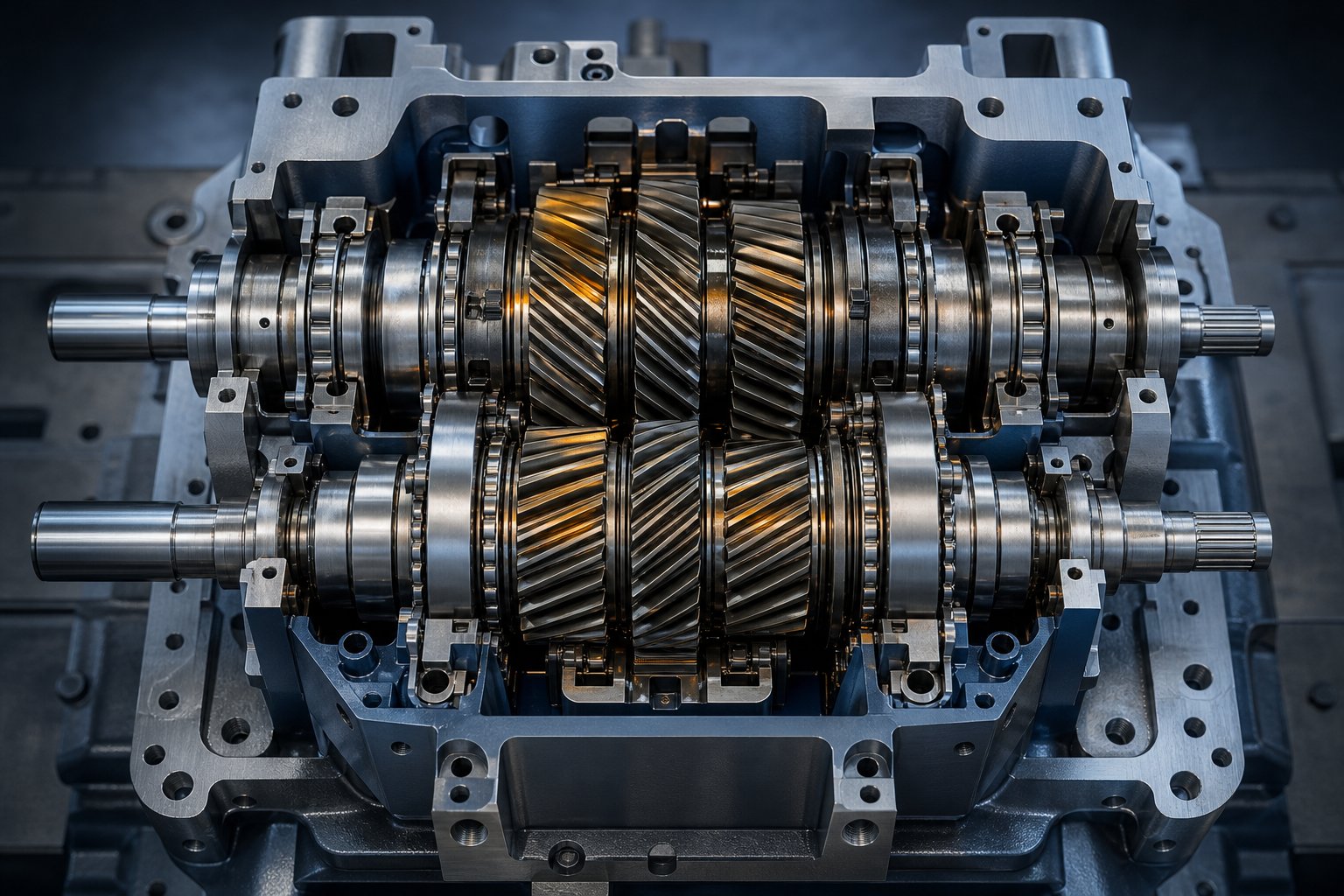
Twin screw extruder gearbox design is the engineering discipline of creating a power transmission subsystem that converts high-speed, low-torque motor output into synchronized, high-torque rotation of two parallel screws. It encompasses three simultaneous mechanical functions: speed reduction, torque multiplication, and precise torque splitting across two output shafts—all while absorbing substantial axial thrust forces generated by the extrusion process itself.
Sounds straightforward? It isn't. Unlike a single-screw extruder gearbox, which drives one output shaft, a twin screw gearbox must deliver precisely equal torque to two shafts spinning at the same speed within extremely tight center distances. The screw outer diameter and the intermeshing zone between the two screws dictate how close together those output shafts must sit, and that spacing leaves engineers remarkably little room for gears, bearings, and the structural housing around them. This is what makes the gearbox the most technically demanding—and often the most expensive—component on the entire extruder.
Defining the Twin Screw Extruder Gearbox and Its Role
To understand how a twin screw extruder gearbox works, imagine the motor spinning at high RPM but with relatively modest torque. The gearbox steps that speed down through multiple gear stages, multiplying torque at each reduction. A three-stage gearbox, for instance, might reduce motor speed by a factor of 10 or more while increasing torque proportionally. The final stage then splits that amplified torque into two equal output paths—one for each screw shaft.
The twin screw extruder gearbox function goes beyond simple power conversion. It must also absorb the axial thrust that the screws generate as they push molten polymer toward the die. In twin screw extruders, these back-pressure forces can range from 2.5 kN for small machines to 3,400 kN for large production units. The thrust bearing arrangement within the gearbox handles this load, and undersizing it is one of the most common specification errors engineers make. In fact, thrust bearing capacity frequently limits gearbox life before torque capacity does.
Gearbox torque splitting for twin screw extruders adds a layer of complexity that single-screw designs simply don't face. Any imbalance in the torque distribution between the two output shafts causes uneven screw loading, accelerated wear on one side, vibration, and inconsistent melt processing. Maintaining angular synchronization is equally critical—even a fractional-degree timing error under load can cause the intermeshing screws to interfere, sending damaging shock loads back through the gear train.
Why Gearbox Design Matters for Extrusion Performance
Every performance parameter downstream of the gearbox—process throughput, energy consumption, achievable screw speed range, and overall machine lifespan—traces back to decisions made during gearbox design. Twin screw gearbox speed reduction and torque multiplication ratios determine the operating envelope. Choose the wrong reduction ratio, and you'll either lack the torque for high-viscosity compounding or sacrifice the speed range needed for devolatilization applications.
Consider the systems-engineering perspective. Motor selection upstream must align with gearbox thermal capacity and reduction ratio. Screw configuration downstream depends on the torque curve and speed range the gearbox can deliver. Modern twin screw extruders achieve torque densities of 18 Nm/cm³, a 30% increase over previous generations—but that improvement came from gearbox engineering breakthroughs, not motor or screw changes alone. A three-stage gearbox with 97% efficiency per stage delivers only about 91% overall efficiency, and the remaining 9% becomes heat that must be managed to protect lubricant integrity and bearing life.
In most twin screw extruder performance upgrades, the gearbox is the true limiting factor—not the motor, not the screws, and not the barrel. You can install a more powerful drive and redesign the screw profile, but if the gearbox cannot handle the resulting torque, axial thrust, and thermal load within its center distance constraints, the entire investment is wasted.
This reality is exactly why a deep, engineering-level understanding of gearbox architecture matters—and why the torque-splitting mechanism at the heart of every twin screw gearbox deserves closer examination.
The Engineering Challenge of Torque Splitting Between Twin Shafts
Splitting one stream of power into two perfectly equal outputs sounds like a clean mathematical exercise. In practice, it is one of the most demanding problems in industrial gearbox engineering. The twin screw gearbox torque distribution mechanism must deliver exactly half the total torque to each output shaft, maintain identical rotational speeds, and accomplish both tasks inside a housing so compact that every millimeter of space is contested by gears, bearings, and structural walls. Get the split wrong by even a small margin, and the consequences ripple through the entire extrusion process.
How Torque Splitting Works in Twin Screw Gearboxes
Picture the power path from motor to screws. The motor drives a single input pinion, which engages an intermediate gear stage responsible for speed reduction and torque multiplication. At the splitting point, power must diverge into two separate gear paths—one for each output shaft connected to a screw. The equal torque split in a twin screw extruder gear train hinges on this divergence point being geometrically and mechanically balanced.
Why does equal distribution matter so much? When one shaft receives more torque than the other, the overloaded screw experiences accelerated wear at the flight tips and intermeshing zone. The underloaded screw, meanwhile, conveys material at a slightly different rate. You'll notice uneven melt temperatures, inconsistent residence times, and subtle product quality variations that are difficult to diagnose because they don't point obviously to the gearbox. Vibration also increases, shortening bearing life and degrading gear tooth surfaces over thousands of operating hours.
The geometric constraint tightening this challenge even further is center distance. The outer diameter of each screw and the depth of their intermeshing zone fix the distance between the two output shaft centerlines. In a typical co-rotating twin screw extruder, this center distance is remarkably small relative to the torque being transmitted. Engineers are left trying to fit adequate gear teeth, sufficient bearing envelopes, and robust shaft cross-sections into a space that resists every attempt at expansion. As Portescap's research on center distance variation demonstrates, even housing bore position tolerances of 30 to 80 microns can cause measurable shaft misalignment, increased transmission error, and noise levels climbing from 38 dBA to over 52 dBA. In twin screw gearboxes operating under far higher loads, these center distance constraints in twin screw gearbox design become a defining engineering boundary.
Gear Train Configurations for Equal Load Distribution
Engineers have developed two fundamental approaches to splitting torque, and understanding the trade-offs between them is critical for anyone specifying or evaluating a gearbox.
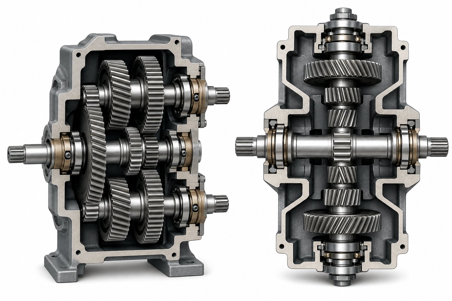
The first approach is the parallel three-axis (sequential) structure. Imagine a single input pinion meshing with one intermediate gear, which then drives both output shafts in sequence through parallel gear paths. In this layout, one output shaft—call it shaft A—sits in a favorable position with ample space for large gears and robust bearings. The second output shaft, shaft B, is constrained by the tight center distance and must use smaller gears. The result? Shaft B becomes the weak link. It bears significant combined bending and torsion loads, and the bearing on the B-axis typically reaches its life limit around 20,000 hours due to continuous unidirectional radial loading. To compensate, some improved sequential designs split the B-axis load across two gear sets, reducing each set's torque share from 50% to 25% and effectively doubling the torque capacity—but the fundamental load imbalance between shafts remains.
The second approach is the symmetric (double-sided) torque splitting gearbox structure. Here, power divides into upper and lower gear paths that drive the constrained B-axis from opposite directions simultaneously. This is where the engineering elegance emerges. The radial forces from the two gear meshes on shaft B act in opposing directions and cancel each other out, reducing the net radial bearing load to essentially zero. Shaft B becomes a pure torque output shaft—subjected only to torsion, not combined bending-torsion stress. The practical impact is dramatic: bearing service life on the B-axis can extend to approximately 72,000 hours, roughly 3.6 times the lifespan achievable with the sequential arrangement. Radial runout remains stable over the gearbox's lifetime, preserving consistent screw-to-barrel clearances and uniform melt processing.
The symmetric vs sequential torque splitting gearbox decision involves clear trade-offs. The sequential design wins on simplicity, manufacturing cost, and ease of assembly. The symmetric design wins on load balance accuracy, bearing life, output stability, and maximum achievable torque density. The table below maps these differences across the parameters that matter most during gearbox selection.
| Parameter | Sequential (Parallel Three-Axis) | Symmetric (Double-Sided Drive) |
|---|---|---|
| Load Balance Accuracy | Moderate—inherent imbalance between A and B shafts due to asymmetric gear paths | High—opposing gear meshes cancel radial forces on the constrained shaft, creating a pure couple drive |
| B-Axis Bearing Life | ~20,000 hours under continuous load; radial runout increases over time | ~72,000 hours; radial bearing load effectively eliminated, runout remains stable |
| Compactness | Good—fewer gear elements, smaller housing envelope | Moderate—requires additional gear stages above and below the B-axis, increasing vertical housing dimension |
| Manufacturing Complexity | Lower—simpler gear arrangement, standard assembly procedures | Higher—demands tighter machining tolerances and more complex assembly to align dual gear paths |
| Maximum Torque Density | Limited by B-axis gear and bearing capacity; can be improved with dual gear sets per shaft | Superior—balanced loading allows full utilization of gear and bearing capacity on both shafts |
| Output Stability Over Time | Degrades as B-axis bearing wears, increasing radial runout and vibration | Remains consistent—no progressive bearing wear on B-axis affects shaft position |
| Typical Applications | Cost-sensitive machines, lower-torque compounding lines, smaller extruder sizes | High-torque production extruders, applications requiring long-term process consistency and premium output quality |
What makes this comparison particularly relevant is the downstream effect on product quality. A sequential gearbox experiencing progressive B-axis radial runout changes the clearance between screw and barrel unevenly over time. Material residence time in the barrel becomes inconsistent, melt homogeneity suffers, and product variability creeps upward in ways that routine process adjustments cannot fully correct. The symmetric design eliminates this degradation mechanism entirely.
Of course, torque splitting is only half the mechanical story. The direction those two output shafts rotate—whether both spin the same way or in opposite directions—introduces an entirely different set of structural demands on the gearbox, from gear train architecture to axial thrust magnitudes that the bearing system must absorb.
How Co-Rotating and Counter-Rotating Configurations Shape Gearbox Design
Rotation direction is not a minor specification detail—it is a fundamental mechanical divergence that reshapes nearly every aspect of what the gearbox must accomplish. Two screws spinning the same way impose a completely different set of speed, torque, and thrust demands than two screws spinning in opposite directions. The gear train architecture, the bearing arrangement, even the physical geometry of the housing all shift in response. Yet many gearbox specification discussions treat rotation direction as a checkbox rather than a design driver. That oversight leads to mismatched components, premature wear, and process limitations that could have been avoided with a clearer understanding of what each configuration actually demands from the power transmission system.
Co-Rotating Gearbox Design Considerations
In a co-rotating twin screw extruder, both screws turn in the same direction—typically at high speeds. These machines dominate in compounding, reactive extrusion, devolatilization, and polymer blending applications where intense shear fields and self-wiping action are essential for achieving thorough mixing and narrow residence time distributions. The process demands translate directly into co-rotating twin screw extruder gearbox requirements that push mechanical design to its limits.
The first challenge is speed. Co-rotating extruders routinely operate at screw speeds of 300 to 1,200 RPM or higher, far exceeding what counter-rotating machines typically require. High rotational speed means the gearbox reduction ratio must be large enough to bring motor speed down while multiplying torque proportionally. Modern co-rotating machines target specific torque values reaching 18 Nm/cm³, and delivering that torque density at elevated speeds compounds the thermal and mechanical stress on every gear stage.
The second challenge is directional. Both output shafts must rotate the same way, but a standard gear mesh between two parallel shafts naturally produces opposite rotation. To achieve co-rotation, the gear train must include either a direction-reversing idler stage for one shaft or a symmetric splitting arrangement where both shafts are driven through separate, identically configured gear paths. Each approach adds components, consumes space, and introduces additional mesh points where power losses occur and heat accumulates.
The third—and arguably most constraining—challenge is center distance. Co-rotating screws use a fully intermeshing geometry where the flight of one screw sweeps through the channel of the other. This tight intermeshing dictates a small center distance between output shafts, which in turn leaves very little room for the radial and thrust bearings that must support each shaft. As one industry comparison notes, the small center distance in parallel twin screw extruders limits gear modulus, bearing diameter, and shaft cross-section, making poor torque resistance the most significant defect of this configuration. Engineers address this through precision manufacturing, high-grade bearing materials, and innovative stacking arrangements—but the spatial constraint never fully disappears. It simply defines the engineering boundary within which every other design decision must fit.
Counter-Rotating Gearbox Design Differences
Counter-rotating twin screw extruders spin their two screws in opposite directions. Imagine material being drawn into the intermeshing zone from both sides simultaneously, compressed, and pushed forward under high fill and relatively low rotational speed. This configuration excels in processing thermally sensitive materials like rigid PVC, where low shear stress and suppressed temperature rise are critical to preventing decomposition. PVC pipe, sheet, and profile extrusion lines rely heavily on this design.
From a pure gear-train perspective, counter-rotating gearbox design is simpler in one notable respect. A single gear mesh between two parallel shafts inherently produces opposite rotation—no idler gear or direction-reversing stage is needed. This reduces the component count, lowers manufacturing complexity, and eliminates one source of power loss and heat generation within the gearbox.
The complication, however, arrives through axial thrust. Counter-rotating screws operating at high fill levels generate substantial back pressure as material is compressed toward the die. Head pressures typically reach 14 MPa and can exceed 30 MPa in demanding applications. This pressure translates directly into axial thrust forces pushing each screw rearward into the gearbox. Counter-rotating gearbox axial thrust management becomes a defining design challenge—one that frequently determines bearing selection, housing stiffness, and ultimately the continuous-duty rating of the entire gearbox. In parallel counter-rotating machines, the same tight center distance constraints that plague co-rotating designs apply, making it difficult to install thrust bearings with adequate load capacity.
The conical twin screw variant introduces an additional layer of geometric complexity. In this design, the two screws taper from a large diameter at the feed end to a smaller diameter at the discharge end. The screw axes are no longer parallel—they converge at an angle, meaning the center distance between output shafts increases from the small end toward the large end. This diverging geometry gives the conical twin screw gearbox housing design a significant structural advantage: larger center distances at the drive end provide substantially more room for bearings and gears. Two large-diameter thrust bearings can be installed where a parallel design would require several small bearings stacked in series. The result is greater working torque, larger load capacity, lower manufacturing cost, and simpler maintenance compared to an equivalent parallel configuration. The trade-off is reduced flexibility in length-to-diameter ratio and a more complex housing geometry that must accommodate the angular shaft arrangement with precise alignment.
Matching Gearbox Architecture to Screw Configuration
Choosing between co-rotating and counter-rotating—and between parallel and conical screw geometries—is not purely a process decision. It is simultaneously a gearbox architecture decision. The co-rotating vs counter-rotating extruder gearbox comparison ultimately comes down to aligning mechanical capabilities with application demands across multiple interconnected parameters. When specifying or evaluating a gearbox, you'll want to weigh the following decision criteria:
- Rotation direction: Co-rotating designs require a direction-reversing gear stage or symmetric splitting arrangement; counter-rotating designs achieve opposite rotation through a single gear mesh, simplifying the gear train.
- Speed range: Co-rotating extruders typically demand high-speed capability (300-1,200+ RPM), requiring gearboxes optimized for thermal management at elevated speeds. Counter-rotating machines operate at lower speeds with higher fill, shifting the design emphasis toward torque capacity over speed.
- Torque requirements: Both configurations push torque density limits, but co-rotating compounding applications increasingly target 15-18 Nm/cm³, making torque density the primary gearbox benchmark for these machines.
- Axial load magnitude: Counter-rotating extruders generally produce higher axial thrust due to elevated head pressures and high-fill operation. The gearbox thrust bearing system must be sized accordingly, with conical designs offering a natural advantage through larger available bearing envelopes.
- Center distance constraints: Parallel twin screw designs—whether co-rotating or counter-rotating—impose severe center distance limitations that restrict bearing and gear size. Conical twin screw configurations relax this constraint at the drive end, enabling simpler, more robust bearing arrangements.
- Typical polymer applications: Co-rotating gearboxes serve compounding, reactive extrusion, devolatilization, and polymer blending where high shear and mixing intensity are essential. Counter-rotating gearboxes serve PVC pipe and profile extrusion, sheet production, and applications requiring gentle processing of thermally sensitive materials.
Each of these criteria interacts with the others. A co-rotating extruder targeting 18 Nm/cm³ torque density at 600 RPM presents a radically different gearbox engineering problem than a conical counter-rotating machine processing rigid PVC at 30 RPM with 25 MPa head pressure. The rotation direction sets the architectural framework, but the specific combination of speed, torque, thrust, and spatial constraints determines whether that framework succeeds or fails in service.
These configuration-level decisions establish what the gearbox must do. The next critical question is how it does it—specifically, which types of gears best meet the load capacity, noise, and efficiency requirements that each configuration demands.
Comparing Gear Types and Gearbox Architectures
Configuration and torque-splitting strategy define the structural blueprint of a twin screw extruder gearbox. But the gears themselves—their geometry, tooth engagement pattern, and load-carrying behavior—determine whether that blueprint actually performs under real-world extrusion conditions. Gear type selection for extruder gearbox applications is not a matter of picking the most advanced option available. It is a matter of matching tooth geometry to the specific combination of speed, torque, thrust, noise, and spatial constraints each application demands. And in practice, the overwhelming majority of twin screw extruder gearboxes rely on one dominant gear form, with two important alternatives serving specialized roles.
Helical Gears and Their Dominant Role
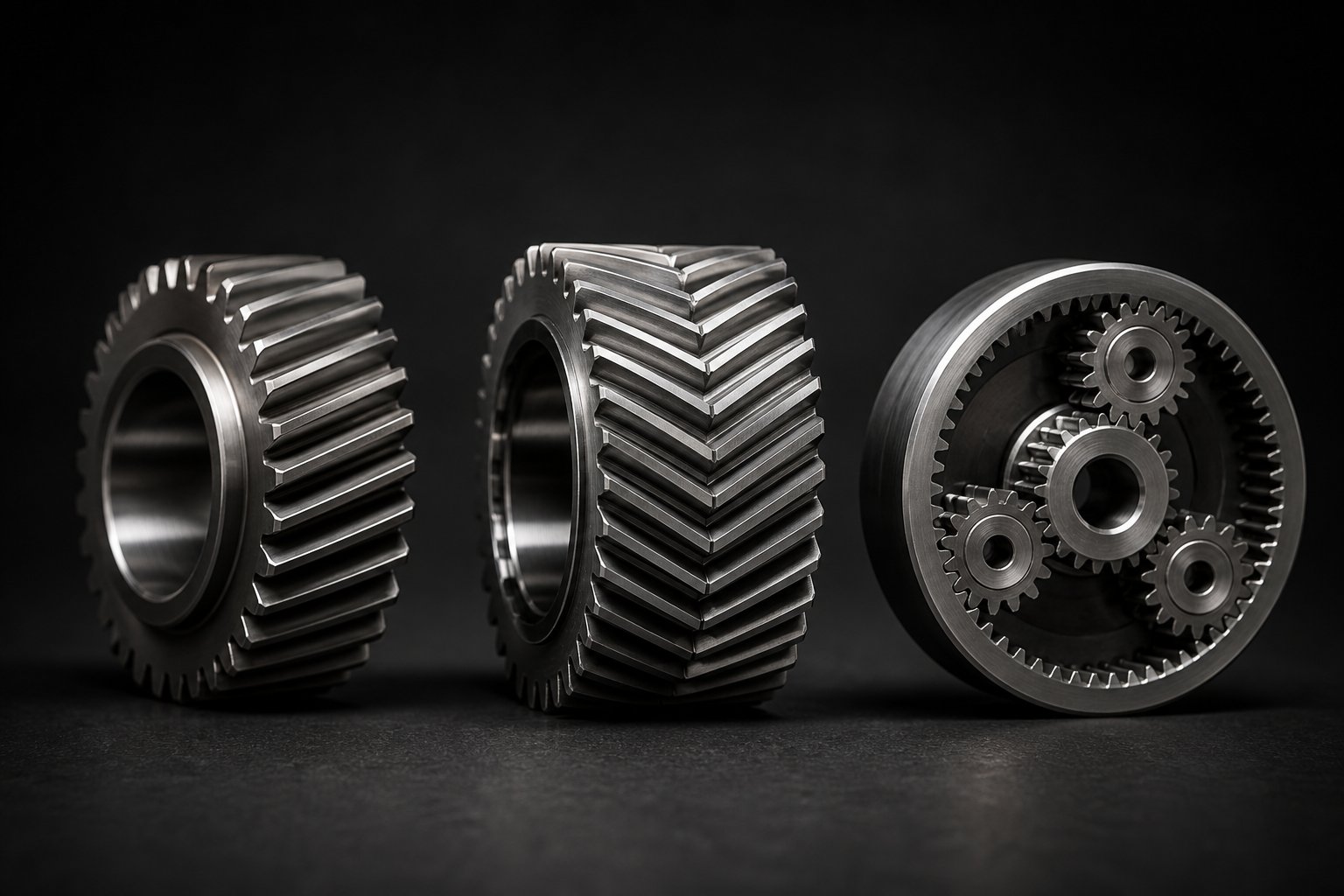
If you opened up ten twin screw extruder gearboxes at random, you would find helical gears in nearly all of them. There are good engineering reasons for this dominance. Helical gears in a twin screw extruder gearbox deliver a combination of characteristics that align almost perfectly with extrusion demands: smooth, progressive tooth engagement, high load capacity relative to their size, relatively quiet operation, and the ability to sustain continuous-duty loading for tens of thousands of hours without fatigue failure.
How does this work mechanically? Unlike spur gears, where teeth engage across their entire face width simultaneously—producing impact loads and audible noise—helical gear teeth make contact along an angled line that sweeps gradually across the tooth face. This progressive engagement means multiple teeth share the load at any instant, reducing peak stress concentrations on individual teeth and smoothing out the torque transmission. The result is lower vibration, reduced noise, and a more uniform power delivery to the extruder screws.
Helix angle selection is where the engineering judgment comes in. A steeper helix angle—say 25 to 30 degrees—increases the contact ratio and produces smoother, quieter operation. But steeper angles also generate larger axial thrust forces within the gearbox itself, entirely separate from the screw-generated thrust the bearing system must already absorb. In a twin screw extruder gearbox where space for thrust bearings is already severely constrained, adding substantial gear-generated axial loads is a significant design burden. Most designs therefore settle on moderate helix angles in the 15 to 25 degree range, striking a balance between smooth engagement and manageable internal thrust. This compromise keeps bearing arrangements simpler and avoids compounding the already-challenging axial load problem.
The continuous-duty performance of helical gears also matters for extrusion. Twin screw extruders often run 24 hours a day, seven days a week, for months between shutdowns. Helical gear tooth profiles can be optimized with tip relief and crowning modifications that accommodate thermal expansion, slight misalignments, and elastic deflections under load—all of which change subtly over extended operating periods. This tolerance for real-world imperfection is one reason helical gears remain the default choice even as manufacturing technology makes more exotic geometries increasingly practical.
Herringbone and Double-Helical Alternatives
Imagine you could keep all the smooth-engagement advantages of helical gears but eliminate the axial thrust they produce. That is exactly what herringbone and double-helical gears accomplish—and it is why they are worth serious consideration in high-power twin screw extruder gearbox design, even though they come at a premium.
A double-helical gear features two sets of helical teeth with opposing helix angles arranged in a V-pattern on the same gear body. One set is cut left-hand, the other right-hand, with a central gap between them for manufacturing tool clearance. A herringbone gear achieves the same geometry but with continuous teeth and no gap, forming an uninterrupted V-pattern. Both designs create a fundamental mechanical advantage: the axial thrust forces generated by each helical section act in opposite directions and cancel each other out, potentially reducing axial bearing loads by approximately 80% compared to single-helical designs.
The herringbone vs helical gears extruder gearbox trade-off centers on three factors. First, thrust elimination simplifies bearing arrangements considerably. In a twin screw gearbox where output shaft bearings are already fighting for space within tight center distances, removing gear-generated axial loads from the equation frees bearing capacity exclusively for screw thrust absorption. Second, double-helical gears allow designers to use steeper helix angles—typically 30 to 45 degrees—without the thrust penalty. Steeper angles mean higher contact ratios, often exceeding 2.0, which translates to at least two tooth pairs in contact at all times. The engagement is smoother, the noise is lower, and the load distribution across the tooth face is more uniform.
The third factor is cost—and it is significant. Double-helical gears demand complex machining processes, often requiring two setups or specialized equipment. The central gap must provide clearance for the hobbing cutter or grinding wheel, and apex point position must be controlled within plus or minus 100 micrometers to prevent unbalanced loading between the two helical sections. Herringbone gears without a gap require even more specialized manufacturing: gear shaping or 5-axis CNC milling, since the continuous V-pattern leaves no room for a conventional hob to run out. High-precision applications demand grinding to achieve AGMA quality grades of 10 to 13, adding another layer of manufacturing complexity and expense.
When does this investment make sense for extruder gearboxes? Primarily in high-power applications where the gearbox transmits substantial torque and the bearing envelope is critically constrained. Double helical gears hold the highest load capacity among parallel shaft gears, and their thrust-neutral behavior is particularly valuable in large twin screw compounding lines where every kilonewton of bearing capacity matters. For smaller or cost-sensitive machines, standard helical gears with appropriately sized thrust bearings remain the more practical choice.
Planetary and Epicyclic Gear Stages
Planetary gear stages occupy a different role in twin screw extruder gearbox design. Rather than serving in the torque-splitting section—where two output shafts must be driven at a fixed center distance—planetary stages typically appear as input reduction stages positioned between the motor and the helical torque-splitting gear train. Their advantage in this position is remarkable torque density and compactness.
A planetary gear stage twin screw gearbox design leverages the fundamental mechanical advantage of epicyclic gearing: multiple planet gears mesh simultaneously with a central sun gear and an outer ring gear, distributing load across three to five contact points rather than the single mesh point of a helical gear pair. This load sharing allows a planetary stage to transmit the same torque in a far smaller envelope—or significantly more torque in the same envelope—compared to an equivalent helical stage. The coaxial input-output arrangement also keeps the drivetrain compact, which is valuable in installations where floor space around the extruder is limited.
Efficiency is another advantage. A well-designed planetary stage achieves approximately 95% to 98% efficiency per stage, compared to roughly 90% to 94% per stage for a standard helical reducer. In an extruder gearbox running continuously, that efficiency difference translates into measurably lower power losses—and therefore less heat to manage.
So why not use planetary stages throughout the entire gearbox? Several practical limitations apply. First, planetary stages introduce greater manufacturing complexity—the planet gears, sun gear, ring gear, and planet carrier must all be manufactured and assembled to very tight tolerances to ensure equal load sharing across the planets. Unequal load distribution among planet gears accelerates wear on the overloaded gear and shortens the stage's service life. Second, at the very high speeds typical of co-rotating extruder input shafts, the orbiting planet gears generate substantial centrifugal forces and windage losses. Heat generation at high rotational speeds can become a limiting factor, requiring more aggressive cooling and higher-grade lubricants. Third, planetary stages are inherently coaxial—they do not naturally split torque to two parallel output shafts separated by a fixed center distance. The torque-splitting function still requires a helical or double-helical gear arrangement downstream.
The practical result is a hybrid architecture: planetary input reduction feeding into a helical torque-splitting output section. This combination captures the torque density and efficiency advantages of epicyclic gearing for the speed-reduction function while relying on the proven, space-efficient helical geometry for the geometrically constrained torque-splitting function.
| Parameter | Helical Gears | Herringbone / Double-Helical Gears | Planetary (Epicyclic) Stages |
|---|---|---|---|
| Load Capacity per Unit Volume | Moderate—single mesh point limits torque density relative to gear envelope | High—steeper helix angles and wide face widths without thrust penalty yield the highest load capacity among parallel shaft gears | Very high—multiple planet gears share load simultaneously, achieving superior size-to-torque ratio |
| Axial Thrust Generation | Moderate to high—proportional to helix angle; must be absorbed by thrust bearings | Effectively zero—opposing helices cancel axial forces, reducing axial bearing loads by ~80% | None—coaxial geometry produces no axial thrust from the gear mesh |
| Noise Level | Low to moderate—progressive tooth engagement reduces impact noise versus spur gears | Low—higher contact ratios (exceeding 2.0) produce smoother, quieter engagement | Low—balanced internal forces and multiple simultaneous mesh points reduce vibration |
| Manufacturing Cost | Low to moderate—standard hobbing, shaping, and grinding processes; widely available | High—requires two machining setups, specialized tooling, and apex position control within ±100 µm | Moderate to high—multiple precision components (sun, planets, ring, carrier) with tight tolerances |
| Maintenance Complexity | Low—straightforward inspection and replacement of individual gear pairs | Moderate—requires specialized measurement for helix alignment and apex verification | Moderate to high—planet gear replacement requires disassembly of the carrier assembly; load sharing must be verified |
| Per-Stage Efficiency | ~90%–94% | ~90%–95% (efficiency gain from eliminated thrust bearing friction) | ~95%–98% |
| Best-Fit Role in Twin Screw Extruder Gearbox | Torque-splitting output stages and intermediate reduction stages—dominant across all extruder sizes | High-power torque-splitting stages where thrust elimination and maximum load capacity justify cost | Input reduction stages where compactness and high torque density are needed before the torque-splitting section |
This comparison reveals an important pattern: no single gear type is universally superior. Helical gears earn their dominance through versatility, cost-effectiveness, and proven reliability across the widest range of extruder sizes and applications. Double-helical and herringbone gears justify their premium in high-power machines where bearing space is critically limited and every reduction in internal thrust translates to a tangible gain in gearbox capacity or service life. Planetary stages bring unmatched torque density to the input reduction function but cannot replace the helical or double-helical geometry required at the torque-splitting output end.
Selecting the right gear types sets the stage for how forces flow through the gearbox. But gears only transmit those forces—the bearings are what ultimately support them, absorb the axial thrust from the screws, and maintain the precise shaft positions that keep the entire gear train functioning within its design tolerances.
Bearing Selection and Axial Load Management in Tight Spaces
Gears define how forces flow through a twin screw extruder gearbox. Bearings determine whether those forces are absorbed gracefully or destructively. And yet, bearing selection is consistently the most underappreciated—and most frequently miscalculated—aspect of the entire design process. The challenge is deceptively simple to state: support two output shafts under extreme axial loads from the extruder screws, absorb high radial loads from gear mesh forces, and do both within a center distance so tight that conventional bearing envelopes simply won't fit. In practice, this three-way collision of load, space, and precision is where more gearbox failures originate than from any gear tooth issue.
Thrust Bearing Configurations for Axial Load Management
Every revolution of an extruder screw pushes molten polymer toward the die, and the die pushes back. That reaction force travels straight through the screw, into the output shaft, and lands squarely on the thrust bearings inside the gearbox. The thrust bearing configuration in a twin screw extruder gearbox must absorb these forces continuously—often for months between maintenance windows—without allowing the shaft to creep axially. Even a fraction of a millimeter of axial displacement shifts gear mesh alignment, accelerates tooth wear, and degrades the torque-splitting accuracy the gearbox was engineered to maintain.
Several bearing types compete for this critical position, and each brings distinct advantages depending on speed, load magnitude, and available space:
Tandem angular contact ball bearings are a common choice for co-rotating extruders where speeds are high and axial loads are moderate. In a tandem (DT) arrangement, two or more angular contact bearings are stacked with their contact angles pointing in the same direction, distributing the axial load equally between them. This configuration effectively multiplies the thrust capacity of a single bearing by the number of stacked units. Higher contact angles—typically 40 degrees for gearbox and compressor applications—favor thrust load capacity over radial support, making them well suited for absorbing screw-generated back pressure. However, tandem arrangements only handle axial loads in one direction. If reverse thrust is possible during startup or process upsets, a third bearing oriented in the opposing direction must be added.
Tapered roller bearings in back-to-back (DB) or face-to-face (DF) arrangements handle combined radial and axial loads simultaneously, which makes them attractive for extruder gearbox output shafts subjected to both gear mesh forces and screw thrust. Back-to-back mounting spreads the effective load centers outward, providing high moment load capacity and excellent rigidity—critical for keeping shaft deflection under control. Face-to-face mounting converges the load centers, offering lower rigidity but greater tolerance for misalignment between shaft and housing. The angular contact vs tapered roller bearings extruder gearbox decision often comes down to speed: tapered rollers generate more friction at high RPM than angular contact ball bearings, producing additional heat that compounds the gearbox thermal management challenge.
Spherical roller thrust bearings (SRTBs) have emerged as an increasingly compelling alternative. These are the only true roller thrust bearings designed to handle heavy axial loads in combination with radial loads while also accommodating misalignment of up to three degrees between shaft and housing without degrading performance. New-generation SRTBs feature optimized internal geometry, cleaner bearing steels with fewer inclusions, and improved heat treatment that delivers significantly higher load-carrying capacity than tapered roller or cylindrical roller thrust bearings of the same dimensions. Their internal roller end and flange contact geometry also promotes better lubricant film formation at low speeds—a critical advantage in counter-rotating extruders that operate at relatively slow RPM where oil film breakdown is a persistent risk.
Bearing preload ties all these configurations together. Applying a controlled axial force to the bearing before it sees any external load eliminates internal clearance, increases stiffness, and improves rotational accuracy. But preload is a double-edged sword. Too little, and the shaft floats under varying process loads, causing vibration and erratic gear mesh contact. Too much, and internal friction rises, heat generation climbs, lubricant viscosity drops, and bearing life shortens dramatically. For heavy-load gearbox applications like extruders, moderate to high preload levels are typical—enough to maintain load distribution and reduce wear without pushing operating temperatures beyond the lubricant's effective range. Spherical roller thrust bearings in extruder gearboxes are normally preloaded with springs to ensure a minimum axial load is maintained at all times, preventing the housing washer from shifting under its own weight when the bearing is unloaded.
Radial Support and Combined Load Scenarios
Axial thrust gets most of the attention, but radial loads in a twin screw extruder gearbox are far from trivial. Every gear mesh generates radial forces perpendicular to the shaft axis—forces that depend on the transmitted torque, the gear pressure angle, and the helix angle. On the output shafts, these gear-induced radial loads combine with the axial screw thrust to create complex combined loading scenarios that neither a pure thrust bearing nor a pure radial bearing can handle alone.
Imagine the output shaft as a beam supported at two points by radial bearings, with gear forces pushing sideways at one location and screw thrust pushing axially along the entire shaft length. The bearing span—the distance between those two radial support points—directly controls how much the shaft deflects under load. A longer span reduces deflection at the gear mesh point, keeping teeth in proper alignment and preserving the involute contact pattern the gears were designed to operate on. A shorter span increases deflection, causing the gear teeth to load unevenly across their face width. That uneven loading concentrates stress at the tooth edges, accelerating micropitting and eventual fatigue failure.
In twin screw gearboxes, the bearing span is constrained by the same center distance limitation that constrains everything else. Engineers cannot simply move the radial bearings farther apart because the housing geometry, adjacent output shaft, and thrust bearing stack all compete for the same axial length. The result is a careful optimization: maximizing the bearing span within the available housing envelope while selecting radial bearings with sufficient stiffness to limit deflection below the threshold where gear mesh accuracy degrades. Cylindrical roller bearings are frequently used for radial support due to their high radial load capacity per unit width and their ability to accommodate slight axial shaft movement without generating internal thrust forces.
In twin-screw arrangements specifically, bearing stiffness takes on heightened importance. The two intermeshing screws must be precisely controlled to prevent contact during operation, which can result in costly damage. One output shaft is typically equipped with a standard thrust bearing arrangement, while the other—constrained by tighter space—uses a multi-step thrust bearing configuration. These two arrangements differ in axial stiffness, and that difference must be accounted for during the design phase to ensure both screws maintain consistent relative positioning under load.
Space Constraints and Bearing Arrangement Innovation
Here is the central paradox of axial load bearing selection for an extruder gearbox: the bearings need to be large to handle the loads, but the space available demands they be small. The tight center distance between output shafts—fixed by screw geometry and the intermeshing zone—severely limits the outer diameter of any bearing that can physically fit around each shaft. In a typical parallel twin screw gearbox, you might have only 20 to 40 millimeters of radial space between the shaft surface and the housing wall shared with the adjacent shaft. Fitting a thrust bearing with adequate dynamic load rating into that envelope requires creative engineering rather than brute-force oversizing.
How do engineers maximize bearing capacity within these minimal dimensions? Several proven strategies have evolved:
- Optimized bearing materials: Newer spherical roller thrust bearings use high-quality steel with minimal inclusions combined with special heat treatment processes that improve wear resistance and extend fatigue life. Cleaner steels mean fewer internal stress concentrators, allowing a smaller bearing to carry loads that previously required a larger one.
- Specialized cage designs: Machined brass cages withstand the high temperatures and heavy loads typical of extruder gearboxes, while engineered polymer cages like PEEK reduce friction and weight in high-speed positions. The cage design directly affects how evenly rollers distribute within the bearing, influencing load capacity and heat generation within the same external dimensions.
- Precision tolerances: Tighter manufacturing tolerances on raceways, rollers, and shaft fits improve load distribution uniformity across all rolling elements. When every roller carries its proportional share of the load rather than a few rollers bearing a disproportionate fraction, the effective dynamic capacity of the bearing increases—without increasing its physical size.
- Innovative stacking arrangements: Multiple smaller bearings arranged in tandem or in hybrid configurations—combining, for instance, a spherical roller thrust bearing for axial load with flanking cylindrical roller bearings for radial support—allow engineers to decompose the combined load into separate components, each handled by the bearing type best suited for that load direction.
- Downsizing through higher-capacity designs: As bearing manufacturers have demonstrated, gearbox OEMs can replace standard tapered roller or cylindrical roller thrust bearings with smaller spherical roller thrust bearings that match or exceed the original load-carrying capacity—reducing overall machine dimensions, energy consumption, and weight without sacrificing reliability.
- Thermal insulation at bearing positions: Operating temperatures at bearing locations in extruder gearboxes typically reach 50 to 60 degrees Celsius, but heat conducted from the extrusion barrel can push temperatures higher. Insulation barriers between the barrel and gearbox housing protect thrust bearings from thermal degradation that would otherwise reduce lubricant film thickness and accelerate wear.
Lubricant selection intersects directly with bearing arrangement decisions. Viscosities in twin screw extruder gearboxes normally range from 320 to 460 cSt, chosen to maintain adequate film thickness at the low rotational speeds and high loads characteristic of output shaft bearings. Spherical roller thrust bearings offer an additional advantage here: their internal geometry generates a natural pumping action during rotation, which improves oil distribution to surrounding gearbox components and helps maintain lubrication at adjacent gear meshes and radial bearings.
The bearing arrangement ultimately defines the continuous-duty capability of the gearbox more directly than many engineers realize. A gearbox with perfectly designed gears but undersized or poorly arranged bearings will fail prematurely—not through dramatic tooth breakage, but through gradual shaft displacement, progressive misalignment, and the slow degradation of every precision interface the bearings were supposed to protect. Getting the bearing arrangement right is what transforms a collection of well-designed gears into a functioning, durable power transmission system.
Bearing performance, in turn, is inseparable from the thermal environment those bearings operate in. Every watt of friction loss in a bearing becomes heat, and every degree of temperature rise changes the lubricant film that keeps the bearing alive. This connection between mechanical efficiency and thermal behavior is the next critical link in the design chain.
Gearbox Efficiency and Thermal Management Strategies
Every bearing friction point, every gear tooth sliding against its mating surface, every liter of oil churning inside the housing—these are all mechanisms converting useful mechanical power into heat. In a twin screw extruder gearbox, that heat is not merely a byproduct. It is the single most persistent threat to lubricant integrity, dimensional stability, and long-term bearing life. Understanding twin screw extruder gearbox power loss sources is the first step toward controlling them. Managing the thermal consequences of those losses is what separates a gearbox rated for continuous heavy-duty service from one that drifts toward premature failure under sustained load.
Sources of Power Loss in Extruder Gearboxes
Where does the power go? In any multi-stage gearbox, losses divide into load-dependent and load-independent categories, and both matter significantly at the operating conditions typical of twin screw extrusion.
Gear mesh friction is the largest load-dependent loss. As two helical gear teeth engage, they do not roll purely against each other—there is always a sliding component, and that sliding generates friction. The magnitude depends on the gear type, helix angle, surface finish, contact ratio, and the lubricant film separating the tooth surfaces. Research into automotive and industrial gearbox efficiency using ISO/TR 14179 calculation methods shows that gear mesh losses can be meaningfully reduced through optimized microgeometry—profile modifications and tooth trace corrections that redistribute meshing forces and minimize sliding velocity at the contact points. In one documented case, contact ratio optimization from 2.0 to 1.5 reduced gear meshing losses by 28 watts per stage, though the resulting increase in helix angle added roughly 5 watts of bearing loss from higher axial forces. Every optimization, in other words, triggers a trade-off somewhere else in the system.
Bearing friction contributes both load-dependent and load-independent losses. Rolling element bearings generate friction from the elastic deformation of rollers against raceways (load-dependent) and from lubricant shear, cage drag, and seal contact (load-independent). In twin screw extruder gearboxes, the output shaft bearings—heavily loaded with both radial gear forces and axial screw thrust—represent the most significant bearing loss locations. Tapered roller bearings, while excellent for combined loads, generate higher friction at elevated speeds than angular contact ball bearings, which is one reason bearing type selection feeds directly into the thermal management equation.
Oil churning and windage losses are the dominant speed-dependent losses and become especially significant in co-rotating extruder gearboxes operating at high input shaft speeds. As gears rotate, they plunge into the oil sump and fling lubricant against the housing walls. The energy spent accelerating and shearing that oil is pure waste—it contributes nothing to power transmission but generates substantial heat. Calculation methods based on ISO/TR 14179-2 address injection lubrication losses specifically, quantifying the power consumed by oil directed at gear tooth contacts and bearing positions. At higher rotational speeds, churning losses climb progressively, which is why efficiency maps for gearboxes consistently show declining efficiency at high speed and low torque—the speed-dependent losses remain constant while the useful power output drops.
Seal friction is often overlooked but never absent. Radial shaft sealing rings on the input and output shafts generate constant drag losses that are independent of transmitted torque. In a gearbox with multiple shaft exits, the cumulative seal loss is a non-trivial contributor to overall heat generation.
How do these losses add up? Well-designed helical gear stages achieve per-stage efficiencies in the range of 90% to 98%, depending on gear type, speed, load, and lubrication quality. A three-stage gearbox with 96% efficiency per stage delivers approximately 88.5% overall efficiency. For a 300 kW extruder drive, that means roughly 34.5 kW of continuous heat generation inside the gearbox housing—equivalent to running dozens of space heaters in an enclosed metal box. Over thousands of operating hours, the energy cost of gearbox mechanical efficiency losses in extrusion applications accumulates into a significant fraction of total operating expense. And all of that lost energy must go somewhere—which is why the thermal management system becomes the gatekeeper of continuous performance.
Thermal Management and Cooling Systems
Heat does not simply make a gearbox warm. It degrades every precision interface inside it. Rising temperatures reduce lubricant viscosity, thinning the protective oil films between gear teeth and bearing surfaces. Thermal expansion shifts gear mesh alignment by micrometers—enough to change contact patterns and concentrate stress at tooth edges. Bearing internal clearances change as inner rings, outer rings, and rolling elements expand at different rates, altering preload conditions that were carefully set during assembly. Left uncontrolled, heat turns a well-engineered gearbox into a slowly self-destructing machine.
The thermal management cooling system for an extruder gearbox must dissipate all internally generated heat fast enough to maintain a stable equilibrium temperature—one where the lubricant retains its protective viscosity and thermal expansion remains within the tolerances the gear train was designed to accommodate. Three cooling strategies cover the range of extruder sizes and power levels:
Natural convection works for smaller gearboxes with modest power losses. Heat conducts through the gear housing walls and dissipates into the surrounding air. Housing surface area, fin design, and ambient temperature determine the cooling capacity. This approach is simple and maintenance-free, but its thermal ceiling is low. For extruder gearboxes above roughly 30 to 50 kW input power, natural convection alone cannot maintain acceptable oil temperatures under continuous load.
Forced-air cooling extends the thermal envelope by mounting a shaft-driven or electric fan on the gearbox housing. The moving air increases the convective heat transfer coefficient at the housing surface, typically doubling or tripling the heat dissipation rate compared to still air. Many mid-range twin screw extruder gearboxes use this approach because it adds minimal cost and complexity while significantly raising the continuous torque rating. The thermal rating calculation methods in ISO/TR 14179 specifically address heat dissipation through the housing surface, rotating parts like shafts and couplings, and the base—all of which benefit from forced airflow.
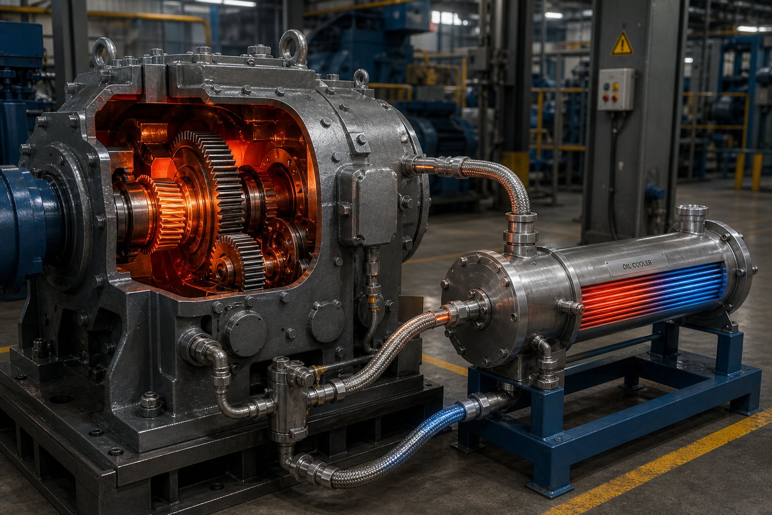
Oil circulation systems with external heat exchangers are the standard for high-power applications. Rather than relying on the housing to reject heat, these systems pump oil out of the gearbox sump, through an external cooler—typically a shell-and-tube heat exchanger using water or air as the cooling medium—and back into the gearbox at a controlled temperature. This approach decouples the gearbox's thermal capacity from its physical housing size, allowing compact, high-torque-density designs that would overheat within minutes under natural convection alone. The external heat exchanger can reject tens of kilowatts of thermal energy, and the circulating oil also serves double duty: it flushes wear particles away from gear meshes and bearing contacts, delivers fresh lubricant to critical interfaces, and equalizes temperature gradients that would otherwise cause uneven thermal expansion across the housing. As industrial cooling engineers emphasize, if gearbox oil runs too hot, viscosity drops, lubrication films thin out, and internal components can suffer accelerated wear or even catastrophic failure.
Lubricant Selection and Oil System Design
The lubricant inside a twin screw extruder gearbox is not a passive fluid—it is an active engineering component whose properties directly shape both efficiency and thermal behavior. Lubricant viscosity selection for extruder gearbox efficiency involves a fundamental balancing act: the oil must be thick enough to maintain protective films between gear teeth and bearing rolling elements, yet thin enough to minimize the churning and shearing losses that generate the very heat threatening those films.
Industrial gear oils for extruder gearboxes typically fall within the ISO VG 320 to ISO VG 460 viscosity grade range. Higher viscosity provides thicker films and better protection under heavy loads and low speeds—conditions typical of output shaft bearings in twin screw gearboxes. But higher viscosity also means greater resistance to flow, which increases churning losses at the input stages running at higher speeds. The practical consequence? A gearbox running ISO VG 460 oil may dissipate noticeably more heat at its high-speed input stage than the same gearbox running ISO VG 320, even though the heavier oil provides superior protection at the slow-turning, heavily loaded output end.
Lubricant chemistry matters as much as viscosity grade. Research presented at AGMA technical meetings demonstrates that synthetic gear oils formulated with low-traction base fluids can improve gearbox efficiency by up to 8% compared to mineral-oil-based lubricants of the same viscosity grade—and reduce equilibrium operating temperatures by as much as 12 degrees Celsius under high-torque conditions. These gains stem from inherent differences in molecular structure: synthetic base fluids with lower traction coefficients resist internal shearing more easily, converting less mechanical energy into frictional heat at every gear mesh and bearing contact. The additive package also plays a role—anti-wear and extreme-pressure additives must protect surfaces without increasing boundary friction, while oxidation inhibitors preserve viscosity stability over extended drain intervals.
Filtration is the often-neglected companion to lubricant selection. Precision-ground gear tooth surfaces and bearing raceways are vulnerable to abrasive damage from metallic wear particles, ingested contaminants, and oxidation byproducts circulating in the oil. A properly designed oil system includes full-flow filtration—typically rated at 10 to 25 micrometers for industrial gear applications—that continuously removes particles before they can score gear flanks or embed in bearing surfaces. In high-power gearboxes with external oil circulation systems, the filter is positioned in the return line between the gearbox drain and the external cooler, catching debris before it passes through the heat exchanger and re-enters the gearbox. Oil condition monitoring—tracking particle counts, water contamination, viscosity changes, and acid number—provides early warning of internal wear or lubricant degradation long before vibration or temperature alarms signal a problem.
In many twin screw extruder gearboxes, thermal management—not gear tooth strength—determines the continuous torque rating. A gear train capable of transmitting 5,000 Nm may be limited to 3,500 Nm in continuous service because the cooling system cannot dissipate the heat generated at full load without exceeding the lubricant's maximum operating temperature.
This thermal ceiling is why experienced gearbox engineers size cooling systems before finalizing gear geometry—not after. The most elegant torque-splitting arrangement and the most precisely ground gear teeth are irrelevant if the gearbox cannot run at rated torque for 8,000 hours per year without overheating. Efficiency, thermal management, and lubricant selection form a tightly coupled triad, and optimizing any one element in isolation almost always creates problems in the other two.
Quantifying these interrelationships—and validating that a proposed design can actually meet its performance targets—requires standardized methods for rating gear capacity, calculating safety factors, and simulating real-world operating conditions before the first gear blank is ever cut.
Performance Standards and Modern Design Validation Methods
How do you actually prove that a twin screw extruder gearbox design on paper will survive decades of continuous service? Intuition and experience help, but they are not enough. The gap between a promising gear arrangement sketch and a validated production gearbox is bridged by two things: standardized performance metrics that allow apples-to-apples comparison, and rigorous analytical methods that predict real-world behavior before metal is ever cut. Torque density defines what the gearbox must achieve. Industry standards define how to calculate whether the gears can handle it. Simulation tools reveal what the standards alone cannot see. Together, they form the validation framework that separates reliable gearboxes from expensive failures.
Torque Density as a Key Performance Metric
If you could distill the entire performance ambition of a modern twin screw extruder gearbox into a single number, it would be torque density. Measured in Nm/cm³, this metric expresses the torque output relative to the screw cross-sectional area the gearbox drives. It captures, in one figure, how effectively the gearbox converts its physical volume into useful processing capability. A higher torque density twin screw extruder gearbox benchmark means more throughput, more intensive mixing, and the ability to process higher-viscosity or heavily filled materials—all within the same machine footprint.
Why does this matter so much right now? Extruder OEMs are under relentless pressure to increase throughput without enlarging machine platforms. Plant floor space is expensive. Installation footprints are fixed. Customers want 30% more output from the same frame size they purchased a decade ago. The gearbox is where that ambition either succeeds or hits a wall. Modern high-performance twin screw extruders have pushed torque densities to 18 Nm/cm³, a 30% leap over previous generations that opened up processing of materials—glass-filled polyamides, glass-reinforced polypropylene, and other demanding compounds—that were previously torque-limited.
To put the range in practical context: standard production machines typically operate between 5 and 10 Nm/cm³. High-torque machines exceed 10 Nm/cm³. The elite tier—machines targeting advanced compounding and reactive extrusion—targets 15 to 18 Nm/cm³, with some manufacturers pushing toward even higher values. A high-torque extruder gearbox at 18 Nm/cm³ can enable up to a 100% increase in throughput rate for torque-limited materials compared to an older machine at 10 Nm/cm³. That is not an incremental improvement—it is a generational shift in processing capability.
So what are the engineering levers for improving torque density in extruder gearbox design? Several factors work in combination:
- Better gear materials: Higher-grade alloy steels with tighter control over inclusions and grain structure allow tooth roots and flanks to withstand greater bending and contact stresses. The relationship between material hardness and allowable stress is well characterized—research published through AGMA demonstrates that both bending and pitting allowable stress numbers can be systematically derived from surface hardness values, confirming that material selection directly governs the stress ceiling a gear tooth can sustain.
- Advanced heat treatment and surface finishing: Case carburizing, nitriding, and precision induction hardening create a hard, fatigue-resistant surface layer over a tough core. Superfinishing techniques that reduce tooth surface roughness to sub-micron levels improve lubricant film formation, reduce friction-generated heat, and extend the pitting fatigue life of the flank. These treatments allow engineers to push contact stresses closer to the material's theoretical limits without premature surface failure.
- Optimized gear tooth profiles: Microgeometry modifications—tip relief, root relief, lead crowning, and profile slope corrections—redistribute load across the tooth surface, reducing peak stresses that would otherwise limit the gearbox's torque rating. These modifications also compensate for elastic deflections and thermal expansion under operating conditions, ensuring the theoretical contact pattern matches reality.
- Higher-precision manufacturing: Tighter tolerances on gear tooth geometry reduce transmission error, improve load sharing between teeth, and minimize dynamic overloads. As gear accuracy class improves, the gap between theoretical stress calculations and actual operating stresses narrows, giving engineers more confidence to design closer to material limits.
- Screw geometry optimization: A Do/Di ratio (outer to inner screw diameter) of 1.55 has emerged as the balance point for high-torque applications, maximizing the cross-sectional area available for torque transmission while maintaining adequate channel depth for material processing.
Each of these levers interacts with the others. Superfinished tooth surfaces lose their advantage if the gear steel contains too many inclusions. A perfectly optimized tooth profile cannot compensate for a heat treatment that leaves residual stress concentrations at the case-core boundary. Improving torque density in extruder gearbox design is fundamentally a systems-level optimization—not a single-variable exercise.
Industry Standards Governing Gearbox Design
Engineering intuition can suggest whether a gearbox design is reasonable. Standards provide the rigorous, repeatable methods to prove it. Three major frameworks govern gear load capacity calculations worldwide, and understanding what each one does—and does not—cover is essential for anyone specifying, designing, or evaluating a twin screw extruder gearbox.
ISO 6336 is the international standard for calculating the load capacity of cylindrical involute gears. It provides systematic methods for evaluating two primary failure modes: tooth root bending fatigue and tooth flank contact fatigue (macropitting). The standard calculates the effective bending stress at the tooth root fillet and the Hertzian contact pressure on the tooth flank, then compares each to allowable stress values determined by the gear material, heat treatment, surface hardness, and desired reliability level. ISO 6336-5 specifically provides databases of bending and pitting allowable stress numbers for various steels and cast irons, evaluated at 1% probability of failure—meaning 99 out of 100 gears meeting these criteria will survive the specified number of load cycles. Safety factors are then applied to account for application-specific loading conditions, service factors, and design confidence requirements.
AGMA standards (particularly AGMA 2101, the metric edition of the gear rating standard) follow a parallel methodology but originate from the American Gear Manufacturers Association and reflect North American engineering practice. AGMA standards define reliability factors, overload factors, and dynamic factors that adjust the calculated stress to reflect real operating conditions—including the transient torque spikes during cold startup that can exceed steady-state running torque by 20% to 40%. The AGMA service factor, in particular, is critical for extruder applications: it accounts for the loading character of the driven machine and must cover these transient peaks, not just steady-state conditions. Treating it as optional padding, as some engineers do, leads directly to undersized gearboxes that limit production capacity.
DIN 3990, the German standard, predates the current ISO 6336 and shares much of its theoretical foundation. It remains commonly referenced by European gearbox manufacturers, and many proprietary design tools still implement DIN 3990 calculation methods internally. The differences between DIN and ISO are primarily in specific factor definitions and calculation sequences rather than fundamental methodology—but those differences can produce slightly different safety factor results for the same gear geometry, which is why specifying which standard governs a particular gearbox design is essential during procurement.
What all three AGMA ISO 6336 gearbox gear rating standards share is a common analytical structure: they calculate the actual applied stress from the gear geometry, transmitted load, and operating conditions, then compare it to the permissible stress determined by material properties, quality grade, and statistical reliability targets. The ratio of permissible to actual stress gives the safety factor. For extruder gearboxes expected to run continuously for years, minimum safety factors of 1.3 to 1.5 for bending and 1.0 to 1.2 for contact are typical targets—but the specific values depend on the consequence of failure, the accuracy of load data, and the confidence in material quality.
A critical subtlety that many specification documents miss: these standards calculate gear tooth capacity, not gearbox capacity. The gearbox's continuous torque rating is the lower of the gear tooth capacity, the bearing life capacity, and the thermal dissipation capacity. As the previous chapter established, thermal limits frequently govern before gear teeth reach their rated stress—which is why a standards-compliant gear calculation alone does not guarantee a gearbox will perform as expected in service.
Simulation-Driven Design Validation
Standards provide the calculation backbone. But twin screw extruder gearboxes operate under conditions—tight center distances, complex combined loading, thermal gradients, housing deflections—that push beyond the idealized assumptions embedded in standards-based calculations. This is where FEA simulation for gearbox gear contact stress analysis and broader computational tools earn their place in the design process.
Modern CAD and finite element analysis (FEA) tools allow engineers to evaluate aspects of gearbox behavior that analytical standards either simplify or ignore entirely. Extensive research into gear stiffness calculation methodologies has produced a hierarchy of simulation approaches—from fast analytical slice methods used in early sizing through high-fidelity hybrid finite element methods that capture tooth deflection, contact pressure distribution, and rim stiffness simultaneously. The key simulation domains for extruder gearbox validation include:
- Gear contact stress analysis: FEA calculates the Hertzian contact pressure distribution across the tooth flank under actual operating loads, including the effects of misalignment, microgeometry modifications, and elastic deflection. Unlike the standards-based approach, which uses simplified geometric models, FEA reveals whether stress concentrations exist at tooth edges due to insufficient crowning or at root transitions due to improper fillet geometry.
- Tooth bending stress simulation: Finite element models of the tooth root fillet capture the actual stress gradient through the case-hardened surface layer and into the softer core material—a detail that analytical methods approximate with correction factors but cannot resolve spatially.
- Housing stiffness evaluation: The gearbox housing is not infinitely rigid. Under heavy torque and thrust loads, it deflects—and that deflection shifts bearing positions relative to each other, changing gear mesh alignment. FEA of the housing under operational loads quantifies these deflections so that bearing bore positions can be compensated during manufacturing.
- Thermal deformation prediction: Temperature gradients between the housing exterior (exposed to ambient air or cooling systems) and the interior (bathed in hot oil near gear meshes) cause differential expansion that distorts the housing. Coupled thermal-structural FEA predicts these deformations and their effect on gear center distances and bearing fits.
- Dynamic load analysis: Gear mesh stiffness varies cyclically as teeth enter and leave contact, creating excitation forces at mesh frequency and its harmonics. Dynamic simulation—whether through lumped-parameter torsional models or full multibody dynamics—predicts vibration levels, identifies resonance risks, and guides microgeometry optimization to minimize transmission error, which correlates directly with gear noise.
How do computational tools complement—but not replace—standards-based calculations? Think of standards as the legal framework and simulation as the engineering investigation. Standards establish the minimum acceptable safety factors and provide the industry-agreed methodology for gear rating. Simulation reveals why a particular design meets or fails those standards under real-world conditions, and—critically—it uncovers failure modes that standards do not explicitly address: housing-induced misalignment, thermal distortion, dynamic overloads at resonance, and the subtle interactions between gear mesh stiffness and system-level deflections. Research into gear system analysis workflows emphasizes that the most reliable designs result from coupling the system deflection analysis (which determines misalignment at the gear mesh) with the loaded tooth contact analysis (which determines load distribution on the teeth)—rather than treating them as independent calculations.
The typical design validation sequence for a twin screw extruder gearbox follows a structured progression from rough sizing to physical proof:
- Initial gear sizing: Using standards-based methods (ISO 6336, AGMA 2101, or DIN 3990), engineers select gear module, face width, helix angle, number of teeth, and material grade to meet the required torque and speed at the specified safety factors. This stage produces a preliminary gear arrangement and approximate gearbox envelope.
- Bearing selection and life calculation: Based on the gear forces calculated in step one, engineers select bearing types and sizes for radial and thrust positions. Bearing life calculations (per ISO 281 or equivalent) verify that the selected bearings meet the target service life—typically 20,000 to 50,000 hours minimum—under the combined radial and axial loading conditions.
- System deflection analysis: A finite element or analytical model of the complete shaft-bearing-housing system calculates the deflections and misalignments at each gear mesh under full operating load and thermal conditions. These misalignments are fed into the gear contact analysis to ensure the tooth contact pattern remains acceptable.
- Loaded tooth contact analysis (LTCA): Using the misalignment data from step three, engineers run a detailed contact simulation to evaluate the actual load distribution across the tooth flank, transmission error, and peak stresses. Microgeometry modifications—tip relief, lead crowning, profile slope—are optimized at this stage to ensure uniform load distribution and minimize transmission error across the expected operating torque range.
- Thermal analysis: A thermal model of the gearbox calculates the equilibrium oil temperature under continuous-duty conditions, verifying that the cooling system can dissipate all internally generated heat without exceeding the lubricant's maximum operating temperature. If the thermal analysis reveals an overtemperature condition, the cooling system is upgraded or the continuous torque rating is reduced.
- Dynamic analysis and NVH assessment: Torsional vibration models and, where necessary, full multibody dynamic simulations identify potential resonance conditions, evaluate gear noise (whine) risk, and validate that dynamic loads remain within the safety factor envelope established by the standards-based calculations.
- Prototype testing and correlation: The first physical gearbox undergoes instrumented testing—strain gauges on gear teeth, accelerometers on the housing, temperature sensors at bearing positions, and oil condition monitoring—to correlate measured performance against all analytical and simulation predictions. Discrepancies are investigated, models are refined, and design adjustments are made before series production begins.
Skipping steps in this sequence is where engineers most commonly get it wrong. A gearbox sized purely on standards-based gear calculations (step one) without system deflection analysis (step three) may place gears in mesh under misalignment conditions that double the peak contact stress at one edge of the tooth face. A design validated through contact analysis but without thermal modeling may deliver its rated torque for the first hour—then derate itself as oil temperatures climb beyond the cooling system's capacity. Each validation step catches failure modes that the previous steps either assumed away or could not detect.
The interplay between torque density targets, standards-based safety factors, and simulation-driven refinement creates a design loop that spirals toward an optimized solution. But the targets themselves are not static. New applications, new materials, and new monitoring technologies are reshaping what gearbox designers aim for—and how they verify that their designs will hold up in environments that the original standards frameworks never anticipated.
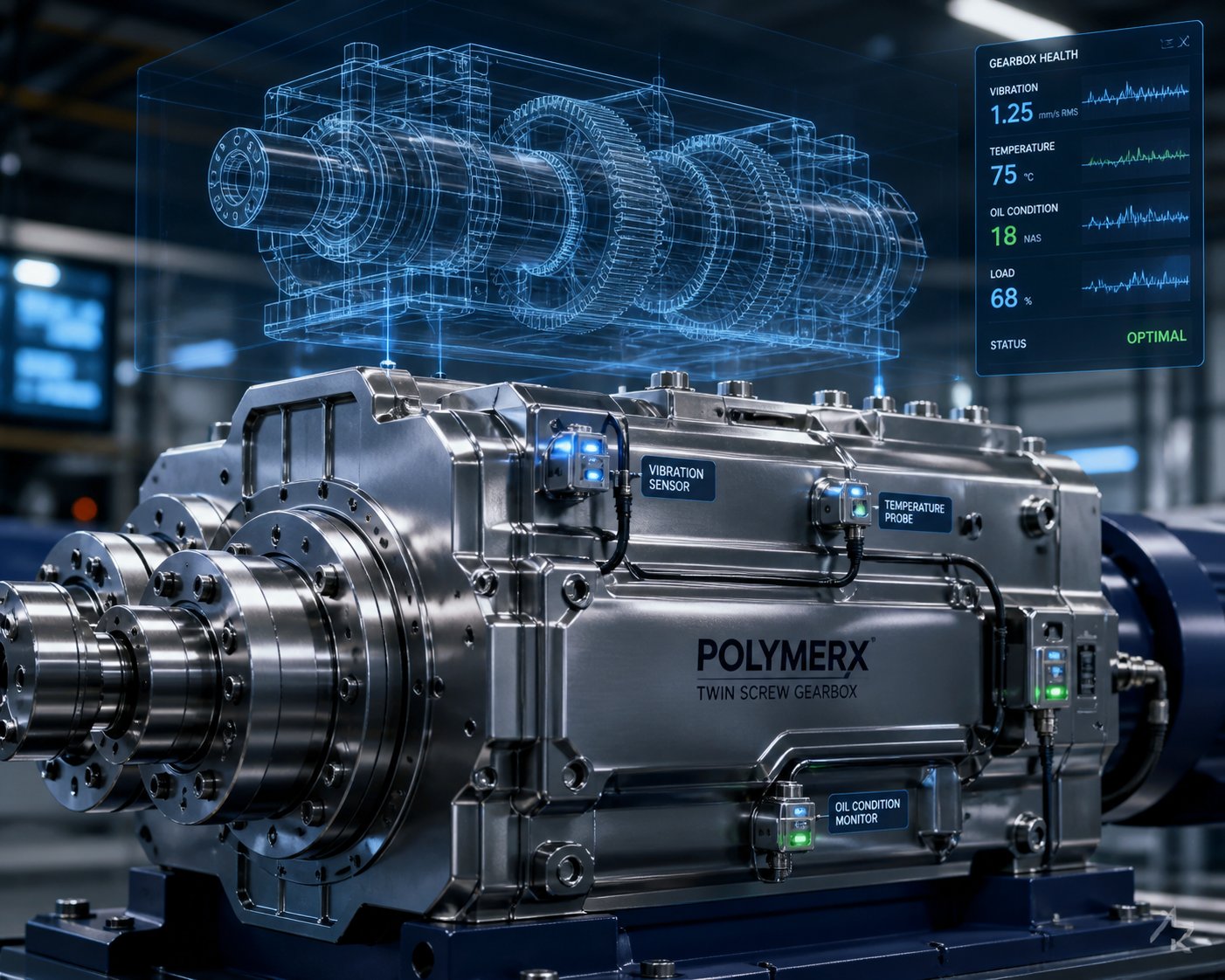
Emerging Trends Shaping the Future of Extruder Gearbox Design
Standards and simulation provide the tools to validate today's gearbox designs. But the applications those gearboxes must serve—and the technologies available to build and monitor them—are evolving faster than the standards committees that write the calculation methods. Three intersecting forces are reshaping twin screw extruder gearbox design: entirely new processing applications demanding capabilities beyond traditional plastics extrusion, material science breakthroughs enabling higher performance from smaller gear and bearing envelopes, and digital monitoring systems transforming how gearboxes are maintained in service. Each of these forces is already influencing design decisions on current-generation machines, and their combined trajectory points toward gearboxes that are denser, smarter, and longer-lived than anything available a decade ago.
New Applications Driving Gearbox Innovation
Twin screw extruders are no longer confined to compounding thermoplastics. Some of the most demanding battery electrode compounding twin screw gearbox requirements are emerging from the energy storage industry, where lithium-ion battery manufacturers use twin screw extruders to mix active materials, binders, and conductive additives into uniform electrode slurries. As Thermo Fisher Scientific details, these extruders must achieve precise, homogeneous mixing—any inconsistency in the slurry composition directly impacts battery performance and lifespan. Dry electrode processing and dry binder fibrillation techniques push the torque envelope even further, requiring sustained high shear at controlled temperatures that translate into elevated, sustained gearbox loading far beyond what conventional polymer compounding demands.
Biodegradable polymer processing adds a different challenge. Materials like PLA, PHA, and starch-based blends are thermally sensitive, requiring precise screw speed control across wide ranges to balance mixing intensity against degradation risk. The gearbox must deliver smooth, vibration-free torque across a broader speed window than standard compounding applications require. Advanced composite preparation—incorporating carbon fibers, glass fibers, or natural fibers into polymer matrices—generates extreme torque spikes during fiber wetting and dispersion that stress the gear train well beyond steady-state ratings. These new applications collectively demand gearboxes with higher torque density, wider speed ranges, enhanced transient load tolerance, and tighter thermal control than traditional plastics processing ever required.
Advanced Materials and Surface Treatments
Meeting these escalating demands with the same gear steels and surface treatments used twenty years ago is not feasible. Developments in gear metallurgy and finishing processes are enabling advanced gear steel surface treatment for gearbox longevity improvements that would have seemed unrealistic a generation ago.
On the metallurgical side, higher-cleanliness steels with fewer non-metallic inclusions reduce the internal stress concentrators that initiate fatigue cracks beneath case-hardened surfaces. Tighter control over grain structure during forging and heat treatment produces more uniform case depths and predictable hardness gradients from the surface into the tough core—exactly the combination needed for gears operating at the extreme contact stresses demanded by high-torque-density designs.
Surface finishing is where some of the most measurable gains are being realized. Isotropic superfinishing processes reduce gear tooth roughness to values below Ra 0.1 micrometers while creating a non-directional surface texture. Research documented by Gear Solutions reports that isotropically superfinished spur gears demonstrated approximately 17% higher efficiency compared to standard ground gears in testing conducted by General Motors and The Ohio State University. These smoother surfaces improve lubricant film formation, reduce friction-generated heat, and provide significantly greater resistance to micropitting and scuffing—failure modes that directly limit the contact stress ceiling in extruder gearboxes.
The benefits extend to a systems level. Smoother gear flanks enable the use of lower-viscosity lubricants while maintaining adequate film separation, which reduces churning losses and further improves efficiency. However, as that same research emphasizes, reducing lubricant viscosity introduces risks for the bearings, which often operate at lower contact speeds and higher Hertzian pressures than the gears. Diamond-like carbon (DLC) coatings on bearing surfaces offer a complementary solution—their extremely high hardness and low friction coefficient protect bearings against contact fatigue even when oil film thickness becomes marginal. The combined approach of superfinished gears plus DLC-coated bearings represents a system-level optimization that can be applied to existing gear and bearing designs with minimal geometric change, making it an attractive upgrade path for gearbox manufacturers seeking performance gains without costly redesigns.
Higher-grade bearing steels with advanced heat treatment are following the same trajectory. Cleaner steels, optimized raceway finishes, and specialized coatings collectively extend bearing fatigue life within the same physical envelope—critical for twin screw gearboxes where center distance constraints prevent simply installing larger bearings.
Trends in Gearbox Monitoring and Predictive Maintenance
Building a better gearbox is only half the equation. Knowing what is happening inside it during operation—and predicting what will happen next—is transforming maintenance from a calendar-driven ritual into a data-driven strategy. Predictive maintenance vibration monitoring for extruder gearboxes is moving from a nice-to-have feature to a baseline expectation, driven by the steep costs of unplanned downtime on high-throughput extrusion lines.
Modern gearbox monitoring integrates multiple sensor streams. Accelerometers mounted on the housing capture vibration signatures at gear mesh frequency and its harmonics—signatures that change characteristically as tooth wear, pitting, or cracking develops. Oil condition sensors track particle counts, water contamination, viscosity changes, and ferrous debris concentration in real time, providing chemical and physical evidence of internal wear long before it becomes visible in vibration data. Temperature sensors at bearing positions detect thermal anomalies that signal lubricant film breakdown or bearing preload drift. Together, these streams create a continuous health portrait of the gearbox that enables condition-based maintenance: intervening precisely when evidence warrants it, rather than on a fixed schedule that either replaces components too early (wasting money) or too late (risking catastrophic failure).
Digital twin modeling for extruder gearbox design trends is pushing this capability further. A recent study published in Measurement demonstrates how digital twins built from energy-driven vibrational models can generate synthetic fault signatures—chipped teeth, root cracks, surface wear, missing teeth—that closely replicate real-world sensor data. By combining these simulated signatures with experimentally captured noise through feature mode decomposition, the researchers achieved fault diagnosis accuracy exceeding 95% using a 1D convolutional neural network, even under severe data-scarcity conditions where faulty-state operating data was extremely limited. This approach is particularly relevant for extruder gearboxes, where intentionally running equipment in a faulty state to collect training data is impractical due to the high cost of damage. Digital twins allow predictive models to be trained on virtual fault data and validated against limited real-world measurements, anticipating problems that have never actually occurred on a specific machine.
The convergence of these trends—new applications, advanced materials, and intelligent monitoring—is defining the next generation of twin screw extruder gearbox design. Here are the key developments to watch:
- Higher torque density targets: Battery electrode processing, composite compounding, and biodegradable polymer applications are pushing torque density requirements beyond 18 Nm/cm³, demanding continued advances in gear materials, tooth profile optimization, and bearing capacity within unchanged center distances.
- Integrated condition monitoring: Vibration sensors, oil quality analyzers, and temperature probes are being designed into gearbox housings from the outset rather than retrofitted as aftermarket additions, enabling seamless data collection for predictive maintenance algorithms.
- Advanced materials and surface engineering: Isotropic superfinishing, DLC coatings, higher-cleanliness steels, and next-generation lubricants are being applied as coordinated system-level upgrades rather than isolated component improvements—maximizing efficiency and fatigue life simultaneously.
- Digital twin modeling: Physics-based virtual replicas of gearbox dynamics, coupled with machine learning classifiers, are enabling fault diagnosis under data-scarce conditions and supporting proactive maintenance decisions that minimize unplanned downtime.
- Modular gearbox architectures: Standardized interface dimensions and interchangeable gear stages allow faster customization for new applications without full custom engineering—reducing lead times for OEMs responding to rapidly diversifying end markets.
These trends are not speculative—they are already influencing design decisions on machines being engineered and built today. The gearbox that sits at the heart of a twin screw extruder five years from now will transmit more torque in a smaller package, run cooler and quieter, and communicate its own health status in real time. But none of that matters in isolation. A gearbox, no matter how advanced, operates as one element within a complete extrusion system—and its real-world performance depends entirely on how well it integrates with the motor driving it and the screw elements it powers.
Integrating Gearbox Design Into Your Complete Extruder Strategy
A gearbox does not operate in a vacuum. It sits at the mechanical center of an extrusion system, receiving power from a motor on one side and delivering torque to polymer-processing screws on the other. Every design decision, performance gain, and reliability improvement discussed throughout this article means nothing if the gearbox is treated as an isolated component rather than an interconnected subsystem. The systems engineering approach to a twin screw extruder gearbox demands that engineers look both upstream and downstream—matching the motor's output characteristics to the gearbox's capacity, and ensuring the screw and barrel components downstream do not impose loads the gearbox was never designed to handle.
The Gearbox Within the Complete Extruder System
Think about what the gearbox actually delivers to the screws: a torque curve, a speed range, and a level of torsional stiffness. These three output characteristics directly constrain which screw configurations are viable and what process parameters are achievable. A gearbox with a narrow constant-torque speed range limits the operator's ability to optimize screw speed independently from feed rate—a fundamental requirement in starve-fed co-rotating compounding. A gearbox with insufficient torsional stiffness allows rotational oscillations that propagate into melt pressure fluctuations at the die, degrading product dimensional consistency in ways that no downstream adjustment can correct.
Motor gearbox matching for a twin screw extruder system is equally critical on the upstream side. The motor's power rating, base speed, and operating regions—constant torque below base speed, constant power above it—must align precisely with the gearbox reduction ratio and thermal capacity. A common engineering error is selecting a motor with adequate peak power but a base speed that, after gearbox reduction, places the constant-torque region below the screw speed range actually used in production. The result is a system that cannot deliver full torque at the speeds where the process needs it most. As the formulas documented by Leistritz and Coperion engineers illustrate, shaft torque is directly linked to motor power and maximum RPM—meaning there is no difference in available torque whether you install a 200 kW motor geared for 600 RPM or a 400 kW motor geared for 1,200 RPM, unless the process actually benefits from that higher speed range. Specifying more motor than the gearbox and process require wastes capital without adding capability.
Maintaining Gearbox Integrity Through Quality Components
Here is where many plant teams get it wrong: they invest heavily in a premium gearbox, then allow the surrounding drivetrain components to degrade until those degraded parts destroy the very gearbox they paid to protect. An extruder drivetrain maintenance gearbox protection strategy must extend well beyond oil changes and vibration checks on the gearbox itself.
Consider what happens when screw elements wear. As flight tips erode and clearances between screw and barrel increase, the extruder loses pressure-generation efficiency. To maintain throughput, operators compensate by increasing screw speed—which increases torque demand on the gearbox. Industry maintenance data confirms that for a 75 mm extruder processing filled compounds, screw and barrel components may need replacement or refurbishment every two to three years. Delaying that replacement does not save money; it transfers the cost to the gearbox through elevated sustained loading that shortens bearing life and accelerates gear tooth fatigue.
The cascading effect extends to heating and cooling systems as well. Degraded barrel heater bands create cold zones that increase melt viscosity locally, forcing the screws to work harder against stiffer material and spiking instantaneous torque well above steady-state ratings. Failed thermocouples—which can cost as little as $100 to $300 per zone to replace—cause temperature controllers to over-heat or under-heat barrel sections, producing unpredictable viscosity swings that translate into variable screw loads the gearbox must absorb. A single day of unplanned downtime on a high-output line can cost $10,000 or more in lost production—far exceeding the cost of proactive component replacement.
Sourcing high-quality replacement screw elements, heater bands, thermocouples, and other wear parts is therefore not a procurement afterthought—it is a gearbox protection strategy. Maintenance teams and plant buyers responsible for extruder upkeep need reliable access to components manufactured to original specifications. NANHAIYA's Extruder Spare Parts catalog offers a practical sourcing resource for replacement screw components, heater bands, thermocouples, die heads, pelletizing blades, and custom parts manufactured from drawings or samples—covering the full range of wear items that, when maintained at quality, keep the gearbox operating within its designed load envelope.
Protecting a high-value gearbox requires maintaining every component in the extrusion drivetrain with quality replacement parts—because a worn screw element, a failed heater band, or a drifting thermocouple does not just degrade product quality; it systematically overloads the gearbox that was never designed to compensate for upstream neglect.
Twin screw extruder gearbox design is, ultimately, a systems discipline. The gearbox's torque-splitting precision, bearing capacity, thermal limits, and gear tooth fatigue life are all engineered for a specific set of operating conditions—conditions that only remain valid when the motor is properly matched, the screws are in specification, the barrel heating is accurate, and every wear component in the drivetrain is replaced before degradation transfers its consequences upstream into the most expensive subsystem on the machine. Engineers who get this right do not just build better gearboxes. They build extruder systems that hold their performance for years.
Frequently Asked Questions About Twin Screw Extruder Gearbox Design
1. What makes twin screw extruder gearbox design more complex than single screw gearbox design?
A twin screw extruder gearbox must split torque equally across two output shafts rotating at identical speeds within extremely tight center distances dictated by the intermeshing screw geometry. Single screw gearboxes only drive one output shaft, eliminating the torque-splitting challenge entirely. The twin screw variant also demands more sophisticated bearing arrangements because two parallel sets of thrust and radial bearings must fit within a compact housing, and any imbalance in torque distribution causes uneven screw wear, vibration, and inconsistent melt processing that degrades product quality over time.
2. What is the difference between symmetric and sequential torque splitting in twin screw gearboxes?
Sequential (parallel three-axis) torque splitting routes power through a single gear path that feeds both output shafts in sequence, creating an inherent load imbalance where one shaft bears higher combined stress. This limits the constrained shaft's bearing life to roughly 20,000 hours. Symmetric (double-sided) torque splitting drives the constrained shaft from opposing directions simultaneously, canceling radial forces and extending bearing life to approximately 72,000 hours. The symmetric design costs more and requires tighter manufacturing tolerances but delivers superior long-term output stability and higher achievable torque density.
3. Why is torque density such an important metric for twin screw extruder gearboxes?
Torque density, measured in Nm/cm³, indicates how much processing torque a gearbox delivers relative to its physical size. Higher torque density allows extruder OEMs to increase throughput—sometimes by up to 100% for torque-limited materials—without enlarging the machine platform. Modern high-performance gearboxes now reach 18 Nm/cm³, achieved through improved gear steels, advanced heat treatments, superfinished tooth surfaces, and optimized Do/Di screw diameter ratios around 1.55. This metric has become the primary benchmark separating standard production gearboxes from high-performance units targeting advanced compounding and reactive extrusion.
4. How do you protect an expensive twin screw extruder gearbox from premature failure?
Gearbox protection extends far beyond oil changes and vibration monitoring. Worn screw elements increase torque demand, degraded heater bands create viscosity spikes that produce torque overloads, and failed thermocouples cause unpredictable temperature swings the gearbox must absorb. Replacing these wear components on schedule—using quality parts sourced from suppliers like NANHAIYA's Extruder Spare Parts catalog (https://www.nhyscrews.com/products/extruder-spare-parts)—keeps the gearbox operating within its designed load envelope. Integrating condition monitoring with vibration sensors, oil analyzers, and temperature probes further enables data-driven maintenance that catches problems before they cause costly unplanned downtime.
5. Which gear types are used in twin screw extruder gearboxes and where?
Helical gears dominate across nearly all extruder gearbox sizes due to their smooth engagement, high load capacity, and proven continuous-duty reliability. They serve in both torque-splitting output stages and intermediate reduction stages. Herringbone (double-helical) gears eliminate axial thrust from the gear mesh by using opposing helix angles, making them valuable in high-power machines where bearing space is critically limited. Planetary (epicyclic) gear stages typically appear as compact input reduction stages before the torque-splitting section, offering superior torque density and 95-98% per-stage efficiency but cannot replace helical geometry for the torque-splitting function due to their coaxial architecture.
Written by
Nanhaiya Technical Team
Zhoushan Nanhaiya Plastic Machinery Co., Ltd.
The Nanhaiya technical team supports screw and barrel manufacturing projects through application review, technical communication, custom manufacturing coordination, and production and quality control.
Discuss Your Application
Related Articles
More insights on screw barrel technology and plastics processing.

Extruder Machine Decoded: From Raw Pellet To Finished Product
Oct 6, 2026
Learn how an extruder machine works, compare single-screw vs. twin-screw types, and get expert guidance on specs, troubleshooting, and selection.
Read Article
PE Pipe Making Machine Decoded: From Raw Resin to Flawless Pipe
Oct 4, 2026
Learn how a PE pipe making machine works, from resin to finished pipe. Covers components, material grades, automation, troubleshooting, and buyer selection tips.
Read Article
PVC Profile Making Machine Decoded: From Raw Resin To Profit
Oct 3, 2026
Learn how a PVC profile making machine works — extrusion process steps, key technical parameters, die design, calibration methods, maintenance, and total cost of ownership.
Read ArticleLooking for something else?
Search by material, symptom or product and jump straight to the relevant page.
These are navigation suggestions based on keyword matching — not a quotation, not a delivery commitment, and not a substitute for engineering review. Final specification is confirmed by our engineers against your drawings and processed material.
Need help with screw barrel selection?
Share your machine model, processed material and application. Our team can help with pricing and technical support.