

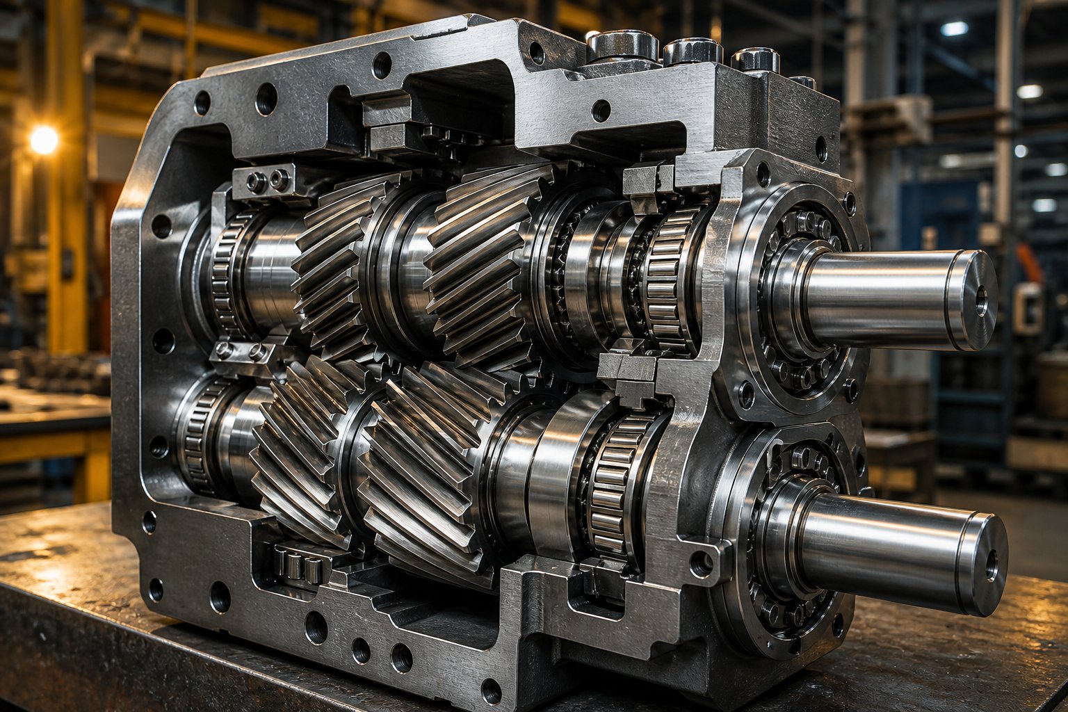
What Is a Twin Screw Extruder Gearbox and Why It Matters
Imagine a single electric motor spinning at high speed on one end, and two parallel screw shafts demanding slow, powerful, perfectly synchronized rotation on the other. Something has to bridge that gap. That something is the twin screw extruder gearbox — and it performs one of the most mechanically demanding jobs in polymer processing.
A twin screw extruder gearbox is a specialized speed-reduction and torque-distribution unit that takes a single motor's rotational output, reduces its speed, multiplies its torque, and splits the driving force equally across two synchronized parallel output shafts connected to the extruder's co-rotating or counter-rotating screws.
Unlike a standard industrial gearbox that drives one output shaft, this unit must deliver precise angular timing between two outputs. Even a fraction of a degree in timing error under load can cause the intermeshing screws to interfere, resulting in immediate mechanical damage. That requirement alone sets a twin screw gearbox apart from virtually every other gear-driven power transmission system in industrial use.
What a Twin Screw Extruder Gearbox Actually Does
At its core, a gearbox for twin screw extruder applications performs three simultaneous tasks. First, it reduces speed. Electric motors typically run at 1,000 to 3,000 RPM, but extruder screws need rotational speeds far lower — often in the range of 200 to 600 RPM for compounding work. The gear train steps down motor speed through one or more reduction stages to reach the target output RPM.
Second, it multiplies torque. Speed reduction through gear ratios directly amplifies the torque available at the output shafts. This is critical because twin screw extrusion involves forcing highly viscous polymer melts and filled compounds through the barrel, a process that demands enormous rotational force. Modern high-performance units deliver torque densities up to 18 Nm/cm3, enabling the processing of demanding materials like glass-filled polyamide.
Third — and this is what makes the twin screw gearbox for extruder systems unique — it splits one input into two outputs while keeping both shafts locked in exact rotational synchronization. The gear mesh arrangement ensures equal torque distribution so neither screw is overloaded or lagging behind its partner. Unequal load sharing would cause inconsistent melt processing, product defects, and accelerated wear on both the screws and the gearbox itself.
Where the Gearbox Fits in the Extrusion Drive Train
You'll find the gearbox sitting at the heart of a straightforward power path. The electric motor generates rotational energy at its output shaft. A coupling — rigid, flexible, or fluid-type — connects the motor shaft to the gearbox input shaft, transmitting rotation while managing minor misalignment and damping vibration.
Inside the gearbox housing, the input shaft drives through one or more gear reduction stages. At the final stage, the gear train divides the power into two parallel output shafts spaced at a precise center distance that matches the extruder's screw geometry. These output shafts connect directly to the twin screws through splined or keyed couplings.
The gearbox also absorbs significant axial thrust loads. As the screws push molten material forward against die back-pressure, the reaction force drives each screw rearward into the gearbox. Specialized thrust bearing arrangements inside the housing handle these forces, which can range from 2.5 kN on small laboratory machines to over 3,400 kN on large production extruders. Without this thrust-absorbing capability, the screws would push themselves out of alignment within minutes of startup.
Every component in this drive train — motor, coupling, gearbox, and screws — must be precisely matched. An undersized gearbox bottlenecks the entire system, regardless of how powerful the motor is. The real engineering challenge lies in how the internal gear architecture achieves all of these functions simultaneously, and that is where the critical design differences begin.
How a Twin Screw Extruder Gearbox Works
Knowing what a twin screw extruder gearbox does is one thing. Understanding how it does it — mechanically, stage by stage — is what separates someone who can read a datasheet from someone who can diagnose a problem, specify a replacement, or optimize a drive system. So let's open the housing and trace every gear mesh from input to output.
The principle starts with a single rotating shaft entering the gearbox from the motor side. That shaft carries a helical pinion gear — the smallest and fastest-spinning gear in the entire assembly. From this single point of entry, the gear train must accomplish three things simultaneously: reduce the rotational speed, multiply the torque, and split the power path into two perfectly synchronized outputs. Each of these tasks is handled by a distinct mechanism inside the gear train, and they all work together in a tightly choreographed sequence.
How Torque Splits from One Input to Two Outputs
Picture the input pinion meshing with a larger driven gear on an intermediate shaft. This first mesh performs the initial speed reduction and torque multiplication — the larger gear turns slower, but with proportionally greater rotational force. So far, this looks identical to any standard industrial gearbox.
The critical difference appears at the torque distribution stage. In a gearbox for a parallel twin screw extruder, the intermediate shaft carries a gear (or set of gears) that meshes simultaneously with gears on two separate output shafts. This is where one power stream becomes two. Each output shaft receives exactly 50% of the available torque.
Why does equal distribution matter so much? Twin screw extruders rely on the precise interaction between two intermeshing screws to convey, melt, mix, and pressurize material. If one screw receives more torque than its partner, the material experiences uneven shear and residence time. The result is inconsistent melt quality, degraded product properties, and uneven mechanical loading that accelerates wear on one side of the machine.
The most common torque-splitting arrangement is the parallel three-axis gear structure, where power transmits from the input shaft through an intermediate shaft to two output shafts arranged in parallel. In this layout, one output shaft (the A-axis) typically has generous dimensional space for larger gears with a high safety factor. The second output shaft (the B-axis), however, is constrained by the center distance between the two screws — which is fixed by the extruder's barrel geometry and cannot be changed. This makes the B-axis the mechanical bottleneck of the entire gearbox.
To overcome this limitation, advanced designs use a double-sided symmetrical drive structure. Instead of driving the B-axis from one direction, two sets of gears engage the B-axis from opposite sides — top and bottom. This approach cuts the load at each gear mesh point in half, effectively doubling the torque capacity without increasing the gear size. Even more importantly, the opposing radial forces cancel each other out, eliminating bending stress on the B-axis entirely. The shaft experiences pure torsion — a couple drive — which dramatically extends bearing life. Twin screw extruder gearboxes and motors paired with this architecture can achieve bearing service lives exceeding 72,000 hours, compared to roughly 20,000 hours for conventional single-sided designs.
Shaft Synchronization and Speed Reduction Explained
Torque splitting alone is not enough. Both output shafts must rotate at exactly the same speed and maintain precise angular timing relative to each other. Even a slight speed mismatch between the two screws would cause the intermeshing flight elements to collide, resulting in catastrophic damage within seconds.
Synchronization is achieved through the gear mesh geometry itself. When a single intermediate gear drives both output gears simultaneously, the tooth engagement enforces identical rotational velocity on both shafts. Every tooth that enters mesh on one output gear has a corresponding tooth entering mesh on the other. This mechanical linkage is inherently self-synchronizing — as long as the gears are manufactured to tight tolerances and properly assembled, the two outputs cannot drift out of phase during operation.
Speed reduction, meanwhile, follows a fundamental relationship that governs all gear-driven systems:
At constant power, halving the output speed doubles the available torque. A twin parallel screw extruder gearbox with a 15:1 total ratio reduces motor speed by a factor of 15 and multiplies torque by approximately 15 times, minus small efficiency losses of 1 to 2 percent per gear stage.
Multi-stage reduction is necessary because achieving the full ratio in a single gear pair would require an impractically large driven gear. Instead, the total ratio is distributed across two or three stages — each stage typically providing a ratio between 3:1 and 8:1. The stages multiply together: a two-stage gearbox with individual ratios of 4:1 and 5:1 delivers a total ratio of 20:1. This cascading approach keeps gear sizes manageable while achieving the high torque multiplication that polymer processing demands.
Power Flow Through the Gear Train
Tracing the complete power path from motor input to screw output helps clarify how each stage builds on the one before it. The table below breaks down the journey of rotational energy through a typical twin screw extruder gearbox:
| Stage | Component | Function | Result |
|---|---|---|---|
| 1 — Power Input | Input shaft with helical pinion | Receives full motor speed and torque via coupling | High-speed, low-torque rotation enters the gearbox |
| 2 — First Reduction | Intermediate shaft with large driven gear and smaller output pinion | First-stage speed reduction and torque multiplication through gear ratio | Speed drops, torque increases proportionally |
| 3 — Second Reduction (if present) | Second intermediate shaft or compound gear set | Additional speed reduction for high-ratio applications | Further torque amplification to meet processing demands |
| 4 — Torque Distribution | Distribution gear meshing with both output shaft gears | Splits torque equally (50/50) to two parallel output shafts | Two synchronized power streams at target speed and torque |
| 5 — Thrust Absorption | Thrust bearing assemblies on each output shaft | Absorbs axial reaction forces generated by screws pushing material forward | Axial loads contained within the gearbox housing, protecting the motor |
| 6 — Power Output | Two parallel output shafts with splined or keyed ends | Transmits synchronized torque to twin screw shafts | Both screws rotate at identical speed with equal torque for uniform processing |
Notice that the thrust absorption stage is not just a passive feature — it is an active load-bearing function that the gearbox performs continuously during operation. The twin screws generate substantial axial forces as they push viscous melt toward the die, and these forces feed directly back into the gearbox. Every output shaft requires its own dedicated thrust bearing arrangement, rated for the specific axial load of the application. This is one of the key differences between a twin screw extruder gearbox and a standard industrial reducer, and it directly influences both the cost and the reliability of the unit.
The elegance of this system lies in how tightly integrated each stage is. The gear tooth profiles, the shaft spacing, the bearing preloads, and the lubrication delivery are all designed as a single interdependent system. Change one variable — say, increase the gear ratio for higher torque — and the bearing loads, heat generation, and oil flow requirements all shift in response. This interdependence is precisely why understanding the internal mechanics matters: it reveals that gearbox architecture is not just a design choice, but a defining constraint on everything the extruder can and cannot do.
Types of Twin Screw Extruder Gearbox Architectures Compared
Gearbox architecture shapes everything downstream — from achievable torque density and thermal behavior to the physical envelope available for installation. Yet most discussions about twin screw extruder gearbox design stop at vague references to "helical gears" without ever explaining that three fundamentally different gear families compete for the same job, each with distinct strengths and limitations. Choosing the wrong one does not just reduce efficiency; it can cap the entire extruder's production potential.
Parallel Shaft Helical vs Planetary vs Bevel-Helical Designs
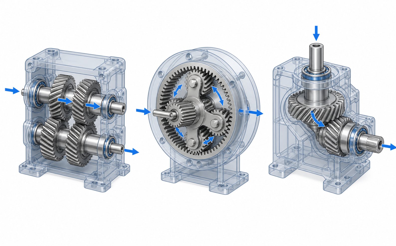
The three primary architectures used in twin screw extruder gearboxes are parallel shaft helical, planetary, and bevel-helical configurations. Each arranges its gears differently, transmits power along a different geometric path, and makes different trade-offs between size, capacity, and cost.
Parallel shaft helical gearboxes are the most widely adopted design family for twin screw extrusion. In this layout, all shafts run parallel to one another inside the housing. Power flows from the input pinion through one or more intermediate helical gear stages, then splits to two parallel output shafts. Because every shaft sits on the same geometric plane, the housing can be compact in height while extending along the axial direction. Helical gear teeth distribute load across multiple contact points simultaneously, which keeps noise low and efficiency high — typically between 96% and 98% for a two-stage unit. The straightforward shaft arrangement also simplifies bearing support and makes maintenance accessible. This is the architecture you'll encounter in the vast majority of compounding and masterbatch production lines.
Planetary gearboxes take an entirely different approach. A central sun gear meshes with multiple planet gears arranged in a ring, all orbiting inside an outer ring gear. This concentric layout packs an enormous amount of gear contact area into a small radial footprint, delivering the highest torque density of any gear architecture — sometimes two to three times greater than a parallel shaft unit of the same external dimensions. Efficiency remains competitive, generally above 95% per stage. The trade-off? Manufacturing complexity is substantially higher. Each planet gear must be machined and assembled to identical tolerances, and the load-sharing between planets requires precision that drives up both production cost and lead time. Planetary designs appear most often in applications where space constraints are severe or where extreme torque density is non-negotiable.
Bevel-helical gearboxes combine a bevel gear input stage with subsequent helical reduction stages. The bevel stage redirects the power flow by 90 degrees, which means the motor can be mounted perpendicular to the extruder axis rather than in-line with it. This right-angle arrangement is valuable in plant layouts where axial space is limited — imagine a production floor where the motor simply cannot extend straight back from the extruder barrel. After the bevel stage changes direction, standard helical stages handle the speed reduction and torque splitting. Efficiency takes a modest hit at the bevel stage (roughly 1% to 3% more loss than a purely helical mesh), and the bevel gears themselves generate more heat under heavy loads. However, the layout flexibility often outweighs this penalty in space-constrained installations.
| Architecture | Layout Description | Torque Density | Efficiency (per stage) | Compactness | Typical Applications | Relative Cost |
|---|---|---|---|---|---|---|
| Parallel Shaft Helical | All shafts parallel; power flows axially through helical gear stages to dual outputs | Moderate to High | ~97–99% | Moderate — elongated axially | Compounding, masterbatch, reactive extrusion, general-purpose twin screw lines | Low to Moderate |
| Planetary | Sun gear drives multiple planet gears inside a ring gear; concentric, multi-contact layout | Very High (2–3x helical) | ~95–97% | Excellent — small radial footprint | High-torque, space-constrained applications; large-diameter extruders | High |
| Bevel-Helical | Bevel stage redirects power 90°, followed by helical reduction stages to dual outputs | Moderate | ~94–97% | Good — allows perpendicular motor mounting | Retrofit installations, space-limited plant layouts, conical twin screw extruder gearbox applications | Moderate to High |
One important note: the bevel-helical configuration is particularly common in conical twin screw extruder gearbox designs. Conical extruders use tapered screws that converge toward the die end, and the wider feed-end shaft spacing combined with the narrower output geometry lends itself naturally to a right-angle input arrangement. If you're working with PVC pipe or profile extrusion equipment, there's a strong chance the gearbox under the cover is a bevel-helical unit.
Co-Rotating vs Counter-Rotating Gearbox Configurations
Beyond the gear architecture itself, the rotation direction of the two output shafts introduces another layer of mechanical complexity. A co-rotating twin screw extruder gearbox drives both output shafts in the same rotational direction. A counter-rotating unit drives them in opposite directions. This distinction sounds simple, but it cascades into profoundly different internal designs.
In a co-rotating configuration, both output gears are driven from the same side of the distribution gear. The gear mesh forces on both outputs act in the same circumferential direction, and the axial thrust loads generated by the helical gear teeth point the same way on each shaft. Bearing arrangements can be essentially mirrored, and the symmetry of the loading simplifies both design and maintenance. Co-rotating twin screw extruders adopt a fully intermeshing screw geometry that produces a self-wiping action — material is forcibly handed off between screw flights at the intermeshing zone, suppressing stagnation and keeping the residence time distribution narrow. This self-wiping behavior makes the co-rotating configuration the dominant choice for compounding, polymer alloying, reactive extrusion, and nanocomposite processing.
Counter-rotating configurations demand a more complex gearbox layout. When the two output shafts spin in opposite directions, the axial thrust forces act in opposing directions — one shaft pushes forward while the other pushes backward. The thrust bearing arrangements must be engineered to handle these opposing loads independently, often requiring heavier-duty bearing assemblies and a more robust housing structure. The gear mesh that reverses one shaft's direction also introduces an additional engagement point, which can slightly reduce overall transmission efficiency.
Why choose counter-rotation despite the added complexity? Counter-rotating twin screw extruders generate lower shear stress between the screws compared to co-rotating machines. Material is drawn into the intermeshing region and compressed through a calendering effect — repeated compressive and elongational deformation under relatively gentle conditions. This characteristic is ideal for thermally sensitive materials like rigid PVC, where high shear would trigger decomposition. Counter-rotating machines allow extrusion at lower temperatures while maintaining stable material transport, making them the standard for PVC pipe, sheet, and profile extrusion.
How to Match Gearbox Architecture to Your Application
Selecting the right twin screw extruder gearbox design comes down to three practical questions:
- What material are you processing? High-viscosity compounds, engineering plastics with fillers, and reactive extrusion processes demand high torque density — pointing toward parallel shaft helical or planetary architectures paired with co-rotating outputs. Thermally sensitive materials like rigid PVC steer you toward counter-rotating configurations, often in bevel-helical housings.
- What are your space constraints? If the plant layout allows a straight-through motor-to-extruder arrangement, parallel shaft helical offers the best combination of performance and cost. Tight floor plans or retrofit situations may require a bevel-helical unit to mount the motor at 90 degrees. Extreme space limitations with high torque demands favor planetary designs.
- What is your budget and lead time tolerance? Parallel shaft helical gearboxes are the most economical to manufacture and the easiest to source as standard catalog items. Planetary units cost significantly more and may require longer lead times for custom configurations. Bevel-helical designs fall in between, with cost driven largely by the precision required in the bevel stage.
Keep in mind that the gearbox architecture also constrains future upgrades. A parallel shaft helical gearbox designed for a specific center distance and torque rating cannot simply be swapped for a planetary unit without re-engineering the mounting interface, coupling arrangement, and possibly the barrel alignment. Choosing the right architecture at the outset avoids costly retrofits down the road.
Architecture determines what the gearbox can deliver. But within any architecture, the actual performance envelope is defined by a set of technical parameters — torque rating, power capacity, gear ratio, axial thrust capacity, and thermal limits — that govern how hard you can push the unit in daily operation.
Key Technical Parameters That Define Twin Screw Extruder Gearbox Performance
A gearbox datasheet can look deceptively simple — a grid of numbers, units, and abbreviations that seems straightforward until you realize that misreading a single parameter can lead to chronic overloading, premature bearing failure, or a machine that never reaches its rated throughput. The challenge is not finding twin screw extruder gearbox specifications. The challenge is knowing which numbers actually matter for your application and how they interact with each other.
Seven core parameters define the performance envelope of every twin screw extruder gearbox. Each one answers a different engineering question, and together they form a complete picture of what the unit can — and cannot — do under real production conditions. The table below presents all seven in a scannable format before we explore the critical ones in detail.
| Parameter | Unit | Definition | Why It Matters |
|---|---|---|---|
| Torque Rating | Nm (Newton-metres) | Maximum continuous torque each output shaft can transmit under normal operating conditions | Directly determines whether the gearbox can handle the rotational resistance created by viscous polymer melt and filled compounds without gear tooth fatigue |
| Power Capacity | kW (kilowatts) | Total input power the gearbox can accept from the motor continuously | Sets the ceiling on motor size; exceeding this rating generates more heat and mechanical stress than the housing, bearings, and lubrication system can manage |
| Gear Ratio | Dimensionless (e.g., 15:1) | The factor by which motor input speed is reduced at the output shafts | Governs the trade-off between output speed and torque multiplication — higher ratios deliver more torque but lower screw RPM |
| Output Speed Range | RPM | The range of rotational speeds available at the output shafts | Must align with the screw speed requirements of the target application; too fast risks material degradation, too slow limits throughput |
| Center Distance | mm (millimetres) | Fixed spacing between the centerlines of the two parallel output shafts | Must exactly match the screw geometry of the extruder barrel — even a fraction of a millimeter off prevents proper screw installation |
| Axial Thrust Load Capacity | kN (kilonewtons) | Maximum continuous axial force the thrust bearings on each output shaft can absorb | Twin screws generate substantial rearward forces as they push melt toward the die; insufficient thrust capacity causes bearing fatigue before the gears ever show wear |
| Thermal Rating | kW (kilowatts) | Maximum power the gearbox can dissipate as heat without oil temperature exceeding safe limits | When ambient temperatures are high or cooling is inadequate, the thermal rating — not the mechanical rating — becomes the actual operating limit |
Sounds like a lot to track? It is. But here's the practical reality: most gearbox problems trace back to just two or three of these parameters being overlooked during specification. Let's break down the ones that cause the most trouble.
Torque Rating and Power Capacity
Torque rating is the single most consequential number on any twin screw extruder gearbox specification sheet. It tells you how much rotational force each output shaft can deliver continuously without exceeding the fatigue design limits of the gear teeth and bearings. Every other parameter ultimately serves or constrains this one.
The relationship between torque and power is governed by a straightforward formula: Torque (Nm) = Power (kW) x 9,550 / Speed (RPM). This means that for a given motor power, reducing the output speed through a higher gear ratio automatically increases the available torque. A 75 kW motor driving through a 25:1 gearbox at 97% efficiency delivers roughly 11,980 Nm at the output — enough to process standard polyolefins on a mid-size machine, but potentially marginal for high-viscosity materials like rigid PVC or heavily filled compounds.
Here's where many engineers get tripped up: confusing peak torque with continuous rated torque. Some datasheets prominently display a peak overload rating — often 150% to 250% of the continuous figure — because it looks more impressive. But peak torque applies only to brief transient events lasting seconds, not to sustained production. Sizing a gearbox based on its peak rating rather than its continuous capacity means the unit runs at or near 100% of its actual mechanical limit during normal operation. The result? Cumulative gear tooth fatigue that leads to pitting, spalling, and eventual fracture — typically on a two-to-three-year failure cycle.
Torque demand scales dramatically with screw diameter. The relationship follows an approximate cube law: doubling the screw diameter roughly octuples the required torque. A 60 mm screw processing HDPE may demand 3,000 to 7,000 Nm, while a 150 mm screw processing the same material can require 40,000 to 100,000 Nm. For twin screw extruder gearbox specifications, always start from screw diameter and material viscosity, then work backward to determine the minimum continuous torque rating.
Power capacity, meanwhile, sets the upper limit on how large a motor you can connect to the gearbox. It accounts not just for mechanical stress on the gears, but for the total heat load the lubrication and cooling systems can manage. Exceeding the rated input power — even if the torque at the output shafts remains within specification — pushes the thermal and bearing systems beyond their design envelope.
A reliable operating guideline backed by field experience: run at 80% of maximum continuous torque and 80% of maximum speed. This margin absorbs process variations, cold-start peaks, and material batch inconsistencies without pushing the gearbox into its fatigue zone.
Gear Ratio and Output Speed Range
Gear ratio is the multiplier that converts motor speed into screw speed — and simultaneously converts modest motor torque into the high output torque that extrusion demands. A gearbox with a 30:1 ratio takes a motor spinning at 1,450 RPM and delivers approximately 48 RPM at the output shafts, while multiplying the available torque by roughly 30 times (minus efficiency losses of about 1 to 2% per stage).
Choosing the right ratio is not arbitrary. It flows directly from two fixed points: the motor's rated speed and the target screw speed for your process. Divide the motor RPM by the desired screw RPM, and you have your required ratio. Two-stage gearboxes typically cover ratios from 6:1 to 25:1, while three-stage units extend the range to 20:1 through 100:1 for low-speed, high-torque applications like rigid PVC profile extrusion.
Output speed range varies significantly by application type. Co-rotating twin screw extruders used for compounding often operate at 200 to 1,200 RPM — high speeds that maximize dispersive mixing energy. Counter-rotating machines for PVC extrusion run far slower, typically 5 to 40 RPM, where the emphasis shifts to gentle material transport under extreme pressure. The gearbox ratio must be matched to the intended speed window, because operating consistently outside the designed range compromises both gear mesh efficiency and bearing life.
There's an important nuance that trips up procurement teams: gear ratio and torque rating are not independently adjustable. Increasing the gear ratio to get more torque means adding gear stages or using larger wheel gears, both of which increase the housing size, weight, and cost. A three-stage gearbox with 97% efficiency per stage delivers only about 91% overall efficiency — the remaining 9% becomes heat that the lubrication system must dissipate. Every ratio increase carries a thermal penalty that must be accounted for in the cooling system design.
Center Distance, Axial Thrust, and Thermal Rating
Center distance is the one parameter with zero tolerance for error. It defines the exact spacing between the two output shaft centerlines, and it must match the extruder barrel's screw bore spacing precisely. Unlike torque or speed — where you have some design margin to work with — center distance is a hard geometric constraint. If the gearbox outputs are 0.5 mm too wide or too narrow, the screws physically cannot be installed, or they'll mesh incorrectly and destroy themselves within hours.
This dimension is typically non-standard. Unlike single-screw gearboxes that use catalog center distances, twin screw units are often built to match specific extruder OEM specifications. When sourcing a replacement or aftermarket gearbox, verifying center distance against the original equipment drawing is the first step — not torque, not ratio, not price.
Axial thrust load capacity is arguably the most underappreciated parameter on any twin screw extruder gearbox PDF or datasheet. As both screws push viscous melt forward against die back-pressure, equal and opposite reaction forces drive each screw rearward into the gearbox. These thrust forces can be enormous — ranging from 2.5 kN for small laboratory machines to 3,400 kN for large production extruders. Every output shaft requires a dedicated thrust bearing assembly, typically using spherical roller thrust bearings or paired tapered roller bearings, engineered specifically for continuous-duty extrusion loads.
Here's the critical insight: thrust bearing fatigue often limits gearbox life before the gear teeth show any significant wear. An undersized thrust bearing fails through progressive fatigue even when the gear train handles the torque without issue. Bearing calculated life (L10h) for continuous extrusion duty should target a minimum of 20,000 to 50,000 operating hours — and that target assumes the bearing operates at its design load, not above it. Specifying tight gear accuracy class (DIN quality class 5 or better) improves how evenly thrust loads distribute across the bearing surfaces, directly extending bearing service life.
Thermal rating rounds out the specification picture by answering a question most engineers forget to ask: can the gearbox reject enough heat to stay within safe operating temperatures? Gear mesh friction and bearing loads generate heat at every stage. Although helical gearboxes run at 95% to 98% efficiency, the power losses in a large unit can still amount to several kilowatts of waste heat. If the lubrication system cannot dissipate this energy fast enough, oil temperature climbs above the recommended limit — typically 80 degrees Celsius for mineral oil or approximately 100 degrees Celsius for synthetic PAO formulations.
The consequences of sustained overheating cascade quickly. Every 10 degree Celsius rise above the design temperature roughly halves the remaining oil life. Thinner oil at elevated temperatures fails to maintain adequate film thickness at gear meshes and bearings, accelerating metal-to-metal contact and wear. Shaft seals degrade faster in the heat, leading to leaks and contamination ingress. In high-ambient-temperature environments or on machines running near maximum power capacity, the thermal rating — not the mechanical torque rating — becomes the true performance ceiling. Monitoring oil sump temperature at the start of every shift is one of the simplest and most effective maintenance practices available.
These seven parameters do not exist in isolation. They form an interconnected web: increasing torque demands a larger gear train, which increases heat generation, which stresses the thermal rating, which may require a more capable cooling system that increases cost and physical size. Understanding these relationships transforms a datasheet from a list of numbers into a map of the gearbox's real capabilities — and its hidden limits. Those limits become especially visible when the gearbox faces the specific demands of different industrial applications.
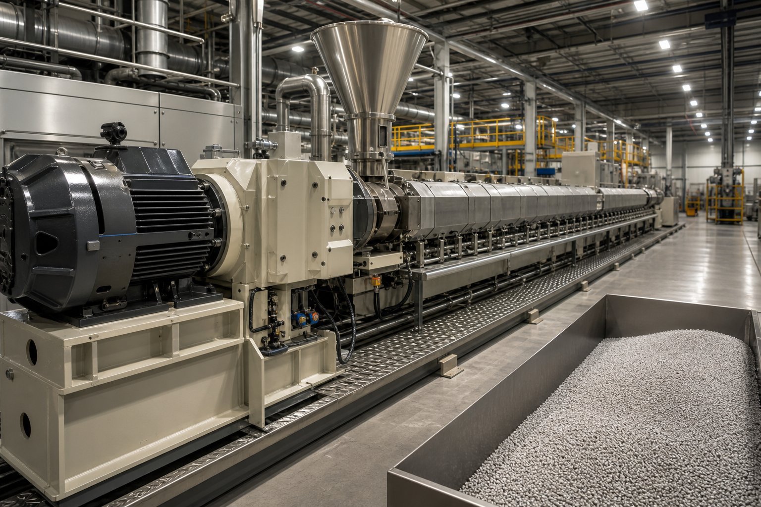
Industry Applications That Depend on Twin Screw Extruder Gearboxes
Every parameter on a gearbox datasheet exists because a real-world application pushed the engineering limits hard enough to demand it. Torque ratings, thermal ceilings, and axial thrust capacities are not abstract numbers — they represent the specific mechanical punishment that different processing environments inflict on the drive system every hour of every shift. Understanding how each twin screw extruder gearbox application stresses the unit differently is what separates a well-specified machine from one that fails ahead of schedule.
Here is a quick summary of the major application areas and the primary gearbox demand each one creates:
- Polymer compounding — sustained high torque for dispersive and distributive mixing of fillers, reinforcements, and additives into viscous polymer melts
- Masterbatch production — precise, stable speed control to maintain consistent pigment concentration and additive distribution across long production runs
- Reactive extrusion — variable torque tolerance as in-barrel chemical reactions continuously change melt viscosity in real time
- Devolatilization — high-speed operation to maximize screw surface renewal rates for efficient volatile and moisture removal
- Lithium battery electrode mixing — extreme torque density combined with resistance to highly abrasive electrode slurry materials under near-cleanroom conditions
Compounding and Masterbatch Production
Polymer compounding is the application most people picture when they think of a twin screw plastic extruder gearbox. The process involves blending base polymers with additives — glass fibers, mineral fillers, flame retardants, impact modifiers, UV stabilizers — to create engineered compounds with specific performance properties. The gearbox faces relentless high-torque demand because dispersing solid additives into a viscous polymer matrix requires enormous shear energy delivered continuously over hours or days of production.
Consider a compounding line processing 40% glass-fiber-reinforced polyamide. The abrasive filler dramatically increases melt viscosity and screw resistance compared to neat polymer. A twin screw extruder gearbox for compounding this material must deliver sustained torque at or near the upper end of its rating — often 80% of maximum continuous capacity — without thermal runaway or bearing fatigue. Screw speeds for compounding typically range from 200 to 600 RPM, and some high-intensity formulations push beyond 1,000 RPM, meaning the gearbox must handle both high torque and high speed simultaneously.
Masterbatch production places a slightly different emphasis on the gearbox. Here, the goal is consistency rather than brute force. Color masterbatch requires extraordinarily uniform pigment dispersion — visible streaks or specks in the final product mean the entire batch is rejected. The gearbox must maintain rock-steady output speed with minimal fluctuation, because even small speed variations translate into inconsistent shear history and uneven pigment distribution. While torque demands are generally moderate compared to heavily filled engineering compounds, speed stability and low vibration become the critical gearbox performance factors.
Reactive Extrusion and Devolatilization
Reactive extrusion turns the extruder into a continuous chemical reactor. Processes like polymer grafting, chain extension, and controlled degradation take place inside the barrel while material moves through the screw channels. What makes this uniquely challenging for the gearbox is the dynamic torque profile. As chemical reactions progress along the barrel length, melt viscosity can spike or drop unpredictably — grafting maleic anhydride onto polypropylene, for example, initially increases viscosity before the reaction moderates it. The gearbox experiences rapid torque fluctuations that standard fatigue calculations based on steady-state loads do not fully capture. Gear tooth contact stresses cycle more aggressively, and bearing loads shift faster than in conventional compounding.
Devolatilization flips the priority from torque to speed. When the goal is removing residual solvents, moisture, or unreacted monomers from a polymer melt, the extruder relies on maximizing surface area renewal — exposing fresh melt surface to vacuum ports as rapidly as possible. This demands high screw speeds, often at the top end of the gearbox's rated output range. Although the torque requirement per shaft may be moderate (because devolatilization typically works with relatively low-viscosity melts), the gearbox must sustain elevated RPM continuously without excessive heat buildup from gear mesh friction and bearing windage losses.
Emerging Applications in Battery and Advanced Materials
Perhaps the most demanding new frontier for twin screw extruder gearbox technology is lithium battery electrode manufacturing. As Thermo Fisher Scientific highlights, twin screw extruders play a crucial role in mixing active electrode materials — lithium compounds, conductive carbon additives, and binders — into the homogeneous slurries or dry electrode films that become the heart of lithium-ion battery cells.
This application pushes gearbox specifications in directions that traditional polymer processing never required. Electrode slurries are intensely abrasive. Active materials like lithium iron phosphate and graphite particles wear aggressively against metal surfaces, and any metallic contamination from the equipment risks short-circuiting the finished battery cell. The gearbox must deliver high torque density to process these stiff, paste-like mixtures while maintaining absolute cleanliness — no oil leaks, no seal degradation, no particulate shedding from worn components.
Beyond batteries, advanced materials like carbon nanotube masterbatches, biodegradable polymer blends, and ceramic-filled composites are all pushing twin screw extruder gearbox requirements toward higher torque per unit volume. These emerging applications are a primary driver behind the industry's migration toward planetary and advanced parallel shaft architectures capable of delivering more mechanical energy in a smaller physical package.
What unites every one of these applications — from commodity compounding to cutting-edge electrode mixing — is a shared vulnerability: the gearbox is only as reliable as its weakest internal component under sustained load. And sustained load, inevitably, leads to wear. Understanding where and how that wear develops is what separates proactive maintenance from unplanned downtime.
Common Failure Modes and How to Prevent Them
A twin screw extruder gearbox does not fail all at once. It fails in slow motion — weeks, months, sometimes a full year of escalating symptoms that are entirely detectable if you know what to look for. The gear teeth develop microscopic surface cracks long before a tooth fractures. Bearings broadcast their distress through subtle vibration signatures long before a raceway shatters. Oil darkens, heats up, and fills with metal particles long before the lubrication system starves a critical contact point.
The frustrating truth? The direct cost of a replacement gearbox accounts for only 15% to 25% of the total cost when an unplanned failure hits a running production line. The remaining 75% to 85% is indirect — lost production, emergency procurement premiums, overtime labor, wasted raw material in the barrel, and downstream equipment sitting idle. A gearbox that costs a few hundred thousand to replace can easily generate total losses five to ten times that figure when the failure is unplanned. Every failure mode described below is preventable. Here is how each one develops and exactly what to do about it.
Gear Tooth Fatigue and Bearing Failures
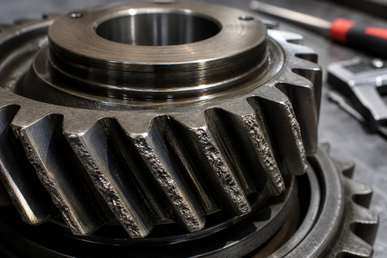
Gear tooth fatigue is the most common long-term wear mechanism inside any twin screw extruder gearbox. Every time two gear teeth come into mesh, an intense contact pressure — known as Hertzian contact stress — concentrates at the tooth surface. In a healthy, well-lubricated gear pair, a thin elastohydrodynamic oil film separates the metal surfaces and distributes the load across a finite contact zone. But even with perfect lubrication, millions of loading cycles produce cumulative subsurface shear stress that eventually initiates tiny fatigue cracks just below the tooth surface.
These cracks grow horizontally beneath the surface and eventually break through, causing small hemispherical pits to form on the tooth flank — a condition called micropitting. You'll notice it first as a grey, frosted appearance on the tooth surfaces. Left unchecked, the pits coalesce and deepen into spalling, where chunks of tooth material detach entirely. Spalling increases backlash, reduces load-carrying area, and concentrates stress on the remaining tooth surface — accelerating the damage exponentially until full tooth fracture occurs.
What pushes the timeline from decades to just a few years? Operating near the gearbox's torque limit is the biggest accelerator. When the machine regularly runs at 90% to 100% of its rated continuous torque — common in heavily filled polymer compounding — the cyclic bending stress at the tooth root approaches the material's fatigue limit. Cold-start shock loads compound the problem: starting a loaded extruder without a controlled ramp-up subjects the gear teeth to transient stresses two to three times higher than steady-state values. Each shock load drives the fatigue crack a little deeper. Eventually, the crack propagates through 70% to 90% of the tooth cross-section, and the final fracture is sudden and catastrophic — sending tooth fragments through the housing and into adjacent gear meshes.
Bearing failure under axial load is the second most frequent cause of twin screw extruder gearbox repair. Unlike standard industrial gearboxes that deal primarily with radial loads, twin screw units must absorb enormous axial thrust forces. As the screws push viscous melt forward against die back-pressure, the reaction force drives each screw rearward into the gearbox thrust bearings — continuously, for every second of operation. These forces can reach thousands of kilonewtons on production-scale equipment.
Conventional radial bearings simply cannot handle this type of loading. Twin screw gearboxes use specialized thrust bearing arrangements — typically spherical roller thrust bearings or paired tapered roller bearings — designed specifically for continuous axial duty. The failure mechanism mirrors gear tooth fatigue: cyclic contact between rolling elements and raceways produces subsurface fatigue cracks that eventually cause raceway spalling. Metal flakes from the damaged raceway contaminate the oil, which then abrades other bearings and gear surfaces — triggering a cascade of secondary failures.
The most dangerous aspect of thrust bearing failure is what happens when it progresses undetected. A failed thrust bearing allows the output shaft to shift axially. In a twin screw extruder, even a fraction of a millimeter of axial movement can cause the screw flights to contact the barrel bore — destroying both the screws and the barrel, components that are typically far more expensive than the bearing itself. This is why thrust bearing failure is considered uniquely catastrophic compared to other gearbox failure modes.
Prevention follows a clear pattern. Size the gearbox with an adequate service factor — a continuous operating load at or below 80% of the rated maximum. Use controlled soft-start procedures to eliminate cold-start shock loads on gear teeth. Monitor axial shaft play on each output shaft with a dial indicator every six months to catch thrust bearing degradation before it reaches the point of screw contact. And replace bearings based on calculated L10h fatigue life targets — typically 20,000 to 50,000 operating hours — rather than waiting for audible symptoms.
Lubrication and Thermal Management Challenges
If gear tooth fatigue and bearing failure are the diseases, lubrication failure is the condition that enables almost every one of them. A twin screw extruder gearbox factory builds each unit around a lubrication system engineered to maintain a continuous oil film at every gear mesh and bearing contact point. When that system fails — through wrong oil selection, contamination, neglected changes, or insufficient cooling — the consequences cascade through every internal component simultaneously.
Oil viscosity selection is the starting point. Too thin, and the oil film cannot support the contact pressures at the gear tooth interface, allowing metal-to-metal contact that triggers scuffing — a rapid, friction-driven destruction mode that can ruin tooth surfaces within minutes of onset. Too thick, and the oil generates excessive churning losses that raise internal temperatures, accelerate oxidation, and paradoxically thin the oil through overheating. Most twin screw gearboxes specify ISO VG 220 or 320 gear oil — mineral EP formulations for standard duty, synthetic PAO for high-temperature or extended-drain applications.
Contamination is the silent killer. In a plastic extrusion environment, fine polymer dust, glass fiber particles, and moisture are constantly present around the gearbox. A degraded shaft seal that allows even microscopic abrasive particles into the oil transforms every lubricated contact point into a grinding zone. Metal particle monitoring through oil analysis is the most powerful single condition monitoring technique available — a 100 ml oil sample sent to a laboratory every three to six months reveals iron content (gear and shaft wear), chromium content (bearing race wear), water contamination, and particle count long before any visual or audible symptoms appear.
Thermal management ties directly into lubrication health. Gear mesh friction and bearing loads generate heat at every stage of the gear train. Although high-quality helical gearboxes run at 95% to 98% efficiency, even a 3% to 5% power loss on a 200 kW input amounts to 6 to 10 kW of waste heat that must be continuously removed. Oil cooling circuits — typically water-cooled heat exchangers or air-cooled radiators — handle this thermal load under normal conditions.
Trouble begins when cooling capacity drops. Scale buildup in water-cooled heat exchangers, dust accumulation on air-cooled fins, or insufficient cooling water flow gradually degrades heat rejection capability. Oil temperature creeps upward. Every 10 degree Celsius rise above the design temperature roughly halves the remaining oil life, thins the oil film, and accelerates seal degradation. If the rising temperature goes unaddressed, a thermal runaway develops: thinner oil generates more friction, which produces more heat, which thins the oil further. This positive feedback loop can cascade from an elevated but manageable temperature to catastrophic component failure in a matter of weeks.
Twin screw extruder gearbox maintenance programs should enforce oil changes at 3,000 to 5,000 operating hours for mineral oil and 8,000 to 12,000 hours for synthetic PAO — with those intervals halved when operating temperatures consistently exceed 75 to 80 degrees Celsius. The oil change is, without exaggeration, the single maintenance action with the greatest impact on gearbox service life. Skipping one to save a few hundred dollars can initiate a failure cascade costing tens of thousands.
Early Warning Signs and Preventive Monitoring
Every failure mode described above broadcasts warning signals long before catastrophic breakdown. The challenge is not that gearboxes fail without warning — it's that the warnings are subtle enough to miss during a busy production shift. Train your maintenance team to watch for these specific indicators:
- Unusual vibration — a new or changing vibration pattern at the gearbox housing. Gear tooth defects produce vibration at the gear mesh frequency and its harmonics; bearing defects create vibration at characteristic bearing defect frequencies. Monthly or quarterly vibration measurements at defined housing positions, trended over time, provide two to six months of advance warning before audible noise appears.
- Rising oil temperature — an upward drift in sump temperature at constant production conditions signals increasing internal friction from developing wear, degraded oil, or reduced cooling capacity. Read and record oil temperature at the start of every shift. A consistent climb of 5 to 10 degrees Celsius above baseline warrants immediate investigation.
- Oil discoloration and metallic debris — dark, cloudy oil or visible metallic particles on the magnetic drain plug confirm active internal wear. Clean and inspect the drain plug magnet monthly. Increased particle density — even fine particles invisible to the naked eye — should trigger an immediate laboratory oil sample.
- Abnormal noise — a new rumbling, grinding, or rhythmic knocking from the gearbox. Rumbling that increases with speed typically indicates bearing damage. Rhythmic knocking at the gear mesh frequency points to tooth surface damage. Either finding justifies stopping the machine at the earliest safe opportunity for inspection.
- Oil seepage at shaft seals — visible moisture or oil film around the output shaft exits. Shaft seal failure has dual consequences: oil leaks out, and abrasive contaminants leak in. A minor seep that seems cosmetic can introduce enough particulate contamination to trigger accelerated gear and bearing wear within 12 to 24 months.
- Rising motor current at constant conditions — if motor amperage trends upward while screw speed, material type, and feed rate remain unchanged, the gearbox is presenting increased mechanical resistance. Modern variable-speed drives log current continuously and can reveal gradual friction increases that other monitoring methods miss.
The most effective preventive monitoring program combines all of these methods into a layered system. Daily temperature and oil level checks catch sudden changes. Monthly magnetic plug inspections and vibration spot-checks catch developing trends. Quarterly or semi-annual laboratory oil analysis and formal vibration analysis provide the precision data needed to schedule repairs before a minor issue becomes a production-stopping emergency.
Imagine a realistic failure cascade: a missed oil change leads to degraded lubrication, which causes micropitting, which generates metallic particles, which contaminate the oil, which abrade bearing raceways, which raise friction and temperature, which degrade seals, which drop oil levels, which starve gear meshes — and within six to eighteen months, the gearbox is destroyed. The initiating event? A single skipped oil change. The total damage? Potentially fifty to one hundred times the cost of the oil and labor that would have prevented it.
Building this kind of monitoring discipline takes effort, but the payoff is extraordinary. And it becomes even more powerful when you understand how the gearbox interacts with every other component in the extrusion drive system — because a problem that looks like a gearbox failure often originates in the motor, the coupling, or the screw design.
The Complete Extrusion Drive System and How Each Component Interacts
A gearbox problem that looks like a gear tooth failure may actually originate upstream in a mismatched motor. A vibration pattern blamed on the gearbox may trace back to a worn coupling. A bearing that fails "prematurely" may have been perfectly sized for the original screws but critically undersized for the replacement screw profile installed six months ago. The twin screw extruder drive system gearbox does not operate in isolation — it sits at the intersection of four interdependent components, and a mismatch in any one of them cascades through the entire chain.
Understanding these interactions transforms how you diagnose problems, specify replacements, and evaluate twin screw extruder gearbox prices. A unit that looks expensive on a purchase order may actually be the cheapest option when you account for the motor, coupling, and screw compatibility it enables — or the premature failures it prevents.
Matching Motor Specifications to Gearbox Input Requirements
Twin screw extruder gearbox and motor selection is not a matter of pairing the biggest available motor with the highest-rated gearbox. It is a matter of alignment across three variables: power, speed, and torque characteristics.
The motor's rated power must not exceed the gearbox's rated input power capacity. This sounds obvious, but it is routinely violated when plant engineers upgrade a motor for higher throughput without verifying that the gearbox can absorb the additional heat and mechanical stress. A 250 kW motor bolted onto a gearbox rated for 200 kW input will not immediately break anything — but it pushes the lubrication system, bearings, and gear teeth beyond their thermal and fatigue design envelopes, shortening service life significantly.
Motor speed determines the required gear ratio. A four-pole AC motor running at approximately 1,450 RPM paired with a gearbox ratio of 15:1 delivers roughly 97 RPM at the output shafts. Change to a six-pole motor running at 960 RPM with the same gearbox, and output speed drops to 64 RPM — which may be too slow for your compounding process but ideal for PVC profile extrusion. As Plastics Technology emphasizes, the motor and gearbox combination should target approximately 70% of maximum motor current and 70% of maximum screw speed during normal operation, leaving headroom for future rate increases and more viscous resins.
Torque characteristics matter too. Variable-frequency drives (VFDs) alter the motor's torque-speed curve, and some VFD configurations deliver constant torque below base speed but reduced torque above it. If the gearbox ratio is chosen assuming full motor torque at all speeds, operating above base speed with a VFD can starve the screws of the torque they need — causing the motor to run at maximum current while the extruder underperforms.
Coupling Selection and Vibration Management
The coupling between motor and gearbox is easy to overlook — it is a relatively small, inexpensive component compared to everything on either side of it. But it serves a critical dual function: transmitting full motor torque to the gearbox input shaft while compensating for minor shaft misalignment and damping torsional vibration.
Three coupling types appear in twin screw extrusion drive systems:
- Rigid couplings — transmit torque with zero backlash and maximum efficiency, but demand near-perfect shaft alignment. Any angular or offset misalignment transmits directly into the gearbox input bearings, accelerating wear. Suitable only for precision-aligned installations with minimal thermal expansion.
- Flexible couplings — use elastomeric elements, disc packs, or gear teeth to accommodate small angular and offset misalignments. These are the most common choice for extrusion lines. However, as IVC Technologies cautions, a flexible coupling does not neutralize the damaging effects of misalignment — it merely prevents the coupling itself from failing. The bearings on both sides still experience damaging cyclical forces from misaligned shafts, even with a flexible element installed.
- Fluid couplings — use hydraulic fluid to transmit torque, providing a soft-start capability that eliminates the shock loads discussed in the failure modes section. Particularly valuable on large extruders where cold-start torque spikes pose the greatest risk to gear teeth. The trade-off is a 2% to 4% efficiency loss through fluid slip during normal operation.
Regardless of coupling type, laser alignment to standard industry tolerances should be performed at installation and rechecked annually or whenever the motor or gearbox is repositioned. Alignment shifts caused by thermal expansion, foundation settling, or pipe strain are among the most common — and most preventable — sources of gearbox input bearing failure.
Aligning Gearbox Output with Screw Design Parameters
On the output side, the gearbox must match the twin screws across three critical dimensions: center distance, torque demand, and speed requirement. The interaction is tighter than most operators realize — every screw design decision echoes back into the gearbox specification.
Screw diameter fixes the center distance. A 65 mm co-rotating twin screw extruder has a specific shaft center spacing dictated by its barrel geometry, and the gearbox outputs must match this dimension exactly. Screw profile — the arrangement of conveying, kneading, and mixing elements along the shaft — determines how much torque resistance the process generates. An aggressive kneading block configuration for dispersive mixing of nano-fillers creates dramatically higher torque demand than a gentle conveying-dominated profile processing the same polymer at the same throughput. Throughput targets, meanwhile, set the required screw speed, which flows backward through the gear ratio to determine the motor speed.
The danger lies in changing one element without re-evaluating the others. Upgrading to a more aggressive screw profile to improve mixing quality increases torque demand. If the gearbox was originally specified with a modest service factor, the "upgraded" screw may push the unit past its continuous torque rating — triggering exactly the gear tooth fatigue described in the previous chapter. Similarly, increasing throughput by raising screw speed means the motor must deliver more power, which means more heat entering the gearbox, which stresses the thermal rating.
The table below maps these interactions explicitly, showing how each component's parameters influence every other component in the drive system:
| Parameter | Motor Impact | Coupling Impact | Gearbox Impact | Screw Impact |
|---|---|---|---|---|
| Motor Power (kW) | — | Must transmit full rated torque without slip or overheating | Must not exceed rated input power; excess power becomes unmanageable heat | Determines maximum available energy for melting, mixing, and pressurizing |
| Motor Speed (RPM) | — | Higher speed increases alignment sensitivity | Determines required gear ratio for target output speed | Output speed must fall within optimal processing window for the material |
| Coupling Type | Affects vibration transmitted to motor bearings | — | Rigid coupling demands tighter alignment; fluid coupling reduces start-up shock loads | Torsional damping from flexible couplings smooths torque delivery to screws |
| Gear Ratio | Constrains motor speed selection for target screw RPM | Higher ratios increase input shaft torque, requiring higher coupling rating | — | Fixes the available output speed and torque multiplication |
| Center Distance (mm) | No direct effect | No direct effect | Must match exactly; non-negotiable geometric constraint | Fixed by screw and barrel geometry; cannot be adjusted |
| Screw Profile / Torque Demand | Aggressive profiles raise motor current; may require larger motor | Higher torque loads increase coupling fatigue risk | Must not exceed continuous torque rating; dictates required service factor | — |
| Throughput Target (kg/hr) | Higher throughput demands more power at higher speed | Increased torque and speed raise coupling thermal and mechanical loads | Higher speed increases gear mesh heat; higher torque stresses teeth and bearings | Higher feed rates increase barrel pressure and axial thrust force |
The core lesson this matrix reveals is that no single component in the drive system can be oversized or undersized without consequence. An oversized motor paired with an adequately rated gearbox does not add safety margin — it creates the potential for the motor to deliver loads the gearbox was never designed to withstand. An undersized coupling between a perfectly matched motor and gearbox becomes the weakest link that fails first. And a screw redesign that ignores the gearbox's torque ceiling turns a process improvement into a reliability disaster.
Successful drive system optimization means sizing every component as part of a system, not as individual purchases. That perspective becomes especially important when you move from engineering specification to the practical realities of sourcing — where the choices between OEM replacements, aftermarket alternatives, and custom-engineered solutions each carry different implications for how well the complete drive system performs.
How to Select and Source the Right Twin Screw Extruder Gearbox
Specifying a gearbox on paper is one thing. Actually buying the right one — at the right price, from the right supplier, delivered in time to avoid production losses — is an entirely different challenge. The procurement process for a twin screw extruder gearbox sits at the intersection of mechanical engineering, supply chain management, and hard budget reality. Get it right, and you secure years of reliable operation. Get it wrong, and you inherit someone else's problem.
Whether you're commissioning a new extrusion line, rebuilding a worn unit, or sourcing an emergency replacement after an unplanned failure, the decision tree follows the same basic structure. You need to define what you need technically, decide which sourcing path fits your situation, evaluate suppliers against criteria that actually matter, and execute procurement in a disciplined sequence that prevents costly oversights.
OEM vs Aftermarket vs Custom-Engineered Gearbox Options
Three distinct sourcing paths exist, and each carries a different balance of risk, cost, and lead time. Choosing between them depends heavily on your specific situation — a planned upgrade allows different options than a gearbox that failed last Tuesday.
OEM replacement gearboxes come directly from the original extruder manufacturer. You get a unit engineered to the exact specifications of your machine, with matched center distance, torque rating, mounting interface, and coupling dimensions. Compatibility is essentially guaranteed. The downside? Cost and lead time. OEM gearboxes typically carry a premium of 30% to 60% above comparable aftermarket units, and delivery windows can stretch to 12 to 20 weeks depending on the manufacturer and model. For production-critical machines where downtime costs dwarf the price difference, the OEM path offers the lowest technical risk.
Aftermarket alternatives are built by independent twin screw extruder gearbox manufacturers who reverse-engineer or design compatible units to fit existing extruder platforms. Quality spans a wide range — from precision-engineered replacements that meet or exceed OEM specifications, down to budget units with questionable metallurgy and tolerance control. The price advantage is substantial, often 25% to 50% below OEM pricing, and lead times can be shorter because aftermarket suppliers typically maintain broader inventory of standard components. The risk? Dimensional accuracy, material quality, and gear accuracy class must be independently verified. An aftermarket gearbox that is 0.3 mm off on center distance or one DIN quality class below specification will create problems that no price savings can offset.
Custom-engineered solutions make sense when the application has evolved beyond the original machine design. Perhaps you've upgraded to a more aggressive screw profile that demands higher torque than the original gearbox specification. Maybe you're converting a compounding line to process battery electrode slurries and need enhanced sealing and contamination control. Or your plant layout has changed, requiring a different mounting configuration. Custom gearboxes are designed from scratch — or significantly modified from a standard platform — to meet specifications that no catalog unit addresses. Expect longer engineering lead times (often 16 to 24 weeks) and costs 10% to 40% above equivalent OEM units, but you gain a solution precisely tailored to your current and projected operating requirements.
Pros of OEM Replacement
- Guaranteed dimensional and performance compatibility
- Full manufacturer warranty and technical documentation
- Minimal engineering validation required at installation
Cons of OEM Replacement
- Highest purchase cost among the three options
- Longest lead times, especially for older or discontinued models
- Locked into the original specification — no opportunity to improve performance
Pros of Aftermarket
- Significant cost savings with competitive quality from reputable suppliers
- Shorter delivery for standard configurations
- Multiple supplier options create negotiating leverage
Cons of Aftermarket
- Quality varies widely — rigorous supplier vetting essential
- Center distance, gear accuracy, and material grade must be independently verified
- Warranty terms may be less comprehensive than OEM
Evaluating Gearbox Manufacturers and Suppliers
Regardless of which sourcing path you choose, the supplier evaluation criteria remain consistent. The difference between a vendor who ships you a reliable gearbox and one who ships you a future failure comes down to a handful of verifiable factors.
Engineering support is the first filter. A serious twin screw extruder gearbox manufacturer or supplier should be able to review your application requirements — screw diameter, center distance, torque demand, speed range, axial thrust loads — and confirm or recommend specifications. If a supplier simply asks for a model number and quotes a price without discussing application details, that is a red flag. The gearbox is too critical and too application-specific for a commodity purchasing approach.
Customization capability separates the best suppliers from the rest. Can they work from your drawings or samples to produce a unit that matches your exact requirements? This matters enormously for replacement scenarios where the original OEM is no longer available, the model has been discontinued, or the original design needs modification. China-based twin screw extruder gearbox suppliers have become increasingly competitive in this area, offering the ability to manufacture from customer-provided drawings, reverse-engineer from physical samples, and deliver units at pricing significantly below European or North American OEMs. Companies like NANHAIYA, for example, support sourcing of extrusion spare parts — including screw components, die heads, and custom parts manufactured from drawings or samples — which can be valuable when a gearbox replacement also requires matching screw elements or ancillary components from a single supply chain.
Quality certifications provide a baseline assurance floor. Look for ISO 9001 quality management systems at minimum. For gear manufacturing specifically, ask about gear accuracy class testing (DIN or AGMA standards), material certifications for alloy steel components, and heat treatment records for case-hardened gears. Reputable twin screw extruder gearbox manufacturers in India and China increasingly hold these certifications and can provide full material traceability documentation on request.
Regional sourcing considerations have shifted dramatically over the past decade. A China twin screw extruder gearbox supplier that might have been dismissed a decade ago for quality concerns now competes head-to-head with European manufacturers on precision, material quality, and surface finish — often at 40% to 60% lower cost. The key is due diligence. Request sample inspection reports, gear tooth profile measurement data, and references from existing customers in similar applications. Twin screw extruder gearbox manufacturers in India have similarly expanded their capabilities, particularly for conical twin screw extruder gearbox configurations used in PVC processing, where the domestic market drives high production volumes and competitive pricing.
Availability of related extrusion components is a practical advantage that many procurement teams undervalue. When a gearbox fails or wears out, the screws, barrels, heater bands, thermocouples, and other wear components often need attention at the same time. A supplier who can source or manufacture the gearbox alongside replacement screw elements, die heads, and pelletizing blades reduces the number of vendors to manage and simplifies logistics — particularly during a rebuild that involves multiple component replacements.
Building a Sourcing Checklist for Your Next Gearbox Project
Procurement mistakes on twin screw extruder gearboxes almost always trace back to skipping a step in the evaluation sequence. The following checklist puts the steps in logical order, ensuring that technical requirements are locked before commercial negotiations begin — not discovered after a non-returnable purchase order has been issued.
- Document the application requirements completely. Record the material being processed, throughput target, screw diameter, screw profile type, barrel length, operating temperature range, and any special environmental conditions (cleanroom-adjacent, corrosive atmosphere, high ambient temperature).
- Capture all critical gearbox dimensions from the existing equipment. Measure or obtain drawings for center distance, output shaft diameter, shaft length, spline or key dimensions, mounting bolt pattern, and overall housing envelope. For a replacement, these dimensions are non-negotiable constraints.
- Define the performance specifications. Specify minimum continuous torque rating per output shaft, total input power capacity, required gear ratio, output speed range, axial thrust load capacity, and thermal rating. Use the 80% rule: the gearbox should run at no more than 80% of its continuous ratings during normal production.
- Determine the sourcing path. Evaluate whether OEM, aftermarket, or custom-engineered is the right fit based on urgency, budget, and whether the original specification still matches current process requirements.
- Identify and pre-qualify at least three potential suppliers. Request engineering capability summaries, quality certifications, reference customer lists, and sample inspection reports. For China twin screw extruder gearbox suppliers or twin screw extruder gearbox manufacturers in India, request recent export references to verify cross-border quality consistency.
- Request detailed technical proposals, not just price quotes. Each proposal should include a complete specification sheet confirming torque, power, ratio, center distance, bearing type and calculated L10h life, gear accuracy class, oil type and volume, cooling system requirements, and overall dimensions with tolerances.
- Verify critical specifications independently. Compare proposed center distance, output shaft geometry, and mounting interface against your documented equipment dimensions. Confirm that gear accuracy class, material grade, and heat treatment meet or exceed the original specification.
- Negotiate commercial terms with total cost in mind. Factor in freight, import duties (for international sourcing), installation support, warranty duration, and spare parts availability. A gearbox that is 15% cheaper but ships without a warranty or technical support may cost far more in the long run.
- Establish inspection and acceptance criteria before placing the order. Define what measurements, tests, and documentation must accompany delivery — dimensional inspection report, gear contact pattern verification, noise and vibration test results, and oil cleanliness certification.
- Plan installation and commissioning support. Confirm whether the supplier provides installation guidance, alignment specifications, break-in procedures, and a commissioning checklist. A properly installed and commissioned gearbox reaches its full rated service life; an improperly installed one begins accumulating damage from day one.
This checklist is not bureaucratic overhead — it is the minimum due diligence that protects a capital investment worth tens of thousands of dollars and a production asset worth far more. Skipping step two (dimensional verification) has caused more costly returns and installation failures than any other single procurement error in the extrusion industry.
The sourcing landscape continues to evolve. Gearbox technology itself is advancing rapidly, with higher torque densities, integrated digital monitoring, and modular architectures reshaping what plant operators can expect from the next generation of drive systems — and influencing how engineers should think about their gearbox strategy going forward.
Future Trends and Practical Next Steps for Your Gearbox Strategy
Gearbox technology does not stand still — and neither do the materials it has to process. The twin screw extruder gearbox that handled standard polyolefin compounding five years ago is increasingly being asked to process high-performance engineering plastics, ceramic-loaded composites, and battery electrode slurries that push torque demands far beyond what previous generations of hardware were designed to deliver. At the same time, digital technologies are transforming how these units are monitored, maintained, and managed across their service lives. If you are specifying, operating, or sourcing drive system components today, these twin screw extruder gearbox technology trends will directly shape your decisions over the next several years.
Higher Torque Density and Advanced Materials
The single most powerful force driving gearbox evolution is the relentless demand for more torque per unit of screw volume. Why? Because the materials entering twin screw extruders keep getting harder to process. Glass-fiber-reinforced polyamides, long-fiber thermoplastic compounds, carbon nanotube masterbatches, and lithium battery electrode pastes all resist screw rotation far more aggressively than conventional polymers. Processing them at commercially viable throughput rates requires enormous mechanical energy concentrated into gearbox housings that cannot grow proportionally larger — the extruder barrel geometry, plant floor space, and mounting interfaces are fixed constraints.
This is where a high torque twin screw extruder gearbox earns its value. Advanced parallel shaft helical designs now achieve torque densities approaching 18 Nm/cm3, and planetary architectures push even higher. Achieving these figures requires simultaneous improvements across multiple fronts: harder, more fatigue-resistant gear tooth materials with optimized case-hardening profiles; precision-ground tooth geometries that maximize the load-bearing contact area at each mesh point; and bearing assemblies engineered for higher axial and radial loads within the same dimensional envelope.
The co-rotating gearbox segment, already the dominant architecture for compounding, is experiencing particularly aggressive growth — market analyses project 8.4% to 8.6% CAGR through 2033, driven largely by demand for precise mixing in high-performance polymer and pharmaceutical applications. Counter-rotating designs are expanding too, especially in North American construction and PVC pipe sectors where the U.S. market alone is projected to reach $750 million by 2033. Both segments share a common trajectory: every new generation of gearbox is expected to deliver more torque in the same footprint as its predecessor.
Digital Monitoring and Predictive Maintenance Integration
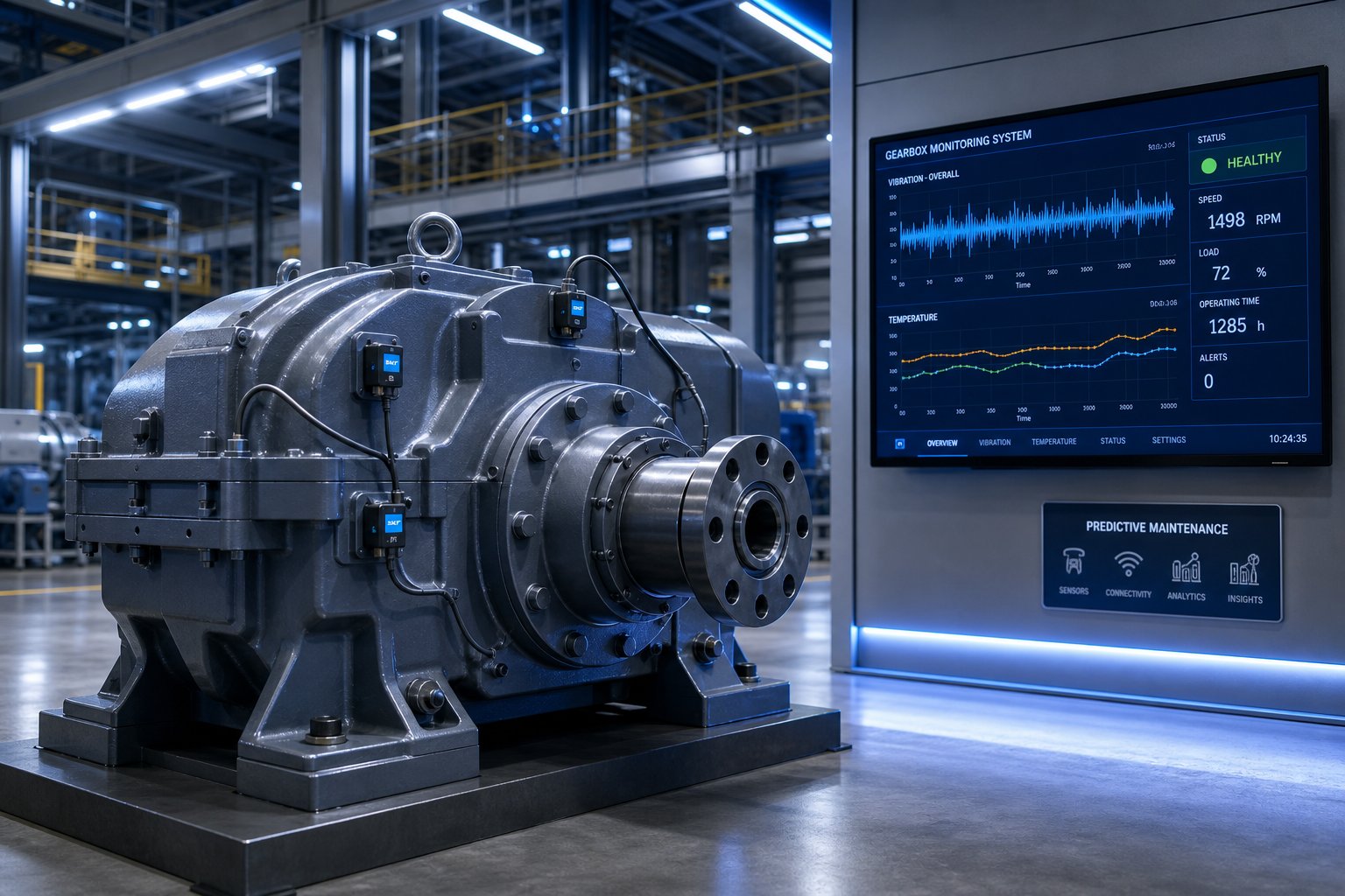
Imagine knowing that a thrust bearing is developing fatigue three months before it reaches a critical stage — without ever opening the gearbox housing. That is the promise of IoT-enabled condition monitoring, and it is rapidly moving from pilot programs to standard practice on production-scale extrusion lines.
Modern smart sensors embedded in or mounted on gearbox housings continuously track the parameters that matter most: vibration signatures at gear mesh and bearing defect frequencies, oil sump temperature trends, lubricant particle counts, and even real-time torque loading through strain-gauge-equipped input shafts. This data streams to centralized maintenance platforms where algorithms compare current readings against baseline values and flag deviations long before a human operator would notice anything unusual.
The shift from preventive to predictive maintenance is not trivial. As Machinefabriek Krimpen details, traditional preventive schedules replace components at fixed intervals regardless of actual condition — sometimes too early (wasting useful life), sometimes too late (after damage has already begun). Predictive systems instead estimate when maintenance should actually be performed based on equipment condition, reducing unplanned downtime while extending the service interval for components that are still healthy.
AI and machine learning models are accelerating this capability. These systems analyze vast datasets of vibration, temperature, and torque readings to identify subtle degradation patterns that human analysts might miss. Over time, they learn the specific operating signature of each individual gearbox — accounting for its unique gear geometry, bearing preloads, and typical process loads — and refine their failure predictions accordingly. The practical result? Maintenance teams can schedule gearbox repairs during planned shutdown windows rather than reacting to catastrophic breakdowns, dramatically reducing the cascade of indirect costs discussed earlier in this article.
Energy efficiency improvements complement the digital monitoring trend. Advanced gear tooth profile optimization — including asymmetric tooth designs that reduce sliding friction and computer-modeled contact patterns that distribute load more evenly — squeezes measurable gains out of each gear stage. Better bearing technology, including hybrid ceramic rolling elements that reduce friction and run cooler, extends both bearing life and thermal headroom. Optimized lubrication systems using synthetic nano-lubricants deliver more consistent film thickness under extreme pressures while resisting thermal degradation longer than conventional mineral oils. Together, these improvements reduce the waste heat that has traditionally been the hidden performance ceiling on high-power gearboxes.
Practical Next Steps for Engineers and Maintenance Teams
The trend toward modular and customized twin screw extruder gearbox configurations rounds out the technology picture. Rather than committing to a single fixed specification for the life of the machine, modular designs allow plant operators to adapt — swapping gear stages to change ratios, upgrading bearing assemblies to handle increased axial thrust from a new screw profile, or adding sensor provisions to an existing housing for digital monitoring. A customized twin screw extruder gearbox built on a modular platform can evolve with your production requirements instead of forcing a full replacement every time the process changes.
So where does all of this leave you practically? Whether you are specifying a new gearbox for a greenfield line, troubleshooting declining performance on an aging unit, or planning a rebuild that needs to last another decade, three actions create the most value:
- Size for tomorrow's materials, not just today's. If your product development roadmap includes higher-filler-content compounds, engineering plastics, or battery-related materials, specify a high torque twin screw extruder gearbox with enough continuous torque margin to handle those future demands. Retrofitting a higher-torque gearbox later costs far more than specifying the right unit upfront.
- Invest in condition monitoring infrastructure now. Even basic monitoring — monthly vibration spot-checks, quarterly oil analysis, daily temperature logging — provides enormous predictive power when trended over time. If budget allows, integrate IoT-enabled sensors and centralized data platforms to move toward true predictive maintenance.
- Build a reliable sourcing network for the complete drive system. Gearbox replacements rarely happen in isolation. When a gearbox comes apart for rebuild or replacement, the screws, barrels, heater bands, thermocouples, die heads, and pelletizing blades often need attention simultaneously. Working with suppliers who can source multiple extrusion components streamlines procurement and reduces lead time. NANHAIYA's Extruder Spare Parts page, for instance, offers maintenance teams and plant buyers a centralized resource for screw-related components, heater bands, thermocouples, die heads, pelletizing blades, and custom parts manufactured from drawings or samples — the kind of one-stop sourcing capability that keeps twin screw extruder drive systems running at peak performance without juggling a dozen separate vendors.
The twin screw extruder gearbox is not just a steel box full of gears. It is the mechanical heart of the extrusion process — the component that translates raw electrical energy into the precise, synchronized, high-torque rotation that transforms raw polymers into engineered products. Understanding its architecture, parameters, failure modes, system interactions, and sourcing realities at the depth this article has covered gives you something no catalog or sales brochure provides: the ability to make genuinely informed decisions about the most critical and expensive rotating component on your production floor.
Twin Screw Extruder Gearbox FAQs
1. What is the main function of a twin screw extruder gearbox?
A twin screw extruder gearbox takes a single motor's rotational output, reduces its speed, multiplies the torque, and splits driving force equally across two synchronized parallel output shafts. It also absorbs the substantial axial thrust loads generated when the screws push molten material forward against die back-pressure. Without this precisely engineered unit, the motor cannot deliver the low-speed, high-torque, perfectly timed rotation that twin intermeshing screws require for uniform polymer processing.
2. What is the difference between co-rotating and counter-rotating twin screw extruder gearboxes?
Co-rotating gearboxes drive both output shafts in the same direction, producing a self-wiping screw action ideal for compounding, reactive extrusion, and nanocomposite processing. Counter-rotating gearboxes spin the shafts in opposite directions, creating a calendering effect with lower shear stress suited for thermally sensitive materials like rigid PVC. Internally, counter-rotating units require more complex thrust bearing arrangements because axial forces act in opposing directions, making the housing design heavier and slightly less efficient than co-rotating counterparts.
3. How do I choose the right gear ratio for my twin screw extruder?
Start by dividing your motor's rated RPM by the target screw speed for your process. For example, a 1,450 RPM motor paired with a 15:1 ratio delivers roughly 97 RPM at the output. High-speed compounding applications typically need ratios producing 200 to 1,200 RPM screw speed, while PVC profile extrusion may require only 5 to 40 RPM. Keep in mind that higher ratios multiply torque but also add gear stages, increase heat generation, and reduce overall efficiency — so the ratio must balance throughput goals with the gearbox's thermal and mechanical limits.
4. What are the most common failure modes in twin screw extruder gearboxes?
The most frequent failures are gear tooth fatigue (micropitting that progresses to spalling and fracture), thrust bearing fatigue from continuous axial loads, and lubrication-related degradation. Gear tooth problems accelerate when the unit regularly operates above 80% of its rated continuous torque or experiences cold-start shock loads. Thrust bearing failure is especially dangerous because even slight axial shaft movement can cause screw flights to contact the barrel bore. Regular oil analysis, vibration monitoring, and temperature trending provide months of advance warning before these issues become catastrophic.
5. Where can I source replacement parts for my twin screw extruder gearbox and drive system?
Replacement gearboxes can be sourced through OEM channels, aftermarket manufacturers, or custom-engineered solutions. OEM units guarantee compatibility but carry premium pricing and longer lead times. Aftermarket and China-based suppliers often deliver competitive quality at 25% to 50% lower cost, though independent verification of center distance, gear accuracy, and material grade is essential. For related extrusion spare parts — including screw components, heater bands, thermocouples, die heads, and pelletizing blades — suppliers like NANHAIYA (nhyscrews.com) offer custom manufacturing from drawings or samples, simplifying procurement when multiple components need replacement simultaneously.
Written by
Nanhaiya Technical Team
Zhoushan Nanhaiya Plastic Machinery Co., Ltd.
The Nanhaiya technical team supports screw and barrel manufacturing projects through application review, technical communication, custom manufacturing coordination, and production and quality control.
Discuss Your Application
Related Articles
More insights on screw barrel technology and plastics processing.

What Nobody Tells You About Screw Barrel For Plastic Machine Design
Oct 10, 2026
Learn how screw barrel for plastic machine design affects melt quality, throughput, and wear life. Covers geometry, resin matching, troubleshooting, and sourcing.
Read Article
Single Screw Extruder for Sheet: Stop Guessing, Start Specifying
Oct 9, 2026
Learn how to specify a single screw extruder for sheet production. Covers screw geometry, resin-specific processing, troubleshooting, and maintenance best practices.
Read Article
PE Pipe Extruder Machine: What Datasheets Won't Tell You
Oct 9, 2026
Learn how a PE pipe extruder machine works, key specs explained, material grade selection, maintenance tips, and buyer guidance beyond the datasheet.
Read ArticleLooking for something else?
Search by material, symptom or product and jump straight to the relevant page.
These are navigation suggestions based on keyword matching — not a quotation, not a delivery commitment, and not a substitute for engineering review. Final specification is confirmed by our engineers against your drawings and processed material.
Need help with screw barrel selection?
Share your machine model, processed material and application. Our team can help with pricing and technical support.