

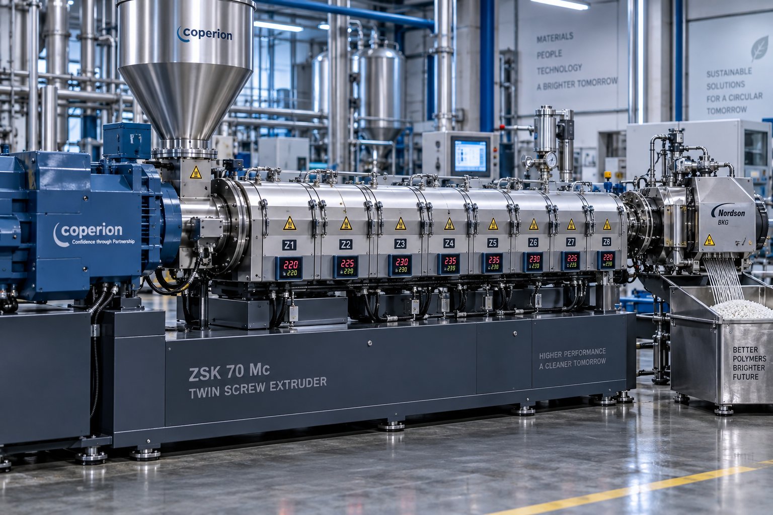
What a Twin Screw Extruder Actually Does in Pelletizing
Imagine feeding a blend of raw polymer resin, mineral fillers, and color pigments into one end of a machine and pulling out thousands of perfectly uniform pellets from the other. That is exactly what a twin screw extruder for pelletizing delivers, and the difference between a line that runs flawlessly and one that generates reject after reject often comes down to how well each stage inside the barrel is understood and controlled.
Defining Twin Screw Extrusion for Pelletizing
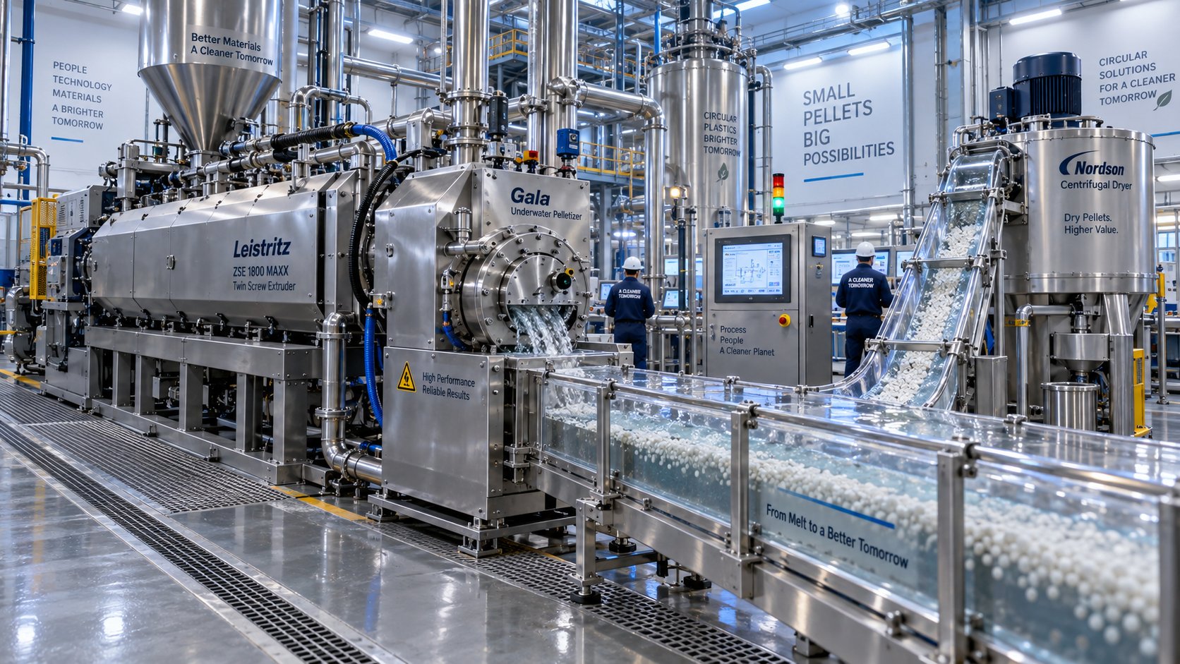
A twin screw extruder for pelletizing uses two intermeshing, co-rotating or counter-rotating screws inside a heated barrel to melt, mix, devolatilize, and pressurize polymer material before pushing it through a die into a pelletizer. The screws are built from modular segmented elements, each designed for a specific task such as conveying, kneading, or pressure generation. Raw feedstock enters the barrel as powder, flake, granule, or a combination of solids and liquids, and the twin screw extrusion process transforms it into a homogeneous melt that is shaped into strands or droplets and cut into pellets of consistent size and composition. Those pellets then serve as the starting material for downstream operations like injection molding, blow molding, or film extrusion.
Why Pelletizing Demands More Than Simple Extrusion
Not every extrusion application places the same demands on the machine. Profile extrusion, for example, prioritizes dimensional stability at the die exit. Film extrusion focuses on uniform gauge and optical clarity. Pelletizing, by contrast, lives or dies on melt homogeneity inside the barrel long before the material ever reaches the die face.
You'll notice that pelletizing requires three conditions working in tight harmony: precise melt temperature control, consistent discharge pressure, and thorough distributive and dispersive mixing. A twin-screw extruder is uniquely suited to deliver all three. Its self-wiping geometry prevents material from stagnating on the screw surfaces or barrel wall, eliminating the dead zones that cause thermal degradation and inconsistency. The modular screw configuration lets engineers place kneading, mixing, and conveying elements exactly where they are needed. And the intermeshing action generates both the high shear forces required to break down filler agglomerates and the gentler redistributive flow needed to spread additives evenly throughout the melt.
These capabilities matter because pellet quality is cumulative. Every second of uneven mixing, every pocket of overheated resin, and every bubble of trapped moisture carries forward into the finished pellet. That reality leads to a principle worth remembering:
Pellet quality is determined not at the pelletizer, but inside the extruder barrel where melt uniformity is established.
A perfectly tuned pelletizer cannot rescue a poorly mixed, thermally inconsistent melt. Conversely, a well-engineered twin screw extrusion process produces a melt so uniform that the pelletizing step becomes almost trivial.
The Full Process Chain at a Glance
Understanding the full sequence of operations inside and around a twin screw extruder helps you pinpoint exactly where problems originate. Each stage hands off to the next, and a weakness in any single link degrades the final pellet. Here is the complete process chain from raw material to finished pellet:
- Feeding - Raw materials are metered into the barrel through gravimetric or volumetric feeders, establishing the recipe ratio and throughput rate.
- Conveying - Screw conveying elements move the solid feedstock forward while controlling fill level and residence time.
- Melting - Kneading blocks and barrel heaters convert the solid material into a molten state through a combination of mechanical shear and conducted heat.
- Mixing - Dispersive and distributive mixing elements ensure fillers are broken down and all components are spatially uniform throughout the melt.
- Venting - Atmospheric or vacuum vent ports remove trapped air, moisture, and volatile compounds from the melt stream.
- Pressurizing - High-pitch conveying elements build the discharge pressure needed to push the melt through the die.
- Die extrusion - The pressurized melt passes through a die plate, forming strands, sheets, or droplets depending on the pelletizing method.
- Pelletizing - A strand cutter, underwater pelletizer, or water-ring pelletizer cuts the extrudate into uniform pellets that are cooled and collected.
Each of these stages involves specific engineering choices, from screw element geometry to barrel metallurgy, and the wrong decision at any point cascades downstream. The difference between co-rotating and counter-rotating screw configurations, for instance, fundamentally changes mixing intensity and throughput behavior, making it one of the first decisions any engineer or buyer must confront.
Co-Rotating vs Counter-Rotating Twin Screw Extruders Compared
That choice between co-rotating and counter-rotating screws is not a minor specification detail. It shapes everything downstream: mixing intensity, maximum throughput, the range of materials you can pelletize, and even the types of defects you are most likely to encounter. Yet many equipment guides gloss over the distinction or treat it as a footnote. For engineers evaluating twin screw extruders for pelletizing, this is one of the most consequential decisions on the entire spec sheet.
Co-Rotating Intermeshing Twin Screw Extruders
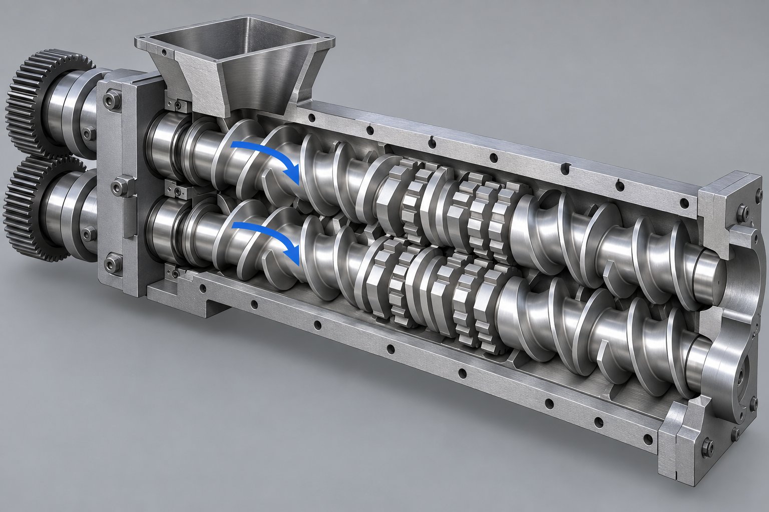
In a co-rotating design, both screws turn in the same direction inside a fully intermeshing geometry. Material is forcibly handed from one screw flight to the next at the intermeshing zone, following a figure-eight path along the barrel length. This geometry produces a self-wiping action that continuously cleans each screw surface, preventing stagnation and keeping the residence time distribution narrow.
Why does that matter for pelletizing? Because narrow residence time distribution means every particle of polymer spends roughly the same amount of time under heat and shear. The result is a melt with consistent thermal history, which translates directly into pellet-to-pellet uniformity in color, mechanical properties, and filler dispersion.
Co-rotating twin-screw extruders also run at significantly higher screw speeds, often exceeding 1,200 RPM on modern machines. High speed combined with intense shear fields between the screws and between screw tips and the barrel wall delivers both dispersive mixing (breaking apart filler agglomerates) and distributive mixing (spreading components evenly). This dual capability makes co-rotating designs the dominant choice for color masterbatch production, mineral-filled compound pelletizing, polymer alloy blending, and reactive extrusion where controlled energy input is critical.
Counter-Rotating Intermeshing and Non-Intermeshing Designs
Counter-rotating intermeshing twin screw extruders flip the script. The screws turn in opposite directions, drawing material into the intermeshing region and compressing it forward. A calendering effect develops at the nip point between the screws, where compressive and elongational deformation disperses material under relatively gentle conditions. Shear heating stays low, and extrusion temperatures can be kept well below what co-rotating machines typically produce.
This behavior makes counter-rotating intermeshing machines ideal for thermally sensitive materials. Rigid PVC, for instance, has a narrow window between processing temperature and decomposition temperature. A co-rotating double screw extruder running at high speed would risk degrading the compound before it ever reached the die. Counter-rotating designs handle PVC dry-blend pelletizing and profile extrusion reliably by operating at high fill levels and low rotational speeds, sometimes below 50 RPM.
Counter-rotating intermeshing machines also feature closed "C-shaped" chambers between the screw flights that function as positive displacement pumps. This pumping action builds stable die pressure without requiring a separate gear pump, an advantage when consistent strand formation is essential for pellet uniformity.
Non-intermeshing counter-rotating designs occupy a different niche entirely. The two screws sit side by side without overlapping, which eliminates the self-wiping effect and reduces dispersive mixing intensity. These machines suit applications where gentle handling matters more than aggressive compounding, such as devolatilization of heat-sensitive polymers or processing low-bulk-density feedstocks. Their geometric freedom allows longer L/D ratios (100:1 or more), enabling extended residence times for processes like multi-stage volatile removal. However, the lack of intermeshing interaction limits their effectiveness for the intensive mixing that most pelletizing applications demand.
Which Configuration Suits Which Pelletizing Application
Choosing the right configuration starts with understanding how each design handles the core requirements of pelletizing. The following table breaks down the three commercially available twin screw extruder types across the criteria that matter most for pellet quality and process efficiency:
| Criteria | Co-Rotating Intermeshing | Counter-Rotating Intermeshing | Counter-Rotating Non-Intermeshing |
|---|---|---|---|
| Mixing Intensity | High (dispersive + distributive) | Moderate (calendering/elongational) | Low to moderate |
| Self-Wiping Capability | Excellent, continuous screw-to-screw wiping | Partial, limited by opposite rotation geometry | None |
| Maximum Screw Speed | 1,200+ RPM | ~600 RPM (high-speed); <50 RPM (low-speed PVC) | Up to ~500 RPM |
| Residence Time Distribution | Narrow, well-controlled via starve feeding | Very narrow due to positive displacement conveying | Broader, harder to control precisely |
| Pumping Efficiency | Moderate (semi-drag flow; may need gear pump for high back-pressure) | High (closed C-chambers act as positive displacement pump) | Moderate (similar to single screw behavior) |
| Typical Pelletizing Applications | Color masterbatch, filled compounds, polymer alloys, reactive extrusion, recycled plastics | Rigid PVC pelletizing, thermally sensitive compounds, pharmaceutical extrusion | High-level devolatilization, niche low-shear compounding, specialty polymers |
A few practical takeaways stand out. If your pelletizing line handles multiple polymer families, frequent recipe changes, or heavily filled formulations, a co-rotating intermeshing machine gives you the broadest operating window. If your primary material is PVC or another heat-sensitive compound where low shear is non-negotiable, counter-rotating intermeshing is the proven choice. Non-intermeshing designs rarely serve as the primary extruder on a pelletizing line, but they fill important roles when extended devolatilization or ultra-gentle conveying is the priority.
Configuration alone, however, does not tell the full story. Even after selecting co-rotating or counter-rotating operation, the question of whether a twin screw or single screw extruder is the right tool for a given pelletizing job still deserves a direct comparison, particularly for processors weighing capital cost against mixing performance.
Twin Screw vs Single Screw Extruders for Pelletizing
Capital cost conversations have a way of simplifying equipment decisions into price tags. A single screw extruder costs less upfront, so why not start there? The answer depends entirely on what you are asking the machine to do. For pelletizing, the gap between these two architectures is not just about dollars. It is about what happens to the material inside the barrel and how that shapes every pellet coming off the line.
Mixing Efficiency and Melt Homogeneity
Here is where the two designs diverge most sharply. A twin extruder delivers two distinct types of mixing simultaneously: dispersive mixing, which breaks apart filler agglomerates, pigment clusters, and gel particles under high shear stress, and distributive mixing, which spreads those broken-down components evenly throughout the melt matrix. The intermeshing screw geometry forces material through narrow gaps between the screw flights and the barrel wall, generating intense, repeatable shear fields that no single screw configuration can replicate on its own.
Single screw extruders, by contrast, rely primarily on the shear gradient in the metering zone to homogenize the melt. The mixing action is largely passive, driven by drag flow between the rotating screw flight and the stationary barrel. For well-compounded pellet feedstock that only needs remelting, this is often sufficient. But when the extruder itself must blend raw resin with fillers, pigments, or additives, the limited mixing capability of a single screw often forces processors to add static mixers or secondary compounding steps just to approach the homogeneity that a twin screw delivers natively.
For pelletizing compounded materials, this difference is not academic. Inconsistent filler dispersion shows up as pellet-to-pellet variation in mechanical properties. Poor color distribution creates visible streaking in downstream molded or extruded parts. And unmelted particles or gels become embedded defects that trigger customer rejections. When the pelletizing line is responsible for producing the compound, not just reshaping it, the mixing gap between single and twin screw extruders becomes the single biggest quality variable.
Feed Flexibility and Self-Wiping Advantages
Imagine your production schedule requires running calcium-carbonate-filled polypropylene in the morning, switching to a glass-fiber-reinforced nylon after lunch, and finishing the day with a color masterbatch based on polyethylene. Each recipe involves different feedstock forms: pellets, powder, chopped fiber, and liquid additives. A twin screw extruder handles this reality through multiple feed ports spaced along the barrel. Main feed hoppers accept polymer pellets or powder. Side feeders introduce glass fibers or mineral fillers downstream, after the polymer is already molten, preventing fiber breakage and ensuring proper wetting. Liquid injection ports deliver plasticizers, coupling agents, or peroxide crosslinkers directly into the melt at precisely controlled rates.
Single screw extruders are far more limited in this regard. They work best with a single feed port at the throat, accepting pre-compounded pellets or uniform granules. Powder feeding is possible but often problematic because the flood-fed conveying mechanism depends on consistent bulk density to maintain stable output. Side feeding and liquid injection, while technically achievable, are rarely practical on single screw platforms because the conveying and mixing zones are not independently configurable.
The self-wiping action of intermeshing twin screw extruders adds another practical advantage that operators appreciate daily. Because the flight of one screw continuously sweeps the surface of the adjacent screw, material cannot stagnate in dead zones. This means faster, cleaner material changeovers. Switching from a dark-colored compound to a light one on a twin screw machine typically takes a fraction of the purge material and time compared to a single screw design, where residual material hides in stagnant corners of the metering zone and must be flushed out gradually. Less scrap during transitions translates directly into higher effective throughput over a full production week.
When a Single Screw Extruder Still Makes Sense
Dismissing single screw extruders entirely would be a mistake. For straightforward re-pelletizing of clean, pre-compounded material where the screw extrusion step only needs to remelt, convey, and pressurize, a single screw machine delivers exactly what is needed at lower capital and operating cost. Think of a converter buying pre-colored, pre-stabilized polyethylene pellets and simply re-pelletizing edge trim or startup scrap. The material is already homogeneous. No additional mixing is required. A single screw extruder handles this job reliably, efficiently, and with less mechanical complexity to maintain.
Single screw systems also tend to be simpler to operate, requiring less specialized training for floor personnel. Their lower screw speeds and fewer wear components mean reduced spare parts inventory and maintenance costs. For processors running a narrow range of clean, consistent materials, these savings compound significantly over the life of the equipment.
The following table puts the key differences side by side across the criteria that matter most when evaluating screw extruders for a pelletizing application:
| Criteria | Twin Screw Extruder | Single Screw Extruder |
|---|---|---|
| Mixing Quality | High: simultaneous dispersive and distributive mixing | Low to moderate: drag-flow shear in metering zone only |
| Feed Flexibility | Accepts pellets, powder, flake, fiber, and liquids via multiple feed ports | Best with uniform pellets or granules through a single feed throat |
| Throughput Range | Wide: adjustable via independent screw speed and feed rate control | Narrower: throughput closely tied to screw speed |
| Residence Time Control | Precise: starve-fed operation allows independent adjustment | Limited: flood-fed operation couples fill level to screw speed |
| Changeover Speed | Fast: self-wiping action minimizes residual material | Slower: stagnant zones require extended purging |
| Capital Cost | Higher: complex gearbox, modular screws, multiple barrels | Lower: simpler mechanical design and fewer components |
| Ideal Pelletizing Scenarios | Compounding and pelletizing filled, blended, or reactive materials; masterbatch; recycled plastics with variable quality | Re-pelletizing clean, pre-compounded scrap or single-polymer regrind |
The pattern is clear: the more your pelletizing process demands from the extruder in terms of mixing, multi-component feeding, and recipe flexibility, the stronger the case for a twin screw platform. The simpler and more consistent your feedstock, the more a single screw machine earns its place on the floor.
Whichever architecture you choose, though, the quality of the pellets ultimately traces back to one place: the screw elements themselves. Their geometry, sequencing, and interaction with the melt define whether you achieve the mixing intensity your formulation requires or fall short in ways that only become visible after pellets reach your customer's hopper.
Screw Element Design Principles for Pelletizing Applications
Screw elements are where theory meets reality in any extruder twin screw setup. You can specify the right machine architecture, select the correct L/D ratio, and invest in premium barrel metallurgy, but if the screw profile is poorly configured, none of those decisions will save your pellet quality. Every element mounted on the splined shaft plays a defined role, and the sequence in which those elements appear along the barrel determines whether your melt arrives at the die uniform and properly tempered or overheated, under-mixed, and full of defects.
This section breaks down the three primary element families, walks through a representative screw profile for a compounding twin screw extruder pelletizing line, and explains the trade-offs that separate a well-engineered configuration from one that generates chronic quality problems.
Conveying, Kneading, and Mixing Element Functions
Think of the modular screw as a toolkit. Each element type solves a different processing problem, and understanding what each one does to the material is the foundation for building a profile that works.
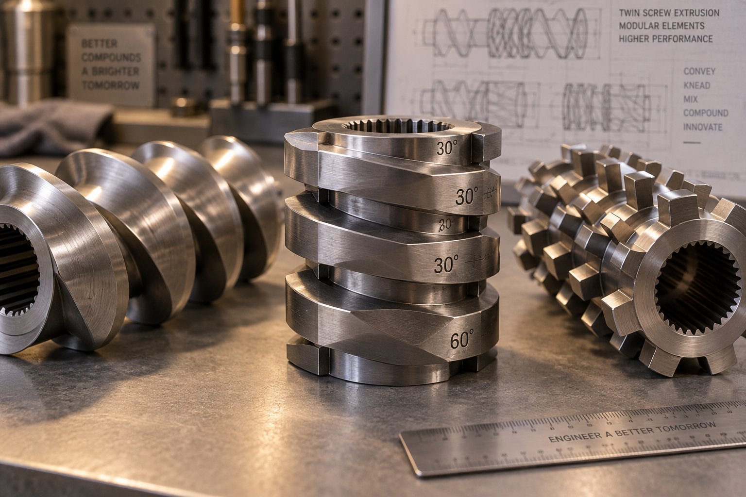
Conveying elements are helical flights that grip and push material forward along the barrel. Their primary job is transport, not mixing. A conveying element with a large pitch moves material quickly with minimal compression, making it ideal for the feed zone where you want to pull raw material into the barrel without generating back-pressure. A shorter pitch compresses and slows the material, building pressure in the metering zone before the die. By varying pitch along the screw, engineers control fill level in each barrel section, which in turn influences how much shear and heat the material experiences at every point. As NC State Extension research notes, conveying ability decreases with decreasing pitch, so selecting the right flight geometry at each position is critical for stable operation.
Conveying elements also play a supporting role around vent ports. Placing large-pitch elements near a degassing zone reduces fill level and pressure, creating the low-fill conditions needed for moisture and volatile gases to escape without melt erupting through the vent opening.
Kneading blocks are the primary mixing workhorses. Each block consists of multiple lobed discs stacked on the shaft, with each disc offset from its neighbor by a defined stagger angle. Three geometric variables govern kneading block behavior:
- Disc width: Narrow discs create more frequent changes in cross-sectional flow, generating higher local pressure fluctuations and stronger dispersive mixing. Wide discs produce smoother flow with less intense shear, favoring distributive action.
- Number of discs (block length): Longer blocks provide more repeated splitting and recombining of the melt, increasing total energy input and broadening residence time. Shorter blocks deliver localized, targeted effects without spiking torque or melt temperature.
- Stagger angle: This is the angular offset between adjacent discs and is the single most powerful lever for tuning mixing intensity. A low stagger angle maintains net forward conveying while delivering moderate shear. A high stagger angle reduces forward pumping, increases back-mixing, and ramps up shear and pressure gradients dramatically.
Beyond geometry, kneading blocks come in three conveying orientations. Forward kneading blocks push material downstream while mixing, making them the safest choice when you need homogeneity without excessive pressure buildup. Neutral kneading blocks have zero net conveying capacity, forcing material to oscillate across the disc faces and dramatically increasing residence time and energy input. Reverse kneading blocks actively push material backward against the overall flow direction, creating intense pressure upstream and generating the highest shear stresses of any kneading geometry. Reverse blocks are powerful tools for dispersive mixing and for creating melt seals that isolate vent zones, but they raise torque and melt temperature significantly, so they must be used with care.
Specialized mixing elements fill the gap between conveying and kneading. Toothed mixing elements (TME), gear-type mixers, and interrupted-flight distributive elements repeatedly split and recombine the melt stream without imposing the high shear stress of aggressive kneading blocks. These elements excel at final-stage homogenization, where the goal is even spatial distribution of already-dispersed additives rather than further particle size reduction. As screw element nomenclature data from NC State Extension illustrates, toothed mixing elements provide distributive mixing with essentially zero dispersive shear effect, making them invaluable for heat-sensitive formulations or fiber-reinforced compounds where preserving filler morphology matters.
Sequencing Elements for Optimal Pellet Quality
Knowing what each element does in isolation is only half the challenge. The real engineering skill lies in sequencing them into a screw profile where each zone hands off to the next in a logical, controlled progression. A twin screw compounding extruder set up for pelletizing typically follows a pattern like this:
- Feed zone (large-pitch conveying elements): Coarse-pitch flights grab incoming pellets, powder, or flake and move them rapidly downstream, keeping the feed throat clear and preventing bridging.
- First kneading block section (melting zone): Forward kneading blocks with moderate stagger angles apply enough shear to initiate melting. The goal here is gradual, controlled melting rather than brute-force plasticization. Research from Leistritz demonstrated that an extended melting zone using narrow-disc kneading blocks produced both lower melt temperatures and higher attainable throughput rates compared to an aggressive melting zone packed with wide-disc neutral and reverse elements.
- Relaxation conveying zone: Standard conveying elements follow the first kneading section, allowing the partially molten material to stabilize thermally before entering the next intensive zone. This relaxation step prevents cumulative overheating.
- Second kneading section (dispersive mixing zone): Higher-stagger kneading blocks, sometimes including a short reverse element, target agglomerate breakup and fine dispersion of fillers and pigments. Because the polymer is fully molten at this point, viscosity is high enough to transmit shear stress directly into particle clusters.
- Distributive mixing zone: Toothed mixing elements or low-stagger kneading blocks spread the now-dispersed components evenly throughout the melt matrix, ensuring pellet-to-pellet consistency in composition.
- Vent and degassing zone (low-fill conveying elements): Large-pitch conveying elements drop the fill level and pressure, creating an open surface for moisture and volatiles to escape through atmospheric or vacuum vent ports.
- Pressure-building conveying zone: Progressively tighter-pitch elements compress the melt and build stable die pressure for consistent strand formation or underwater pellet cutting.
Notice how reverse elements and restrictive kneading blocks serve a dual purpose in this layout. Beyond their mixing function, they create sealing zones, regions of high fill and elevated pressure that prevent gas from migrating backward through the barrel instead of exiting through the vent. Without these melt seals, degassing becomes unreliable. Bubbles end up trapped inside pellets, and surface defects multiply. The seal works because the reverse-pumping action forces material to fully occupy the screw channels, forming a physical barrier that separates the low-pressure vent zone from the higher-pressure upstream mixing sections.
How Element Selection Affects Melt Quality and Pellet Uniformity
Here is the uncomfortable truth about screw design: more mixing is not always better. Every kneading block, every restrictive element, and every reverse-stagger disc converts mechanical energy into heat inside the melt. That energy has nowhere to go except into the polymer itself and, eventually, through the barrel wall via cooling. Push too hard, and the melt temperature climbs well above the target setpoint, regardless of how aggressively the barrel cooling jackets are running.
The consequences of over-aggressive kneading are tangible. Experimental work on a 27 mm co-rotating twin screw extruder showed that an aggressive melting zone design produced melt temperatures 10 to 30 degrees Celsius higher than an extended, gentler configuration processing the same PP resin. At elevated screw speeds, the aggressive design caused visible degradation, including smoke and discoloration, clear indicators that the polymer was being destroyed inside the barrel. Higher melt temperatures also reduced the maximum achievable throughput because the extruder hit its torque limit earlier.
On the opposite end of the spectrum, insufficient kneading creates its own set of failures. Under-mixed melt contains unmelted polymer particles, poorly wetted filler clusters, and uneven additive distribution. These defects carry straight through to the pellet. You'll see them as white specks in colored compounds, as inconsistent melt flow index between pellet batches, or as mechanical property variation that triggers part failures downstream.
Screw design for pelletizing, then, is always a balancing act. The profile must deliver enough dispersive energy to break apart every agglomerate and enough distributive action to spread every component uniformly, while keeping the total thermo-mechanical energy input below the point where degradation begins. Engineers working with heat-sensitive polymers like PVC or certain bioplastics lean toward longer, milder mixing sections with narrow-disc, forward-stagger kneading blocks. Those processing heavily filled engineering resins can tolerate more aggressive dispersive zones because the higher-viscosity melt absorbs shear stress without excessive temperature rise.
The interaction between screw elements and barrel conditions adds another layer of complexity. Counter-intuitively, raising barrel temperature setpoints in the melting zone can actually lower melt temperature. Higher barrel heat softens the polymer earlier, reducing the mechanical energy needed from the kneading blocks to complete melting. This insight underscores why screw configuration cannot be optimized in isolation. It must be tuned alongside barrel temperature profiles, screw speed, and feed rate to find the operating window where mixing quality, melt temperature, and throughput all converge at acceptable levels.
Getting that convergence right depends heavily on two factors that sit just outside the screw profile itself: the barrel's length-to-diameter ratio, which dictates how much room you have for each processing zone, and the feeding system, which determines whether the material arriving at those carefully sequenced elements is consistent enough to produce the results you designed for.
L/D Ratio Selection, Feeding Systems, and Degassing Explained
A perfectly sequenced screw profile means nothing if it does not have enough barrel length to fit every processing zone, or if the material entering the first flight arrives at inconsistent rates. These two factors, barrel length-to-diameter ratio and feeding system design, are among the most frequently underspecified parameters on twin screw extruder plastic processing lines. Get either one wrong, and the carefully engineered kneading and mixing zones discussed earlier cannot do their jobs. Add a third variable, degassing, and you have the trio of upstream decisions that quietly determine whether pellets leave the line clean and uniform or riddled with voids and composition drift.
What L/D Ratio Means and Why It Matters for Pelletizing
L/D ratio is the barrel's total length divided by its screw diameter. A twin screw plastic extruder with 92 mm screws and a barrel measuring 4,048 mm from feed port to discharge flange has a 44:1 L/D ratio. Simple math, but the implications are anything but simple. Every processing zone, feeding, conveying, melting, mixing, venting, and pressurizing, needs physical space on the barrel. Stretch the barrel longer and you gain room to add more mixing elements, additional vent ports, or extended residence time. Shorten it and you save capital cost and floor space, but you sacrifice functional zones that your formulation may require.
Common pelletizing configurations fall into three broad ranges, and the right choice depends almost entirely on what the extruder must accomplish beyond basic melting:
- Short barrels (32:1 to 36:1): These suit simple re-pelletizing or single-component melting where the polymer is already compounded and just needs to be reshaped. A short barrel provides enough length for melting and pressure buildup without the expense of zones that will never be used. Lab-scale and pilot-scale extruders often use shorter L/D ratios for material screening before committing to production geometry.
- Medium barrels (40:1 to 44:1): This is the workhorse range for standard compounding and pelletizing. A 40:1 to 44:1 L/D ratio provides enough length for complete melting, one or two kneading sections, a distributive mixing zone, and a single vacuum vent port. Most color masterbatch, mineral-filled polyolefin, and general-purpose engineering plastic pelletizing lines operate comfortably in this range.
- Long barrels (48:1 to 52:1): Reactive extrusion, multi-stage venting, and heavily filled systems that demand extended mixing and degassing residence time push into this territory. Processing recycled plastics with high moisture and volatile content, or running chemical grafting reactions that produce water as a byproduct, often requires two or even three separate vent zones, each needing its own sealing section and low-fill conveying region. Only a long barrel provides the real estate for all of these zones without compressing other critical sections.
A practical caution: longer is not automatically better. Over-specifying the L/D ratio increases capital cost, floor space requirements, and total residence time. For heat-sensitive polymers, that extra residence time can cause degradation even at moderate barrel temperatures. A machine with a 52:1 barrel running a straightforward polyethylene re-pelletizing job wastes money on barrel sections that sit partially empty and contribute nothing to pellet quality. The goal is to match barrel length to process complexity, not to buy insurance you do not need.
Gravimetric vs Volumetric Feeding and Side Feeder Integration
Sounds like a minor accessory decision? It is not. The feeder is the first link in the process chain, and every inconsistency it introduces, whether a momentary surge or a brief starvation, propagates through every downstream zone. A twin screw extruder for pelletizing operates in starve-fed mode, meaning the screws are never fully filled. The feeder, not the screw speed, controls throughput. That makes feeder accuracy the single most direct lever on pellet weight uniformity and composition consistency.
Two feeder technologies dominate:
Gravimetric (loss-in-weight) feeders continuously weigh the hopper and measure the rate of weight decrease as material discharges. When the actual feed rate deviates from the setpoint, the controller automatically adjusts motor speed to compensate. This self-correcting behavior means that fluctuations in bulk density, which are inevitable when processing powders, regrind flake, or recycled material with variable particle size, do not translate into feed rate variation. The result is tighter control over the recipe ratio and more uniform pellet composition from the start of a run to the end. Gravimetric feeders also provide monitoring and reporting data that supports quality management systems and makes troubleshooting far easier when pellet defects appear.
Volumetric feeders deliver a fixed volume of material per revolution of their dosing mechanism. They are mechanically simpler, less expensive, and perfectly adequate when the feedstock has a consistent, predictable bulk density, such as uniform virgin pellets. The limitation appears when bulk density fluctuates. A hopper refill that introduces a slightly different particle size distribution, or a switch between two lots of the same material with different granule shapes, will change the mass flow rate without triggering any correction from the feeder. Manual recalibration is required each time, and if operators miss the drift, pellet-to-pellet weight and composition variation increases.
For pelletizing lines running multiple components, the feeding system extends well beyond the main hopper. Side feeders, typically twin-screw devices mounted perpendicular to the main barrel, introduce solid additives downstream after the polymer is already fully molten. This approach is critical for two reasons. First, feeding glass fibers or mineral fillers into the main feed throat subjects them to the full shear history of the melting and initial kneading zones, breaking fibers and grinding filler particles far below their optimal size. Introducing them after the melt is established preserves fiber length and filler morphology. Second, downstream addition ensures the polymer melt is hot enough to wet the filler surface immediately, promoting strong interfacial adhesion that translates into better mechanical properties in the finished pellet.
Liquid injection systems add another dimension of feeding flexibility. Plasticizers, coupling agents, peroxides for reactive extrusion, and liquid colorants can be metered directly into the melt stream through injection ports with precision pumps. Accurate liquid dosing is especially important for reactive processes where peroxide concentration controls the degree of crosslinking or chain scission, and even small variations produce measurable changes in melt flow index from pellet to pellet.
Venting and Degassing Zones for Moisture-Sensitive Materials
Even with a perfectly fed, thoroughly mixed melt, pellet quality can collapse at the final hurdle if trapped moisture and volatiles are not removed before the die. Venting is the process of creating a low-pressure zone inside the barrel where dissolved water, entrapped air, residual monomers, and volatile reaction byproducts can escape from the melt surface and be extracted.
Two venting methods are standard on twin screw pelletizing lines:
Atmospheric venting uses an open port in the barrel where gases escape at ambient pressure. This approach handles moderate volatile loads, removing surface moisture and loosely trapped air. Screw elements beneath the vent are configured with large pitch to reduce fill level, exposing a large free surface area of melt to the barrel opening. A stuffing screw or vent insert prevents melt from creeping upward through the port.
Vacuum venting applies sub-atmospheric pressure, typically 10 to 50 millibar, to the vent port using a vacuum pump system. The reduced pressure dramatically lowers the boiling point of water and other volatiles, pulling them out of the melt far more aggressively than atmospheric venting alone. Vacuum systems can reduce volatile content to below 100 ppm, a level that atmospheric venting cannot consistently achieve with hygroscopic polymers. For demanding applications, multi-stage vacuum configurations use two or three successive vent zones, with the first stage removing the bulk of the volatiles and subsequent stages polishing the melt to ultra-low residual levels.
Why does this matter so much for pelletizing specifically? Because inadequate degassing produces defects that are invisible until the pellets are reprocessed downstream. Internal voids and micro-bubbles form when trapped moisture flashes to steam as the melt exits the die, creating porous pellets that look fine on the surface but perform poorly in injection molding or film extrusion. Surface defects like splay and silver streaks appear on molded parts made from under-degassed pellets. And for polymers susceptible to hydrolysis, residual moisture actively degrades the polymer chains during processing, reducing molecular weight and destroying mechanical properties.
The following materials are especially sensitive and typically require aggressive vacuum degassing during pelletizing:
- Polyester (PET, PBT): Highly hygroscopic; moisture causes hydrolytic chain scission that reduces intrinsic viscosity. A polyester extruder line without vacuum venting risks producing pellets unsuitable for bottle-grade or fiber-grade applications.
- Polyamide (PA6, PA66): Absorbs atmospheric moisture rapidly; residual water causes yellowing, reduced tensile strength, and inconsistent melt viscosity during downstream processing.
- Recycled plastics: Post-consumer and post-industrial regrind contain variable moisture levels, printing ink residues, adhesive remnants, and other volatile contaminants that require multi-stage venting to remove.
- Bio-polymers (PLA, PHA, PBAT): Thermally sensitive and moisture-reactive; even small amounts of residual water trigger molecular weight loss and discoloration at processing temperatures.
Proper degassing depends on the melt seal concept discussed in the screw element chapter. Reverse kneading blocks or restrictive elements placed upstream of the vent port create a fully filled, high-pressure zone that prevents air from being sucked backward into the barrel through the vent opening. Without this seal, the vacuum pump pulls ambient air into the melt stream rather than pulling volatiles out, defeating the entire purpose of the venting zone and potentially oxidizing the polymer in the process.
Getting L/D ratio, feeding precision, and degassing right puts you in a strong position, but the real test comes when pellets start dropping off the line and you need to evaluate what you are actually producing. Defects have a way of revealing exactly which upstream decision was slightly off, and knowing how to read those defects is the fastest path to a stable, high-quality pelletizing operation.
Troubleshooting Common Pellet Defects and Quality Issues
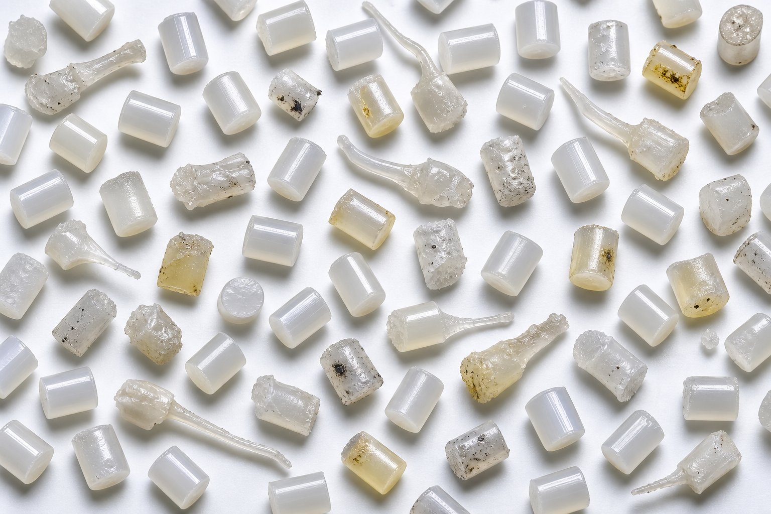
A pellet rolling off the cutter that looks slightly elongated, has a tiny tail hanging off one edge, or feels rougher than usual is telling you something. Every defect is a symptom, and the root cause almost always traces back to a specific point in the process chain you have already built: feed inconsistency, screw configuration mismatch, inadequate degassing, worn components, or a die condition that nobody noticed drifting out of spec. The challenge is decoding which symptom points to which cause, especially when multiple variables shift simultaneously on a busy production floor.
This section gives you a structured diagnostic framework. Whether you are running a used twin screw extruder that has logged thousands of hours or commissioning a brand-new double screw extruder machine, the defects and their solutions follow the same logic.
Identifying Common Pellet Defects and Root Causes
When pellet quality problems appear, operators often reach for the most obvious adjustment: changing cutter speed or tweaking die temperature. Sometimes that works. More often, it masks the real issue until it resurfaces worse than before. The table below maps seven of the most frequently encountered pellet defects to their likely root causes and the corrective actions that address the actual problem rather than just the visible symptom.
| Defect | Likely Root Causes | Corrective Actions |
|---|---|---|
| Tails and streamers | Excessive die swell from melt elasticity imbalance; dull or worn cutter blades; melt temperature too high at the die face; improper blade-to-die-plate gap | Reduce melt temperature by adjusting barrel zones or screw speed; sharpen or replace cutter blades; verify blade-to-die clearance per OEM specification; consider reducing die hole diameter to increase shear rate and reduce swell |
| Excessive fines and dust | Brittle polymer fracture during cutting due to low melt temperature; cutter speed too high relative to strand velocity; excessive water cooling quenching the pellet surface before cut completes | Raise melt temperature to improve strand ductility; synchronize cutter speed with throughput rate; adjust process water temperature in underwater pelletizers; inspect die plate for partially blocked holes forcing uneven strand diameters |
| Uneven pellet size | Inconsistent feed rate causing throughput surges; partially plugged die holes creating unequal strand flow; melt pressure fluctuation from worn screw elements or unstable screw speed control | Switch to gravimetric feeding for tighter rate control; clean or replace die plate; check screw element wear and replace degraded kneading blocks; verify drive motor speed stability and controller tuning |
| Internal voids and bubbles | Inadequate degassing from poor vacuum level or compromised melt seal; residual moisture in hygroscopic feedstock; entrapped air from flooded feed zone or poor vent port design | Verify vacuum pump performance and target 20-50 mbar at vent port; pre-dry moisture-sensitive resins to recommended levels; confirm reverse kneading blocks upstream of vent are creating a proper melt seal; reduce screw speed if vent flooding occurs |
| Discoloration and black specks | Material degradation from excessive shear or prolonged residence time; dead zones in barrel or die where polymer stagnates and chars; contamination from previous material changeover | Reduce kneading intensity or lower screw speed to decrease shear heating; purge barrel thoroughly during changeovers; inspect die adapter and screen changer for stagnant flow pockets; check barrel liner for scoring that traps material |
| Surface roughness or melt fracture | Die lip buildup (die drool) from volatiles or low-molecular-weight fractions condensing at the die exit; melt fracture from excessive wall shear stress at the die hole entry; processing temperature too low for the material viscosity | Clean die face regularly during production; raise die temperature to reduce melt viscosity at the exit; increase die hole land length to stabilize flow; add processing aids or lubricants to reduce wall friction |
| Moisture content out of spec | Insufficient drying of feedstock before the extruder; inadequate venting capacity for the moisture load; vacuum system leaks reducing effective degassing; process water contamination in underwater pelletizing | Extend pre-drying time or increase dryer temperature within safe limits; add a second vacuum vent zone or upgrade vacuum pump capacity; pressure-test vacuum plumbing for leaks; verify pellet dryer performance after water separation |
A critical point emerges from this table: most defects have multiple possible causes. Approaching troubleshooting by changing one variable at a time and allowing the process to stabilize before making additional modifications is the only reliable method. Adjusting three settings simultaneously might fix the visible problem, but you will never know which change actually worked, and the next time conditions shift, you are guessing again.
How Barrel Wear Contributes to Quality Decline
Some quality problems do not appear overnight. They creep in over hundreds or thousands of operating hours, so gradually that operators adapt without realizing the baseline has shifted. Barrel liner and screw element wear is the most common culprit behind this slow-motion quality drift, and it deserves attention precisely because it hides so well.
Here is what happens mechanically. As the barrel liner wears, the clearance between screw flight tips and the barrel wall increases. That growing gap reduces the shear stress the screw can impose on the melt, directly weakening dispersive mixing. Filler agglomerates that were once reliably broken apart now survive the kneading zone intact. Pigment distribution becomes less uniform. Melt homogeneity degrades pellet by pellet, batch by batch, until a customer complaint finally forces an investigation.
Worn screw elements compound the problem. Kneading block disc edges lose their sharp profiles, reducing the high-shear zones that drive particle breakup. Conveying element flights thin out, decreasing pumping efficiency and allowing material to leak backward past the flight tips. This leakage changes residence time distribution, meaning some fraction of the melt sits in the barrel longer than intended, absorbing more heat and inching closer to degradation. Dead zones form where material stagnates against a worn barrel surface, charring slowly until black specks break free and contaminate the melt stream.
Certain materials accelerate this wear cycle dramatically. Fillers like calcium carbonate, glass fiber, and titanium dioxide are far more abrasive than the polymer matrix itself, grinding against metal surfaces continuously during screw rotation. Glass-fiber-reinforced compounds are especially aggressive because long fibers entangle at the feed port and shear into sharp particles that intensify abrasion throughout the barrel. High-wear zones concentrate in four critical areas: the feed section where solid particles first contact the barrel wall, the side feeder entry point where abrasive fillers are introduced, the mid-barrel region where axial pressure causes screw deflection and barrel scraping, and the discharge zone where the cantilevered screw end sags under gravity.
This is why barrel and screw element metallurgy is not a specification you can afford to overlook. A screw plastic extruder running unfilled polyethylene might perform adequately with standard nitrided steel barrels for years. Switch to a 40% calcium-carbonate-filled compound on the same machine, and those same barrels may show measurable wear within months. Matching metallurgy to the material being processed, whether that means upgrading to bimetallic barrel liners with a tungsten carbide or boron alloy inner layer, or specifying powder metallurgy steel screw elements with superior hardness and corrosion resistance, is what separates a barrel that delivers consistent pellet quality for years from one that needs replacement every few production cycles.
Process Monitoring and Quality Control Strategies
Relying on visual pellet inspection alone is like checking your car's health only when smoke pours from under the hood. By the time defects are visible to the naked eye, the process has already drifted significantly from its optimal state. Effective quality control on a twin screw extruder for pelletizing starts with continuous monitoring of the process variables that predict problems before they materialize in the pellet.
The following parameters should be tracked in real time during every pelletizing run:
- Melt pressure at the die: A stable pressure signal indicates consistent throughput and screw pumping efficiency. Pressure spikes suggest contamination, screen pack blockage, or partially plugged die holes. A gradual upward trend over weeks often signals screen pack loading or die plate fouling, while a downward trend may indicate barrel or screw wear reducing pumping capability.
- Melt temperature: Measured by a thermocouple or infrared sensor at the die adapter, melt temperature reveals the true thermal state of the polymer leaving the barrel. As process monitoring research has noted, traditional thermocouple measurements can be dominated by barrel wall temperature, so immersion-type probes that extend into the melt stream provide more representative readings. A rising melt temperature at constant setpoints signals increasing viscous dissipation from worn elements or material changes.
- Torque and motor current: Torque trending is one of the most accessible and informative monitoring tools available. Torque correlates directly with melt viscosity, fill level, and the mechanical energy being transferred into the material. A sudden torque increase may indicate feed surges, upstream blockage, or a foreign object in the barrel. A gradual decline can reflect decreasing melt viscosity from polymer degradation or a formula error. Torque data logged over time also helps predict screw element wear, since worn flights transmit less mechanical energy to the melt.
- Screw speed stability: Even small fluctuations in screw RPM produce corresponding variations in throughput and shear history, both of which affect pellet uniformity. Modern drive systems maintain speed within fractions of a percent, but aging motors or controllers may introduce drift that goes unnoticed without continuous logging.
- Feed rate accuracy: Gravimetric feeder output data should be logged alongside extruder parameters. Correlating feed rate deviations with downstream pellet weight variation reveals whether the feeder or the extruder is the dominant source of inconsistency.
- Vacuum level at vent ports: A dropping vacuum level indicates seal leaks, pump degradation, or vent port fouling from melt carryover. Any of these conditions directly reduces degassing effectiveness and risks introducing voids into pellets.
Beyond these real-time measurements, inline and at-line pellet inspection technologies add a final quality gate. Pellet classifiers and optical sorters can detect off-size pellets, color deviations, and surface defects automatically, diverting suspect material before it reaches packaging. For critical applications, pellet weight distribution analysis using statistical sampling provides quantitative confirmation that the process is holding within specification.
The common thread across all of these monitoring strategies is the same: they work by detecting small process shifts early, before those shifts compound into visible pellet defects. A well-instrumented line running on a double screw extruder machine gives operators the ability to intervene proactively, adjusting a feed rate here or a vacuum level there, instead of reacting to a customer complaint weeks after defective pellets shipped. That proactive stance depends not only on the right sensors but also on how efficiently the entire line converts raw material into finished pellets, a question that leads directly to throughput optimization and the energy economics that determine whether your pelletizing operation is profitable or just busy.
Optimizing Throughput and Energy Efficiency in Twin Screw Pelletizing
Running a pelletizing line that produces defect-free pellets is only half the equation. The other half is producing those pellets at a cost per kilogram that keeps your operation competitive. Two processors can run identical formulations on similar twin screw extruder platforms and end up with dramatically different energy bills and throughput rates, simply because one understands the interplay between process variables and the other treats each setting as an independent knob to turn. Throughput optimization and energy efficiency are not luxuries reserved for high-volume plants. They are fundamental operating disciplines that determine whether your pelletizing line generates margin or quietly bleeds it away.
Balancing Screw Speed, Feed Rate, and Barrel Temperature
Here is the reality that trips up even experienced operators: screw speed, feed rate, and barrel temperature are not independent variables. Adjusting one changes the behavior of the other two, sometimes in ways that seem counterintuitive. Finding the sweet spot where throughput, pellet quality, and energy consumption all converge requires understanding these interactions at a practical level.
Screw speed is the most visible throughput lever. Increasing RPM moves more material through the barrel per unit time, but it also increases viscous dissipation, the conversion of mechanical energy into heat inside the melt through shear friction. Research on a co-rotating twin screw extruder processing polystyrene and low-density polyethylene confirmed that motor power consumption increased with increasing screw speed across multiple polymers, with PMMA showing particularly significant power increases at higher RPM. Higher screw speed does not just cost more electricity. It raises melt temperature, and if that temperature exceeds the polymer's safe processing window, degradation begins regardless of what your barrel zone controllers are set to.
Feed rate operates differently. On a starve-fed parallel twin screw extruder, the feeder controls how much material enters the barrel, while screw speed controls how fast that material is conveyed and sheared. Increasing feed rate at constant screw speed raises the fill level inside the barrel, which changes residence time distribution and shifts the balance between mechanical and thermal energy input. A higher fill level means more polymer absorbing shear energy per screw revolution, which can actually reduce specific energy consumption per kilogram while maintaining mixing quality. Push the fill too high, though, and you risk vent flooding, torque overload, or insufficient mixing because the kneading blocks cannot generate adequate shear stress in an overfilled channel.
Barrel temperature introduces the third dimension. Raising barrel set temperatures softens the polymer earlier in the process, reducing the mechanical work the screws must perform to complete melting. The same study on twin screw extrusion found that motor power decreased with increasing barrel set temperatures for both polystyrene and LDPE, confirming that thermal energy input from the heaters substitutes for mechanical energy from the drive. This trade-off has practical limits. Excessive barrel temperatures can overheat the melt in the downstream mixing zones, causing the same degradation problems that aggressive screw speed creates. And in cooling-dominated zones near the die, barrel temperature settings primarily manage heat removal rather than heat addition.
Skilled operators optimize these three variables together, not sequentially. A typical approach starts by setting barrel temperatures to match the polymer's recommended processing range, then increasing feed rate incrementally while monitoring torque and melt temperature. Screw speed is adjusted last to fine-tune the ratio of mechanical to thermal energy input. The target is the highest stable feed rate that produces acceptable pellet quality without exceeding torque limits, vent capacity, or maximum melt temperature constraints.
Specific Energy Consumption and How to Reduce It
If you want a single number that captures how efficiently your pelletizing line converts electricity into finished product, specific energy is it. Expressed as kilowatt-hours per kilogram of pellets produced (kWh/kg), this metric strips away machine size, production volume, and run-time differences to reveal the true energy cost embedded in every kilogram of output.
Typical twin screw extruder operations fall in a range of 0.2 to 1.0 kWh per kilogram of processed material, depending on the polymer, filler loading, and degree of mixing required. Simple polyolefin re-pelletizing sits at the lower end. Heavily filled engineering compounds with aggressive degassing requirements push toward the upper boundary. Understanding where your operation falls within this range, and why, is the first step toward reducing energy costs without sacrificing pellet quality.
Several strategies deliver measurable reductions in specific energy:
- Optimize screw configuration for the task: Over-specified kneading sections that apply more shear than the formulation requires waste energy as heat. Replacing aggressive neutral or reverse kneading blocks with milder forward-stagger elements in zones where the material is already well-mixed can reduce motor load by 10 to 20 percent on some formulations without detectable changes in pellet quality.
- Manage barrel heating and cooling zones deliberately: Running all barrel zones at the same temperature is a common but wasteful default. Profiling temperatures to match each zone's function, higher in the melting zone to reduce mechanical energy demand, lower in the mixing zone to manage shear heating, and neutral in the vent zone to preserve melt viscosity for degassing, reduces total heater energy and cooling water consumption simultaneously.
- Select appropriate screw speed instead of defaulting to maximum: Running at the highest screw speed the drive allows might seem like a throughput win, but the energy penalty can be severe. A moderate screw speed with a higher fill ratio often delivers equivalent throughput at substantially lower specific energy because less mechanical work is wasted on shearing a partially empty barrel.
- Use high free-volume screw designs: Screw elements with deeper channels and optimized flight geometries move more material per revolution at lower rotational speeds. This directly reduces the motor power required to achieve a given throughput target.
- Consider energy-efficient drive systems: Variable frequency drives (VFDs) and high-efficiency motor classes reduce electrical losses, especially during partial-load operation. Auxiliary equipment, including feeders, cooling systems, and pelletizers, can account for 20 to 30 percent of total system energy consumption, so upgrading ancillary drives alongside the main extruder motor amplifies savings across the entire line.
One insight worth highlighting: specific energy is not just an efficiency metric. It is also a quality indicator. A sudden increase in specific energy at constant throughput and formulation often signals that something has changed inside the barrel, whether a screw element has shifted position, a kneading block has worn, or the melt viscosity has changed due to incoming material variation. Tracking this number over time gives operators an early warning system that complements the process monitoring strategies discussed earlier.
The Role of Barrel and Screw Metallurgy in Long-Term Efficiency
Energy optimization is not a one-time setup exercise. Every hour of operation wears the twin screw and barrel surfaces that govern how efficiently the extruder converts power into mixing and conveying work. As flight-tip-to-barrel clearances open up from abrasive wear, leakage flow increases, pumping efficiency drops, and the drive motor works harder to maintain the same output. The result is a gradual, often invisible rise in specific energy consumption that can add thousands of dollars to annual electricity costs before anyone connects the symptom to its cause.
Properly specified barrel liners and screw elements resist this degradation curve. Nitrided steel barrels offer baseline wear protection for unfilled or lightly filled polymers. Bimetallic barrel liners, with a centrifugally cast inner layer of iron-based or nickel-based alloy bonded to a structural steel outer shell, extend service life dramatically when processing mineral-filled compounds, glass-fiber-reinforced resins, or recycled plastics carrying abrasive contaminants. For the most demanding applications, tungsten carbide coatings or powder metallurgy tool steel inserts provide the highest hardness and corrosion resistance available.
The key point is that metallurgy selection is not a generic decision. It must be matched to the specific material being processed, the filler type and loading level, the operating temperature range, and the expected production volume between maintenance intervals. A barrel engineered for calcium-carbonate-filled polypropylene at 40 percent loading needs different alloy chemistry and hardness characteristics than one designed for unfilled PET pelletizing with aggressive vacuum degassing.
This is where application-specific barrel engineering pays dividends. NANHAIYA's parallel twin screw barrels, for example, are custom-designed for compounding and pelletizing applications, matching barrel geometry, liner metallurgy, and bore tolerances to the demands of each processor's material and throughput requirements. Their barrels support compounding, recycling, pelletizing, granulation, and masterbatch producers running demanding mixing and conveying applications where standard off-the-shelf components would wear prematurely and degrade efficiency long before the next scheduled maintenance window.
Custom-engineered barrels that maintain tight clearances over thousands of operating hours preserve the pumping efficiency and mixing quality that your screw profile was designed to deliver. When clearances stay within specification, the motor does not need to compensate for leakage flow. Melt temperature stays predictable because shear energy transfers consistently into the polymer rather than dissipating through widening gaps. Pellet-to-pellet uniformity holds steady from the first shift to the last, shift after shift, month after month.
Investing in application-matched barrel metallurgy pays for itself through sustained energy efficiency, reduced unplanned downtime, and consistent pellet quality that outlasts the production cycles of generic wear components.
Think of barrel quality as the foundation beneath every energy optimization strategy discussed in this section. You can fine-tune screw speed, balance fill ratios, and profile barrel temperatures perfectly, but if the barrel liner wears out in six months and the clearances blow open, all of those carefully calibrated settings drift out of their optimized window. The most energy-efficient pelletizing lines are not the ones with the newest extruders. They are the ones where barrel and screw component quality sustains the process conditions that optimization established in the first place.
Efficiency and throughput set the economic boundaries of a pelletizing operation. But the specific polymer running through the barrel introduces its own set of rules, and those rules change dramatically depending on whether you are processing polyolefins, engineering plastics, thermoplastic elastomers, or the rapidly growing category of recycled and bio-based resins. Each material family demands a different extruder configuration strategy, and ignoring those differences is one of the fastest paths to underperformance.
Material-Specific Pelletizing and Emerging Industry Trends
Polyethylene and polycarbonate may both be polymers, but asking a single extruder setup to pelletize both without changing anything is like asking one pair of shoes to handle a marathon and a construction site. Every polymer family brings its own melt behavior, thermal sensitivity, moisture profile, and filler compatibility to the barrel. The extruder configuration that produces flawless polyolefin pellets at 500 kg/hr may generate degraded, void-filled rejects when loaded with hygroscopic polyamide at the same settings. Understanding these material-specific demands is what separates a versatile pelletizing operation from one that only works well on its best day.
Material-Specific Extruder Configuration Considerations
Different polymers impose different priorities on every stage of the process chain. Some demand aggressive degassing. Others need gentle mixing to preserve morphology. Still others wear through standard barrel liners in a matter of weeks. The following table maps the most common polymer families to the extruder configuration choices that matter most for consistent pellet quality.
| Polymer Family | Screw Design Emphasis | Degassing Needs | Barrel Metallurgy | Recommended Pelletizing Method |
|---|---|---|---|---|
| Polyolefins (PE, PP) | Moderate mixing; standard forward kneading blocks for melting; distributive elements for additive blending | Low to moderate; single atmospheric vent usually sufficient for virgin resin | Standard nitrided steel adequate for unfilled grades; upgrade to bimetallic for filled compounds | Strand pelletizing or underwater pelletizing; water-ring for lower throughputs |
| Engineering Plastics (PA, PBT, POM) | Efficient melting with controlled shear to avoid thermal degradation; moderate dispersive mixing for glass-fiber or mineral-filled grades | High; multi-stage vacuum venting essential due to hygroscopic nature and hydrolysis risk | Corrosion-resistant liners recommended; bimetallic or stainless-clad barrels for POM (formaldehyde off-gassing) | Underwater pelletizing preferred for uniform pellet geometry and rapid cooling |
| Thermoplastic Elastomers (TPE, TPU, TPV) | Gentle mixing to preserve phase morphology; avoid aggressive kneading that destroys rubber domain structure | Moderate; atmospheric venting typically sufficient unless moisture-sensitive grades are involved | Standard nitrided steel for most formulations; corrosion-resistant options for ester-based TPU | Underwater pelletizing with anti-blocking treatment; strand pelletizing for softer grades that stick together |
| Highly Filled Compounds (CaCO3, talc, BaSO4 >40%) | Extended mixing zones with downstream side feeding; strong dispersive kneading to break filler agglomerates; distributive elements for uniform spatial distribution | Moderate to high; vacuum venting removes entrapped air from high filler loadings | Bimetallic or tungsten-carbide-lined barrels essential; powder metallurgy screw elements for maximum wear life | Strand pelletizing or underwater pelletizing; die plate design must accommodate high-viscosity melt |
| Recycled Plastics (PCR, PIR) | Flexible screw profile to handle variable melt flow index; dispersive zones to break down contaminants and residual polymer phases | High; multi-stage vacuum venting for moisture, printing inks, adhesives, and volatile contaminants | Bimetallic liners to handle abrasive contaminants; corrosion-resistant options for mixed-stream recycling | Underwater pelletizing with melt filtration upstream; screen changers critical for contamination management |
| Bio-Polymers (PLA, PHA, PBAT) | Low-shear, extended melting zones using narrow-disc forward kneading; minimal reverse elements to limit thermal exposure | High; vacuum venting essential to remove moisture that triggers hydrolytic degradation | Corrosion-resistant liners; avoid prolonged contact with acidic degradation byproducts | Strand pelletizing with gentle cooling; underwater systems require careful temperature management to prevent premature crystallization |
A few patterns stand out. Moisture-sensitive polymers like PA and PLA share the same core requirement: aggressive vacuum degassing paired with gentle shear to prevent chain scission. Heavily filled compounds and recycled plastics share a different common thread: barrel metallurgy must be specified for abrasion resistance, or component replacement costs will erode any margin the line generates. And soft materials like TPEs demand the opposite of what highly filled systems need: minimal dispersive energy to avoid destroying the very morphology that gives the material its elastomeric properties.
These differences explain why a one-size-fits-all screw configuration rarely works well across a diverse product portfolio. Processors running multiple polymer families on the same plastic twin screw extruder benefit from maintaining several modular screw configurations that can be swapped during changeovers, each optimized for the thermal and mechanical demands of a specific material group.
Emerging Trends in Twin Screw Pelletizing
The materials flowing through twinscrew pelletizing lines are shifting, and the equipment and process strategies must shift with them. Several trends are reshaping what processors need from their extruders, and each one creates specific engineering challenges that ripple through screw design, barrel selection, and downstream pelletizing choices.
Post-consumer recycled content is growing fast, but it's hard to process. Regulatory mandates and brand-owner commitments are pushing higher percentages of PCR resin into packaging, automotive, and consumer goods applications. The challenge is that PCR feedstocks are inherently variable. Melt flow index swings from lot to lot. Residual contaminants like paper labels, adhesive fragments, and trace amounts of incompatible polymers demand multi-stage filtration and aggressive degassing that clean virgin resins never require. Industry experience confirms that closely intermeshing geometric tolerances inherent in twin screw extruders can make them unsuited for feedstocks with high contamination levels, yet their superior mixing and devolatilization capabilities make them essential when the goal is value-added compounding of recycled material with fillers, fibers, and performance additives. The practical solution increasingly involves tandem systems: a single screw extruder handling initial melting and coarse filtration of contaminated PCR, followed by a twin screw extruder performing fine mixing, degassing, and pelletizing of the cleaned melt.
Bio-polymer and biodegradable resin pelletizing demands a fundamentally different processing philosophy. PLA, PHA, and starch-based blends are thermally fragile. They degrade rapidly at the melt temperatures and shear rates that conventional petroleum-based polymers tolerate comfortably. Testing on twin screw platforms has shown that PLA is particularly sensitive to both heat and moisture during processing, making low-shear screw profiles and deep vacuum degassing non-negotiable. Barrel temperatures must be kept well below what a comparable polyolefin line would use, and residence time must be minimized to prevent molecular weight loss. As bio-polymer volumes scale up from pilot quantities to commercial production, processors are investing in dedicated screw configurations and barrel setups that would never be used for conventional thermoplastics.
Direct extrusion is challenging the pelletizing step itself. Some processors are asking a reasonable question: why pelletize at all? In direct extrusion, the compounding twin screw extruder feeds its melt directly into a downstream forming process, such as sheet extrusion, profile extrusion, or film blowing, eliminating the pelletizing and remelting steps entirely. The energy savings are significant, since you avoid the thermal cycle of cooling pellets and then reheating them. The trade-off is reduced flexibility. A pelletizing line can produce inventory for multiple downstream operations, while a direct extrusion setup locks the compounder into a single end product. For processors with stable, high-volume demand for a single product, direct extrusion makes compelling economic sense. For those serving diverse markets or producing for inventory, pelletizing remains the more versatile strategy.
Highly filled compound trends are driving demand for wear-resistant barrel solutions. As manufacturers push filler loadings above 60 or even 80 percent, particularly in applications like ground tire rubber compounding and mineral-filled masterbatch, the abrasive load on barrel liners and screw elements intensifies proportionally. Standard nitrided steel components that last years on unfilled polymer lines may need replacement in months under these conditions. Equipment builders are responding with advanced metallurgies, deeper-hardened liners, and modular barrel designs that allow selective replacement of the highest-wear zones without scrapping the entire barrel assembly.
Coperion's recent launch of the STS 35 Mc 11, designed specifically for masterbatch and regrind recycling with up to 27 percent higher throughput than its predecessor, and KraussMaffei's new ZE-PC series targeting melt-to-pellet and large-scale recycling work at throughputs up to 143 tons per hour, illustrate how equipment manufacturers are scaling twin screw technology to meet these shifting demands. Digital integration is accelerating alongside mechanical innovation, with predictive maintenance platforms and condition monitoring systems helping processors detect wear and process drift before they affect pellet quality.
Lab-Scale and Pilot-Scale Pelletizing Systems
Before committing hundreds of thousands of dollars to a production-scale pelletizing line, most processors and material developers need answers to fundamental questions. Will this new filler disperse properly at the target loading? Can this recycled feedstock produce pellets that meet the customer's melt flow specification? Does this bio-polymer survive the twin screw extrusion process without unacceptable molecular weight loss? A laboratory scale extruder provides those answers at a fraction of the cost and material consumption of a full production trial.
Lab and pilot twin screw extruders typically range from 12 mm to 27 mm screw diameter, with throughputs measured in grams per minute rather than kilograms per hour. Despite their compact size, these machines replicate the fundamental processing stages of their production-scale counterparts: feeding, conveying, melting, mixing, venting, and die extrusion. Modular screw designs allow researchers to test different element configurations quickly, evaluating the effect of kneading block geometry, mixing element placement, and vent port location on pellet quality before scaling the profile to a larger machine.
Several practical applications make lab-scale systems indispensable:
- Material screening: Testing new polymer grades, filler types, or additive packages with as little as a few hundred grams of material, avoiding the expense of tying up a production line for experimental work.
- Recipe development: Iterating formulation ratios rapidly, producing small pellet samples for physical property testing, color matching, and customer approval before finalizing the production recipe.
- Process optimization: Establishing baseline screw profiles, temperature settings, and degassing conditions that can be translated to larger equipment with confidence.
- Academic and contract research: Universities, research institutes, and independent testing labs use laboratory scale extruders extensively for polymer science studies, new material development, and process feasibility evaluations.
A critical caution applies here: scaling results from a lab-scale twinscrew extruder to a production machine is not a simple multiplication exercise. Several factors behave differently as screw diameter increases. Heat transfer efficiency decreases because the volume-to-surface-area ratio grows with diameter, meaning a larger extruder relies more heavily on mechanical shear for melting and less on barrel conducted heat. Residence time distribution changes because channel depths are proportionally deeper on production screws, altering the flow profile within each element. Specific energy requirements shift because frictional and viscous heating scale differently with screw speed and diameter. A formulation that processes beautifully on a 20 mm lab extruder at 2 kg/hr may require significant screw profile adjustments to perform equivalently on a 92 mm production machine running at 800 kg/hr.
Experienced process engineers account for these scale-dependent factors by running intermediate pilot-scale trials, typically on 35 mm to 50 mm extruders, before jumping to full production. This stepped approach reduces risk and shortens the commissioning timeline on the production floor, catching scale-up surprises early when adjustments are cheap rather than after the production line is running and customer orders are waiting.
Material-specific strategies and emerging trends define what your pelletizing line needs to handle today and tomorrow. Lab and pilot work validate those strategies before capital is committed. The final step is pulling all of these decisions, from configuration selection and screw design to barrel metallurgy and process optimization, into a coherent specification framework that matches your application precisely.
Selecting the Right Twin Screw Pelletizing Setup for Your Application
Every section of this article has explored a different piece of the pelletizing puzzle, from screw configuration and barrel metallurgy to feeding precision and energy optimization. Individually, each topic matters. Collectively, they form the specification framework that determines whether your pelletizing line delivers consistent, profitable output for years or becomes a source of chronic frustration and unplanned cost. The challenge most engineers and buyers face is not a lack of information. It is pulling all of these interdependent decisions into a single, coherent equipment specification that fits their exact application.
Whether you are pricing your first twin screw extruder for pelletizing, evaluating a used twin screw extruder for sale to expand capacity, or comparing a plastic extruder for sale from multiple suppliers, the decisions below are the ones that separate a well-specified line from one that underperforms from day one.
Key Decision Factors When Specifying a Twin Screw Pelletizing Line
Think of each bullet below as a question your specification document must answer. Skip any one of them, and you leave a gap that will show up later as a quality defect, an efficiency loss, or an unexpected capital expense.
- Co-rotating or counter-rotating configuration? If your application involves compounding, masterbatch, filled polymers, or recycled plastics requiring intensive mixing, co-rotating intermeshing is the proven choice. Counter-rotating designs earn their place when PVC dry-blend pelletizing or other thermally sensitive processes demand low shear and positive displacement pumping. Matching configuration to material sensitivity prevents both under-mixing and thermal degradation.
- What L/D ratio does your process require? Simple re-pelletizing of clean regrind fits comfortably within 32:1 to 36:1. Standard compounding with single-stage venting calls for 40:1 to 44:1. Multi-stage degassing, reactive extrusion, or heavily filled formulations push into 48:1 to 52:1 territory. Over-specifying wastes capital and extends residence time unnecessarily for heat-sensitive resins. Under-specifying forces you to sacrifice mixing zones or venting capacity that your formulation demands.
- How should the screw elements be sequenced? Your screw profile must match the specific polymer, filler type, and loading level. Aggressive kneading blocks that work beautifully for breaking CaCO3 agglomerates will destroy talc platelet morphology and degrade PLA molecular weight. Define the required mixing intensity first, then build the element sequence around it: feed, melt, disperse, distribute, vent, pressurize.
- Gravimetric or volumetric feeding? If your feedstock includes powders, recycled flake, or any material with variable bulk density, gravimetric loss-in-weight feeders are not optional. They are the foundation of pellet-to-pellet consistency. Side feeders for downstream filler introduction and liquid injection ports for coupling agents or peroxides add flexibility that pays for itself in formulation range and product quality.
- What degassing capacity does your material need? Hygroscopic polymers like PA and PET, recycled plastics with volatile contaminants, and bio-polymers susceptible to hydrolysis all require vacuum venting, often in multiple stages. Specify vent port count, vacuum level, and melt seal element placement during the design phase, not as an afterthought once moisture-related defects appear in production.
- What barrel metallurgy matches your wear profile? Standard nitrided steel serves unfilled or lightly filled polymers. Bimetallic liners with iron-based or nickel-based alloys handle mineral-filled compounds at moderate to high loadings. Tungsten carbide protection addresses the most abrasive scenarios: glass fiber reinforcement, BaSO4 compounding, or ultra-high filler loadings above 75%. Matching metallurgy to material prevents both premature wear and unnecessary over-investment.
- Which pelletizing method suits your polymer and throughput target? Strand pelletizing offers the broadest material compatibility and simplest operation. Underwater pelletizing delivers rounder, more uniform pellets at higher throughputs but requires polymers tolerant of hot water contact. Water-ring and die-face cutting handle PVC and other heat-sensitive compounds. Lock the pelletizing method to the polymer at the specification stage, not after the extruder ships.
Each of these decisions constrains and informs the others. A long L/D ratio enables multi-stage venting but increases residence time for thermally sensitive materials. Aggressive screw elements demand wear-resistant barrel metallurgy. High filler loadings require gravimetric feeding, downstream side feeder integration, and bimetallic barrels simultaneously. Treating any single parameter in isolation is one of the most common reasons pelletizing setups underperform, and it is exactly where most specifications go wrong.
Why Barrel and Screw Quality Defines Long-Term Pelletizing Success
Imagine specifying every parameter perfectly, choosing the right configuration, dialing in the ideal L/D ratio, sequencing screw elements for optimal mixing, and calibrating feeders to sub-percent accuracy. Six months later, pellet quality drifts. Torque climbs. Specific energy consumption creeps upward. What changed? Nothing in the recipe. Nothing in the control settings. The barrel wore out.
The barrel and screw elements are the heart of any twin screw pelletizing system. They define mixing quality through precise clearances that transmit shear stress into filler agglomerates. They govern energy efficiency by maintaining the pumping geometry the screw profile was designed around. They determine wear life, which sets the interval between maintenance shutdowns. And they establish pellet consistency by keeping every processing zone operating within its design envelope hour after hour, shift after shift.
A twin screw extruder price comparison that focuses only on the complete machine overlooks the component that drives the largest share of ongoing operational cost. Barrel and screw replacement cycles, downtime during changeouts, and the gradual quality degradation between replacements compound into a total cost of ownership figure that often dwarfs the initial purchase price difference between competing extruder platforms. As discussed in the troubleshooting and energy efficiency sections, worn bore tolerances reduce dispersive mixing, increase leakage flow, raise motor load, and ultimately produce pellets that no longer meet specification.
This reality makes the choice of barrel supplier as strategically important as the choice of extruder OEM. A barrel partner who understands the specific demands of pelletizing applications, including the abrasion patterns of different filler types, the corrosion risks of specific polymer chemistries, and the thermal cycling stresses of production-scale operation, delivers components that sustain the process conditions your optimization work established. NANHAIYA operates in exactly this space, engineering custom parallel twin screw barrels for compounding, recycling, pelletizing, granulation, and masterbatch producers. Their barrels are designed to match specific extruder specifications and processing demands, addressing the bore geometry, liner metallurgy, and dimensional tolerances that determine whether a replacement barrel restores original performance or introduces new inconsistencies. For processors running demanding mixing and conveying applications where standard replacement components fall short, application-matched barrel engineering from a specialist manufacturer closes the gap between what the screw profile was designed to deliver and what the barrel actually sustains over thousands of operating hours.
The bottom line is straightforward: plastic extruders for sale come and go, but the barrels and screws inside them are what you live with every production day. Investing in components that hold their geometry under your specific operating conditions is not a premium purchase. It is the most direct path to sustained pellet quality and the lowest achievable cost per kilogram of saleable output.
Building a Complete Pelletizing Knowledge Framework
This article traced the complete journey from raw feedstock entering a hopper to finished pellets dropping into a collection bin. Along the way, it covered co-rotating versus counter-rotating configurations, the mixing advantages of twin screw over single screw architectures, screw element design principles, L/D ratio selection, feeding system integration, degassing strategies, pellet defect troubleshooting, energy optimization, material-specific processing, and emerging industry trends. Each topic matters on its own. Together, they form a decision framework that compounds into final pellet quality.
Mastering twin screw pelletizing requires understanding the entire process chain from feed to finished pellet. Every decision, from screw configuration and barrel metallurgy to feeder accuracy and degassing capacity, compounds into the quality of the pellet your customer holds in their hand. No single parameter guarantees success, and no single mistake guarantees failure, but the cumulative effect of getting each decision right is a pelletizing line that runs profitably for years.
Take the principles covered here and measure them against your specific reality: the polymers you process, the fillers you incorporate, the throughput your market demands, and the quality standards your customers enforce. Where the framework reveals a gap between what your current setup delivers and what the process requires, you have found the highest-leverage improvement available to your operation. Whether that gap lives in screw element sequencing, barrel metallurgy, feeding precision, or degassing capacity, addressing it systematically rather than reactively is what separates pelletizing lines that quietly generate margin from those that consume it.
Frequently Asked Questions About Twin Screw Extruders for Pelletizing
1. What is the difference between co-rotating and counter-rotating twin screw extruders for pelletizing?
Co-rotating twin screw extruders feature screws turning in the same direction with full self-wiping capability, delivering high dispersive and distributive mixing at screw speeds above 1,200 RPM. They dominate compounding and pelletizing of color masterbatch, filled compounds, and recycled plastics. Counter-rotating extruders turn screws in opposite directions, producing lower shear and gentler calendering action suited for thermally sensitive materials like rigid PVC. Counter-rotating designs also offer positive displacement pumping via closed C-shaped chambers, building stable die pressure without a separate gear pump. Your choice depends primarily on whether your material needs intensive mixing or gentle, low-shear processing.
2. Why choose a twin screw extruder over a single screw extruder for pelletizing?
A twin screw extruder provides simultaneous dispersive and distributive mixing that a single screw design cannot replicate without additional static mixers. It accepts diverse feedstock forms, including powder, flake, fiber, and liquid, through multiple feed ports and side feeders. The self-wiping geometry eliminates dead zones, enabling faster material changeovers with less scrap. However, single screw extruders remain cost-effective for simple re-pelletizing of clean, pre-compounded material where intensive mixing is unnecessary. The decision ultimately hinges on whether your process requires the extruder to compound the material or simply remelt and reshape it.
3. What L/D ratio is best for a twin screw pelletizing extruder?
The ideal L/D ratio depends on process complexity. Short barrels at 32:1 to 36:1 suit simple re-pelletizing or single-component melting. Medium barrels at 40:1 to 44:1 handle standard compounding with single-stage venting and are the most common workhorse range for masterbatch and mineral-filled polyolefin pelletizing. Long barrels at 48:1 to 52:1 serve reactive extrusion, multi-stage vacuum degassing, or heavily filled systems needing extended mixing residence time. Over-specifying barrel length wastes capital and increases residence time, which can degrade heat-sensitive polymers, so matching L/D to actual process requirements is critical.
4. How do you troubleshoot common pellet defects from a twin screw extruder?
Effective troubleshooting starts with identifying the specific defect and tracing it to its root cause in the process chain. Tails and streamers typically indicate dull cutter blades or excessive melt temperature at the die. Internal voids point to inadequate degassing or compromised melt seals at vent ports. Discoloration and black specks suggest material degradation from excessive shear or stagnant dead zones in worn barrel sections. Uneven pellet size often traces to inconsistent feed rates or partially plugged die holes. The key discipline is changing one variable at a time and allowing the process to stabilize before making additional adjustments, so you can pinpoint which correction resolved the issue.
5. How does barrel metallurgy affect pellet quality and extruder lifespan?
Barrel metallurgy directly controls how long tight clearances between screw flights and barrel walls are maintained. As liners wear, increasing gaps reduce shear stress on the melt, weakening dispersive mixing and allowing filler agglomerates to pass through unbroken. Pumping efficiency drops, motor load rises, and specific energy consumption increases over time. Standard nitrided steel works for unfilled polymers, while bimetallic liners with iron-based or nickel-based alloys handle mineral-filled compounds. Tungsten carbide protection addresses the most abrasive scenarios like glass fiber reinforcement. Specialist suppliers such as NANHAIYA engineer custom parallel twin screw barrels matched to specific material demands, helping processors sustain pellet consistency and energy efficiency across extended production campaigns.
Written by
Nanhaiya Technical Team
Zhoushan Nanhaiya Plastic Machinery Co., Ltd.
The Nanhaiya technical team supports screw and barrel manufacturing projects through application review, technical communication, custom manufacturing coordination, and production and quality control.
Discuss Your Application
Related Articles
More insights on screw barrel technology and plastics processing.

What Nobody Tells You About Screw Barrel For Plastic Machine Design
Oct 10, 2026
Learn how screw barrel for plastic machine design affects melt quality, throughput, and wear life. Covers geometry, resin matching, troubleshooting, and sourcing.
Read Article
Single Screw Extruder for Sheet: Stop Guessing, Start Specifying
Oct 9, 2026
Learn how to specify a single screw extruder for sheet production. Covers screw geometry, resin-specific processing, troubleshooting, and maintenance best practices.
Read Article
PE Pipe Extruder Machine: What Datasheets Won't Tell You
Oct 9, 2026
Learn how a PE pipe extruder machine works, key specs explained, material grade selection, maintenance tips, and buyer guidance beyond the datasheet.
Read ArticleLooking for something else?
Search by material, symptom or product and jump straight to the relevant page.
These are navigation suggestions based on keyword matching — not a quotation, not a delivery commitment, and not a substitute for engineering review. Final specification is confirmed by our engineers against your drawings and processed material.
Need help with screw barrel selection?
Share your machine model, processed material and application. Our team can help with pricing and technical support.