

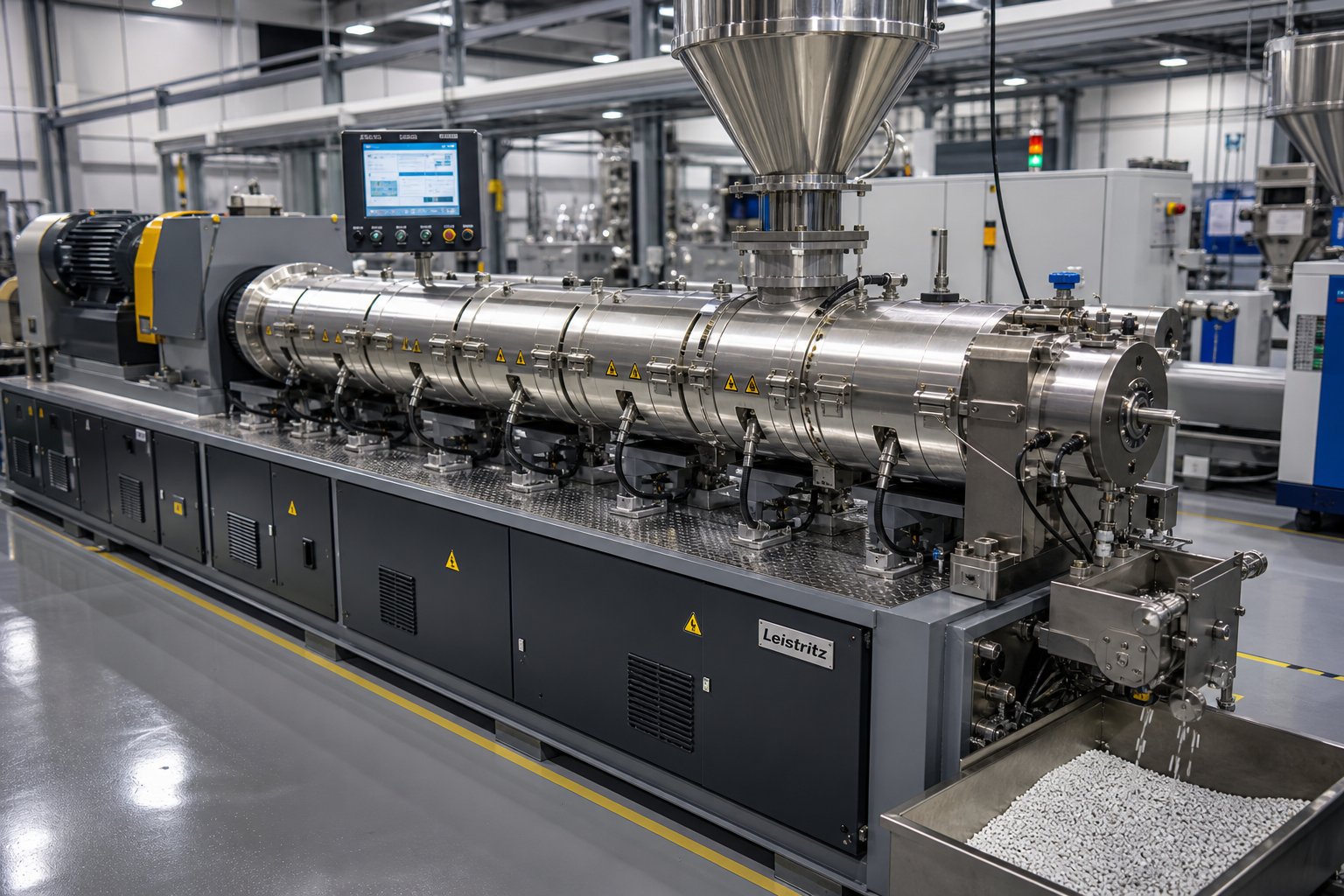
Why Twin Screw Extruders Dominate Masterbatch Manufacturing
Every masterbatch pellet starts with a deceptively simple question: how do you force pigments, fillers, or additives into a polymer melt so thoroughly that the final concentrate performs identically pellet after pellet, batch after batch? The answer, across virtually every major masterbatch facility in the world, is a co-rotating twin screw extruder.
A twin screw extruder for masterbatch is a modular, co-rotating compounding machine designed to disperse pigments, fillers, or additives into a carrier resin at high concentrations, producing pelletized concentrates used by downstream plastics processors.
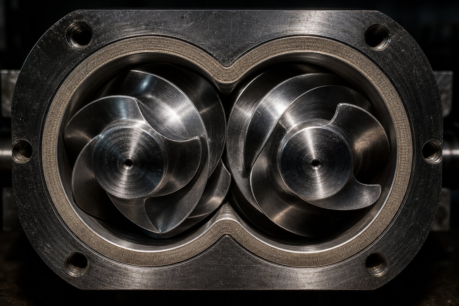
The operating principle is straightforward yet powerful. Two screws rotate in the same direction inside a closely fitted, segmented barrel. Because the screw flights intermesh, every revolution wipes one screw against the other, continuously renewing surfaces and preventing material from stagnating in dead zones. This self-wiping geometry is fundamental to both mixing performance and fast color changeovers - two priorities that define masterbatch production.
What Makes a Twin Screw Extruder the Standard for Masterbatch
Three characteristics make these machines uniquely suited for masterbatch compounding. First, the modular screw and barrel design lets engineers arrange conveying elements, kneading blocks, and mixing elements in virtually any sequence, tailoring shear intensity and residence time to each formulation. Second, the intermeshing screws deliver both dispersive mixing - breaking apart stubborn pigment agglomerates - and distributive mixing, spreading those particles uniformly throughout the melt. Third, the positive-displacement conveying action supports continuous, high-throughput processing even with heavily loaded or high-viscosity formulations.
Twin Screw vs Single Screw for Masterbatch at a Glance
Why not use a single screw extruder for masterbatch production? While single screw machines work well for simple melting and conveying tasks, they face inherent limitations when intensive compounding is required. As extrusion expert Jim Frankland explains, a twin screw can transfer the entire channel of polymer from one screw to the other multiple times, enabling full-channel mixing that a single screw simply cannot replicate. The key differences boil down to a few critical factors:
- Mixing intensity: Co-rotating twin screws generate complex, overlapping flow patterns that deliver high-shear dispersive mixing in small increments without overheating the bulk melt - single screws must force all material through restrictive mixing sections, raising temperature and reducing output.
- Throughput flexibility: Twin screws run in a starved-fed mode, decoupling screw speed from feed rate so operators can independently optimize shear and throughput for each recipe.
- Self-cleaning capability: The intermeshing flight geometry continuously wipes barrel and screw surfaces, minimizing cross-contamination and slashing color-change times - essential when a production schedule calls for dozens of formulations per week.
- Modular configurability: Screw elements can be rearranged in minutes to shift from a gentle additive blend to an aggressive pigment dispersion profile, a level of adaptability single screws cannot match.
These advantages explain why use of a twin screw extruder for masterbatch has become the industry default across color, white, black, additive, and filler concentrates alike. Yet choosing the right machine - and configuring it correctly - requires a deeper understanding of how extruder specifications, screw design, barrel temperature profiling, and downstream equipment interact to determine pellet quality. Each of those factors carries its own set of trade-offs, beginning with the unique processing demands that different masterbatch types place on the extruder.
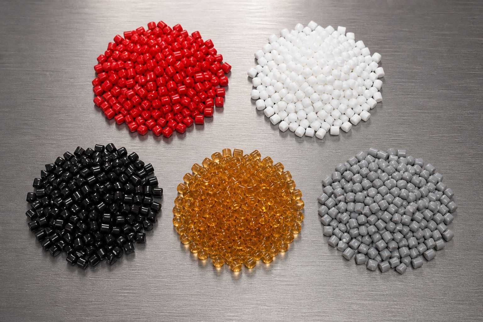
Five Masterbatch Types and Their Unique Extrusion Demands
Not all masterbatch is created equal - and the extruder settings that produce flawless color pellets can completely fail when you switch to a high-loading filler formulation. Each masterbatch category places a distinct combination of stresses on the machine, from shear sensitivity and torque demand to barrel wear and thermal limits. Understanding these differences is the first step toward choosing the right specifications and screw configuration.
Color Masterbatch Processing Requirements
Color masterbatch demands the finest dispersion of any concentrate type. Even a handful of surviving pigment agglomerates will show up as specks or streaks in a thin film or injection-molded part. The industry-standard quality gate is the filter pressure value (FPV) test, which forces the masterbatch melt through a fine screen pack and measures the pressure rise caused by undispersed particles.
Achieving a low FPV requires carefully arranged kneading blocks that generate enough shear to break apart agglomerates without degrading the pigment itself. This balancing act is especially tricky with organic pigments, which are far more shear- and heat-sensitive than their inorganic counterparts. Push the color masterbatch extrusion process too hard and you'll lose color strength; hold back too much and agglomerates survive. Typical pigment loadings range from 20% to 50%, and L/D ratios of 40:1 to 48:1 are common to accommodate multiple kneading and distributive mixing zones.
White and Black Masterbatch Challenges
White and black concentrates might seem simpler than multicolor formulations, but each presents its own processing headaches.
White masterbatch TiO2 twin screw processing involves loadings that often reach 60-70% titanium dioxide by weight. That much dense, abrasive powder demands serious torque from the gearbox and accelerates barrel and screw wear. Aggressive kneading is essential to wet every TiO2 particle, yet the sheer volume of filler acts as a heat sink, requiring higher energy input in early barrel zones to fully plasticize the carrier resin.
Carbon black masterbatch dispersion challenges are different in character but equally demanding. Carbon black particles are nano-scale, with extremely high surface energy that causes them to form tight, stubborn agglomerates. Even at modest loadings of 25-50%, the melt viscosity climbs sharply once carbon black is introduced. Breaking those agglomerates requires sustained high-shear kneading zones combined with high-torque screw configurations, and precise temperature control to prevent the carrier from degrading under the added mechanical load.
Additive and Filler Masterbatch Considerations
Additive masterbatch - carrying UV stabilizers, flame retardants, antistatics, or antioxidants - flips the processing priority. Here, the critical concern is additive masterbatch compounding temperature control. Many functional additives begin to decompose or lose effectiveness at temperatures well within the normal processing window for the carrier resin. The solution is lower barrel temperatures, shorter residence times, and minimal high-shear zones - just enough mixing to achieve uniform distribution without thermally damaging the active ingredients.
Filler masterbatch CaCO3 extrusion parameters, by contrast, are dominated by sheer volume. Calcium carbonate loadings of 70-80% mean the extruder is moving far more mineral than polymer. Side feeding becomes essential because introducing all of that powder at the main feed throat would starve the extruder of molten carrier, causing torque spikes and inconsistent output. Barrel wear resistance jumps to the top of the specification checklist, and volumetric throughput capacity often dictates the required screw diameter.
Comparing All Five Masterbatch Types at a Glance
The table below maps each masterbatch category against its typical loading range, the quality metric that matters most, the primary processing challenge, and the L/D ratio range that usually delivers the best balance of dispersion and throughput.
| Masterbatch Type | Typical Loading Range | Primary Quality Metric | Key Processing Challenge | Recommended L/D Ratio |
|---|---|---|---|---|
| Color | 20-50% | Filter pressure value (FPV) | Achieving fine dispersion without pigment degradation | 40:1 - 48:1 |
| White (TiO2) | 60-70% | Opacity / hiding power | High torque demand and abrasive barrel wear | 36:1 - 44:1 |
| Black (Carbon Black) | 25-50% | Jetness / undertone consistency | Breaking nano-scale agglomerates with high surface energy | 40:1 - 48:1 |
| Additive | 10-40% | Additive activity retention | Thermal sensitivity requiring low temperatures and short residence time | 32:1 - 40:1 |
| Filler (CaCO3) | 70-80% | Dispersion uniformity / MFI stability | Extreme volumetric loading, side feeding logistics, and barrel abrasion | 36:1 - 44:1 |
Notice how L/D ratio, torque requirements, and wear considerations shift dramatically across these five categories. A machine optimized for gentle additive blending would be hopelessly undersized for a 70% CaCO3 filler compound, and an aggressive high-shear setup built for carbon black would destroy sensitive UV stabilizers in seconds. These type-specific demands are exactly why twin screw extruder specifications - particularly L/D ratio, torque density, and screw diameter - deserve careful, formulation-driven analysis rather than one-size-fits-all selection.
Critical Extruder Specifications That Define Masterbatch Quality
Spec sheets for twin screw extruders are packed with numbers - screw diameter, maximum RPM, motor power, barrel zones - but which figures actually predict whether a machine will produce consistently excellent masterbatch? Three specifications rise above the rest: L/D ratio, torque density, and specific energy consumption. Getting these right for your formulation type is the difference between a machine that hits quality targets at full throughput and one that forces constant compromise between dispersion and output.
L/D Ratio Selection for Different Masterbatch Formulations
The twin screw extruder L/D ratio for masterbatch determines how much functional barrel length is available for melting, kneading, distributive mixing, venting, and pressure build-up. Think of it as your processing real estate - every zone you add requires physical space along the barrel.
Shorter configurations around 32:1 work well for straightforward additive dilution, where the carrier resin melts quickly and only moderate distributive mixing is needed to spread an additive uniformly. There simply isn't much de-agglomeration work to do, so a compact barrel keeps residence time short and thermal exposure low.
Demanding color or carbon black formulations tell a different story. These require aggressive kneading zones to break apart stubborn agglomerates, followed by extensive distributive mixing elements to spread particles uniformly, plus vacuum venting to strip moisture and volatiles. Fitting all of that into 32 diameters of barrel length would force impractically high screw speeds, flooding the melt with shear energy and risking thermal degradation. That's why color and black masterbatch producers commonly specify L/D ratios of 40:1 to 48:1, and some nano-filler applications push beyond 52:1.
The trade-off? Longer barrels increase total residence time and cumulative thermal load on the melt. For heat-sensitive carriers like EVA or formulations containing organic pigments, pushing past 48:1 without carefully managing temperature profiles risks discoloration or molecular weight loss. The goal is always the shortest L/D that still provides enough processing zones to hit your dispersion target - no longer.
Torque Density and Specific Energy as Performance Metrics
Imagine two extruders with identical screw diameters and the same motor power rating. One delivers its torque through a high-reduction gearbox at moderate screw speeds; the other spins faster but with less rotational force per revolution. Which produces better masterbatch? In most cases, the high-torque machine wins.
Torque density - expressed in Nm/cm3 of screw shaft cross-section - defines how much rotational force the gearbox can channel into the process. Modern co-rotating twin screw extruders achieve torque densities of up to 18 Nm/cm3, roughly 30% higher than designs from a decade ago. Higher torque density in twin screw extruder compounding enables a critical operating strategy: running at lower screw speeds while still delivering the mechanical energy needed for full de-agglomeration. Lower RPM means longer residence time per revolution, gentler shear peaks, and less viscous heating - all benefits for shear-sensitive pigments and thermally fragile additives.
Specific energy consumption in masterbatch extrusion, expressed as kWh/kg, ties all of these variables together into a single economic and quality metric. You can calculate it using a straightforward formula:
Specific Energy (kWh/kg) = [Motor Power (kW) x % Torque x (RPM running / RPM max) x Gearbox Efficiency] / Throughput (kg/h)
A lower specific energy at your target dispersion quality indicates a more efficient screw and barrel design - less wasted energy, less thermal stress on the polymer, and lower operating cost per kilogram. Tracking specific energy across production runs also provides an early warning system: if the same formulation suddenly draws 20% more energy under identical conditions, something has changed - worn screw elements, degraded feedstock, or feeder calibration drift. It's one of the most powerful troubleshooting tools available, yet surprisingly few masterbatch producers monitor it routinely.
Screw Diameter and Throughput Ranges by Masterbatch Type
Screw diameter sets the volumetric capacity of the extruder and, combined with L/D ratio and torque class, defines the throughput envelope for a given formulation. Rather than listing specifications by equipment brand, the table below organizes recommended twin screw extruder screw diameter and throughput ranges by masterbatch type - because the formulation, not the manufacturer's catalog, should drive your machine selection.
| Masterbatch Type | Recommended Screw Diameter | Preferred L/D Ratio | Minimum Torque Density | Typical Throughput Range |
|---|---|---|---|---|
| Color | 35 - 75 mm | 40:1 - 48:1 | 11.3 Nm/cm3 | 100 - 1,200 kg/h |
| White (TiO2) | 50 - 92 mm | 36:1 - 44:1 | 14+ Nm/cm3 | 200 - 2,000 kg/h |
| Black (Carbon Black) | 35 - 75 mm | 40:1 - 48:1 | 14+ Nm/cm3 | 150 - 1,500 kg/h |
| Additive | 27 - 65 mm | 32:1 - 40:1 | 11.3 Nm/cm3 | 80 - 800 kg/h |
| Filler (CaCO3 70-80%) | 50 - 135 mm | 36:1 - 44:1 | 14+ Nm/cm3 | 300 - 4,000 kg/h |
A few patterns stand out. Filler masterbatch pushes toward the largest screw diameters because moving 70-80% mineral content demands enormous free volume in the screw channels - and the torque to turn those heavily loaded screws. Color and carbon black formulations favor mid-range diameters paired with longer barrels and high torque to maximize dispersion. Additive masterbatch, with its lighter loadings and thermal sensitivity, often runs comfortably on smaller machines with shorter barrels.
These specifications set the boundary conditions for what any given extruder can achieve. But within those boundaries, the arrangement of individual screw elements - conveying flights, kneading blocks, mixing discs, and reverse elements - is where the real fine-tuning happens, shaping shear intensity, residence time distribution, and melt seal effectiveness zone by zone along the barrel.
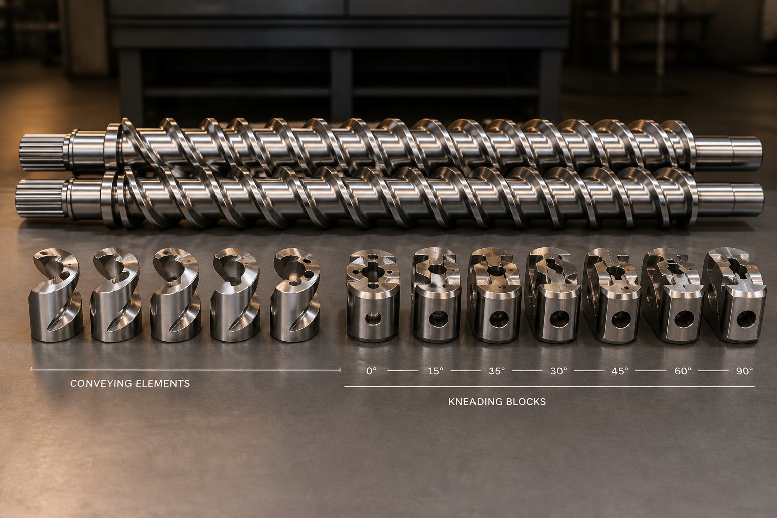
Screw Configuration and Kneading Block Design for Optimal Dispersion
Spec sheets define what an extruder can do. Screw configuration determines what it actually does. Two machines with identical diameters, L/D ratios, and torque ratings will produce vastly different masterbatch quality if their screw elements are arranged differently. This is where extruder theory meets shop-floor practice - and where experienced compounders earn their keep.
Conveying, Kneading, and Mixing Zone Layout
Imagine following a pellet of carrier resin and a cluster of pigment particles as they travel from the feed throat to the die face. The screw element configuration for masterbatch compounding creates a carefully sequenced series of environments along that path, each designed to accomplish a specific processing task.
A typical twin screw extruder screw profile design guide would map the barrel into five functional zones:
- Solid conveying zone: Large-pitch, double-flighted conveying elements quickly pull raw material away from the feed throat. The wide channels keep fill levels low and prevent bridging, especially important when feeding bulky pigment-and-resin premixes.
- Melting and dispersive mixing zone: Narrow-pitch conveying elements slow the material, increasing fill level and pressure. Kneading blocks then take over, applying intense shear and elongational stress to melt the carrier resin and simultaneously break apart pigment or filler agglomerates.
- Distributive mixing zone: Tooth-type (ZME), turbine, or screw mixing elements (SME) take the now-dispersed particles and spread them uniformly throughout the melt matrix. These elements generate complex flow patterns with lower peak shear than kneading blocks, which prevents re-agglomeration.
- Melt seal and venting zone: Reverse-pitch conveying elements or reverse kneading blocks create a fully filled melt plug that seals upstream pressure from the downstream vacuum vent. Without this seal, atmospheric or vacuum venting can't remove moisture and volatiles effectively.
- Pressure build-up zone: Tight-pitch conveying elements compress the melt and push it through the screen pack and die, building sufficient head pressure for consistent strand formation or underwater pelletizing.
The real art lies in the kneading blocks. The twin screw extruder kneading block stagger angle - the angular offset between successive kneading discs - is the single most powerful variable for controlling shear intensity and residence time within a mixing zone. Here's how the common stagger angles compare:
- 30-degree stagger: Strong forward-conveying action with mild mixing. Material passes through quickly, experiencing minimal shear. Best used where gentle blending is sufficient or as a transition between zones.
- 45-degree stagger: Moderate mixing with reduced forward conveyance compared to 30-degree blocks. A practical middle ground for formulations that need meaningful shear without the intensity of wider angles.
- 60-degree stagger: Significantly stronger mixing with weaker conveying. Fill level rises, residence time in the kneading zone increases, and agglomerates experience more shear events per unit length.
- 90-degree stagger (neutral): Zero net conveying - the block produces 100% fill and maximum mixing intensity. These are the workhorses for dispersive mixing of stubborn pigments like carbon black and phthalocyanine blues. However, they also generate the most viscous heating, so they must be used judiciously.
Disc thickness adds another layer of control. Thinner kneading discs at the same stagger angle create more flow interruptions per unit length, intensifying the mixing effect. Thicker discs provide smoother, gentler kneading - a useful distinction when fine-tuning a profile for shear-sensitive organic pigments.
Tailoring Screw Profiles by Masterbatch Type
No single screw profile works for every masterbatch. The processing demands outlined in earlier sections translate directly into element-by-element layout decisions. Here's how the profiles diverge:
- Color masterbatch: Requires aggressive kneading early in the barrel - typically two or three sets of 60-degree and 90-degree kneading blocks to fully de-agglomerate pigment clusters - followed by an extended distributive mixing section using tooth-type or turbine elements. This sequence ensures that particles are first broken down to sub-critical sizes and then evenly distributed, achieving the low filter pressure values that buyers demand.
- Filler masterbatch (CaCO3 at 70-80%): Needs a gentler upstream melting section because the carrier resin must be fully plasticized before the mineral filler is introduced via a downstream side feeder. Placing aggressive kneading blocks upstream of the side feeder port would grind abrasive filler against unmelted resin and barrel walls, accelerating wear dramatically. The kneading intensity after the side feeder should be moderate - enough to wet the filler surface but not so intense that it generates excessive heat or barrel erosion.
- Additive masterbatch: Benefits from minimal high-shear zones. Many functional additives - UV stabilizers, hindered amine light stabilizers, certain flame retardants - begin to decompose when subjected to prolonged high-shear kneading. A profile with short 30-degree or 45-degree kneading sections and extended distributive mixing elements preserves additive activity while still achieving homogeneity in the final pellet.
- Black masterbatch (carbon black): Demands sustained high-intensity kneading - often longer kneading block sequences than color masterbatch - because nano-scale carbon black agglomerates have extremely high surface energy. Multiple sets of 60-degree and 90-degree blocks, potentially with thin disc widths, are typically arranged in series with short conveying spacers between them to allow pressure relaxation and prevent the melt from overheating.
- White masterbatch (TiO2): Sits between color and filler profiles. The high loading requires robust torque, but TiO2 is less abrasive than CaCO3, so moderately aggressive kneading is tolerable. The critical concern is ensuring every particle is fully wetted by the carrier, which favors a combination of strong kneading followed by distributive mixing elements rather than relying on kneading alone.
Scaling Screw Configurations from Lab to Production
You've perfected a screw profile on a 20 mm benchtop twin screw extruder. The color is gorgeous, FPV is well within spec, and pellet quality looks flawless. Then you move to a 65 mm production machine - and the results fall apart. Sounds familiar? This is the scale-up challenge that trips up even experienced compounders.
The difficulty arises because scaling up a twin screw extruder from lab to production isn't a simple matter of building a bigger copy. As Technovel's engineering team explains, two competing scaling laws govern the process. The cubic law (Q proportional to D cubed) maximizes throughput gains - scaling from a 15 mm to a 60 mm screw yields a theoretical 64x increase in volumetric capacity. The square law (Q proportional to D squared) preserves thermal and shear history but limits the throughput multiplier to about 16x. Real-world scale-ups land somewhere between these two extremes.
Three parameters must be carefully matched when transferring a screw profile from a small machine to a larger one:
- Tip speed: The peripheral velocity of the screw flight determines peak shear rate at the barrel wall. A 20 mm screw running at 600 RPM has a far lower tip speed than a 65 mm screw at the same RPM. To preserve the same shear environment, the production machine typically runs at significantly lower RPM - a relationship governed by screw diameter ratio.
- Specific torque: Torque per unit of cross-sectional area must be sufficient on the larger machine to handle the proportionally greater volume of material. If the production gearbox can't deliver equivalent specific torque, dispersion quality degrades even with an identical element layout.
- Free volume ratio: The open channel area available for material scales with the cube of the diameter, but heat transfer surface only scales with the square. This geometric mismatch means larger machines struggle to remove shear-generated heat as effectively as small ones. The practical consequence? A screw profile that ran cool on the lab machine may cause thermal degradation at production scale unless barrel cooling capacity is enhanced or kneading intensity is slightly reduced.
The safest approach is to conduct pilot-scale trials on an intermediate machine size - say 35 mm - before committing to a full production configuration. This intermediate step reveals heat transfer and fill behavior issues that a direct jump from benchtop to production would only expose after expensive commissioning runs.
Screw configuration, however, doesn't operate in isolation. Every kneading block and mixing element interacts with the thermal environment along the barrel - and managing that temperature profile zone by zone is what separates a good masterbatch from a great one.
Barrel Temperature Profiling and Carrier Resin Interactions
A perfectly configured screw can still produce disappointing masterbatch if the thermal environment along the barrel is working against it. Barrel zone temperatures shape how quickly the carrier resin melts, how much shear energy converts to heat, and whether pigments or additives survive the trip from feed throat to die. Yet the twin screw extruder barrel temperature profile for masterbatch is one of the most under-discussed topics in compounding literature - often reduced to a single line on a process sheet rather than treated as the formulation-specific engineering decision it actually is.
Setting Temperature Zones for PE, PP, PS, and EVA Carriers
The general principle is intuitive: barrel temperatures should create a controlled melting gradient that fully plasticates the carrier resin without overshooting into degradation territory. In practice, though, the right profile varies dramatically depending on carrier resin chemistry.
Consider LDPE and EVA, both relatively low-melting, forgiving polymers. The feed zone stays well below the melting point - typically 40-80 degrees C - to maintain solid conveying friction against the barrel wall. Without that friction differential, pellets would simply rotate with the screws instead of being pushed forward. Temperatures then ramp above the melt point through the kneading and mixing zones, reaching 150-180 degrees C at the die.
PP and PS carriers require a different approach. Polypropylene's higher crystalline melting point (around 160-170 degrees C) and its tendency toward oxidative degradation at elevated temperatures demand a steeper but carefully controlled ramp. Polystyrene, being amorphous, has no sharp melting point but does have a narrower processing window before thermal degradation begins - especially high-impact grades where the rubber phase is sensitive to excessive heat. As extrusion training resources note, the processing temperature for typical semi-crystalline materials should be set roughly 50-75 degrees C above the melting temperature, while amorphous materials typically process at about 100 degrees C above the glass transition temperature.
The table below shows representative temperature zone settings for PE, PP, PS, and EVA carrier resins across a five-zone barrel layout. These values serve as starting points - actual settings depend on formulation, filler loading, screw configuration, and machine-specific heat transfer characteristics.
| Barrel Zone | LDPE Carrier | PP Carrier | PS (HIPS) Carrier | EVA Carrier |
|---|---|---|---|---|
| Feed zone | 40 - 60 degrees C | 60 - 80 degrees C | 50 - 70 degrees C | 30 - 50 degrees C |
| Melting zone | 120 - 150 degrees C | 180 - 210 degrees C | 170 - 200 degrees C | 100 - 130 degrees C |
| Mixing zone | 150 - 170 degrees C | 200 - 220 degrees C | 190 - 210 degrees C | 120 - 150 degrees C |
| Metering zone | 150 - 165 degrees C | 200 - 215 degrees C | 185 - 205 degrees C | 120 - 145 degrees C |
| Die | 155 - 175 degrees C | 200 - 220 degrees C | 190 - 210 degrees C | 125 - 150 degrees C |
You'll notice that EVA profiles run the coolest overall - its low softening point and crosslinking sensitivity punish excessive temperatures. PP profiles, by contrast, require the most aggressive ramp from feed to melt zone, reflecting the energy needed to disrupt its crystalline structure. PS profiles sit in between but demand careful attention in downstream zones, where prolonged high temperatures can degrade the butadiene rubber component in HIPS grades.
How Pigment and Filler Loading Affects Temperature Strategy
Carrier resin chemistry sets the baseline profile, but the pigments and fillers riding along in the melt matrix can force significant adjustments.
High filler loadings - think 60% or more of CaCO3 or TiO2 - act as massive heat sinks. All that mineral powder absorbs thermal energy without contributing to the melt viscosity drop that helps material flow. The practical consequence is that early barrel zones may need to run 10-20 degrees C hotter than a neat resin profile would suggest, simply to deliver enough energy to fully plasticize the limited carrier fraction. Operators who ignore this high filler loading temperature strategy in the extruder often end up with unmelted resin fragments embedded in the pellet, which show up immediately in drawdown or film tests.
Heat-sensitive organic pigments push the profile in the opposite direction. Downstream of the primary kneading zone, where most dispersive work is already done, a flat or even slightly descending temperature profile protects pigments like quinacridone reds and diarylide yellows from thermal degradation that would dull their color strength or shift their hue. Rather than ramping temperatures upward all the way to the die, experienced operators hold or slightly reduce set points in the distributive mixing and metering zones.
Vacuum venting zones deserve special attention. If the barrel temperature around the vent port is too high, the polymer melt becomes too fluid and can be drawn into the vent opening by the applied vacuum - a messy and costly problem known as "vent flow." Keeping the vent zone temperature slightly below the mixing zone set point increases melt viscosity just enough to resist the vacuum pull while still allowing moisture and volatiles to escape.
Interaction Between Barrel Temperature and Screw Speed
Here's a concept that separates experienced operators from beginners: the energy driving polymer melting and mixing comes from two distinct sources, and you can shift the balance between them.
Barrel heaters supply conductive energy - heat flowing from the barrel wall into the melt. Screw rotation generates dissipative (shear) energy - mechanical work converted into heat through viscous friction within the polymer itself. When you reduce barrel temperature set points while increasing screw speed, you shift the energy balance from conductive toward dissipative. This barrel temperature vs screw speed extrusion balance is a powerful tuning lever because shear energy delivers heat directly where it's needed - at the interface between agglomerates and melt - rather than relying on slow conduction from the barrel wall inward.
The potential benefit? Improved dispersion at lower average melt temperatures, because the shear energy targets the high-viscosity zones around agglomerates more effectively than wall-conducted heat. The risk? Localized overheating at kneading block tips, where shear rates peak, even though the bulk melt temperature reads within specification. This mismatch between measured melt temperature and actual peak temperature at the screw tip is exactly the phenomenon that researchers at Dow have documented when studying screw root temperatures - the sensors can't capture the full thermal picture.
The practical takeaway? Adjusting screw speed and barrel temperature in tandem - rather than independently - is the most effective way to fine-tune the thermal profile for each masterbatch formulation. Small, deliberate shifts in both variables simultaneously let you dial in dispersion quality without pushing either the carrier resin or the sensitive ingredients past their limits. This kind of process finesse becomes especially important in the step-by-step workflow of actual masterbatch production, where every upstream decision cascades into downstream pellet quality.
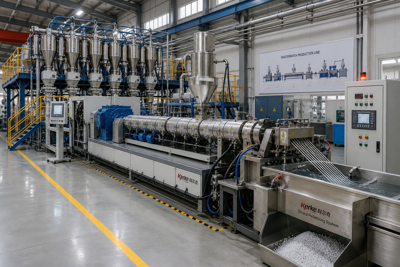
The Complete Masterbatch Extrusion Process Step by Step
Specifications, screw profiles, and temperature maps are essential planning tools - but what actually happens on the production floor when raw pigment, carrier resin, and additives transform into uniform masterbatch pellets? Following the material through every stage, from the mixer to the pelletizer, reveals how each upstream decision shapes the final product. This masterbatch extrusion process step by step walkthrough connects the engineering theory covered so far to the physical reality inside your plant.
Pre-Mixing, Drying, and Gravimetric Feeding
Production begins long before the extruder motor starts. Most color and additive masterbatch formulations require pre-blending in a high-speed mixer - typically a Henschel-type unit spinning at 1,000 to 3,000 RPM. This step coats carrier resin pellets or powder with a thin layer of pigment and any processing aids, improving feed consistency and reducing the dispersive work the extruder must perform later.
Hygroscopic carrier resins like PA or PET require drying before processing. Even modest moisture levels - as little as 0.05% in polyamide - can trigger hydrolytic degradation inside the barrel, destroying molecular weight and producing porous, brittle pellets. Desiccant dryers or vacuum dryers bring moisture content below the critical threshold before the material ever reaches the feed hopper.
Gravimetric feeding on a twin screw extruder for masterbatch is where formulation accuracy lives or dies. Loss-in-weight feeders continuously measure and adjust the mass flow of each ingredient, holding the pigment-to-carrier ratio within tight tolerances - typically plus or minus 0.5% or better. As Coperion's masterbatch process documentation highlights, the split-feed process uses individual gravimetric feeders for each component, with polymer entering the main feed barrel and pigments introduced gently via a twin screw side feeder downstream of the melting zone.
When is side feeding essential rather than optional? High-loading filler masterbatch provides the clearest example. Introducing 70-80% CaCO3 at the main feed throat would overwhelm the limited carrier resin fraction, starving the screws of melt lubrication and causing severe torque spikes. Side feeders positioned after the carrier is fully molten solve this by introducing filler into an already-plasticized matrix, allowing smooth incorporation without overloading the drive system.
Melting, Dispersive Mixing, and Distributive Mixing Inside the Barrel
Once material enters the barrel, it passes through a precisely orchestrated sequence of processing environments. The journey begins in the solid conveying zone, where screw flights drag pellets and powder forward through friction against the barrel wall. Within the first few diameters, barrel heat and inter-particle friction begin softening the carrier resin.
True melting occurs in the kneading zone. Here, closely stacked kneading blocks compress and shear the softening polymer, converting mechanical energy into heat far more efficiently than barrel conduction alone. The carrier transitions from a partially solid mass to a continuous melt - and this is where the critical distinction between dispersive vs distributive mixing in masterbatch compounding begins to play out.
Dispersive mixing applies intense localized stress to break agglomerates below a critical particle size. Imagine a cluster of carbon black nanoparticles bound together by van der Waals forces - the kneading blocks must generate shear stresses exceeding those cohesive forces to fracture the agglomerate into its primary particles. This requires high energy density concentrated at narrow clearances between kneading disc tips and the barrel wall.
Distributive mixing, by contrast, spreads the already-dispersed particles uniformly throughout the melt matrix. Tooth-type mixing elements and turbine geometries repeatedly split and recombine the melt stream, eliminating concentration gradients without applying excessive shear. As industrial extrusion references explain, a compounding line may need strong dispersive mixing to break pigment agglomerates, extensive distributive mixing to spread them evenly, or both - and the screw configuration must deliver each type at the right stage of melt development.
Between the mixing zones and the die, a melt seal created by reverse elements isolates the upstream pressure from a vacuum vent port. This venting step removes residual moisture, entrained air, and low-molecular-weight volatiles. Skipping or under-sizing this zone is a fast track to porous pellets, surface defects, and inconsistent melt flow index in the finished masterbatch.
Filtration, Pelletizing, and Quality Testing
The melt exiting the barrel passes through a screen pack - a stack of woven metal meshes held in a breaker plate - before reaching the die. Screen mesh selection involves a direct trade-off: finer meshes (200+ mesh count) catch smaller agglomerates but generate higher back pressure; coarser meshes (80-120 mesh) allow faster throughput but let marginal particles pass. Many producers use a graduated stack - coarse support screens on the upstream side and a fine filtration screen on the downstream side - to balance pressure drop against filtration effectiveness.
Beyond filtration, the screen pack doubles as a real-time dispersion validation tool. A rapidly rising pressure across the screen indicates that under-dispersed agglomerates are plugging the mesh faster than expected - a direct signal that something upstream needs attention, whether it's kneading intensity, feeder accuracy, or screw element wear.
After filtration, the melt reaches the pelletizing system. Choosing between masterbatch pelletizing methods - strand vs underwater or water-ring - depends on throughput, pellet geometry requirements, and the carrier resin's behavior at the die:
- Strand pelletizing: The melt exits as multiple strands through a multi-hole die, passes through a water cooling trough, and enters a strand cutter. Preferred for lower-volume production, frequent color changes, and formulations where visual inspection of the strand quality provides valuable process feedback.
- Water-ring pelletizing: Strands are cut at the die face inside a water-filled chamber. Produces cylindrical pellets with rounded edges and handles moderate throughput ranges well. A practical middle ground for masterbatch producers needing faster output than strand cutting without the capital cost of a full underwater system.
- Underwater pelletizing: The melt is cut into droplets directly at the die face by rotating blades submerged in pressurized water, producing uniform, spherical micro-pellets. Preferred for high-throughput operations, compounds requiring consistent pellet geometry for downstream dosing accuracy, and formulations with sticky or low-viscosity melts that would struggle in strand form.
The finished pellets then face a battery of quality tests - each one traceable back to specific extruder parameters:
- Filter pressure value (FPV) test: The gold standard for dispersion quality in color masterbatch. As described by Collin Solutions' technical documentation, the filter pressure value test for masterbatch quality works by melting the sample in a small extruder, pumping it at a constant volume flow through a standardized screen, and measuring the pressure rise caused by undispersed particles. A lower FPV indicates better dispersion - and directly reflects the effectiveness of the kneading block arrangement and screw speed settings on the production extruder.
- Drawdown test: A thin film is produced from the masterbatch let-down ratio, then examined for specks, streaks, or un-dispersed particles. Failures here point to insufficient dispersive mixing or worn screw elements that have lost their tight clearances.
- Color strength measurement: Spectrophotometric comparison against a reference standard. Batch-to-batch shifts in color strength often trace back to feeder accuracy drift or barrel temperature inconsistencies that subtly alter pigment wetting.
- Melt flow index (MFI) consistency: Measures the viscosity of the masterbatch under standard conditions. Variations in MFI between production lots can indicate changes in residence time, thermal degradation from excessive barrel temperatures, or inconsistent filler loading from gravimetric feeder calibration errors.
Every one of these test results is, in effect, a report card on the upstream process. A failing FPV doesn't just mean "bad dispersion" - it means something specific went wrong in the kneading zone, the feed system, or the temperature profile. Recognizing which upstream variable drives each downstream test result is what transforms reactive troubleshooting into proactive quality control - and that troubleshooting discipline is where many masterbatch operations have the most room to improve.
Common Mistakes That Ruin Masterbatch Quality and How to Fix Them
Quality test failures rarely appear without warning. They build quietly - a filter pressure value creeping upward over a few shifts, pellet color drifting slightly off-spec, or strand breakage becoming a little more frequent at the die. By the time someone flags the problem, the root cause has often been active for hours or days. Effective masterbatch extrusion troubleshooting for poor dispersion, output instability, and degradation starts with recognizing the patterns that connect shop-floor symptoms to specific upstream causes.
Dispersion Failures and Their Root Causes
Pigment dispersion failure root cause analysis almost always leads back to one of three problems - and each demands a different corrective action.
Undispersed agglomerates (high FPV, specks in drawdown film): The most common culprit is insufficient kneading intensity. Either the screw profile lacks enough 60-degree or 90-degree kneading blocks, or the blocks have been positioned too far downstream where the melt viscosity has already dropped too low to generate adequate shear stress on the agglomerates. The fix? Reposition or add kneading blocks closer to the melting zone, where viscosity is still high enough to transmit shear forces into particle clusters. Paradoxically, running screw speed too high can also cause poor dispersion - excessive RPM reduces fill level in the kneading zone, allowing material to slip past without experiencing full shear. As industry process engineers have documented, both screw configuration and screw speed are closely related to shear dispersion and must be considered as an integrated whole.
Unmelted gels (hard spots visible in film or strand): These are fragments of carrier resin that never fully plasticized. The root cause is typically an inadequate melting zone - either the kneading section is too short, barrel temperatures in the melting zone are set too low, or the feed rate exceeds the extruder's melting capacity at the current screw speed. Corrective action starts with verifying that melting zone temperatures sit at least 20-30 degrees C above the carrier resin's melting point, and that the kneading block sequence in the compression zone is long enough to convert all incoming solids before the material reaches the mixing section.
Inconsistent color batch to batch: When the same formulation produces subtly different color strength or hue between production runs, the problem usually lives in the feeding system or in accumulated screw wear. Gravimetric feeder calibration drift of even 1-2% on the pigment channel can produce visible color shifts in sensitive formulations. Equally insidious is gradual screw element wear - as kneading block tips erode and clearances widen, the shear profile quietly degrades, reducing dispersion efficiency so slowly that operators compensate with speed adjustments without realizing the underlying cause has changed.
Output Instability and Thermal Degradation
Twin screw extruder output surging - cyclic fluctuations in strand diameter or pellet weight - frustrates operators because the machine appears to be running normally between surges. The causes and fixes depend on where in the process the instability originates:
- Surging from inconsistent feeding: Material bridging in the hopper, loss-in-weight feeder oscillation, or erratic side feeder delivery all produce flow interruptions that propagate through the barrel as pressure waves. The corrective action is straightforward - clean the feed system, recalibrate the feeder, and verify that hopper agitators are functioning. For side-fed filler masterbatch, ensure the side feeder screw speed is properly ratioed to the main extruder throughput.
- Surging from improper melt seal: If the reverse elements creating the melt seal before the vent port are worn or incorrectly sized, the seal becomes intermittent. Melt periodically breaks through, disrupting pressure stability downstream. Replacing worn reverse elements or adding an additional reverse kneading block to strengthen the seal usually resolves the issue.
- Die drool: That annoying buildup of degraded polymer at the die lip - forming brown or black deposits that periodically break off and contaminate the strand - signals excessive residence time or over-temperature somewhere in the barrel. The degraded material accumulates at the low-velocity boundary layer near the die exit. Reducing the temperature in the last barrel zone and die by 5-10 degrees C, or increasing throughput to shorten residence time, typically eliminates the problem. Persistent die drool despite temperature adjustments may indicate dead spots in the die design itself.
- Rapidly rising filter pressure: When the screen pack pressure climbs faster than expected, either the dispersion is failing upstream (agglomerates clogging the mesh) or contaminants have entered the raw material stream. Distinguishing between the two requires pulling the screen pack and examining the residue - pigment agglomerates look distinctly different from foreign particle contamination under magnification.
Common Twin Screw Extruder Operator Mistakes to Avoid
After years of production-floor experience, certain mistakes appear again and again across different plants and product lines. Ranked by their impact on masterbatch quality, here are the most damaging errors:
- Overfeeding pigment before the carrier is fully molten. Introducing high concentrations of dry pigment into an incompletely plasticized resin means the agglomerates never experience the melt viscosity needed to transmit shear stress. The pigment essentially rides through the kneading zone without being properly wetted or dispersed. The solution is to ensure the carrier resin is fully molten before the pigment-rich feed reaches the first kneading block - which may require adjusting the feed port location or increasing early-zone barrel temperatures.
- Insufficient venting causing porosity in pellets. When vacuum vent ports are partially blocked by polymer buildup, or when vacuum levels drop below the target range, moisture and volatiles remain trapped in the melt. The result is foamed or porous pellets that fail density and appearance specifications. Regular vent port cleaning and vacuum level monitoring prevent this entirely avoidable defect.
- Using the wrong screen pack mesh size. Too fine a mesh creates excessive back pressure that slows throughput and extends residence time, potentially causing thermal degradation. Too coarse a mesh lets marginal agglomerates pass through, producing masterbatch that will fail the customer's own quality tests. As process specialists caution, relying solely on the filter mesh to guarantee product quality - instead of addressing dispersion problems at the source - leads to frequent filter changes, increased downtime, and material degradation from extended high-temperature residence.
- Neglecting barrel and screw element wear. Wear happens gradually. A kneading block that loses 0.1 mm of tip clearance over several weeks won't trigger any alarm, but the cumulative loss of shear intensity silently degrades dispersion quality. By the time the FPV test catches the problem, the screws may need significant rebuilding. Implementing a regular inspection schedule - measuring screw element diameters with a micrometer at defined intervals - catches wear before it reaches the quality-critical threshold.
- Failing to match kneading intensity to the specific pigment or filler type. Running an aggressive carbon black screw profile when switching to a shear-sensitive organic pigment will thermally degrade the colorant and shift the hue. Conversely, using a gentle additive profile for a high-structure carbon black will produce unacceptable dispersion. Every formulation change should prompt a review of whether the current screw configuration matches the new material's processing requirements - a step that gets skipped surprisingly often under production time pressure.
These five mistakes share a common thread: they all stem from treating the extruder as a static machine rather than a dynamic system that must be tuned to each formulation and monitored continuously. Recognizing which variables to watch - and knowing what the symptoms mean - is the foundation of consistent quality. With that troubleshooting discipline in place, the next challenge becomes strategic: choosing the right extruder in the first place, so the machine's capabilities match the production demands it will face for years to come.
How to Select the Right Twin Screw Extruder for Masterbatch Production
Knowing how to troubleshoot an extruder is valuable. Knowing how to select the right one in the first place is worth far more - because the wrong machine locks you into compromises that no amount of process optimization can overcome. Yet the selection process at many masterbatch operations boils down to comparing price quotes and maximum throughput claims, two metrics that tell you almost nothing about whether a machine will actually meet your quality and cost targets over a five- to ten-year service life.
A more effective approach treats machine selection as an engineering evaluation rather than a purchasing exercise. The twin screw extruder buyer evaluation checklist below focuses on the specifications that directly predict performance in masterbatch compounding - and explains why each one matters more than the headline numbers on a brochure.
Key Selection Parameters Beyond Price
Imagine two extruders side by side at a trade show. One boasts 1,200 RPM maximum screw speed. The other tops out at 900 RPM. Which is better for masterbatch? The honest answer: you can't tell from that number alone. Maximum RPM is a mechanical limit, not a processing recommendation - most masterbatch runs at a fraction of the rated speed. The specifications that actually predict day-to-day performance are less glamorous but far more revealing:
- Torque density (Nm/cm3): Determines how much mechanical energy the gearbox can deliver into the melt at any given screw speed. Higher torque density lets you run slower with more force per revolution - critical for high-viscosity formulations like 70% CaCO3 filler or carbon black masterbatch. A machine rated at 14+ Nm/cm3 gives you headroom; one at 8 Nm/cm3 will hit torque limits on demanding recipes and force you to reduce feed rate.
- Specific throughput (kg/h per RPM): Reveals how efficiently the screw geometry converts each revolution into actual output. A higher value means you reach your production target at lower screw speeds, reducing shear-generated heat and extending the processing window for thermally sensitive formulations.
- Free volume: The open cross-sectional area inside the barrel available for material. Larger free volume accommodates bulky, low-density feeds - think pre-blended pigment-and-resin mixtures or fluffy CaCO3 powder - without starving the screws. It's especially relevant when evaluating how to select a twin screw extruder for masterbatch involving high-loading filler formulations.
- Specific energy consumption (kWh/kg at target dispersion): As discussed in the specifications chapter, this metric ties together motor power, torque, screw speed, and throughput into a single efficiency indicator. Comparing specific energy across candidate machines - using the same test formulation - reveals which screw and barrel design delivers the required dispersion with the least wasted energy and thermal stress.
- Number and configurability of barrel zones: More independently controlled heating and cooling zones give you finer control over the temperature profile. For masterbatch producers running multiple carrier resins (PE, PP, PS, EVA), the ability to shape different thermal gradients across the same barrel length is a practical necessity, not a luxury.
- Availability of side feeders and downstream integration: If your product mix includes filler masterbatch at 70%+ loading, the extruder must accommodate at least one downstream side feeder port with sufficient barrel opening and screw conveying capacity. Equally important is compatibility with your preferred pelletizing system - strand, water-ring, or underwater - and the ease of integrating gravimetric feeding, screen changers, and diverter valves.
When you evaluate machines against these criteria rather than peak RPM or nameplate motor power, the field narrows quickly. You'll find that some attractively priced machines lack the torque density for your heaviest formulations, while others offer more barrel zones and free volume than you'll ever use - costing extra capital without adding value.
Evaluating Barrel and Screw Wear Solutions for High-Abrasion Applications
Here's a cost factor that almost never appears in the initial equipment quote but can dominate your total cost of ownership within two years: barrel and screw element wear.
For additive or standard color masterbatch on polyolefin carriers, wear is manageable. A properly nitrided barrel with a surface hardness of 950-1100 HV and a case depth of 0.4-0.6 mm can deliver several years of service before the bore opens up enough to affect dispersion quality. But switch to a high-loading filler formulation - 70% CaCO3, BaSO4, or talc - and the equation changes dramatically. Abrasive mineral particles grinding against the barrel bore at every screw revolution can penetrate a nitrided case in 12-18 months, exposing the softer core steel and accelerating wear non-linearly from that point forward.
As engineering comparisons between barrel metallurgies document, the effective wear reserve of a bimetallic barrel is five to six times greater than a nitrided surface - 1.5 to 3.0 mm of homogeneous alloy liner versus 0.5 mm of hardened case. In abrasive service, bimetallic barrels typically last two to three times longer under moderate wear and three to seven times longer under severe wear conditions, making the initial 2-3x price premium a clear winner on total cost per operating hour.
The critical selection factors when sourcing twin screw extruder barrel wear resistant solutions include:
- Metallurgical options: Iron-based (Fe-Cr-B) liners suit general CaCO3 and talc abrasion at 58-62 HRC. Nickel-based (Ni-Cr-B-W) liners add corrosion resistance for flame retardant or PVC-based formulations at 60-65 HRC. Tungsten-carbide-rich liners deliver the highest abrasion resistance at 65-70 HRC for extreme glass fiber or high-mineral applications.
- Dimensional precision: A replacement barrel must match the original bore diameter, screw-to-barrel clearance, and flange geometry within tight tolerances. Bore straightness should hold 0.015 mm/m or better, and surface roughness after honing should be Ra 0.4 micrometers or less. Out-of-spec barrels create uneven clearance that concentrates wear in localized zones and degrades dispersion uniformity.
- Compatibility with existing extruder frames: Not every parallel twin screw barrel replacement is a drop-in fit. Feed port locations, thermocouple positions, barrel heating jacket interfaces, and bolt patterns must align with the original machine design. Producers sourcing replacement or custom parallel twin screw barrels - such as those available from NANHAIYA - should verify that the supplier offers nitrided, bimetallic, and tungsten carbide lined options with confirmed dimensional compatibility for their specific extruder model.
- Supplier responsiveness and lead time: A worn-out barrel sitting on a production extruder costs real money every shift. Replacement lead times of 5-8 weeks for bimetallic barrels are standard across the industry, so maintaining a spare barrel for your most-used configurations - or identifying a supplier with shorter turnaround capability - is a practical hedge against unplanned downtime.
For operations running abrasive filler masterbatch as a significant portion of their product mix, barrel replacement frequency and cost-per-bore-hour should sit alongside extruder purchase price as a primary decision criterion. A machine with a lower sticker price but no readily available abrasion-resistant barrel options will cost far more over five years than a higher-priced machine backed by a responsive barrel supply chain.
Matching Extruder Size to Production Volume
Screw diameter is the single specification that most directly determines throughput capacity. As capacity calculation guides explain, output scales roughly with the square of the screw diameter - doubling the diameter yields approximately four times the volumetric throughput capacity, not two. This non-linear relationship means that oversizing or undersizing by even one frame class can have outsized consequences.
Undersizing forces higher screw speeds to meet throughput targets, which increases shear heating, shortens residence time, and pushes the gearbox closer to its torque limits. Oversizing wastes capital and can actually hurt quality - an extruder running at very low fill levels produces inconsistent mixing because the kneading blocks can't generate sufficient pressure on the sparse material.
A practical sizing approach works backward from your realistic annual volume targets:
- Calculate required hourly throughput: Divide annual volume by planned operating hours (typically 5,000-7,000 hours per year for a two- or three-shift operation). Add 15-20% margin for color changes, startups, and maintenance downtime.
- Match to screw diameter class: Use vendor-neutral throughput ranges for your masterbatch type - the specification table from the earlier chapter provides a starting framework. For example, a color masterbatch producer needing 400 kg/h sustained output would look at 50-65 mm screw diameters, while a filler masterbatch operation targeting 2,000 kg/h would evaluate 92-135 mm machines.
- Verify L/D ratio against product mix: If your production schedule includes both simple additive blends (32:1 L/D sufficient) and demanding carbon black formulations (44:1+ L/D needed), size the barrel for the most demanding product. Running a simpler formulation on a longer barrel is a minor inefficiency; trying to run a complex formulation on a barrel that's too short is a quality failure.
- Start with lab-scale trials: Before committing to a production-class extruder, validate your formulations on a benchtop or pilot machine in the 16-35 mm range. As discussed in the scale-up section, these trials establish baseline screw profiles, temperature maps, and specific energy targets that transfer - with appropriate scaling adjustments - to the full-size machine. The investment in trial material and lab time is trivial compared to the cost of discovering on a commissioned 75 mm extruder that your formulation needs a fundamentally different screw layout.
Ultimately, selecting the right twin screw extruder for masterbatch production means aligning every specification - torque density, free volume, L/D ratio, barrel metallurgy, and screw diameter - against the specific demands of your actual product portfolio, not against a theoretical "average" formulation. A machine chosen through this kind of disciplined, formulation-driven evaluation will deliver consistent quality at target throughput for years. A machine chosen on price or peak specs alone will spend those same years teaching you expensive lessons about the compromises hiding behind the numbers.
Future Trends and Sustaining Masterbatch Extrusion Performance
A well-selected, properly configured twin screw extruder is a long-term asset - but neither the technology nor the market stands still. The machines themselves are evolving, the raw materials they process are shifting toward sustainability, and the daily reality of wear and degradation quietly erodes even the best-performing setup. Staying ahead of these forces is what separates masterbatch producers who maintain consistent quality year after year from those who find themselves perpetually chasing yesterday's performance.
Emerging Innovations in Twin Screw Extrusion for Masterbatch
The most impactful twin screw extruder masterbatch industry trends center on gearbox technology, competitive alternatives to the masterbatch format itself, and the rise of non-traditional carrier resins.
High torque density gearboxes are reshaping what's possible on a given frame size. Where a 65 mm extruder a decade ago might have delivered 11 Nm/cm3 per shaft, the latest gearbox designs push that figure to 14 Nm/cm3 and beyond. As Zambello Group's engineering team reports, their ZT range for co-rotating twin screw extruders now delivers torque density up to approximately 14 Nm/cm3 per shaft, enabling higher throughputs in compounding and masterbatch production with compact footprints. The practical benefit for masterbatch producers is significant: a high torque density gearbox on a twin screw extruder lets you process demanding formulations - 70% CaCO3 filler, high-structure carbon black - on a smaller, less capital-intensive machine than previously required. Or it gives you headroom on an existing frame to push throughput without hitting torque limits that force feed rate reductions.
Direct coloring - dosing liquid or powder colorants directly at the injection molding or film extrusion machine, skipping the masterbatch step entirely - has gained traction in certain high-volume, single-color applications. Should masterbatch producers be worried? For commodity runs with simple color requirements, direct coloring can reduce cost per part. But masterbatch retains decisive advantages in precision, flexibility, and process cleanliness. A 25:1 let-down ratio of a well-dispersed color masterbatch delivers far more consistent color matching than metering raw pigment powder at a molding machine hopper, especially across different lot-to-lot pigment batches. Masterbatch also keeps dusty, difficult-to-handle pigments contained in an easy-to-dose pellet format, protecting both workplace hygiene and downstream equipment. For specialty colors, effects pigments, and multi-additive concentrates, masterbatch remains the clear winner.
Bio-based and recycled carrier resins are introducing new processing challenges that twin screw extruders must accommodate. Recycled polyolefins arrive with variable melt flow indices, residual contaminants, and inconsistent crystallinity - all of which affect melting behavior, viscosity in the kneading zone, and final pellet quality. Bio-based carriers like PLA and PHA bring their own difficulties: high viscosity and heat sensitivity that demand tighter temperature control and modified screw profiles compared to conventional PE or PP. The recycled carrier resin masterbatch processing challenges are real - batch-to-batch variation in feedstock properties means operators must monitor melt pressure, torque draw, and specific energy more vigilantly than when running virgin resin. But the twin screw extruder's inherent modularity and process flexibility make it uniquely suited to handle this variability, provided the screw configuration and temperature profile are tuned for the specific recycled stream rather than simply copying a virgin resin recipe.
Maintaining Peak Extruder Performance Over Time
Even the best-configured extruder degrades without a proactive maintenance strategy. And the most insidious form of degradation - barrel and screw element wear - happens so gradually that operators often don't recognize it until quality metrics fail.
Here's how it works. Every revolution of the screw pushes polymer melt and suspended particles against the barrel bore. In abrasive formulations, this contact slowly enlarges the bore diameter, increasing the clearance between screw flight tips and barrel wall. That widening gap has a direct and measurable consequence: reduced shear stress at the barrel wall, which means reduced dispersive mixing intensity in every kneading zone. A bore that has opened by just 0.2 mm from its original diameter can drop peak shear rates enough to raise filter pressure values noticeably - yet the change accumulates over weeks or months, well below the threshold of day-to-day operator awareness.
Industry data reinforces the scale of this problem. A maintenance study found that 60% of twin screw extruder failures trace back to improper maintenance of screw and barrel components, and that proactive maintenance programs can reduce operating costs by 20-30% compared to reactive approaches. Those numbers make a compelling case for establishing a structured twin screw extruder barrel maintenance schedule rather than waiting for quality failures to force action.
A practical barrel inspection protocol includes:
- Monthly: Monitor specific energy consumption and torque draw at standardized conditions. Rising specific energy for the same formulation and throughput signals increased barrel-screw clearance or worn kneading elements.
- Quarterly: Pull screw elements and measure kneading block outer diameters with a micrometer. Compare against original specifications. Replace elements that have worn beyond 0.15 mm from nominal.
- Semi-annually: Bore-gauge the barrel at multiple points along its length, focusing on high-wear zones directly opposite kneading blocks and side feeder openings. Document the measurements to track wear rates over time.
- Annually: Conduct a full disassembly inspection, including barrel alignment checks and gearbox condition assessment. Plan barrel replacement or reconditioning before bore enlargement reaches the threshold where dispersion quality degrades measurably.
Maintaining relationships with specialist barrel suppliers is equally important. When a bore gauge reading shows it's time for a replacement, lead times of 5-8 weeks for bimetallic barrels mean you need the order placed well before the old barrel reaches end-of-life. For masterbatch manufacturers seeking replacement parallel twin screw barrels engineered for high-wear applications - including CaCO3 filler and TiO2 white masterbatch - NANHAIYA's parallel twin screw barrel catalog offers custom and standard options across nitrided, bimetallic, and tungsten carbide lined configurations, designed to restore original processing performance and maintain the tight clearances that dispersion quality demands.
Putting It All Together
Throughout this article, the recurring theme has been that consistent masterbatch quality doesn't come from any single variable - it emerges from the disciplined alignment of machine specifications, screw design, thermal management, and ongoing maintenance. Skip any one of these, and the others can't fully compensate.
The three pillars of consistent masterbatch quality on twin screw extruders are: matching extruder specifications - L/D ratio, torque density, and screw diameter - to your specific masterbatch type; optimizing screw configuration and barrel temperature profile for each formulation; and maintaining barrel and screw element integrity through proactive inspection and timely replacement.
Whether you're evaluating your first production extruder or optimizing a line that's been running for a decade, these principles apply universally. The twin screw extruder for masterbatch is not a set-and-forget machine - it's a dynamic processing system that rewards continuous attention with continuous quality. Treat it that way, and every pellet that leaves your die will prove it.
Frequently Asked Questions About Twin Screw Extruders for Masterbatch
1. What is the ideal L/D ratio for a twin screw extruder used in masterbatch production?
The ideal L/D ratio depends on the masterbatch type. Simple additive dilution works well at 32:1, while demanding color or carbon black formulations typically require 40:1 to 48:1 to accommodate multiple kneading and distributive mixing zones. Filler and white TiO2 masterbatch generally perform best at 36:1 to 44:1. Choosing the shortest L/D that still provides enough processing zones to hit your dispersion target minimizes unnecessary thermal exposure, which protects heat-sensitive carriers and pigments from degradation.
2. Why is a co-rotating twin screw extruder preferred over a single screw extruder for masterbatch?
Co-rotating twin screw extruders offer superior dispersive and distributive mixing thanks to their intermeshing, self-wiping screw geometry, which transfers polymer between screws multiple times for thorough blending. They also run in starve-fed mode, allowing operators to independently adjust screw speed and feed rate for each recipe. Self-cleaning capability drastically reduces color-change downtime, and modular screw elements can be rearranged to match different formulation demands - advantages that single screw machines fundamentally cannot replicate.
3. How do you achieve good pigment dispersion in color masterbatch extrusion?
Good pigment dispersion requires a carefully sequenced screw profile with 60-degree and 90-degree kneading blocks positioned in the melting zone where melt viscosity is high enough to transmit shear stress into agglomerates. This dispersive stage should be followed by tooth-type or turbine distributive mixing elements that spread particles uniformly without re-agglomeration. Barrel temperatures must be high enough to fully plasticize the carrier before pigment contacts the kneading blocks, and screw speed must be balanced to maintain adequate fill level in the kneading zone rather than allowing material to slip past. Quality is validated using the filter pressure value (FPV) test.
4. What causes barrel and screw wear in twin screw extruders processing masterbatch, and how can it be managed?
High-loading mineral filler formulations such as 70-80% CaCO3 or TiO2 are the primary drivers of accelerated barrel wear. Abrasive particles grind against the bore and screw flight tips with every revolution, gradually enlarging clearances and reducing shear effectiveness. Bimetallic barrels with iron-based, nickel-based, or tungsten carbide liners last two to seven times longer than standard nitrided barrels in abrasive service. Establishing a quarterly screw element measurement schedule and semi-annual bore gauging protocol catches wear before it degrades dispersion quality. Suppliers like NANHAIYA offer replacement parallel twin screw barrels in nitrided, bimetallic, and tungsten carbide lined options to restore original processing performance.
5. What pelletizing method is best for masterbatch production?
The best pelletizing method depends on production volume, pellet geometry needs, and melt characteristics. Strand pelletizing suits lower-volume runs and frequent color changes because it allows visual strand inspection. Water-ring pelletizing handles moderate throughput with rounded cylindrical pellets at a lower capital cost than underwater systems. Underwater pelletizing is preferred for high-throughput operations requiring uniform spherical micro-pellets, especially with sticky or low-viscosity melts that struggle in strand form. Many masterbatch producers use strand cutting for color work and underwater systems for high-volume filler or black masterbatch lines.
Written by
Nanhaiya Technical Team
Zhoushan Nanhaiya Plastic Machinery Co., Ltd.
The Nanhaiya technical team supports screw and barrel manufacturing projects through application review, technical communication, custom manufacturing coordination, and production and quality control.
Discuss Your Application
Related Articles
More insights on screw barrel technology and plastics processing.

What Nobody Tells You About Screw Barrel For Plastic Machine Design
Oct 10, 2026
Learn how screw barrel for plastic machine design affects melt quality, throughput, and wear life. Covers geometry, resin matching, troubleshooting, and sourcing.
Read Article
Single Screw Extruder for Sheet: Stop Guessing, Start Specifying
Oct 9, 2026
Learn how to specify a single screw extruder for sheet production. Covers screw geometry, resin-specific processing, troubleshooting, and maintenance best practices.
Read Article
PE Pipe Extruder Machine: What Datasheets Won't Tell You
Oct 9, 2026
Learn how a PE pipe extruder machine works, key specs explained, material grade selection, maintenance tips, and buyer guidance beyond the datasheet.
Read ArticleLooking for something else?
Search by material, symptom or product and jump straight to the relevant page.
These are navigation suggestions based on keyword matching — not a quotation, not a delivery commitment, and not a substitute for engineering review. Final specification is confirmed by our engineers against your drawings and processed material.
Need help with screw barrel selection?
Share your machine model, processed material and application. Our team can help with pricing and technical support.