

What a Twin Screw Extruder Does in Compounding
Ask a supplier what a twin screw extruder for compounding does and you'll get a polished brochure answer. Ask a compounder who runs one daily, and the conversation shifts to shear control, kneading block angles, and the headaches of scaling from lab to production. This article is written for the second group.
Before diving into the practitioner-level detail that follows — screw configuration trade-offs, zone-by-zone barrel strategies, process parameter interactions, and scale-up methodology — it helps to ground the discussion with a precise definition.
Defining Twin Screw Extrusion for Compounding
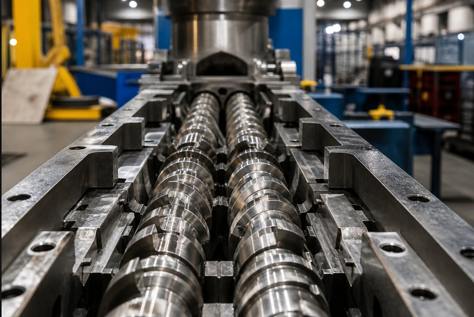
A twin screw extruder for compounding is a modular processing machine in which two intermeshing screws rotate inside a heated, segmented barrel to melt, mix, and homogenize polymers with additives, fillers, pigments, or reinforcements — producing a uniform compound that can be pelletized for downstream molding or forming operations.
That definition matters because it separates compounding from general extrusion. In profile or sheet extrusion, the extruder's job is to melt a single resin and push it through a die to create a shape. In compounding, the twin screw extruder functions more like a continuous chemical reactor: it must disperse carbon black at the nanoscale, distribute glass fibers without breaking them, or blend two immiscible polymers into a stable alloy — all within a residence time measured in seconds.
The fully intermeshing design is central to this capability. As the two screws rotate, they create a self-wiping action that continuously scrapes material from barrel walls and screw surfaces. This prevents stagnation, eliminates dead zones where thermal degradation would otherwise occur, and ensures every particle of material receives a consistent shear and thermal history. The result is the kind of uniform dispersion and distribution that compounding demands.
A twin-screw extruder also offers something no single screw machine can match: a truly modular architecture. Screw elements — conveying flights, kneading blocks, mixing elements, reverse-flight sections — can be rearranged along the shaft to create a custom processing profile for each compound. Barrel segments can be added, removed, or reconfigured with independent temperature zones, side-feed ports, and vacuum vents. This modularity is what allows a single machine to compound glass-filled nylon on Monday and color masterbatch on Wednesday.
Why Compounders Choose Twin Screw Over Single Screw
Single screw extruders are simpler, less expensive, and perfectly adequate for melting and conveying a single polymer. But compounding asks the machine to do far more — and here, twin screw extruders hold decisive advantages:
- Superior distributive and dispersive mixing: The intermeshing screws generate both high-shear dispersive forces (breaking agglomerates apart) and efficient distributive flow (spreading components evenly throughout the matrix). Single screw machines rely primarily on drag flow along one channel, which limits mixing intensity.
- Modular screw and barrel design: Segmented screw elements and barrel sections can be reconfigured to match each formulation — from gentle blending of heat-sensitive additives to aggressive dispersion of nano-fillers. Single screw designs are essentially fixed geometries.
- Independent throughput and speed control: Twin screw compounding typically operates in starve-fed mode, meaning feed rate and screw speed can be adjusted independently. This decoupling gives engineers direct control over specific energy input and residence time — variables that are locked together on a flood-fed single screw machine.
- Broad material flexibility: Whether the formulation calls for high-viscosity engineering resins, low-bulk-density powders, or 80% mineral filler loading, twin screw extruders handle the range. Their positive conveying action and multiple feed points accommodate materials that would simply not move through a single screw.
- Self-wiping capability: The figure-eight flow pattern created by co-rotating intermeshing screws continuously cleans the screw and barrel surfaces. This minimizes material residence, reduces degradation risk, and shortens changeover times between products — a practical benefit that compounds directly into production efficiency.
These aren't theoretical advantages. They explain why the fully intermeshing co-rotating twin-screw extruder has become the mainstream platform for polymer compounding worldwide.
Yet knowing why twin screw technology dominates is only the starting point. The real compounding expertise lies in understanding how to configure these machines — beginning with a choice that shapes every process decision downstream: co-rotating or counter-rotating screw arrangement.
Co-Rotating vs Counter-Rotating Twin Screw Extruders Compared
This single decision — co-rotating or counter-rotating — determines the shear field, mixing mechanism, and processing window of every compound you'll ever run. Surprisingly, most equipment literature treats it as a bullet-point comparison. Compounders deserve better, because choosing the wrong configuration means fighting the physics of your formulation from day one.
Both configurations use twin screws inside a heated barrel, and both are available in intermeshing and non-intermeshing variants. Intermeshing designs, where the flight of one screw extends into the channel of the other, dominate compounding because they provide positive material conveyance and controlled shear. Non-intermeshing arrangements, with screws operating more independently, find niche use where gentler material exchange is preferred. Within the intermeshing category, the rotation direction changes everything about how material flows, melts, and mixes.
How Co-Rotating Twin Screw Extruders Work
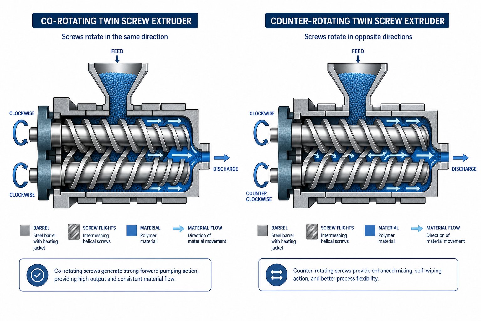
In a co rotating twin screw extruder, both screws turn in the same direction — typically with a fully intermeshing geometry. Imagine the two screws as interlocking gears that hand material off to each other in a continuous figure-eight (or infinity-shaped) flow pattern. At the intermeshing zone, one screw's flight wipes the other screw's root, and vice versa. This self-wiping action is what makes the co-rotating design so powerful for compounding.
You'll notice several practical consequences of this geometry. Dead zones virtually disappear because the self-wiping motion continuously scrapes material from every surface. The residence time distribution stays narrow, which is critical when processing thermally sensitive polymers or running reactive extrusion where even a few extra seconds at temperature can cause degradation. Material undergoes intense shear both between the twin screws and between each screw and the barrel wall, while kneading blocks add elongational flow components that break apart filler agglomerates and refine polymer blend morphology.
The modular screw design further extends this advantage. A co rotating twin screw extruder allows engineers to freely combine conveying elements, kneading blocks at various stagger angles, and mixing elements — placing energy input exactly where the formulation needs it. This flexibility is why co-rotating machines handle the broadest range of compounding applications: mineral-filled compounds, polymer alloys like PC/ABS, color masterbatch, reactive extrusion, and even nanocomposites incorporating carbon nanotubes or cellulose nanofibers.
When Counter-Rotating Configuration Is the Better Choice
Counter-rotating twin screw extruders spin their screws in opposite directions. Rather than wiping each other clean, the screws draw material into the intermeshing region and compress it forward — producing a calendering effect similar to the nip between two calender rolls. Material undergoes compressive and elongational deformation rather than the high-shear dispersive mixing characteristic of co-rotating machines.
This gentler processing environment exists by design, not by limitation. Rigid PVC, for example, has a low thermal decomposition temperature and poor melt flow — a combination that punishes high-shear processing. A counter-rotating double screw extruder holds the extrusion temperature low through high-fill, low-speed operation, enabling stable production of PVC pipes, sheets, and profiles without triggering degradation.
Counter-rotating machines also come in a conical twin screw extruder configuration, where the screws taper from a larger diameter at the feed end to a smaller diameter at the discharge. This geometric compression enhances melting and provides high torque transmission in a compact footprint — making the conical twin screw extruder a popular choice for medium-capacity PVC processing lines. Parallel counter-rotating designs are also available, though less common in general compounding.
Beyond PVC, counter-rotating configurations suit any application where shear-induced heat generation must be minimized: certain pharmaceutical formulations, shear-sensitive biopolymers, and specialty compounds where maintaining molecular weight is paramount.
Structured Comparison for Compounding Engineers
When evaluating co rotating and counter rotating twin screw extruder options side by side, a structured technical comparison cuts through the marketing noise. The table below summarizes the key differences that matter on the plant floor:
| Feature | Co-Rotating | Counter-Rotating |
|---|---|---|
| Rotation Direction | Both screws same direction | Screws in opposite directions |
| Self-Wiping Ability | Fully self-wiping (intermeshing) | Limited; not inherently self-wiping |
| Shear Intensity | High; adjustable via screw element selection | Lower; relies on calendering and compressive forces |
| Dominant Mixing Type | Strong dispersive and distributive mixing | Primarily compressive and elongational mixing |
| Throughput Capacity | Higher; well-suited for large-scale production | Moderate; optimized for high-fill, low-speed operation |
| Typical L/D Ratio | 32:1 to 52:1 (or higher) | 16:1 to 28:1 (especially conical designs) |
| Primary Compounding Applications | Filled compounds, masterbatch, polymer blends, reactive extrusion, nanocomposites | Rigid PVC profiles/pipes, shear-sensitive polymers, select specialty formulations |
| Scale-Up Flexibility | Excellent; modular design scales from lab to production | More application-specific; scaling follows established PVC/specialty protocols |
A few patterns stand out. Co-rotating machines dominate general-purpose compounding because they offer the widest processing window and greatest screw design flexibility. Counter-rotating machines carve out a strong position in PVC and applications where thermal sensitivity overrides the need for intensive mixing. In practice, many compounding operations will only ever need a co-rotating platform — but recognizing the scenarios where counter-rotating configurations genuinely outperform prevents costly mismatches between machine and material.
Choosing the right rotation direction sets the foundation, yet it's only the first layer of configuration. The real fine-tuning happens inside the barrel — zone by zone, element by element — where the screw profile transforms raw ingredients into a finished compound.
Barrel Zones and Screw Element Design Explained
Every compound you produce is shaped by what happens inside the barrel — not in broad strokes, but zone by zone, element by element. Supplier spec sheets list barrel length, L/D ratio, and number of heating zones, yet they rarely explain why each zone exists or how the screw elements inside it interact with temperature to determine compound quality. That's the gap this section fills.
Think of a twin screw extruder machine as a sequence of specialized processing stages arranged in series along the barrel. Each stage has a distinct job, uses specific screw element types, and requires its own temperature strategy. The modular screw and barrel architecture — the defining advantage of twin screw extrusion — makes this possible. Screw elements slide onto splined shafts and can be rearranged without modifying the machine frame. Barrel segments bolt together with independent heating and cooling circuits. This modularity lets compounders redesign the processing profile for every new formulation without buying a new machine.
Five Functional Zones of a Compounding Barrel
A typical compounding screw profile divides into five functional zones, each building on the one before it. Here's how material progresses through the barrel from feed throat to die face:
- Solids Conveying and Feeding Zone — Raw polymer pellets, powders, and granular additives enter through the feed throat, typically via a gravimetric or volumetric feeder. The screw elements here are high-lead (large pitch) conveying elements designed to grab low-bulk-density solids and move them forward quickly. Deep channels and wide flights maximize free volume, preventing bridging at the inlet. Barrel temperatures in this zone are kept relatively low — often with cooling water circulating through the feed barrel segment — to avoid premature melting that would form a plug and block incoming material. In starve-fed operation, the fill level in this zone remains low, and air escapes rearward through the feed opening.
- Melting and Plasticizing Zone — As the conveying elements push material downstream, barrel temperatures begin to ramp upward. The screw profile transitions from conveying flights into the first set of kneading blocks, which generate shear heat through mechanical deformation. This combination of conducted heat from the barrel wall and viscous dissipation from the kneading elements converts solid pellets into a continuous melt. The barrel temperature profile through this zone typically follows an ascending gradient, rising toward the target processing temperature of the polymer. Kneading blocks with moderate stagger angles — often 45° or 60° — provide enough shear to complete melting without generating excessive melt temperature.
- Intensive Mixing and Kneading Zone — This is the heart of the compounding process. After the polymer is fully melted, the screw profile shifts to more aggressive mixing elements — kneading blocks with larger stagger angles (60° or 90°), toothed mixing elements (ZME/TME), or specialized distributive mixing designs. The goal here is twofold: dispersive mixing to break apart filler agglomerates and reduce particle size, and distributive mixing to spread all components uniformly throughout the polymer matrix. Research at Paderborn University using 3D CFD simulations with particle tracking demonstrated that screw element geometry and rotation speed are the two most significant factors influencing both dispersive and distributive mixing quality in this zone. Barrel temperatures here are typically held steady at or slightly below the target melt temperature — the intent is to let mechanical energy from screw extrusion do the mixing work while the barrel provides just enough thermal stability to maintain consistent viscosity.
- Venting and Devolatilization Zone — After intensive mixing, the melt passes through a pressure-release section where volatile compounds, trapped air, and moisture are extracted. The screw elements return to conveying flights — typically high-lead elements that reduce fill level and expose fresh melt surface for volatiles to escape. Venting can be atmospheric (open barrel port) or vacuum-assisted (sealed port connected to a vacuum pump), depending on the volatile content of the formulation. A critical design detail here is the melt seal that must exist upstream of the vent port to prevent melt from flowing backward and out through the opening. This seal is created by reverse-flight elements or reverse kneading blocks positioned just before the vent zone. Barrel temperature in this zone is generally maintained at a level that keeps the melt fluid enough for effective devolatilization without promoting thermal degradation.
- Pressure Build-Up and Discharge Zone — The final barrel section must generate enough pressure to push the homogenized compound through a die plate or screen pack. Low-lead (small pitch) conveying elements are used here because their shorter flight pitch creates higher pressurization per unit length. The barrel temperature often decreases slightly compared to the mixing zone — reducing melt temperature improves melt strength at the die and helps prevent stranding issues during pelletizing. As documented in twin-screw compounding process literature, this zone shapes the melt into strands that are then cooled and chopped into pellets in downstream equipment.
Each of these zones occupies a different proportion of the total barrel length depending on the formulation. A highly filled mineral compound might dedicate more barrel length to mixing, while a moisture-sensitive recycled polymer might require an extended venting section with multiple vacuum ports.
How Screw Element Selection Shapes Compound Quality
Within these five zones, the specific screw elements you choose — and how you arrange them — are what separate an acceptable compound from an excellent one. Two element types deserve closer attention because they do the heaviest lifting in any compounding screw profile: kneading blocks and reverse-flight elements.
Kneading blocks are stacks of elliptical discs mounted on the screw shaft at offset angles to one another. The stagger angle — the angular offset between adjacent discs — is the single most important variable controlling mixing intensity:
- 30° stagger angle: Provides mild, forward-conveying mixing. Material flows relatively easily through the kneading section with moderate shear. Best suited for gentle blending where the polymer or additive is thermally sensitive and excessive energy input would cause degradation.
- 45° stagger angle: A balanced middle ground. Offers good dispersive and distributive mixing with moderate forward conveyance. Often used in melting zones and for general-purpose compounding of mineral fillers or pigments.
- 60° stagger angle: Increases shear intensity and residence time within the kneading section. Material moves forward more slowly, spending longer under high-shear conditions. Effective for breaking apart tightly bonded filler agglomerates in applications like calcium carbonate or talc-filled compounds.
- 90° stagger angle (neutral kneading blocks): Generates maximum shear with zero forward conveying action. Material must be pushed through entirely by upstream elements, creating the highest fill level and longest local residence time. CFD analysis confirms that 90° kneading blocks achieve better distributive mixing than 45° blocks under identical process conditions — the KB24 with 90° stagger consistently outperformed the KB45 across multiple rotation speeds and polymer viscosities. However, this comes at a cost: higher melt temperature and greater specific energy input.
Disc width within kneading blocks adds another layer of control. For the same total element length, narrower discs mean more discs per block and more frequent material exchange at the disc tips, boosting dispersion. Wider discs provide longer residence time per disc passage with gentler mixing — useful for shear-sensitive formulations.
Reverse-flight elements serve a completely different purpose. These left-handed conveying elements oppose the normal downstream flow direction, creating a localized region of high pressure and full barrel fill. Why does this matter? Because effective venting demands a gas-tight melt seal upstream of every vent port. Without it, melt flows backward through the vent opening — a condition called vent flooding that contaminates the vacuum system and halts production. Reverse elements (or reverse kneading blocks) positioned just before the venting zone create that seal by forcing material to build pressure and fill the barrel cross-section completely, blocking any upstream gas migration path.
Beyond venting, reverse elements also increase residence time in mixing zones. Placing a short reverse-flight section downstream of a kneading block forces material to accumulate in the mixing region longer, intensifying both dispersive and distributive mixing. The trade-off is higher melt temperature and increased torque load on the drive — a balance that experienced screw extruder engineers learn to manage by adjusting reverse element length, lead pitch, and upstream kneading block intensity together as a system.
The interplay between these elements — conveying, kneading, mixing, and reverse — is what gives the extruder twin screw design its extraordinary versatility. But even a perfectly configured screw profile can produce a mediocre compound if the process parameters running through those zones aren't properly controlled. The next critical layer involves the variables that determine exactly how much energy, heat, and time your material experiences at each stage.
Critical Process Parameters That Control Compound Quality
A perfectly designed screw profile sitting inside a precisely configured barrel still won't guarantee a good compound. Why? Because the dynamic variables — screw speed, feed rate, temperature setpoints, torque — are what breathe life into the hardware. These process parameters interact with each other in ways that supplier manuals rarely explain as a unified system. Change one, and you inevitably shift others. Understanding these interactions is what separates a compounder who troubleshoots by instinct from one who controls quality by design.
Every twin screw extrusion process boils down to a three-way balancing act: screw speed, throughput, and compound quality. Push throughput too high without compensating screw speed, and mixing suffers. Crank up screw speed to improve dispersion, and melt temperature climbs beyond the safe window for heat-sensitive additives. Reduce both to play it safe, and your production economics fall apart. The key is understanding how each parameter influences the others — and which ones to monitor in real time to keep the process inside its operating window.
Screw Speed, Specific Energy, and Their Impact on Mixing
Screw speed is the most intuitive variable a compounder reaches for when mixing quality falls short. Higher RPM means greater shear rate in the kneading zones, which improves dispersive mixing — breaking apart filler agglomerates, refining droplet size in polymer blends, and accelerating melting. It sounds straightforward, but there's a catch that every experienced operator knows: increasing screw speed also increases melt temperature.
This happens because higher shear rates generate more viscous dissipation — essentially, the mechanical energy from the motor converts into heat within the polymer melt. In a compounding extruder, particularly in zones loaded with kneading blocks, this effect can be substantial. Research on twin-screw compounding parameters confirms that screw speed and feed rate have the greatest impact on melt temperature, with higher screw speeds delivering more mechanical energy input in the mixing zones and directly raising the thermal load on the compound.
For heat-sensitive formulations — flame retardant compounds, certain biopolymers, PVC-based materials — this creates a real dilemma. You need enough screw speed to achieve adequate dispersion, but too much pushes the melt into a degradation window. The solution lies in a metric that captures both sides of this trade-off: specific energy input (SEI), measured in kWh/kg or kJ/kg.
Specific energy represents the total mechanical energy delivered to each kilogram of compound. It's calculated from motor power draw divided by mass throughput. As a laboratory-scale example, a twin-screw compounding trial run at 1 kg/h throughput and 200 rpm screw speed yielded a specific energy of 559 kJ/kg. That number becomes the fingerprint of the process — and maintaining it during scale-up or recipe adjustments is one of the most reliable ways to preserve compound quality.
When you increase screw speed at constant throughput, SEI rises because the motor works harder on the same amount of material. When you increase throughput at constant screw speed, SEI drops because the same energy is spread across more material. This inverse relationship is the foundation of the screw speed-throughput-quality triangle. Finding the sweet spot requires iterative adjustment — not a single formula — because the optimal SEI depends on the specific polymer system, filler type, and target dispersion level.
Temperature Profiles and Feed Rate Optimization
Barrel temperature zones interact with screw speed to determine the thermal environment your compound experiences at every stage. Imagine the barrel as a sequence of independently controlled ovens wrapped around the screw, each one tunable to support the processing function happening inside it.
A typical compounding twin screw extruder uses an ascending temperature profile through the feeding and melting zones — starting relatively cool at the feed throat (to prevent bridging and premature melting) and ramping upward through the plasticizing section to reach the polymer's processing temperature. Through the intensive mixing zones, barrel temperatures are typically held steady or drop slightly. This might seem counterintuitive, but there's a practical reason: the kneading blocks are already generating significant shear heat, so the barrel's job shifts from adding energy to stabilizing or even removing excess heat to keep the melt temperature within specification.
In the discharge zone, a slight temperature reduction often improves melt strength at the die, producing more stable strands for pelletizing. This overall strategy — ascending through melting, plateau through mixing, slightly descending at discharge — provides a useful starting framework, though every formulation will demand its own fine-tuning.
Equally important is feed rate strategy. In twin screw compounding, starve-fed operation is the standard — and understanding why gives you a critical advantage. In a starve-fed extruder system, the gravimetric feeder meters material into the barrel at a controlled rate that is lower than the screw's maximum conveying capacity. This means the barrel is only partially filled in the conveying zones, and the feed rate is independent of screw speed.
Why does this matter? Because decoupling throughput from screw speed gives you two independent control levers instead of one. You can raise screw speed to increase shear and dispersive mixing without automatically increasing throughput — or you can increase throughput without changing the shear environment. In contrast, a flood-fed single screw extruder locks these variables together: higher screw speed means higher output, period. Starve feeding is what makes the twin screw platform so flexible for compounding, allowing engineers to independently dial in the specific energy that each formulation demands.
Monitoring Torque and Residence Time
Knowing which parameters to watch in real time is just as important as understanding the theory behind them. A compounding line generates a constant stream of data, but five variables tell you the most about process health and compound quality at any given moment:
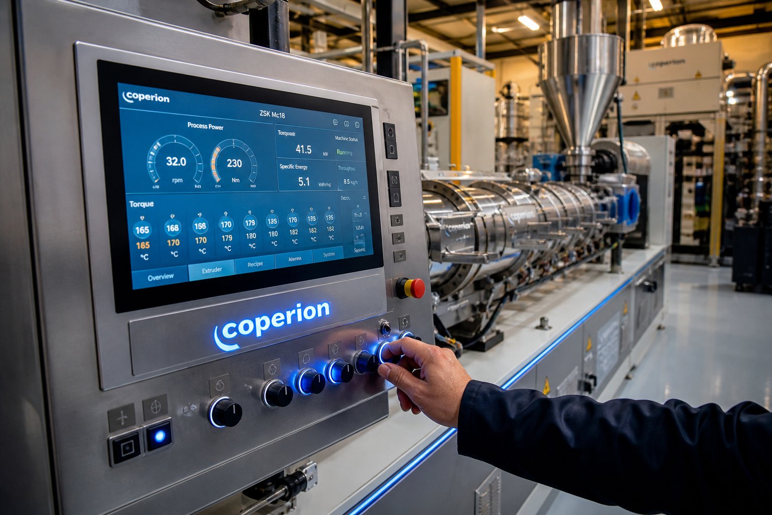
- Screw torque percentage: Expressed as a percentage of the motor's maximum rated torque, this is your primary indicator of how hard the screws are working. Rising torque at constant conditions signals increasing melt viscosity — possibly from undissolved polymer, filler loading creep, or insufficient barrel temperature. A sudden torque spike can indicate metal-to-metal contact from a broken screw element or foreign contamination. Most operators target a steady-state torque range well below the motor's maximum (often in the 40-70% range, depending on machine and formulation) to maintain a safety margin.
- Melt temperature: Measured at the die or barrel exit, melt temperature reflects the combined effect of barrel heat input and shear-generated energy. It's the final check on whether your screw speed and temperature profile are in harmony. Process data from twin-screw compounding studies confirms that screw speed and feed rate exert the greatest influence on this variable. If melt temperature drifts upward during a run, the likely culprits are barrel wear (increasing shear in wider clearances), feeder inconsistency, or gradual fouling of cooling channels.
- Die pressure: Pressure measured at the die plate reflects downstream resistance and melt viscosity. Stable die pressure indicates consistent melt quality and flow. Fluctuations suggest surging — often traceable to uneven feeding, incomplete melting, or vent flooding upstream.
- Motor load (power draw): The instantaneous power consumed by the drive motor, usually displayed in kilowatts or as a percentage of rated capacity. This feeds directly into the specific energy calculation (power divided by throughput). Monitoring motor load trends over a production run reveals whether the extruder system is operating in a steady state or drifting — an early warning system for process deviations.
- Specific energy consumption (SEI): Calculated in real time from motor power and feed rate, SEI is arguably the single most important quality indicator in compounding. Holding SEI constant across batches, shifts, and even scale-up stages is the closest thing to a universal rule for maintaining compound consistency. If your control system doesn't calculate it automatically, it's worth setting up a manual log — the discipline of tracking this number pays dividends in troubleshooting and quality assurance.
One additional parameter deserves attention even though it's harder to measure: residence time distribution (RTD). RTD describes not just how long material stays in the barrel on average, but how wide the spread of residence times is across all the material passing through. A narrow distribution means every particle gets a similar thermal and shear history — which translates to uniform compound properties. A wide distribution means some material is undertreated while other material is overprocessed, leading to inconsistency in the pellet bag.
Throughput has the most dramatic effect on residence time. Studies on twin-screw compounding show that increasing throughput reduces both the average residence time and the width of the residence time distribution. Screw speed, perhaps surprisingly, has a relatively small direct influence on residence time — its primary effect is on shear rate and energy input rather than material transit speed. However, backward-mixing elements like reverse-flight sections and 90-degree kneading blocks significantly increase local residence time and broaden the overall distribution, which is why their placement and length must be carefully balanced against formulation sensitivity.
Taken together, these parameters form an interconnected web. Adjusting any one of them ripples through the others. The compounder's real skill lies not in optimizing a single variable in isolation but in managing the entire parameter set as a system — always keeping one eye on specific energy as the unifying metric. With these process fundamentals in place, the question shifts from how to control the process to what you're processing — and the answer varies dramatically depending on whether your compound is a glass-filled polyamide, a color masterbatch, or a recycled resin full of contaminants.
Compounding Applications Across Different Material Systems
Glass-filled nylon, color masterbatch, and recycled HDPE all run on the same twin screw compounding extruder — yet each one demands a fundamentally different screw profile, temperature strategy, and feeding approach. The process parameters discussed earlier aren't abstract variables; they change meaning depending on what's actually inside the barrel. A screw speed that delivers perfect carbon black dispersion in a masterbatch application might shatter every glass fiber in a reinforced polyamide compound. This is where the real expertise lives: matching machine configuration to material system.
What follows is a material-by-material breakdown covering the major compound families, each with the specific screw configuration and process considerations that separate good results from great ones.
Filled and Fiber-Reinforced Compound Processing
Mineral-filled compounds — calcium carbonate, talc, glass beads, barium sulfate — represent the highest-volume category of twin screw extruder plastic compounding. The key challenge is achieving uniform dispersion of high filler loadings (sometimes exceeding 70-80% by weight) without excessive barrel and screw wear. For these formulations, the screw profile typically concentrates aggressive kneading blocks with 60° or 90° stagger angles in the mixing zone to break apart filler agglomerates, while conveying sections are kept efficient to maintain throughput.
When filler content exceeds roughly 40-50%, the main feed port simply can't ingest all the material at once. This is where side feeding becomes essential. A downstream side feeder introduces part or all of the filler after the polymer has already melted, preventing feed-throat clogging, reducing torque spikes, and improving filler wetting by presenting dry particles to a fully molten matrix rather than a partly solid polymer bed.
Fiber-reinforced compounds — glass fiber and carbon fiber systems — introduce an entirely different constraint: preserving fiber length. Longer fibers deliver better mechanical properties (tensile strength, impact resistance, heat deflection temperature), but every kneading block and tight clearance in the barrel shortens them. Research at the Universities of Kassel and Paderborn demonstrated this clearly: when compounding glass fiber-reinforced polypropylene on co-rotating twin screw extruders, a screw configuration containing kneading blocks and mixing elements (SC1) consistently produced shorter fiber lengths than a configuration using only conveying elements after the fiber feeding point (SC2). The effect intensified as fiber loading increased from 20 to 40 wt.%, with higher fiber content driving greater breakage under identical process conditions.
The practical solution is downstream fiber feeding. Rather than introducing fibers through the main feed hopper — where they would endure the full melting and kneading zones — fibers enter the barrel via a side feeder positioned after the polymer has already been melted and mixed. This minimizes the number of high-shear elements the fibers encounter. Screw configurations downstream of the fiber feed point should favor gentle conveying elements and avoid aggressive kneading blocks whenever possible. Even the choice of extruder matters: the same Kassel/Paderborn study found that identical screw configurations on different twin screw extruders produced different fiber length distributions — likely due to manufacturer-specific tolerances in barrel-to-screw clearances. This underscores that fiber compounding results depend not just on the screw profile but on the specific machine geometry.
Carbon fiber compounds follow similar principles but with heightened sensitivity. Carbon fibers are more brittle than glass fibers and break more readily under shear. Reducing screw speed, minimizing kneading block intensity downstream of the fiber feed, and keeping throughput high relative to screw RPM (lowering specific energy) all help preserve fiber length. For any polymer extruder handling fiber-reinforced formulations, the mantra is simple: add fibers late, process them gently, and validate fiber length in the finished pellet — not just in the raw material data sheet.
Polymer Blends, Masterbatch, and Specialty Compounds
Beyond filled and reinforced systems, a plastic twin screw extruder handles an enormous range of specialty compounds. Each poses its own unique challenge, and the screw configuration focus shifts accordingly. The table below summarizes the critical considerations for four major specialty compound types:
| Compound Type | Key Challenge | Screw Configuration Focus | Critical Parameter |
|---|---|---|---|
| Polymer Blends (e.g., PC/ABS, PA/PP) | Achieving stable blend morphology between immiscible polymers; preventing delamination | Intensive dispersive mixing zones with 60-90° kneading blocks to refine droplet size; compatibilizer feeding upstream of primary mixing zone | Specific energy input — must be high enough to develop fine, uniform phase morphology without degrading either polymer |
| Color Masterbatch | Breaking down pigment agglomerates (especially carbon black and organic pigments) to achieve streak-free, uniform dispersion at high pigment loading | Multiple high-shear kneading zones; narrow kneading disc widths for frequent material exchange; self-wiping geometry critical for fast color changes | Residence time — must be short enough to prevent thermal degradation of organic pigments while long enough for complete dispersion |
| Flame Retardant Compounds | Heat-sensitive additives (halogenated or phosphorus-based FR agents) degrade or release corrosive gases at elevated temperatures | Moderate-shear mixing elements; avoid 90° neutral kneading blocks that generate excessive local temperatures; extended conveying sections for heat dissipation | Melt temperature — must stay below additive decomposition threshold; barrel cooling capacity becomes the limiting factor |
| Recycled Polymer Compounds | Inconsistent feedstock quality; contamination from mixed polymer streams, labels, adhesives; high moisture and volatile content | Extended devolatilization section with multiple vacuum vents; screen changers at discharge; robust melting zone to handle variable melt viscosity | Vacuum level and vent port positioning — effective devolatilization is the single biggest quality lever for recycled compound clarity, odor, and mechanical performance |
A few points deserve emphasis. Polymer blends like PC/ABS or PA/PP are almost always immiscible — they won't mix into a single phase on their own. A compatibilizer (typically a maleic anhydride-grafted polymer) must be introduced to reduce interfacial tension and stabilize the blend morphology. Without it, the blend separates under stress and fails in application. The compatibilizer should be fed alongside the base resins and processed through the most intensive mixing zones so it can migrate to the interface between the two polymer phases.
Color masterbatch production, meanwhile, demands the extruder for polymer and pigment integration to operate with exceptional self-wiping performance. As industry practitioners emphasize, carbon black is one of the most difficult materials to disperse due to its small particle size, high surface energy, and tendency to form tightly bonded agglomerates that resist breakup. The screw plastic extruder configuration for black masterbatch typically features multiple sequential kneading zones with narrow disc widths, creating repeated cycles of high-shear exposure that progressively reduce agglomerate size. Between production runs, the co-rotating self-wiping action minimizes pigment residue and cross-contamination — a critical advantage in operations that frequently change colors.
For flame retardant compounds, the challenge flips entirely. Instead of maximizing shear, you're managing thermal sensitivity. Many halogenated flame retardants begin decomposing above 200-220°C, releasing corrosive hydrogen halide gases that attack screw and barrel surfaces. The twin screw plastic extruder handling these formulations needs corrosion-resistant barrel liners, careful temperature zoning with aggressive barrel cooling to counter shear-generated heat, and gentle mixing elements that achieve adequate additive distribution without the temperature excursions that aggressive kneading blocks would produce.
Recycled polymer compounding — increasingly important under circular economy mandates — is perhaps the most demanding application because the feedstock itself is unpredictable. Post-consumer recycled polyethylene or polypropylene can arrive with moisture content, residual inks, adhesive residues, mixed polymer contamination, and wildly variable melt flow index. The screw profile for recycling operations prioritizes extended devolatilization with multiple vent ports (often two or three vacuum vents in series) to strip out volatiles responsible for odor and discoloration. A polyester extruder line processing recycled PET faces an additional challenge: hydrolytic degradation. PET must be dried to extremely low moisture levels before processing, and the devolatilization section must be aggressive enough to remove any residual moisture that survived pre-drying.
Emerging Compounding Applications
Two rapidly growing application areas are expanding the role of twin screw extruders beyond traditional plastics compounding.
Bio-based polymer compounding — processing PLA, PHA, PBS, and starch-based blends — brings unique challenges because many biopolymers have narrow processing windows, are moisture-sensitive, and degrade quickly under excessive shear. Market analysis from Polaris Market Research identifies bio-based polymers as a key growth driver for the twin screw extruders market, which was valued at USD 2.91 billion in 2024 and is projected to grow at a CAGR of 5.06% through 2034. Compounding bio-based resins with natural fiber reinforcements (flax, hemp, cellulose) or mineral fillers for rigidity requires screw profiles that balance adequate mixing with thermal restraint — often favoring lower screw speeds and shorter barrel lengths than conventional petrochemical polymer compounding.
Battery material compounding is an even newer frontier. Lithium-ion battery electrodes require uniform dispersion of active materials, conductive additives (carbon black, carbon nanotubes), and binders in solvent or dry-process systems. Twin screw extruders are increasingly being evaluated for continuous dry electrode manufacturing, replacing batch mixing processes that struggle with consistency at scale. The demands are extreme — particle-level dispersion uniformity, precise residence time control, and contamination-free processing — but they align perfectly with the core capabilities that make twin screw technology dominant in conventional polymer compounding.
Each of these material systems generates its own set of volatiles, moisture, and byproducts that must be removed during processing — which brings the discussion to two interconnected topics that are often mentioned in passing but rarely explained in the depth compounders actually need: venting configurations and downstream pelletizing equipment.
Venting, Devolatilization, and Downstream Equipment Integration
Moisture, trapped air, residual monomers, and volatile additives don't just disappear because you melted and mixed everything properly. If they stay in the compound, they show up later as bubbles in injection-molded parts, surface defects in extruded profiles, or degraded mechanical properties that trigger customer complaints. Removing these volatiles — devolatilization — is a mass-transfer process that depends on exposing fresh melt surface to a low-pressure environment. And what happens after the melt exits the die — pelletizing, cooling, classification — determines whether your carefully compounded material arrives at the customer in a form they can actually use.
Most supplier literature treats venting as a single bullet point and pelletizing as an afterthought. In practice, these two subsystems are where compounding lines most often underperform — and where targeted improvements deliver the fastest payback.
Atmospheric and Vacuum Venting Configurations
Every venting zone on a twin-screw extruder machine shares the same basic architecture: a partially filled section of the screw isolated between two fully filled regions. The filled regions act as melt seals — gas-tight barriers that prevent air or vacuum from leaking into adjacent barrel zones. As devolatilization specialist Rob Jerman explains, these seals are typically created by non-pumping elements such as reverse-flight conveying elements, neutral kneading blocks, or restrictive blisters positioned upstream and downstream of the vent port.
The upstream seal prevents vacuum from pulling backward through the feed section. The downstream seal — often established by the die itself or by a second set of reverse elements — prevents vacuum from drawing forward through the discharge. Between these two seals, high-lead conveying elements reduce fill level, exposing a thin layer of melt with maximum surface area for volatiles to escape through the open vent port above.
Atmospheric vents are the simpler configuration. An open port in the barrel allows trapped air and surface moisture to escape at ambient pressure. They're commonly placed in the transition between melting and mixing zones, where air entrained during solids conveying needs an exit path before the melt enters intensive kneading sections. Atmospheric vents are effective for removing free moisture and air but lack the driving force to extract dissolved volatiles or low-concentration contaminants.
Vacuum vents apply negative pressure — typically 50 to 200 mbar absolute, though deeper vacuum is used for demanding applications — to pull dissolved volatiles, residual monomers, and moisture from the melt. The vacuum dramatically lowers the partial pressure of the volatile component, increasing the thermodynamic driving force for mass transfer out of the polymer. Each vacuum vent can reduce volatile concentration by roughly an order of magnitude — a practical rule of thumb that means a triple-vented machine can bring a 50%-solids feed down to less than 0.1% residuals.
Vacuum level must be matched to volatile content and polymer sensitivity. Pulling excessively deep vacuum on a polymer prone to depolymerization (certain acrylics and styrenics, for example) can actually increase residual volatiles because the polymer unzips faster than the devolatilization zone can strip the byproducts. There's a practical ceiling beyond which more vacuum does more harm than good.
The most common operational headache with venting is vent flooding — melt backing up into the vent port and eventually clogging the vacuum piping. This happens when the downstream melt seal is too restrictive, the throughput too high relative to screw speed, or the screw speed too low to maintain short filled lengths behind the seals. As process conditions shift, the filled length behind the downstream seal can creep backward until polymer reaches the vent opening. Jerman notes that for twin-screw extruders, changes in screw speed directly alter seal stability — increasing speed shortens the filled length (making seals more susceptible to failing), while decreasing speed lengthens it (risking backup into the vent). Troubleshooting vent flooding usually involves adjusting the balance between throughput, screw speed, and the restriction level of the downstream seal element.
Downstream Equipment Selection for Pelletizing
The compound exits the die as molten strands or droplets. What converts that melt into usable pellets — and how it's cooled, dried, and classified — has a direct impact on pellet quality, bulk handling properties, and downstream processability. Three pelletizing technologies dominate compounding operations, each with distinct strengths that align with different material systems and production scales.
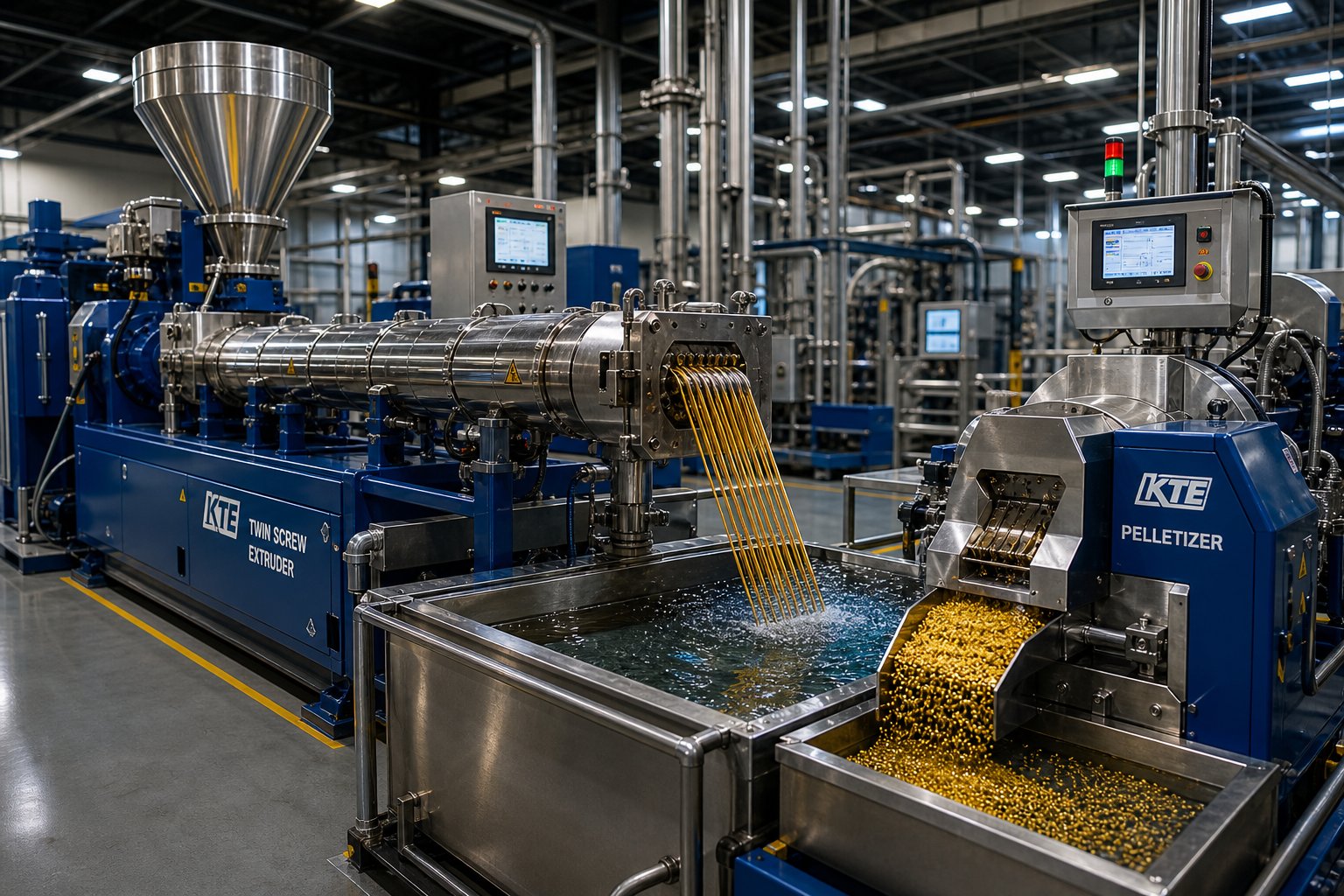
A comprehensive evaluation published by Plastics Technology lays out the practical differences. The strand pelletizer is the simplest and lowest-cost option. Molten strands exit a die, cool in a water bath, dry via an air knife, and are cut into cylindrical pellets by a rotating cutter — functioning essentially as a screw extruder granulator in its most straightforward form. Strand systems excel at flexibility: color changes and material changeovers are fast because the die, water bath, and cutter are easily accessible. The trade-off is labor intensity — threading dozens of strands over guide rolls at each startup requires hands-on operator involvement — and sensitivity to process variations that can cause strand breaks.
The underwater pelletizer (UWP) sits at the opposite end of the complexity and performance spectrum. Molten polymer is cut at the die face while fully submerged in process water, and surface tension forces shape each molten drop into a near-perfect sphere. UWPs offer the highest throughput capacity (up to 70,000 lb/hr), the greatest scope for automation, and the most consistent pellet geometry. They handle virtually any polymer type, from engineering resins to hot-melt adhesives. The downside is higher capital cost and the risk of die freeze-off — when reduced or uneven polymer flow causes the melt to solidify in the die holes.
The water-ring pelletizer (WRP) occupies the middle ground. Like the UWP, it cuts at the die face, but the cutting chamber contains only a ring of water rather than being fully flooded. Pellets are thrown into this water ring, cooled, and transported to a centrifugal dryer. WRPs are compact, moderately automated, and less sensitive to process variations than UWPs. Their limitation is material compatibility — they work best with high-melt-strength polymers like polyolefins and polystyrene and are unsuitable for high-heat or sticky compounds.
| Feature | Strand Pelletizer | Underwater Pelletizer | Water-Ring Pelletizer |
|---|---|---|---|
| Pellet Shape | Cylindrical | Spherical | Rounded, slightly flattened (lens/tablet shape) |
| Throughput Range | Up to ~44,000 lb/hr | Up to ~70,000 lb/hr | Up to ~11,000 lb/hr |
| Best Compound Types | Engineering plastics, filled compounds, masterbatch, recycled resins | Nearly all polymers including hot melts, adhesives, and micropellet applications | High-melt-strength materials: polyolefins, PS; recycling and reclaim |
| Cooling Method | Water bath or water slide followed by air drying | Fully submerged in process water; centrifugal dryer | Water ring in cutting chamber; centrifugal dryer |
| Relative Cost | Lowest | Highest | Moderate |
Choosing among these systems depends on your compound portfolio, throughput requirements, and tolerance for operational complexity. A toll compounder running short batches with frequent material changes will gravitate toward strand pelletizing for its easy access and fast changeovers. A high-volume masterbatch producer or resin manufacturer will typically justify the investment in underwater pelletizing for its automation, pellet consistency, and throughput capacity. A recycler processing polyolefins at moderate volumes may find the water-ring pelletizer hits the sweet spot between cost and performance.
Integrating the Complete Compounding Line
A double screw extruder machine doesn't operate in isolation. The gravimetric feeders upstream, the extruder itself, and the pelletizing and cooling equipment downstream must function as a coordinated system. If any link in this chain is mismatched, the entire line underperforms regardless of how well each individual component is specified.
Imagine what happens when the feeder delivers an inconsistent flow of raw material. Screw torque fluctuates. Melt pressure at the die surges and dips. Strand diameter varies, causing breaks at the pelletizer or oversized pellets that fail downstream classification. The twin-screw extruders themselves might be perfectly configured, but the compound leaving the pelletizer is inconsistent because the input was inconsistent.
The same principle applies in the opposite direction. A pelletizer running at the wrong speed relative to extruder output produces uneven pellet lengths, increases fines generation, and can even back-pressure the die enough to destabilize the venting zones upstream. Cooling water temperature in the pelletizing system must be matched to the compound's crystallization behavior — too cold and brittle polymers fracture during cutting, too warm and soft pellets stick together in the dryer.
Effective integration means three things in practice: synchronized speed control between feeder, extruder, and pelletizer; matched thermal capacity in the cooling system for the target throughput; and a unified monitoring approach that tracks process variables from hopper to pellet bag. When these elements work together, compound quality becomes a function of formulation and process design — not a lottery determined by whichever piece of equipment happens to drift first.
This system-level perspective extends naturally to the hardware that endures the harshest conditions inside the line. The barrel — constantly abraded by mineral fillers, corroded by aggressive additives, and cycled through extreme temperatures — is the wear component that most directly links machine condition to compound quality. When barrel clearances open up from wear, everything discussed in the preceding sections — conveying efficiency, mixing intensity, venting seal integrity — begins to degrade.
Scaling Up Twin Screw Compounding from Lab to Production
You've optimized a formulation on a 26-mm laboratory twin screw extruder — pellet quality looks perfect, specific energy is dialed in, and the vent ports run clean. You transfer the process to a 92-mm production machine using identical screw design, temperature profile, and screw speed. The result? Unmolten pellets discharged through the diverter valve, phase separation, and a waste drum full of unusable material.
That scenario isn't hypothetical. It's exactly what happened in a documented scale-up case study where a masterbatch process was transferred from a 26-mm to a 92-mm twin screw extruder. The initial SME on the production machine dropped to 0.026 kWh/kg — a 69% reduction from the 0.083 kWh/kg achieved at lab scale. The machine simply couldn't deliver enough energy to the material under the same operating conditions that worked perfectly on a smaller platform.
This is the scale-up gap that most equipment literature glosses over. Equations exist. Rules of thumb circulate. But the reality is that translating a compounding process from a lab scale extruder to a production line is one of the highest-risk steps in commercialization — and treating it as a simple proportional exercise virtually guarantees problems.
Scale-Up Principles for Twin Screw Compounding
Successful scale-up rests on maintaining a set of interconnected process parameters proportionally across machine sizes. These are the variables that must be tracked and matched — not the mechanical settings like RPM and barrel setpoints, which almost never transfer directly:
- Specific mechanical energy (SME): The energy input per kilogram of compound (kWh/kg), calculated from motor power draw divided by throughput. This is the single most reliable scale-up reference. In the case study above, maintaining SME near the lab-scale value of 0.083 kWh/kg was what ultimately rescued the process at both pilot (40-mm) and commercial (92-mm) scales — even though achieving that SME required completely different screw designs and temperature profiles at each stage.
- Specific torque (Md/a³): The torque per unit of screw centerline distance cubed. This metric captures the drive system's ability to transfer energy into the material relative to the barrel's volumetric capacity. Matching specific torque across scales ensures the larger machine can deliver enough shear stress to achieve the same degree of melting and mixing.
- Free volume ratio: The open volume available within the barrel for material to occupy. This depends on the screw's outer diameter-to-inner diameter (OD/ID) ratio — a key geometric parameter that must remain consistent between lab and production machines. An OD/ID ratio of 1.55, for example, should be matched across all scales to ensure similar channel depths, shear rates, and conveying characteristics.
- Tip speed: The linear velocity of the screw flight tip, which increases proportionally with diameter at the same RPM. Since tip speed governs peak shear rate, scaling up without reducing RPM exposes the material to shear levels that didn't exist at lab scale. For shear-sensitive compounds, maintaining constant tip speed — rather than constant RPM — prevents thermal damage.
- Residence time distribution (RTD): The spread of time individual material elements spend inside the barrel. RTD tends to broaden at larger scales because flow patterns become less uniform in bigger channels. Wider distributions mean some material is overprocessed while other material is underprocessed — a direct hit to compound consistency.
These parameters are interconnected. Matching SME alone without accounting for tip speed, for instance, might produce the right total energy input but with excessive peak shear that degrades heat-sensitive additives. The discipline lies in monitoring all five together and accepting that trade-offs are inevitable.
From Benchtop to Production Machines
The typical scale-up pathway follows three stages, each serving a distinct purpose — and each introducing risks that the previous stage cannot fully predict.
Stage 1: Benchtop and laboratory extruders (11-27 mm diameter). A benchtop twin screw extruder or small lab twin screw extruder is where formulation development begins. Machines in this range — 16 mm, 18 mm, 20 mm, or 26 mm diameter — handle batch sizes as small as 300 grams to a few kilograms per hour, enabling rapid screening of polymer-filler combinations, additive packages, and screw element arrangements. The goal is to identify the processing window and establish baseline SME. A laboratory scale extruder with the same OD/ID ratio and modular element design as larger production machines provides the best foundation for scale-up data. However, extrusion specialists caution that very small benchtop units with fundamentally different equipment-design attributes don't scale reliably to larger machines — they're useful as screening tools but shouldn't be treated as definitive process development platforms.
Stage 2: Pilot-scale extruders (27-40 mm diameter). This intermediate step is where the first real scale-up surprises appear. In the documented case study, simply replicating the 26-mm process conditions on a 40-mm machine produced significant pressure fluctuations and an SME of only 0.055 kWh/kg — 34% lower than the lab-scale value. The fix required a new screw design with increased melting and mixing sections, a cooler temperature profile, and lower screw speed. After these adjustments, SME recovered to 0.079 kWh/kg (within 5% of the lab target), and the process achieved a 3.64-fold throughput increase over the 26-mm machine — consistent with volumetric scaling predictions.
Stage 3: Production-scale extruders (40-135 mm+ diameter). The jump to full production introduces the most severe thermal challenge. The area-to-volume (A/V) ratio of the barrel decreases dramatically with increasing diameter, meaning the larger machine has proportionally less barrel surface area to conduct heat into — or out of — the melt. Control over heat transfer weakens precisely when the volume of material per screw revolution increases. In the 92-mm case, this reduced A/V ratio, combined with a raw material creating a lubricating effect along the barrel walls, dropped SME to just 0.026 kWh/kg. The solution demanded a complete reevaluation of screw design and feeding configuration — changes that ultimately restored SME to 0.086 kWh/kg and enabled a 12.17-fold throughput increase over the 40-mm machine.
Two scale-up rules govern the theoretical maximum throughput at each stage. If the process is power/volume limited (no heat-transfer constraints), throughput scales with the cube of the diameter ratio. If the process is heat-transfer limited (thermal management governs the rate), throughput scales with the square of the diameter ratio. Geometrically similar extruders — same OD/ID ratio, same L/D ratio — are the prerequisite for either equation to apply. The case study used the cubic relationship because the laboratory extruder showed no heat-transfer limitations, but the problems encountered at the 92-mm scale proved that limitations invisible at small scale can emerge forcefully at production scale.
The overarching lesson is humbling: not all parameters scale linearly, and empirical validation at each stage remains essential. Software tools and scale-up equations provide a starting point — not a destination. As one industry expert puts it, "You still need experienced people who understand the machines to run the physical tests on the line and adjust as needed." The laboratory extruder establishes the target; the pilot machine reveals the first mismatches; the production machine exposes every remaining assumption. Treating each stage as a learning opportunity — rather than a simple multiplication exercise — is what separates successful scale-ups from expensive failures.
Scale-up methodology addresses how the process transfers across machine sizes. But even a perfectly scaled process will drift over time if the hardware degrades — and no component degrades faster or more consequentially than the barrel itself, especially when processing the abrasive and corrosive compound types discussed earlier.
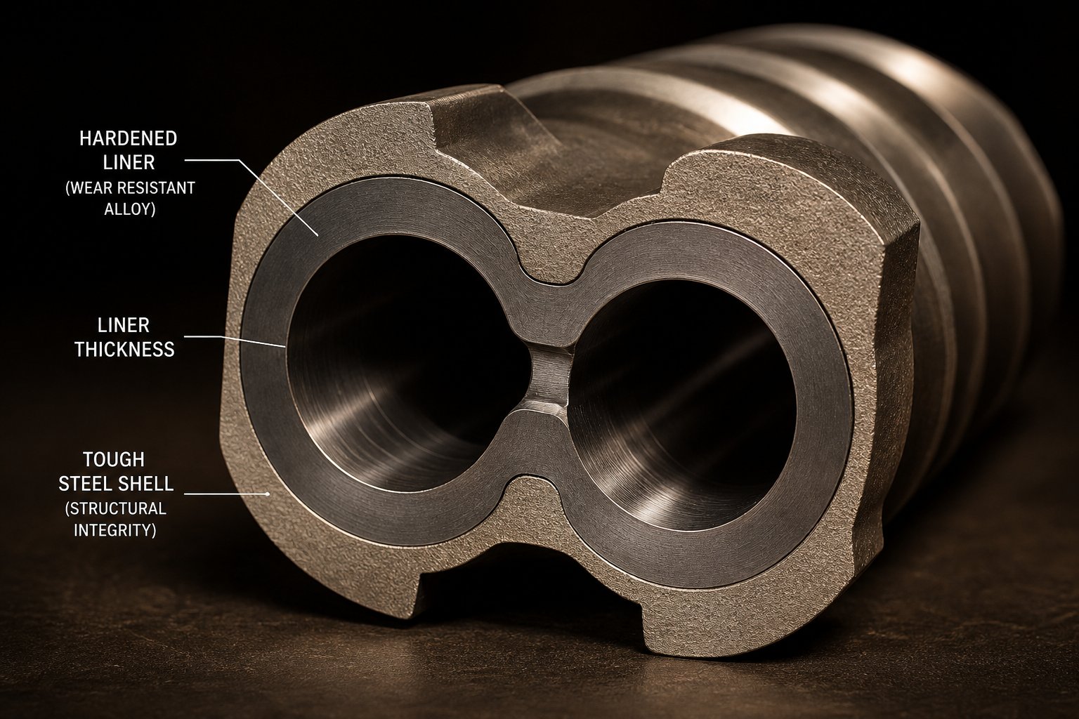
Selecting the Right Twin Screw Barrel for Demanding Compounds
Think about every compound type discussed in the preceding sections — 60% CaCO3-filled polyolefins grinding through the mixing zones, halogenated flame retardants releasing corrosive HCl gas at processing temperatures, glass fibers acting as micro-cutting tools against metal surfaces. All of that punishment lands squarely on the twin screw barrel. It's the component that defines the boundary between the melt and the machine, and when it wears, every upstream process variable you've carefully optimized — conveying efficiency, mixing intensity, vent seal integrity — starts drifting in the wrong direction.
Barrel selection rarely gets the attention it deserves during initial machine specification. Engineers spend weeks configuring screw profiles and dialing in temperature setpoints, then accept whatever barrel metallurgy ships standard with the extruder. That default approach works fine for unfilled commodity polymers. For anything abrasive, corrosive, or high-throughput, it's one of the most expensive shortcuts in compounding.
Why Barrel Wear Undermines Compounding Performance
Imagine what happens inside a barrel extruder as the bore diameter gradually widens from wear. The clearance between screw flight tip and barrel wall increases — and that gap governs everything about how the machine processes material.
In a properly fitted twin screw and barrel assembly, tight clearance forces polymer forward along the screw channel with minimal leakage flow backward over the flight tips. As that clearance opens, documented studies show output rates falling 8% to 15% once clearance widens from the nominal 0.1-0.2% of screw diameter to roughly 0.5 mm or beyond. But output loss is only the beginning. Here's what else degrades:
- Mixing intensity drops. The shear rate between flight tip and barrel wall is inversely proportional to clearance. Wider gaps mean lower shear, which directly weakens dispersive mixing — the mechanism responsible for breaking apart filler agglomerates and refining polymer blend morphology. Compounds that met dispersion targets on a new barrel may start failing quality checks as wear progresses.
- Conveying efficiency decreases. Material leaks backward over worn flight tips instead of being pushed forward. In starve-fed operation, this reduces the effective conveying capacity and can destabilize the fill level in venting zones — a pathway to the vent flooding problems discussed earlier.
- Energy consumption rises. Worn screws and barrels consume 6% to 12% more specific energy to produce equivalent output as clearance increases, because the motor must work harder to compensate for reduced pumping efficiency.
- Melt temperature uniformity deteriorates. Leakage flow over worn flights creates localized reheating and broadens the residence time distribution — exactly the conditions that cause thermal degradation in heat-sensitive compounds.
The wear itself doesn't happen uniformly. Four primary high-wear zones concentrate damage in predictable locations: the feeding zone (where solid particles grind against the barrel wall), the filler introduction zone (where glass fibers and minerals first contact the barrel bore), the mid-barrel section (where screw deflection under axial load causes flight-to-barrel scraping), and the discharge zone (where the cantilevered screw end sags under gravity, lifting the screw tip into the barrel wall). Knowing where wear concentrates helps you target barrel metallurgy upgrades where they'll deliver the greatest return.
Matching Barrel Metallurgy to Your Compound Type
No single barrel material handles every compounding scenario. The right choice depends on identifying the dominant wear mechanism in your specific process — abrasive, corrosive, or a combination of both — and then matching the barrel alloy to that mechanism. Get this wrong, and you'll either overspend on metallurgy you don't need or underspend on protection that fails prematurely.
Here's how to categorize barrel options based on compound type:
- Standard nitrided barrels (4140 or equivalent steel, gas or ion nitrided) — Surface hardness reaches 950 to 1,100 HV with a case depth of 0.3 to 0.7 mm. Adequate for unfilled or lightly filled commodity polymers (polyethylene, polypropylene, polystyrene) where abrasive and corrosive loads are minimal. The nitrided layer provides meaningful surface hardness improvement at low cost, but it's shallow — once abrasive wear removes that layer (which can happen within 2,000 to 3,000 hours in severe service), the softer substrate is exposed and wear accelerates dramatically. Think of nitriding as the baseline — not the solution for demanding compounds.
- Bimetallic barrels for abrasive applications (iron-based or high-chromium centrifugally cast liners) — The workhorse for glass-filled, mineral-filled, and high-throughput compounding. A wear-resistant alloy is centrifugally cast as a metallurgically bonded liner inside a tough 4140 or 4340 steel outer shell, achieving bore hardness of 60 to 72 HRC with liner thickness of 2.0 to 2.5 mm. The bimetallic approach solves the fundamental engineering conflict: the outer shell provides structural toughness and ease of machining, while the inner liner resists the abrasion that actually destroys the bore. For a parallel twin screw extruder processing 30-60% glass-filled polyamide, bimetallic barrels with high-chromium or tungsten carbide liners routinely deliver service life improvements of 4x to 8x over standard nitrided construction.
- Corrosion-resistant alloy barrels (nickel-based bimetallic liners, Inconel-type or equivalent) — Essential for chemically aggressive formulations: rigid and flexible PVC, halogenated flame retardant compounds, fluoropolymers (PVDF, PTFE, FEP), and acidic or reactive polymer systems. Processing PVC, for instance, generates hydrogen chloride gas at elevated temperatures — an environment aggressive enough to corrode nitrided 4140 at rates of 0.08 to 0.15 mm per 1,000 hours, compared to just 0.01 to 0.03 mm for high-nickel, high-chromium bimetallic constructions. When corrosion is the dominant failure mechanism, conventional hardness provides no protection — you need passive film-forming alloys that resist chemical attack at temperature.
- Powder metallurgy (PM) or HIP-treated alloy barrels — The premium tier for the most severe applications, combining extreme abrasion resistance with superior microstructural uniformity. Powder metallurgy steel is produced under tightly controlled conditions that yield finer, more uniform grain structure with minimal segregation of alloying elements (nickel, chromium, molybdenum). The result is higher mechanical strength and longer service life than conventionally cast alloys. CPM-grade barrels and screw elements are increasingly specified for compounds with high abrasive filler loading (above 40-50% mineral content), where even standard bimetallic liners wear through too quickly to justify their cost-to-replacement ratio.
- Combined abrasion-corrosion resistant constructions — Many real-world compounds present both threats simultaneously. Glass fiber-reinforced flame retardant polyamides, for example, combine hard abrasive particles with corrosive degradation products. These dual-mechanism applications demand barrel solutions like WC-CrC-Ni thermal spray liners or nickel-chromium bimetallic castings that address both wear drivers without compromising on either. Cobalt binders in conventional WC-Co coatings dissolve in HCl-rich environments — replacing cobalt with nickel-chromium binders reduces corrosion current density 5x to 8x while maintaining hardness above 1,000 HV.
A practical rule of thumb from experienced compounders: for every 10% increment in hard filler loading above 20%, move up at least one tier in your barrel alloy selection. And don't rely on room-temperature hardness numbers alone — for engineering polymers processed above 350°C (PEEK, PPS, PEI), the alloy's hot hardness at actual processing temperature governs the real wear rate, not the data sheet value measured at ambient conditions.
Recognizing When Barrel Replacement Is Due
Wear is gradual, which makes it dangerously easy to ignore. Quality drift creeps in over weeks or months — slightly wider pellet size distribution, a fraction more color streaks per batch, a barely noticeable uptick in specific energy consumption. By the time these trends become obvious, the barrel may be well past the point where it should have been replaced.
Proactive monitoring prevents this. Industry guidelines from Xtrutech recommend replacing barrel liners when bore diameter has increased by approximately 5% over the starting dimension across a length of 1D (one screw diameter). For screw elements, the threshold is roughly 5% reduction in outer diameter over three-quarters of the element length. These are practical benchmarks — not absolute rules — and the actual replacement point depends on how tolerant your compound specifications are to mixing and conveying degradation.
Dimensional inspection should happen every 1,500 to 2,000 operating hours as a baseline. For barrels processing abrasive compounds above 30% filler loading, more frequent inspection every 800 to 1,200 hours is prudent. Use a telescoping bore gauge or laser micrometer to measure clearance at the feed zone, mixing sections, and discharge zone — the four high-wear areas described earlier. Document every measurement in a wear log so that trends, not individual readings, drive your replacement decisions. A single data point tells you where you are; a trend tells you when you'll need to act.
The economic case for timely replacement is compelling. Unplanned downtime on a continuous compounding line producing $2,000 to $5,000 of product per hour means a single 8-hour shutdown costs $16,000 to $40,000 in lost production — before accounting for scrap, restart waste, and customer order disruption. Compare that to the cost of a planned barrel changeover and the math becomes clear: scheduled replacement based on wear data is always less expensive than waiting for a quality failure to force your hand.
Sourcing Replacement and Custom Twin Screw Barrels
When barrel replacement is needed — whether for scheduled maintenance or an upgrade to better metallurgy — sourcing becomes the next practical question. Every twin-screw extruder manufacturer offers OEM replacement barrels, but OEM pricing often reflects the captive nature of the supply chain rather than the metallurgical complexity of the part. Independent barrel suppliers have become an important alternative, particularly for compounding operations that run multiple extruder brands or need custom specifications that go beyond standard catalog offerings.
The key qualification criteria for any barrel supplier — OEM or independent — mirror the wear-resistance principles discussed above: verifiable alloy chemistry with material certificates, documented heat treatment and casting processes, hardness testing at multiple locations along the bore, and dimensional inspection confirming bore concentricity and surface finish. Suppliers who control casting, machining, and heat treatment under one roof deliver more consistent field life than those who outsource critical production steps.
For compounders exploring independent sourcing options, NANHAIYA's parallel twin screw barrel product line is worth evaluating. Their barrels serve compounding producers, masterbatch manufacturers, recycling plants, and pelletizing operations — the full range of applications covered throughout this article. Whether you're replacing a worn barrel on a glass-filled nylon line or specifying a custom-alloy barrel for a corrosive flame retardant formulation, having an independent sourcing option that offers replacement and custom-specification barrels provides both pricing flexibility and a hedge against extended OEM lead times.
Regardless of where you source, demand the same documentation rigor from your barrel supplier that you apply to your compound quality control: material certificates for every alloy in the assembly, multi-point hardness maps, and dimensional records. The barrel that arrives at your plant should perform exactly as specified — because every millimeter of bore wear that could have been prevented by better metallurgy or tighter manufacturing tolerance translates directly into compound quality you'll never recover downstream.
Barrel condition is one piece of a much larger operational picture. The compounder's real challenge isn't any single component or parameter in isolation — it's treating the entire system, from feeder calibration to pellet classification, as an integrated whole that either delivers consistent quality or gradually falls apart one variable at a time.
Building a High-Performance Compounding Operation
Every section of this article has reinforced one uncomfortable truth: no single variable — not screw configuration, not barrel metallurgy, not temperature profile — determines compound quality on its own. The compounder who masters one dimension while neglecting others doesn't build a reliable process. They build a process that works until it doesn't, with failure modes that are maddeningly difficult to trace because they originate in the interactions between decisions rather than in any one decision alone.
Consider the chain of choices laid out across the preceding sections. You start by selecting the right extruder configuration — co-rotating for general compounding flexibility or counter-rotating for shear-sensitive PVC applications. That choice constrains your screw profile options, which in turn dictate how barrel zones are arranged and what temperature strategies are possible. Process parameters — screw speed, feed rate, specific energy — breathe life into that hardware, but they only produce consistent results when the downstream pelletizing system matches the extruder's throughput and melt characteristics. And underneath everything, barrel condition silently governs whether your carefully optimized process is actually delivering the mixing intensity, conveying efficiency, and vent seal integrity you designed it for.
Each of these layers depends on every other layer. That's what makes compounding simultaneously challenging and rewarding — and it's exactly why the practitioner-level detail in this article exists. Suppliers sell individual components. Compounders integrate systems.
Key Takeaways for Compounding Engineers
Across all the technical ground covered — from screw element geometry to scale-up methodology — a handful of principles emerge that apply regardless of which polymer system you're processing or which twin screw extruder manufacturers built your equipment:
Match your screw profile to the specific material system, not to a generic "compounding" template. A glass fiber compound demands gentle downstream conveying elements; a carbon black masterbatch demands repeated high-shear kneading zones. The same machine can do both — but not with the same screw configuration.
Monitor specific energy input (kWh/kg) as your primary compound quality indicator. It captures the combined effect of screw speed, throughput, and material response in a single number. Holding SEI consistent across batches, shifts, and scale-up stages is the most reliable path to reproducible compound properties.
Maintain barrel condition to preserve process stability. Worn barrel clearances degrade mixing, reduce conveying efficiency, destabilize vent seals, and increase energy consumption — often so gradually that quality drift goes unnoticed until customer complaints arrive. Scheduled dimensional inspection every 1,500 to 2,000 hours prevents this.
Treat the compounding line as an integrated system from feeder to pelletizer. The best screw profile in the world cannot compensate for inconsistent feeding upstream or mismatched pelletizing equipment downstream. Synchronize the entire chain or accept that your weakest link will define your compound quality.
These aren't abstract recommendations. They're the distilled operating philosophy of compounders who consistently produce specification-grade material at high throughput with minimal scrap — the practitioners whose expertise this article was written to capture.
Where to Start Optimizing Your Compounding Line
Knowing the principles and acting on them are two different things. If you're looking at your current operation and wondering where to start, here's a practical sequence of action steps — ordered by impact and implementation speed — that translates the knowledge in this article into measurable improvement:
- Audit your screw profile against your current product mix. Many compounding lines run the same screw configuration for years, even as formulations evolve. Review whether your kneading block placement, stagger angles, and reverse elements still match the compounds you're actually producing today — not the ones you were running when the screws were last configured.
- Establish a specific energy baseline for every product. If you're not already tracking SEI in real time, start. Calculate it manually from motor power and feed rate for each formulation and log it per batch. This single metric will reveal process drift faster than any other variable.
- Inspect barrel and screw wear at your four high-wear zones. Use a bore gauge to measure clearance at the feed section, filler introduction point, mid-barrel deflection zone, and discharge. Compare against your original bore dimensions and determine whether you're approaching the 5% bore expansion threshold. If replacement is due, evaluate both OEM and independent sourcing options — NANHAIYA's parallel twin screw barrel catalog covers replacement and custom-specification barrels for compounding, masterbatch, recycling, and pelletizing applications, providing a practical alternative when OEM lead times or pricing don't fit your maintenance schedule.
- Review barrel temperature setpoints against actual melt temperature. If your melt temperature at the die consistently runs 15-20°C above your barrel setpoints, you're relying too heavily on shear-generated heat. Consider reducing screw speed and increasing barrel zone temperatures through the melting section to shift the energy balance toward conducted heat — a change that often improves melt temperature uniformity without sacrificing throughput.
- Evaluate your downstream pelletizing system. Match pelletizer type to compound portfolio. If you're strand pelletizing a high-volume polyolefin masterbatch at 500+ kg/h with frequent strand breaks, the economics may justify upgrading to an underwater or water-ring system. If you're running short campaigns with frequent color changes, confirm that your current system supports fast changeover.
- Plan scale-up with specific energy as the anchor. If you're developing new formulations on a lab scale twin screw extruder with plans to commercialize, document SME, residence time, and melt temperature at the laboratory stage. These become your targets — not your RPM or barrel temperature setpoints — when you transfer to pilot and production scale.
One additional consideration for operations expanding capacity or entering new compound markets: the used twin screw extruder for sale market can offer significant capital savings, but only if you evaluate the machine's barrel and screw condition with the same rigor outlined above. A used twin screw extruder with worn barrels and outdated screw metallurgy may cost less upfront, but the hidden expense of immediate barrel replacement, reduced throughput, and quality instability can erase the purchase savings within a single production quarter. Whether buying new or used, barrel condition and metallurgy should be among the first items on your due diligence checklist.
The compounding industry is moving toward higher-performance materials — recycled polymers driven by circular economy mandates, bio-based resins entering mainstream packaging and automotive applications, and specialty compounds for EV battery electrodes and electronics thermal management. Each of these emerging material systems raises the bar on mixing precision, thermal control, and devolatilization performance. The twin screw extruder for compounding isn't going anywhere — but the demands placed on it, and on the engineers who operate it, will only intensify.
The compounders who thrive in that environment won't be the ones with the newest equipment. They'll be the ones who understand every zone of their barrel, every element on their screw, every parameter on their control screen — and who treat the entire line, from hopper to pellet bag, as a single integrated system that either delivers quality or signals exactly where it's falling short.
Twin Screw Extruder for Compounding: Frequently Asked Questions
1. What is the difference between co-rotating and counter-rotating twin screw extruders for compounding?
Co-rotating twin screw extruders spin both screws in the same direction, producing a self-wiping figure-eight flow pattern that delivers high-shear dispersive and distributive mixing. They dominate general compounding of filled compounds, masterbatch, polymer blends, and reactive extrusion. Counter-rotating extruders spin screws in opposite directions, creating a gentler calendering effect with lower shear intensity. This makes them better suited for thermally sensitive materials like rigid PVC, certain biopolymers, and specialty formulations where excessive shear would cause degradation. Co-rotating machines typically operate at L/D ratios of 32:1 to 52:1 and offer greater scale-up flexibility, while counter-rotating designs often use shorter L/D ratios of 16:1 to 28:1, especially in conical configurations for PVC processing.
2. How do you scale up a twin screw compounding process from lab to production?
Successful scale-up hinges on maintaining specific mechanical energy (SME, measured in kWh/kg) rather than copying machine settings like RPM or barrel temperatures. The process typically follows three stages: a lab-scale extruder (11-27 mm) for formulation screening, a pilot-scale machine (27-40 mm) for process validation, and a production extruder (40-135 mm+) for commercial manufacturing. Key parameters to match across scales include SME, specific torque (Md/a3), free volume ratio based on OD/ID geometry, screw tip speed, and residence time distribution. Common pitfalls include reduced heat transfer at larger diameters due to lower surface-to-volume ratios, which can dramatically reduce energy input if screw design and temperature profiles are not adjusted. Empirical validation at each stage is essential because not all parameters scale linearly.
3. What process parameters most affect compound quality in twin screw extrusion?
Five key parameters drive compound quality: screw speed (controls shear rate and dispersive mixing but also raises melt temperature through viscous dissipation), feed rate (starve-fed operation decouples throughput from screw speed for independent control), barrel temperature profile (typically ascending through melting zones and stable or slightly descending through mixing zones), screw torque (a real-time indicator of melt viscosity and process stability), and specific energy input or SEI (the most reliable single quality metric, calculated as motor power divided by throughput). These parameters interact as a system — adjusting one inevitably shifts others. Monitoring SEI consistently across batches and production shifts is the most effective way to maintain reproducible compound properties.
4. When should you replace the barrel on a twin screw compounding extruder?
Industry guidelines recommend replacing barrel liners when bore diameter has increased by approximately 5% over the original dimension across a length of one screw diameter. For screw elements, the threshold is roughly a 5% reduction in outer diameter over three-quarters of the element length. Worn barrels cause output drops of 8-15%, increase specific energy consumption by 6-12%, and degrade mixing intensity and vent seal integrity. Dimensional inspections should be performed every 1,500 to 2,000 operating hours for general compounding, or every 800 to 1,200 hours for abrasive compounds with filler loadings above 30%. Tracking bore measurements over time as trend data — rather than relying on single readings — enables planned replacements before quality drift reaches customers. Independent suppliers like NANHAIYA offer replacement and custom-specification parallel twin screw barrels for compounding, masterbatch, and recycling applications.
5. How does screw element design affect compounding performance in a twin screw extruder?
Screw elements are the primary tools for controlling mixing, melting, and material transport in each barrel zone. Conveying elements with large pitch move solids and melt forward, while kneading blocks — stacks of elliptical discs at offset stagger angles — deliver the mixing energy. A 30-degree stagger angle provides gentle forward-conveying mixing for heat-sensitive materials, 45-degree offers balanced dispersion and distribution, 60-degree increases shear intensity for breaking filler agglomerates, and 90-degree neutral blocks generate maximum shear with zero forward conveyance for the most demanding dispersion tasks. Narrower disc widths within a kneading block increase the number of material exchanges, boosting dispersion. Reverse-flight elements create melt seals upstream of vent ports and can extend residence time in mixing zones when placed after kneading blocks. The arrangement of these elements along the screw shaft defines the entire processing profile for each compound.
Written by
Nanhaiya Technical Team
Zhoushan Nanhaiya Plastic Machinery Co., Ltd.
The Nanhaiya technical team supports screw and barrel manufacturing projects through application review, technical communication, custom manufacturing coordination, and production and quality control.
Discuss Your Application
Related Articles
More insights on screw barrel technology and plastics processing.

What Nobody Tells You About Screw Barrel For Plastic Machine Design
Oct 10, 2026
Learn how screw barrel for plastic machine design affects melt quality, throughput, and wear life. Covers geometry, resin matching, troubleshooting, and sourcing.
Read Article
Single Screw Extruder for Sheet: Stop Guessing, Start Specifying
Oct 9, 2026
Learn how to specify a single screw extruder for sheet production. Covers screw geometry, resin-specific processing, troubleshooting, and maintenance best practices.
Read Article
PE Pipe Extruder Machine: What Datasheets Won't Tell You
Oct 9, 2026
Learn how a PE pipe extruder machine works, key specs explained, material grade selection, maintenance tips, and buyer guidance beyond the datasheet.
Read ArticleLooking for something else?
Search by material, symptom or product and jump straight to the relevant page.
These are navigation suggestions based on keyword matching — not a quotation, not a delivery commitment, and not a substitute for engineering review. Final specification is confirmed by our engineers against your drawings and processed material.
Need help with screw barrel selection?
Share your machine model, processed material and application. Our team can help with pricing and technical support.