

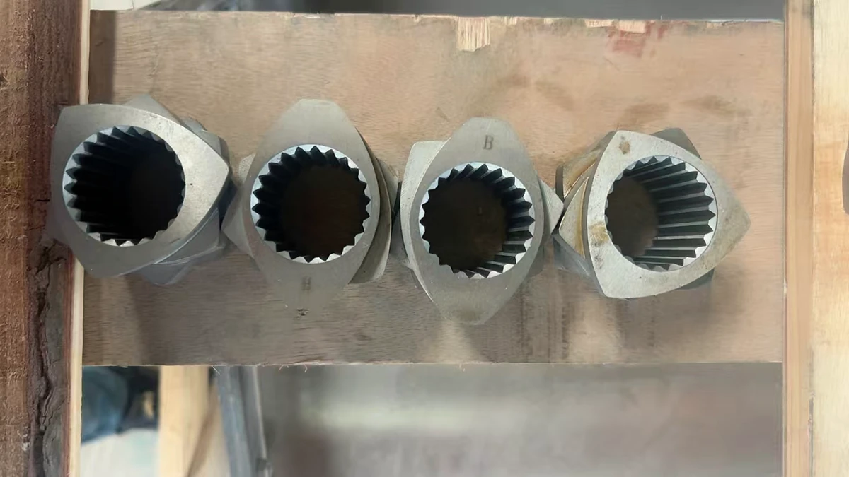
Twin Screw Extruder Elements and Why They Matter
Imagine spending hours fine-tuning barrel temperatures and feed rates, only to end up with inconsistent melt quality or poor dispersion. More often than not, the root cause isn't your process settings - it's the individual segments sitting on your screw shafts. Twin screw extruder elements are the building blocks that determine whether your compounding line delivers precision or frustration.
What Are Twin Screw Extruder Elements
Twin screw extruder elements are modular, interchangeable segments mounted on splined shafts inside a twin screw extruder barrel. Each element is engineered to perform a specific function - conveying, melting, mixing, or pressurizing material - and can be rearranged to create custom screw profiles tailored to individual polymers and applications.
These elements use self-wiping geometry known as Erdmenger profiles, where the lobes of one extruder screw continuously sweep the surface of its partner. This interlocking action prevents material stagnation, ensures consistent residence time, and drives the superior mixing and degassing performance that sets twin screw systems apart from single-screw designs. Every element is defined by measurable parameters - diameter, pitch, flight thickness, and channel depth - that directly control shear input, fill degree, and conveying efficiency.
Why Modularity Matters in Screw Design
Here's what separates twin screw technology from traditional monobloc extrusion screw designs: modularity. A monobloc screw is machined as one continuous piece with a fixed geometry. Change your polymer, filler loading, or throughput target, and you're stuck with a screw that can't adapt.
Modular screw design flips that limitation. Individual conveying elements, kneading blocks, and mixing segments slide onto a common splined shaft, locked in place by torque transmission through the spline interface. Need more dispersive mixing? Swap in wider kneading blocks. Fighting vent flow? Add a reverse element upstream of the vacuum port. This flexibility lets engineers iterate on screw profiles in minutes rather than weeks, turning every extrusion screw into a configurable tool rather than a fixed compromise.
How This Guide Is Organized
This guide follows the same logic a process engineer uses when designing a screw profile from scratch. You'll start with the five functional zones of a twin screw extruder - feed, melting, mixing, venting, and pressure build-up - because understanding where each element belongs is the prerequisite for intelligent screw design. From there, you'll explore element types in detail, compare co-rotating and counter-rotating geometries, and learn how material science and wear patterns influence element life. The final sections translate all of that knowledge into application-specific configurations, troubleshooting strategies, and practical sourcing guidance.
The real power of these modular segments only becomes clear when you see how each functional zone demands a fundamentally different element geometry - and that's exactly where the story picks up.
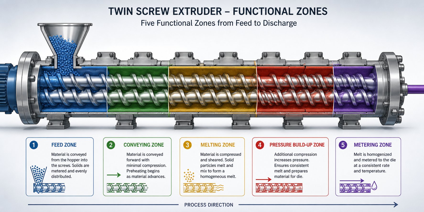
Functional Zones of a Twin Screw Extruder Explained
Every screw profile tells a story from left to right - material enters as a solid, transforms into a melt, gets mixed, loses volatiles, and exits under pressure. That story unfolds across five distinct functional zones inside the extruder barrel, and each zone demands a completely different element geometry to do its job. Misplace a single element type - say, an aggressive kneading block in the feed zone or a wide-pitch conveying element where you need a melt seal - and the entire process suffers. Understanding these zones is the single most important step before you touch a single screw segment.
Feed Zone and Material Intake
The feed zone is where raw material first enters the extruder feed barrel, typically through a gravimetric or volumetric feeder dropping pellets, powder, or flake into an open barrel port. The goal here is simple: pull material in and move it forward without restriction. Any pressure buildup at this stage causes feed bridging, inconsistent throughput, and starve-feeding instability.
To maximize intake capacity, this zone relies on large-pitch (large-lead) conveying elements with deep screw channels. A larger pitch means a greater screw groove volume per revolution, which accommodates bulky, low-density feedstocks and prevents the barrel opening from flooding. You'll notice that most experienced engineers use standard right-handed conveying elements with the widest available lead in this section - typically 1.5D to 2D pitch, where D is the screw outer diameter. If your process includes a downstream side feeder for fillers or additives, the same principle applies: large-lead elements at the side-feed location create a low fill level so incoming material has room to enter the melt stream.
Melting and Plasticating Zone
Once material moves past the feed section, it enters the melting and plasticating zone - the region where solid polymer converts to a processable melt. Two heat sources drive this transformation: external barrel heaters and, more importantly, mechanical shear energy introduced by the screw elements themselves. The element arrangement here directly determines how fast, how uniformly, and at what temperature the material melts.
This zone typically begins with narrow-pitch (small-lead) conveying elements that compress the material and build localized pressure. That pressure pushes polymer against heated barrel walls and into the high-shear gaps between intermeshing screw flights. Following these compressive conveying elements, forward kneading blocks with moderate stagger angles - commonly 30 degrees to 45 degrees - begin working the material through repeated folding and shearing action.
A critical design rule here: don't stack all your kneading blocks in one tight cluster. Concentrating shear elements in a short axial span creates a sharp temperature spike that overshoots your target melt temperature and risks thermal degradation. A better approach alternates forward kneading blocks with short conveying element sections, distributing the total energy input over a longer axial distance. This keeps the material temperature controlled and produces a more uniform melt with lower residual solids.
Mixing, Venting, and Pressure Build-Up Zones
After the polymer is fully molten, the remaining three zones handle the work that defines final product quality.
The mixing zone is where dispersive and distributive mixing occur. Dispersive mixing breaks down agglomerates - pigment clusters, filler bundles, or immiscible polymer domains - using high-shear kneading blocks with 45-degree and 60-degree stagger angles. Distributive mixing then spreads those broken-down particles uniformly throughout the melt, often using specialty elements like toothed (gear-shaped) mixers or turbine mixing elements that split and recombine the melt stream repeatedly. Process engineers balance these two mixing modes by combining kneading blocks with conveying elements in a staggered arrangement, avoiding excessive shear that could degrade heat-sensitive polymers.
The venting and devolatilization zone removes moisture, entrapped air, and volatile byproducts from the melt. Immediately upstream of the vent port, reverse-flighted screw elements or reverse kneading blocks create a melt seal - a fully filled, pressurized plug that prevents volatiles from escaping backward. At the vent port itself, large-lead conveying elements create a low fill level and thin melt layer, exposing a large free surface area to atmospheric or vacuum pressure. This combination - seal upstream, open channel at the port - is what makes efficient degassing possible inside the extrusion barrel.
The pressure build-up (pumping) zone occupies the final section before the die. Here, the screw lead gradually decreases - stepping from standard pitch down to narrow pitch - to compress the melt and generate the die-head pressure needed for stable output. Some profiles use single-flighted elements or wide-flight conveying segments in this zone to boost volumetric pumping efficiency and prevent melt from backing up toward the vent.
| Zone Name | Primary Function | Typical Element Types | Key Process Variables |
|---|---|---|---|
| Feed | Material intake and initial transport | Large-pitch (1.5D-2D) forward conveying elements | Feed rate, bulk density, fill level |
| Melting / Plasticating | Solid-to-melt conversion via shear and barrel heat | Narrow-pitch conveying elements, forward kneading blocks (30-45 degree stagger) | Specific energy input, barrel temperature, melt pressure |
| Mixing | Dispersive and distributive blending of additives and phases | Kneading blocks (45-60 degree stagger), toothed mixing elements, turbine mixers | Shear rate, residence time, melt viscosity |
| Venting / Devolatilization | Removal of moisture, air, and volatiles | Reverse elements (melt seal), large-pitch conveying elements (at vent port) | Vacuum level, melt surface area, fill degree at vent |
| Pressure Build-Up / Pumping | Generate die-head pressure for stable extrusion | Progressively decreasing pitch conveying elements, single-flight elements | Die pressure, melt temperature, output stability |
Each zone in this framework represents a distinct engineering challenge - and the elements chosen for one zone fundamentally constrain what you can do in the next. A weak melt seal before the vent, for example, forces you to reduce throughput to avoid vent flow, which changes the fill degree in every upstream zone. That interconnected nature is precisely why the next step is understanding the individual element families - conveying, kneading, and specialty mixing - at a granular level.
Types of Screw Elements From Conveying to Kneading to Mixing
Zones define where work happens inside the barrel. But the elements themselves - their geometry, pitch, stagger angle, and surface features - determine how that work gets done. Every plastic extruder screw profile is assembled from three primary element families, each engineered for a fundamentally different purpose. Choosing the wrong family, or the wrong variant within a family, is one of the fastest ways to sabotage an otherwise sound process design.
Here's a quick overview of the three families and their sub-types before diving into the details:
- Conveying (Transport) Elements - Large-pitch, standard-pitch, and narrow-pitch variants; single-flighted and double-flighted designs; forward and reverse directions
- Kneading Blocks - Defined by disc count, disc width, stagger angle (30°, 45°, 60°, 90°), and direction (forward, neutral, reverse)
- Specialty Mixing and Restriction Elements - ZME (toothed mixing elements), TME (turbine mixing elements), SME (screw mixing elements), blister rings, and baffle/restriction elements
Conveying Elements and Pitch Variations
Conveying elements are the workhorses of any screw configuration. They look like classic screw flights - helical channels wrapped around a cylindrical core - and their primary job is to transport material axially through the barrel. Simple concept, but the details matter enormously.
The defining parameter is pitch (also called lead), which is the axial distance one flight travels in a single 360-degree revolution. Pitch directly controls two things: how much material the element can carry per revolution and how much pressure it generates along the way.
Large-pitch elements (typically 1.5D to 2D) move material quickly with minimal pressure buildup. They create a low fill degree in the channel, which is exactly what you want in the feed zone or at vent ports where open channel volume is critical. Think of them as the express lane - high throughput capacity, low shear.
Standard-pitch elements (around 1D) strike a middle ground between transport speed and fill level. You'll find these throughout transitional sections of the profile where the goal is to maintain flow continuity without generating excessive shear or starving downstream elements.
Narrow-pitch elements (0.5D to 0.75D) are the opposite extreme. They compress material into a smaller axial space, raising both fill degree and localized pressure. Process engineers place these just upstream of kneading blocks to ensure the melting zone stays fully fed, and in the final pumping section to build die-head pressure.
Direction matters too. Forward (right-handed) conveying elements push material toward the die. Reverse (left-handed) conveying elements push material backward, creating a restriction that builds pressure upstream and generates a melt seal. Reverse elements are short - usually 0.5D to 1D in length - because too much reverse conveying chokes throughput and spikes melt temperature. Their placement before vent ports and at zone boundaries is one of the most impactful screw blade configuration decisions an engineer makes.
Kneading Block Geometry and Stagger Angles
If conveying elements are the workhorses, kneading blocks are the precision instruments. They handle the high-shear, high-intensity work of melting, dispersing, and blending that extruder screws must accomplish in a limited axial space.
A kneading block is a stack of elliptical (bilobal) discs arranged at specific angular offsets along the shaft. Four geometric parameters define every kneading block's behavior:
1. Stagger angle. This is the angular offset between consecutive discs and is the single most influential parameter. Here's how each common angle performs:
- 30° forward - Gentle shear with strong forward conveying action. Material moves through quickly, experiencing moderate mixing. Ideal for heat-sensitive polymers or early-stage plasticating where you want gradual energy input.
- 45° forward - The versatile middle ground. Provides meaningful dispersive mixing while still conveying material downstream. This is probably the most commonly used kneading block configuration across general compounding applications.
- 60° forward - High shear intensity with reduced forward conveying. The wider offset forces material to work harder to pass through the element, increasing residence time and energy input. Effective for breaking up stubborn agglomerates like carbon black clusters or poorly wetted mineral fillers.
- 90° (neutral) - Zero net conveying. Discs are stacked at right angles, so the element neither pushes material forward nor backward. It acts as a restriction, building pressure upstream and maximizing local shear. Excellent for creating melt seals and for demanding dispersive mixing tasks, but use with caution - 90° blocks generate significant heat.
- Reverse stagger - Discs are offset in the opposite rotational direction, actively pushing material backward. This creates an intense restriction and is used sparingly to build melt seals upstream of vent zones or to force extended residence time in reactive extrusion processes.
2. Disc width. Wider discs (sometimes called thick kneading discs) increase the shear zone length that material must pass through, boosting dispersive action. Narrow discs promote distributive mixing by creating more frequent reorientation of the melt as it passes from one disc to the next. A common guideline: use wider discs when you need to break things apart, and narrower discs when you need to spread things evenly.
3. Disc count. More discs per block mean a longer element and greater total energy input. Typical kneading blocks contain five to seven discs, though shorter three-disc variants exist for applications requiring lighter mixing.
4. Overall length. Longer kneading blocks (or sequential blocks stacked together) increase residence time in the mixing zone. However, chaining too many kneading blocks without interrupting conveying elements causes excessive melt temperature rise - the same risk discussed in the melting zone earlier.
Advanced Specialty Mixing and Restriction Elements
Conveying elements and kneading blocks handle the majority of tasks, but certain process challenges call for something more specialized. That's where the advanced element families come in - and this is the territory most engineers never fully explore.
ZME (Toothed Mixing Elements) feature gear-like teeth cut into the element circumference instead of smooth helical flights. Material is forced through the tooth gaps, splitting and recombining the melt stream dozens of times per revolution. This geometry excels at distributive mixing - spreading additives, colorants, and minor-phase domains uniformly throughout the melt without the intense shear that kneading blocks impose. For heat-sensitive formulations like PVC dry blends or low-MFI polyolefins carrying high pigment loads, ZMEs achieve color homogeneity that kneading blocks alone cannot match.
TME (Turbine Mixing Elements) use angled slots or channels cut into a cylindrical body, creating a turbine-like flow pattern that repeatedly divides and recombines the melt. They provide strong distributive mixing with even lower shear input than ZMEs, making them particularly useful for dispersing liquid additives, processing shear-sensitive engineering polymers, or achieving gentle homogenization in reactive extrusion.
SME (Screw Mixing Elements) combine features of both conveying elements and mixing devices. They typically have interrupted flights or slotted channels that allow material to leak between screw channels while still maintaining forward conveyance. The result is distributive mixing that doesn't sacrifice throughput - a valuable trait in high-output compounding lines.
Blister rings are short, cylindrical elements with a very tight radial clearance to the barrel wall. They create a thin-film restriction that forces all material through a narrow annular gap. Blister rings serve as effective melt seals upstream of vent ports and can also function as high-shear dispersive mixing points for breaking down gels or undispersed polymer lumps.
Baffle and restriction elements act as flow dams within the screw profile. Unlike reverse elements that actively push material backward, baffles simply obstruct flow - forcing melt to pass through narrow slots, gaps, or over a raised land. They control residence time distribution and fill level without the aggressive shear that reverse kneading blocks produce.
Each of these specialty elements occupies a specific niche. The real skill lies not in knowing they exist, but in recognizing which process limitation - insufficient distributive mixing, excessive shear sensitivity, poor melt seal integrity - points you toward one design over another. That decision becomes even more nuanced when you factor in the fundamental geometry differences between co-rotating and counter-rotating twin screw systems, where the same element concept can behave in entirely different ways.
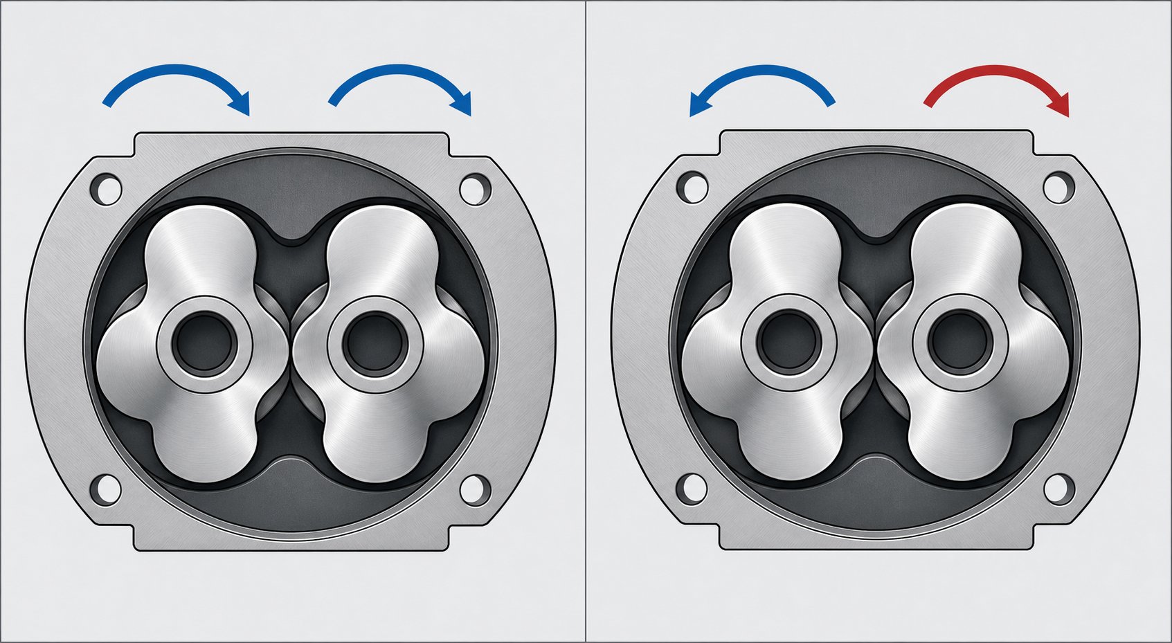
Co-Rotating vs Counter-Rotating Twin Screw Barrel Element Geometry
You've seen how kneading blocks, conveying elements, and specialty mixers each fill a specific role in a screw profile. But here's a question that changes everything about how those elements actually function: which direction are the two screws spinning? The rotational relationship between the shafts - co-rotating or counter-rotating - fundamentally reshapes element geometry, mixing mechanism, and the entire logic behind screw extrusion profile design.
Self-Wiping Intermeshing Co-Rotating Geometry
In a co-rotating twin screw extruder, both shafts rotate in the same direction. This seemingly simple detail imposes a strict geometric constraint on every element mounted on those shafts. The cross-section of each element must follow what's known as the Erdmenger profile - a mathematically derived bilobal shape where the lobe of one screw continuously sweeps the root of its partner. That self-wiping condition is non-negotiable. If the geometry deviates, material stagnates in the intermeshing region, degrades thermally, and contaminates the product stream.
What does this mean in practice? The self-wiping constraint limits the free volume available inside the twin screw barrel for any given outer diameter. The element cross-section is effectively "locked" - you can change pitch, stagger angle, and disc width, but the fundamental lobe profile remains constant across all elements in the system. This standardized geometry is precisely why co-rotating elements are so modular and interchangeable. Every conveying element, kneading block, and mixing segment shares the same cross-sectional envelope, so they slide onto the splined shaft and mesh perfectly with the elements on the adjacent screw.
Mixing in co-rotating systems is driven by intense shear fields that develop both in the screw-to-screw intermeshing zone and in the screw-to-barrel gap. Material is forcibly handed off from one screw to the next at the intermeshing region, following a figure-eight flow path that continuously reorients the melt. This is why kneading block stagger angles carry so much weight in co-rotating profile design - the stagger angle directly controls how much energy each handoff imparts to the material. A 30-degree forward block gently transfers material with moderate shear; a 90-degree neutral block traps material at the intermeshing point and subjects it to maximum deformation before releasing it. The engineer's ability to fine-tune mixing intensity through stagger angle selection is what makes co-rotating systems dominant in compounding, reactive extrusion, and masterbatch production.
Counter-Rotating Element Design Differences
Counter-rotating twin screw extruders spin their shafts in opposite directions, and this changes the physics at the intermeshing region entirely. Instead of material being swept from one screw to the other in a figure-eight path, it gets drawn into the nip between the two screws and compressed - much like material passing through a pair of calender rolls.
This calendering effect is the primary mixing mechanism in counter-rotating systems. Material undergoes repeated compressive and elongational deformation as it passes through the nip, which disperses additives under relatively gentle conditions compared to the high-shear handoff in co-rotating machines. The shear stress between the screws stays lower, and so does the associated viscous heat generation.
Element profiles in counter-rotating systems are not governed by the same self-wiping constraint. The screws intermesh, but they don't wipe each other in the continuous, mathematically strict sense that co-rotating Erdmenger profiles do. This gives counter-rotating element designers more geometric freedom in certain respects - but it also means element interchangeability between brands and even between machine sizes is less standardized. Counter-rotating profiles tend to operate at higher fill degrees as a basic premise, relying on screw rotation itself for stable material transport rather than the drag-flow-dominated conveyance of co-rotating systems.
Imagine processing rigid PVC, a material with a narrow window between melting temperature and decomposition temperature. The low-shear, high-fill operation of counter-rotating extrusion keeps the material temperature under tight control - something that high-shear co-rotating kneading blocks would struggle to achieve without risking degradation.
Choosing the Right Configuration for Your Process
The choice between co-rotating and counter-rotating isn't about which machine is "better." It's about matching the mixing mechanism to the material's requirements. The table below captures the key differences that influence element selection logic:
| Dimension | Co-Rotating | Counter-Rotating |
|---|---|---|
| Self-Wiping Capability | Fully self-wiping (Erdmenger profile); minimal dead zones | Intermeshing but not fully self-wiping; more geometric freedom |
| Primary Mixing Mechanism | High shear at screw-to-screw and screw-to-barrel gaps; figure-eight melt transfer | Calendering (compressive and elongational deformation) at the nip region |
| Shear Intensity | High; controlled via kneading block stagger angles | Low to moderate; controlled via screw speed and nip geometry |
| Throughput Range | Broad; easily scaled from lab to production | Narrower; typically favors high-fill, lower-speed operation |
| Typical Applications | Polymer compounding, masterbatch, reactive extrusion, nanocomposites | Rigid PVC pipes and profiles, sheet extrusion, thermally sensitive formulations |
| Element Interchangeability | Highly standardized across OEMs due to fixed cross-sectional geometry | Less standardized; profiles vary more between manufacturers |
| Residence Time Distribution | Narrow and controllable; self-wiping action minimizes stagnation | Broader; higher fill degree can extend residence time |
For most compounding and blending operations, co-rotating geometry wins on versatility - the ability to dial mixing intensity up or down through element selection alone is hard to beat. Counter-rotating systems earn their place where thermal sensitivity, low-shear dispersion, or the specific rheology of materials like rigid PVC make gentle calendering the smarter path.
Regardless of which configuration sits on your production floor, every element on those shafts shares one thing in common: it must be mounted, secured, and driven through a mechanical interface that transmits torque reliably under extreme conditions. That interface - the splined shaft and its dimensional tolerances - is what makes or breaks the modularity promise, and it's where sourcing decisions start to have real financial consequences.
Modular Screw Construction and OEM Interchangeability
Every conveying element, kneading block, and specialty mixer discussed so far has to do one thing before it can do anything useful: lock onto the shaft and transmit torque without slipping, wobbling, or shearing off under load. The splined shaft is the mechanical backbone of modular screw and barrel systems, and its geometry dictates which elements fit your machine, which suppliers can provide replacements, and how much torque your drive can push through the screw profile before something fails. Get the interface wrong, and a perfectly designed element becomes an expensive paperweight.
Spline Standards and Shaft-Element Interface
Picture the inside bore of a screw element. Instead of a smooth round hole, you'll see a pattern of raised ridges - teeth - running axially along the bore. These teeth mesh with matching grooves machined into the shaft, creating a positive mechanical interlock that transfers rotational force from the gearbox through every element on the assembly. That interlock is the spline, and its profile determines everything about how the barrel extruder transmits torque to the polymer.
Three spline profile types dominate extruder shaft design:
- Involute splines - By far the most common standard in modern twin screw extruders. The tooth profile follows the same involute curve geometry used in gears, which distributes load across a broader contact area and provides inherent self-centering under torque. As detailed in the ANSI/SAE B92.1 standard, involute splines are specified by pressure angle (typically 30 degrees for extruder applications), diametral pitch, and tolerance class. Their widespread adoption across major OEMs - Coperion, KraussMaffei, Leistritz, JSW - means aftermarket suppliers can reference well-documented dimensional standards when manufacturing replacement elements.
- Straight-sided (parallel) splines - An older design with flat-flanked teeth rather than curved ones. These are simpler to machine but concentrate stress at the tooth root corners, limiting torque capacity relative to involute profiles. You'll encounter straight-sided splines primarily on legacy extruders and some smaller laboratory machines.
- Hexagonal lobe (polygonal) profiles - Instead of discrete teeth, these shafts use a multi-lobed polygonal cross-section that mates with a matching bore shape. The contact area is large and continuous, which supports high torque transmission in compact shaft diameters. Some European extruder manufacturers favor this design for high-torque-density platforms.
Torque transmission through any of these interfaces follows a straightforward principle: the driving force acts tangentially on each tooth or lobe face, and the total torque capacity scales with the number of teeth, the effective radius of the spline, and the shear strength of the shaft material. A side-fit spline - where clearance exists between the tooth flanks rather than at the major diameter - allows all teeth to share the load evenly. A major-diameter fit, by contrast, pilots the element concentrically on the shaft but can result in uneven tooth contact, reducing effective torque capacity. Most extruder shafts use side-fit configurations precisely because uniform load sharing matters when you're transmitting thousands of newton-meters through a shaft spinning at 300 to 1,200 RPM.
OEM Interchangeability and Dimensional Tolerances
Here's where sourcing decisions get interesting. When you order a replacement element directly from your extruder's original manufacturer, dimensional compatibility is guaranteed - it's their design, machined to their drawings. But OEM pricing and lead times often push compounding teams toward aftermarket suppliers who reverse-engineer elements to match the original specifications. That approach works well, provided the critical dimensional parameters are verified before production begins.
Aftermarket manufacturers replicate extruder screws and barrels using one of three methods: working from OEM part numbers and published specifications, manufacturing to customer-supplied engineering drawings or CAD files, or reverse-engineering from physical samples or measured dimensions. Suppliers like NANHAIYA, for example, produce modular screw segments, kneading blocks, and screw elements manufactured to drawings, samples, or measured dimensions - covering compounding, pelletizing, masterbatch, and recycling applications across a wide range of extruder platforms. This flexibility is especially valuable when sourcing replacements for discontinued models or machines that have been modified over years of service.
Regardless of which supplier you choose, the following dimensional and tolerance checkpoints must be verified before approving any replacement element. Missing even one can result in a part that either won't fit the shaft or underperforms in the process:
- Spline profile type and tooth count - Confirm whether the shaft uses involute, straight-sided, or polygonal geometry, and verify the exact number of teeth or lobes. A mismatch here means the element physically cannot mount on the shaft.
- Bore diameter (inner diameter) - Measure the element's bore to ensure it matches the shaft's major spline diameter within the specified tolerance class. Too tight and the element won't slide on; too loose and it introduces radial play that accelerates wear.
- Outer diameter (OD) - The element's flight tip or lobe tip diameter must match the barrel bore with the correct radial clearance - typically 0.1 to 0.3 mm per side, depending on the extruder model and processing conditions. An oversized OD scores the barrel liner; an undersized OD increases leakage flow and reduces mixing efficiency.
- Element length and length increments - Most OEMs design their elements in standardized length increments (commonly multiples of the screw diameter or fixed millimeter steps). Replacement elements must match these increments exactly, because even a 1 to 2 mm cumulative error across a full screw build can misalign vent ports, feed openings, and barrel section joints.
- Pitch, stagger angle, and disc count - For conveying elements, verify the pitch matches the original specification. For kneading blocks, confirm the stagger angle, number of discs, and disc width. These parameters define the element's process function - substituting a 45-degree block where a 60-degree block should be changes mixing intensity significantly.
- Surface finish and flight edge quality - Flight lands and kneading disc tips should meet specified surface roughness values (typically Ra 0.4 to 0.8 micrometers). Rough surfaces increase friction, accelerate barrel wear, and can cause polymer degradation at the element-to-barrel interface.
- Material grade and hardness - Verify that the replacement element is manufactured from the correct steel grade with the specified hardness range. A nitrided steel element substituted into a position that requires PM-HIP tool steel will wear out in a fraction of the expected service life.
- Concentricity and runout - The element's outer diameter must be concentric to the bore within tight tolerances - usually 0.02 to 0.05 mm total indicator runout. Excessive runout creates uneven barrel contact, localized wear, and vibration at high screw speeds.
Any reputable supplier will confirm these parameters in a formal drawing review before machining begins and provide a dimensional inspection report with the finished parts. If a supplier quotes without asking for this level of detail, they're either making assumptions or planning to ask later - both of which delay delivery and increase the risk of receiving parts that don't fit.
Practical Advantages of Modular Construction
Why go through all this dimensional rigor instead of simply ordering a one-piece monobloc screw? Because modularity pays for itself in three ways that monobloc designs simply cannot match.
Rapid process optimization. Imagine you're compounding a new glass-fiber-reinforced nylon formulation and the initial screw profile produces acceptable dispersion but excessive melt temperature. With modular elements, you can pull the screws, swap two aggressive 60-degree kneading blocks for gentler 45-degree blocks, reassemble, and run a trial - all within a single maintenance window. On a monobloc screw, that same adjustment requires ordering an entirely new screw with a different flight geometry, waiting weeks for delivery, and hoping the new design solves the problem on the first try.
Targeted maintenance and cost control. Wear doesn't happen uniformly along the screw. Kneading blocks in the melting zone and elements at the glass-fiber feed point degrade far faster than conveying elements in the pressure build-up section. Modularity lets you replace only the worn segments rather than scrapping the entire screw assembly. Over the life of a production line, this targeted replacement strategy can reduce screw and barrel consumable costs by 40 to 60 percent compared to monobloc replacement.
Application flexibility across product lines. Many compounding operations run multiple formulations on the same extruder - unfilled polyolefins one week, 40-percent-talc-filled polypropylene the next, followed by a color masterbatch run. Each product benefits from a different screw profile. With a library of modular elements on hand, the same machine can be reconfigured for each application without purchasing dedicated screws for every formulation. This versatility is what makes modular extruder screws and barrels the standard across compounding, pelletizing, masterbatch, and recycling operations worldwide.
The mechanical interface and dimensional precision covered here ensure that modular elements fit and transmit torque reliably. But fitting the shaft is only half the durability equation - the element's surface must also survive the relentless abrasion, corrosion, and fatigue that polymer processing inflicts hour after hour. That survival depends entirely on what the element is made of.
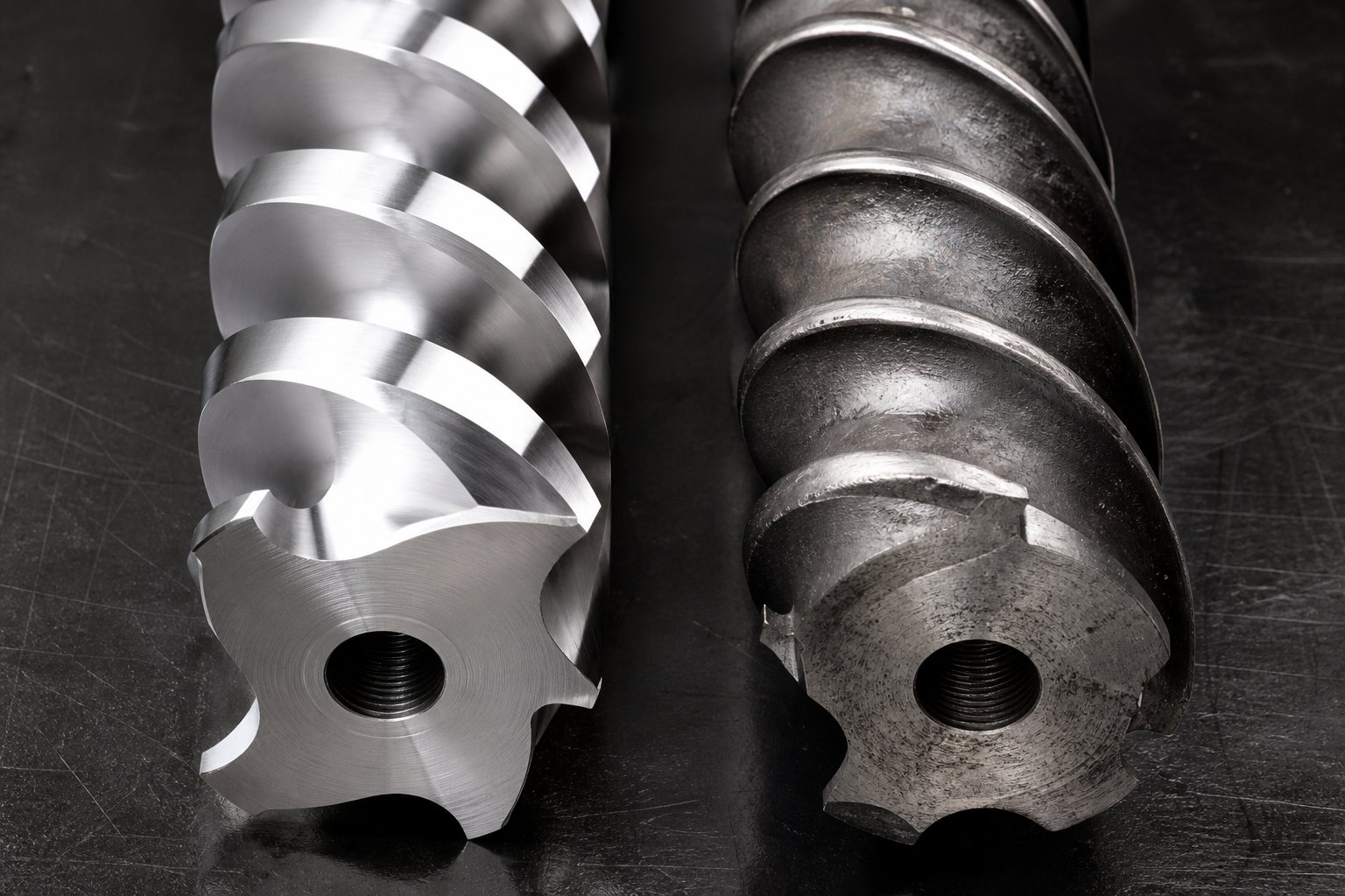
Element Materials and Wear Mechanisms
A perfectly designed screw profile mounted on precisely toleranced shafts still has an expiration date. The polymer melt, fillers, and chemical byproducts flowing through the extrusion screw barrel attack element surfaces relentlessly - grinding down flight tips, etching kneading disc faces, and fatiguing spline roots under cyclic torque. How long each element resists that assault depends almost entirely on the metallurgy it's made from. And knowing when an element has degraded past its useful limit - before it damages the barrel or ruins your product - requires a structured inspection approach that most plants never formalize.
Element Materials From Tool Steel to Powder Metallurgy
Screw element materials span a wide performance and cost range, and the right choice depends on what's flowing through the extruder barrels - unfilled polymers, abrasive mineral compounds, corrosive off-gassing resins, or some combination of all three.
Through-hardened tool steels are the baseline. Grades like AISI 4140 or 4340, heat treated to 28-34 HRC, offer decent strength and machinability at low cost. They work for general-purpose extrusion of unfilled or lightly filled polymers where wear rates are modest. However, their hardness ceiling limits service life in any application involving abrasive additives.
Nitrided steels take a step up by diffusing nitrogen into the element surface to create a hard case layer - typically 60-70 HRC on grades like DIN 1.8550 (34CrAlNi7) - over a tougher core. This gives excellent surface wear resistance without making the entire element brittle. Nitriding is a cost-effective upgrade for moderate-wear applications and remains the most widely used treatment across standard compounding lines. The limitation? The nitrided case is thin - usually 0.3 to 0.5 mm deep - so once wear penetrates the hardened layer, the softer substrate underneath erodes rapidly.
Powder metallurgy (PM) tool steels represent a fundamentally different manufacturing approach. Instead of casting a large ingot and hot-rolling it into bar stock, PM steels start as atomized metal powder consolidated under high temperature and pressure through hot isostatic pressing (HIP). Each powder particle solidifies so quickly that carbide segregation - the coarse, banded carbide networks that plague conventional tool steels - never has time to develop. The result is a microstructure with fine, uniformly distributed carbides throughout the entire cross-section.
Why does that matter for screw elements? Three reasons:
- Superior wear resistance - The uniform carbide distribution means abrasive particles encounter hard carbide phases no matter which direction they contact the surface, eliminating the weak "lanes" between coarse carbide bands where conventional steels wear preferentially.
- Higher toughness at equal hardness - PM steels can be heat treated to 60-64 HRC while retaining significantly better impact resistance than conventional tool steels at the same hardness. This matters because screw elements endure both abrasive sliding and repetitive mechanical shock from intermeshing contact.
- Isotropic properties - Conventional wrought steels exhibit directional property differences (anisotropy) because hot working aligns carbide stringers along the rolling direction. PM steels are isotropic, performing identically regardless of loading direction - critical for bilobal element profiles that experience multi-axial stress during rotation.
High-vanadium PM grades like CPM 10V are the go-to choice for processing glass-fiber-reinforced compounds, mineral-filled masterbatch, and other highly abrasive formulations where conventional steels would wear out in weeks. The tradeoff is cost: PM tool steels typically run 1.5 to 3 times the price of conventional equivalents, so they earn their premium only when extended service life and reduced downtime justify the investment.
Tungsten-carbide-based materials push wear resistance even further. Elements can be manufactured entirely from cemented tungsten carbide (WC-Co) or, more commonly, coated with tungsten-carbide thermal spray layers (HVOF coatings) applied over a steel substrate. These surfaces achieve hardness levels above 1,200 HV - far beyond any steel - and excel in the most abrasive environments: high-glass-fiber loadings, ceramic-filled compounds, and recycling lines processing contaminated streams. Full tungsten carbide elements are expensive and brittle, so their use is usually limited to the highest-wear positions in the screw profile, such as kneading blocks in the melting zone or elements at side-feeder intake points.
Ceramic and hard-chrome coatings offer a surface-treatment alternative. Chrome plating provides modest corrosion and wear resistance at low cost, while advanced ceramic coatings (chromium oxide, aluminum oxide) deposited by plasma spray can deliver hardness approaching carbide levels. These coatings protect extrusion barrels and element surfaces in corrosive environments - think PVC processing, reactive extrusion with acid catalysts, or fluoropolymer compounding - where chemical attack would degrade even hardened steel.
Four Wear Mechanisms That Degrade Screw Elements
Material selection only makes sense when you understand what's destroying the elements in the first place. Four distinct wear mechanisms operate inside every twin screw extruder, often simultaneously, and each one demands a different metallurgical response.
Abrasive wear is the most common culprit. Hard particles embedded in the polymer melt - glass fibers, calcium carbonate, talc, titanium dioxide, wood flour, and recycled contaminants - act like microscopic cutting tools, grinding down flight tips and kneading disc edges with every screw revolution. The sharp machined corners of screw and kneading elements appear rounded, smooth, and occasionally polished when subjected to prolonged abrasion. Wear severity depends on filler hardness, particle size and shape, loading percentage, screw speed, and total throughput. This type of wear correlates with the amount of material processed rather than clock hours of operation - an important distinction for scheduling inspections.
Adhesive wear occurs when metal surfaces rub directly against each other under insufficient lubrication - and in a twin screw extruder, the polymer melt is the lubricant. When screws are left rotating at speed without material flow - during startup, shutdown, or between production runs - the melt film between the screw flights and the barrel wall thins and eventually breaks down. The result is metal-to-metal contact that flattens flight outer diameters and scores the barrel wall. If the shafts deflect and the screws contact each other, scratches appear on the tips, flanks, and roots of the screw flights. Insufficient shaft support, misalignment, bearing failure, or a bent shaft all accelerate adhesive wear.
Corrosive wear results from chemical attack by the process environment itself. Certain polymers release aggressive byproducts during processing - PVC generates hydrochloric acid, some flame retardants off-gas halogenated compounds, and reactive extrusion processes can expose elements to acidic or alkaline catalysts. Corrosion causes the metal surface to appear dimpled or pitted, weakening the element structure and accelerating subsequent abrasive or adhesive damage. Even condensation on chilled barrel sections can initiate corrosion if moisture lingers on unprotected steel surfaces.
Fatigue wear is the slow, silent mechanism. Every screw revolution subjects elements to cyclic loading - fluctuating torque at the spline interface, bending stresses from melt pressure, and thermal cycling as the element heats and cools across production runs. Over thousands of operating hours, these repeated stress cycles nucleate microscopic cracks at stress concentrators like spline roots, flight-to-core transitions, and kneading disc edges. Eventually, material flakes away in small fragments - a process called spalling - leaving pitted, rough surfaces that degrade mixing performance and can release metallic contamination into the product.
| Wear Mechanism | Causes | Affected Elements | Prevention Strategy |
|---|---|---|---|
| Abrasive | Glass fiber, mineral fillers, TiO2, wood flour, recycled contaminants | Kneading blocks in melting zone, elements at side-feeder intake, narrow-pitch conveying elements | PM tool steel or tungsten carbide elements in high-wear positions; reduce screw speed where possible; optimize filler feed point |
| Adhesive | Metal-to-metal contact during dry running, shaft deflection, misalignment, bearing failure | Flight tips of conveying elements, intermeshing surfaces of kneading blocks, barrel liners | Never run screws at speed without material flow; automatic shutdown protocols below minimum torque; verify shaft alignment at assembly |
| Corrosive | Acid off-gassing (PVC, flame retardants), reactive extrusion catalysts, moisture condensation on chilled barrels | Venting zone elements, elements downstream of reactive injection, barrel liners near vent ports | Corrosion-resistant alloys or ceramic coatings; tight temperature control to prevent condensation; proper purging between runs |
| Fatigue | Cyclic torque loading, thermal cycling, vibration from unbalanced elements or high-speed operation | Spline roots, flight-to-core transitions, kneading disc edges, reverse elements under high back-pressure | PM steels with superior toughness; avoid exceeding rated torque; replace elements before crack propagation becomes visible |
Inspection Methods and Replacement Criteria
Knowing these wear mechanisms exist is only useful if you can detect and measure the damage before it compromises product quality or cascades into barrel damage. A structured inspection routine catches problems early and turns reactive emergency shutdowns into planned maintenance events.
Measuring flight outside diameter (OD). This is the most direct indicator of element wear. Using an outside micrometer or calibrated caliper, measure the flight tip diameter at multiple axial positions along each element and at more than one angular orientation. Compare each reading against the original drawing dimension or a documented new-condition baseline. For modular twin screws, also inspect shafts, keys, element bores, and intermeshing surfaces - bore wear can be just as consequential as flight wear.
Checking radial clearance between screw and barrel. This is where individual element measurements connect to system-level performance. The critical calculation is straightforward:
Diametral clearance = measured barrel ID - measured screw element OD. Radial clearance = diametral clearance / 2.
Always confirm whether your OEM specification uses diametral or radial clearance - confusing the two can double or halve the interpreted result. Measure the barrel bore at corresponding axial locations using a calibrated bore gauge, and check for ovality (the difference between the largest and smallest bore readings at different angles in the same cross-section). Barrel wear that creates an oval bore concentrates contact on two opposing points, accelerating both element and liner degradation.
Visual inspection for pitting, scoring, and surface damage. After cleaning, examine element surfaces under good lighting for signs of the four wear mechanisms. Abrasive wear shows as rounded, polished edges where sharp corners once existed. Adhesive wear leaves score marks - linear scratches aligned with the direction of contact. Corrosive wear produces a dimpled, pitted surface texture. Fatigue damage appears as spalling - small craters where surface material has flaked away. Photograph and document any findings alongside dimensional measurements for trend tracking.
When should elements be replaced? There's no single universal threshold, because allowable clearance depends on screw diameter, polymer viscosity, operating pressure, and product quality requirements. However, practical guidelines exist. One manufacturer recommends replacement when screw elements lose approximately 5% of their starting diameter over three-quarters of the element length, with corresponding barrel liner replacement at roughly 5% bore diameter increase over a length of 1D. More broadly, replacement is justified when a measurable reduction in output, mixing quality, or process stability persists after basic process checks - feed system, barrel heaters, thermocouples, screen pack, and die condition - have been ruled out as causes.
The smartest approach is trend-based. Record measurements at fixed axial positions during every inspection, calculate wear rate per unit of throughput, and project when clearance will reach your accepted limit. This lets you order replacement elements in advance and schedule the swap during a planned shutdown rather than scrambling after quality complaints start hitting the line. Always evaluate the extrusion screw barrel as a matched pair - installing a new element into a badly worn barrel, or vice versa, leaves excessive clearance that shortens the life of the new component.
Material choice and wear management determine how long your elements last. But element longevity matters only if the screw profile is configured correctly for the application in the first place. A glass-fiber compounding line, a color masterbatch operation, and a post-consumer recycling process each demand radically different element arrangements - and getting those arrangements right is where process engineering meets practical application knowledge.
Application-Specific Screw Profile Configuration
Knowing your elements and understanding wear is essential - but all of that knowledge sits idle until it's applied to a real formulation on a real production line. A screw profile for polymer compounding with 40% calcium carbonate looks nothing like one designed for post-consumer plastic recycling or a reactive extrusion process with strict residence time requirements. Each application prioritizes different mixing modes, thermal constraints, and devolatilization demands, which means the element sequence - what goes where, and why - changes dramatically from one process category to the next.
What follows is practical, process-specific guidance that connects element types to the outcomes they produce. Think of each configuration as a starting framework rather than a rigid recipe. Every material has its quirks, and fine-tuning is always part of the process.
Compounding and Masterbatch Screw Profiles
General polymer compounding is the broadest category, covering everything from mineral-filled polypropylene to impact-modified engineering resins. The central challenge in any twin screw compounding extruder is balancing dispersive and distributive mixing. As compounding experts have pointed out, a material can be distributed but not dispersed - producing blotchy, nonuniform compounds with additive-rich pockets - or dispersed but not distributed, leaving well-broken-down particles concentrated in one region of the melt. A successful screw profile for polymer compounding addresses both modes in sequence.
For a typical filled compound (talc, CaCO3, or glass fiber in a polyolefin or nylon carrier), the profile follows a clear logic: melt the polymer first, introduce the filler, disperse agglomerates with high-shear elements, then distribute the broken-down particles uniformly before building die pressure. Here's a simplified element sequence:
- Feed zone (barrels 1-2): Large-pitch conveying elements (1.5D-2D) for unrestricted material intake
- Melting zone (barrels 3-4): Narrowing-pitch conveying elements transitioning to forward kneading blocks (30° then 45° stagger), closed with a 60° or neutral (90°) block to ensure full melting
- Side-feed intake (barrel 5): Large-pitch conveying elements reopening the channel to accept filler from the side stuffer
- Dispersive mixing zone (barrels 6-7): Wide-disc kneading blocks at 45° and 60° stagger angles to break filler agglomerates, followed by a neutral or short reverse block to maintain high fill degree
- Distributive mixing zone (barrel 8): Narrow-disc forward kneading blocks or toothed mixing elements (ZME) to spread filler uniformly without adding excessive shear
- Venting zone (barrel 9): Reverse element for melt seal, then large-pitch conveying elements under vacuum port
- Pressure build-up (barrels 10-11): Progressively narrowing-pitch conveying elements to generate stable die pressure
A critical point from experienced screw designers: ending your mixing sections with either a neutral kneading block or a short reverse element ensures the mixing zone stays highly filled, which makes mixing far more efficient. A mixing section built entirely from forward-conveying kneading blocks tends to run partially empty, whipping the polymer instead of shearing it - raising melt temperature while achieving surprisingly little actual mixing.
Masterbatch production presents a different balancing act. Pigment concentrations can reach 40-70% by weight, yet the carrier resin - often a low-viscosity polyethylene or EVA - is thermally delicate. The screw chemistry here revolves around intense dispersive mixing to break down pigment agglomerates (especially carbon black, which has a high affinity to agglomerate because individual particles fuse into aggregates during combustion) while limiting total energy input to protect the carrier.
The typical masterbatch profile concentrates its most aggressive elements in a single well-defined mixing section rather than distributing shear across the full screw length:
- Feed zone: Large-pitch conveying elements; pre-blended carrier and pigment fed together or split between main hopper and side feeder
- Melting zone: Moderate kneading blocks (30°-45° forward) - just enough to plasticize the carrier without overheating it before pigment incorporation
- Primary dispersive mixing (2-3 barrel lengths): Wide-disc kneading blocks at 60° forward and 90° neutral, often in two sequential clusters separated by a short conveying section to allow brief cooling. This is where agglomerates break down to their ultimate particle size
- Distributive mixing: Toothed mixing elements (ZME) or narrow-disc forward kneading blocks to spread dispersed pigment evenly. ZMEs are particularly effective here because they split and recombine the melt stream repeatedly without the intense shear that kneading blocks impose
- Pressure build-up: Narrowing-pitch conveying elements feeding the pelletizing die
Sounds intense? It is - but the key insight is that a well-designed masterbatch profile limits high-shear zones to only the locations where dispersion is physically required, then immediately transitions to gentler distributive elements. Overextending the aggressive section raises melt temperature past the carrier's stability window and can actually re-agglomerate pigment through thermal degradation of the wetting layer.
Recycling and Devolatilization Configurations
Post-consumer and post-industrial plastic recycling throws problems at a screw profile that virgin compounding never encounters: inconsistent feed bulk density, mixed polymer contamination, residual moisture, printing inks, adhesive residues, and volatile organic compounds trapped in degraded resin. A successful plastic recycling extruder screw design must tolerate this variability while still producing clean, degassed pellets.
Devolatilization dominates the profile. Most recycling screw configurations include two or even three vent ports - one atmospheric and one or two under vacuum - to extract the wide spectrum of volatiles that contaminated feedstock releases. Each vent requires its own upstream melt seal (reverse element or reverse kneading block) and a low-fill-degree conveying section at the port. That means a recycling profile dedicates significantly more barrel length to venting infrastructure than a standard compounding profile does.
- Feed zone: Extra-long large-pitch conveying section (2-3 barrel lengths) to accommodate low-bulk-density flake or regranulate without bridging
- Melting zone: Moderate kneading blocks (30°-45° forward), kept gentler than compounding profiles to avoid overworking already-degraded polymer chains
- First vent (atmospheric, barrel 5-6): Reverse element for melt seal, large-pitch conveying under the vent to flash off surface moisture and light volatiles
- Mixing zone (barrel 7): Forward kneading blocks (45°) and distributive elements for homogenization; intensity kept moderate since the goal is blending, not aggressive dispersion
- Second vent (vacuum, barrel 8-9): Reverse element seal, large-pitch conveying under deep vacuum (typically 50-200 mbar absolute) to strip remaining volatiles, inks, and odor compounds
- Optional third vent (vacuum, barrel 10): For heavily contaminated streams requiring additional volatile removal
- Pressure build-up (barrels 11-12): Narrowing-pitch conveying with optional melt filtration before pelletizing
A practical detail that separates experienced recycling operations from struggling ones: the conveying sections at each vent port must be long enough to create a genuinely thin melt layer with a large exposed surface area. Short vent sections result in a thick, slow-moving melt pool that traps volatiles beneath the surface, sending them straight through to the pellet. When engineers complain about persistent odor in recycled pellets, insufficient vent section length is one of the most common root causes.
Devolatilization-intensive processes beyond recycling - such as solvent stripping from solution polymerization, moisture removal from hygroscopic engineering plastics, or monomer extraction from polycondensation residues - follow the same fundamental principle but push it further. These applications may use four or more sequential vent stages, each operating under progressively deeper vacuum. The screw profile becomes a repeating pattern: melt seal, low-fill conveying under vacuum, melt seal, low-fill conveying under vacuum. Mixing zones shrink to short homogenization sections between vents, because the primary goal isn't blending - it's mass transfer of volatiles from the bulk melt to the free surface.
Reactive Extrusion and Specialty Profiles
Reactive extrusion uses the twin screw extruder as a continuous chemical reactor. Applications include maleic anhydride grafting of polyolefins, peroxide-initiated controlled degradation (vis-breaking), chain extension of recycled PET, and polymerization of caprolactam to nylon 6. The screw profile must control something that compounding profiles largely ignore: residence time and its distribution.
In reactive extrusion, the screw chemistry is literal - chemical reactions proceed as functions of temperature, time, and mixing intensity. Too short a residence time and the reaction doesn't reach completion. Too long and side reactions produce unwanted byproducts, crosslinking, or degradation. Uniformity of residence time matters just as much as its average value, because any material that passes through faster or slower than the target exits the extruder at a different conversion level, creating product variability.
- Feed and melting zone: Standard configuration - large-pitch conveying into moderate kneading blocks for melting
- Reactant injection point (barrel 4-5): Large-pitch conveying elements to accept liquid peroxide, grafting agent, or chain extender from an injection pump; followed immediately by distributive mixing elements (ZME or narrow-disc kneading blocks) to disperse the reactant uniformly into the melt before it can concentrate locally and cause hot spots or gel formation
- Reaction zone (barrels 6-9): A carefully calibrated sequence of forward conveying elements with intermittent neutral kneading blocks or reverse elements that create partially filled sections alternating with fully filled sections. The fully filled zones provide the sealed, pressurized conditions needed for the reaction; the partially filled zones allow volatile byproducts to migrate toward vent ports. The total length of this section, combined with screw speed and throughput rate, sets the mean residence time
- Devolatilization (barrel 10): Reverse element seal and vacuum vent to strip unreacted monomer, peroxide decomposition products, or water of reaction
- Pressure build-up (barrels 11-12): Narrowing-pitch conveying for die pressure
The distinguishing feature of reactive profiles is the extended length of partially restrictive zones that hold material inside the barrel long enough for the reaction to proceed. Unlike a compounding profile where you want material to exit quickly to minimize thermal history, reactive extrusion deliberately slows the material down. Sealing elements - reverse kneading blocks, blister rings, or reverse conveying segments - placed at strategic intervals create the back-pressure that controls fill level and, by extension, residence time in each reaction sub-zone.
One subtlety that trips up newcomers: aggressive dispersive mixing is usually counterproductive in reactive extrusion. High shear raises melt temperature unpredictably, accelerating reaction kinetics in some zones while causing thermal degradation in others. The ideal reactive profile uses moderate, distributed mixing - enough to keep reactant concentrations uniform without generating the intense shear peaks that kneading-heavy compounding profiles produce.
Each of these application profiles - compounding, masterbatch, recycling, devolatilization, and reactive extrusion - is communicated to machine operators, process engineers, and element suppliers through a standardized screw configuration chart. Reading those charts, interpreting element codes, and translating between different manufacturers' naming conventions is a skill set that bridges the gap between profile design on paper and physical screws on the shaft.
Screw Element Nomenclature and Notation Standards
You've just designed a screw profile on paper - the right kneading block angles, the perfect vent-seal placement, a carefully tuned pressure build-up section. Now you need to order parts. You open a catalog, and the first element listed reads "KB 45/5/42." The next supplier's catalog calls what looks like the same part "KBW-45/5/30 R." A third lists it as "KBF-5-45." Same functional element, three completely different codes. Welcome to the world of twin screw extruder element codes, where every OEM speaks its own dialect of the same technical language.
Understanding the screw element naming convention each manufacturer uses isn't optional - it's a practical necessity. Misread a code, and you'll order a 30-degree forward kneading block when you needed a 60-degree neutral. Worse, you'll struggle to communicate your screw profile to aftermarket suppliers, toll compounders, or process engineers at sister plants running different extruder brands. This section breaks down how element nomenclature works, how to translate between systems, and how to read a full screw profile configuration chart.
How to Read Element Nomenclature Codes
Despite the apparent chaos, every screw element naming convention follows a consistent internal logic. Each code encodes three to five pieces of information in a compressed alphanumeric string: element type, primary geometric parameter, secondary geometric parameter, length, and direction. The order and abbreviations vary by manufacturer, but the underlying data is always the same.
Take a Brabender-style nomenclature as what is an example of a screw element code system. A conveying element labeled SE-20/20 R decodes as follows:
- SE - Screw Element (conveying type)
- 20 (first number) - Pitch in millimeters (the axial distance per full flight revolution)
- 20 (second number) - Length of the segment in millimeters
- R - Direction of rotation: Right-handed (forward conveying)
A kneading block in the same system uses a different structure. KBW-45/5/30 R means:
- KBW - Kneading Block with full-disc Width on both sides (as opposed to KP, which designates a kneading block with half-disc widths)
- 45 - Stagger angle in degrees between consecutive discs
- 5 - Number of discs in the block
- 30 - Total length of the element in millimeters
- R - Right-handed (forward conveying direction)
Toothed mixing elements follow yet another pattern. Z 8/3/20 breaks down as:
- Z - Toothed mixing element (from the German "Zahnmisch")
- 8 - Number of teeth per circumference
- 3 - Number of tooth rows along the element length
- 20 - Length in millimeters
Notice the pattern: the letter prefix always tells you what family the element belongs to, and the numbers that follow describe its geometry. Direction indicators (R for right/forward, L for left/reverse) appear on conveying and kneading elements but are absent on neutral designs like the toothed mixer, which has no inherent conveying bias.
Other OEMs encode the same information differently. Coperion-style codes for conveying elements might read 24/24 SK or 42/42, where the prefix is dropped and the pitch/length pair leads. CPM century extrusion platforms and Leistritz systems each have their own shorthand. A Leistritz kneading block might appear as KB 5-2-30-60, where the numbers represent disc count, flights, length, and stagger angle in a different sequence than Brabender's convention.
Translating Between OEM Naming Conventions
The real headache arrives when you're sourcing elements from one supplier for a machine built by another. Imagine you're running a Coperion ZSK and want to replicate a screw profile originally documented for a KraussMaffei Berstorff machine. The profile drawing lists element codes in the Berstorff convention, but your replacement elements supplier works from Coperion-style nomenclature. Without a translation layer, errors are inevitable.
The key is to stop thinking in codes and start thinking in parameters. Every element code, regardless of manufacturer, describes the same set of physical characteristics. Strip away the abbreviations, and you're always asking five questions:
- What type of element is it? (Conveying, kneading, toothed mixer, reverse, etc.)
- What is the primary geometric parameter? (Pitch for conveying elements; stagger angle for kneading blocks; tooth count for mixers)
- What is the length?
- What is the direction? (Forward, reverse, or neutral)
- Are there secondary parameters? (Disc count, disc width type, number of flights)
When communicating with a supplier who uses a different naming system, provide these five parameters explicitly alongside whatever code you have. A purchase order that reads "KBW-45/5/30 R equivalent: forward kneading block, 45-degree stagger, 5 discs, full-width discs, 30 mm total length" eliminates ambiguity regardless of which catalog the supplier references.
| Element Code | Element Type | Pitch or Stagger Angle | Length (mm) | Direction |
|---|---|---|---|---|
| SE-20/20 R | Conveying (screw element) | 20 mm pitch | 20 | Forward (right) |
| SE-10/10 L | Reverse conveying | 10 mm pitch | 10 | Reverse (left) |
| SK-40/40 R | Thrust-edge conveying (high volume) | 40 mm pitch | 40 | Forward (right) |
| KP-45/5/20 R | Kneading block (half-disc width) | 45° stagger angle, 5 discs | 20 | Forward (right) |
| KBW-45/5/30 L | Kneading block (full-disc width) | 45° stagger angle, 5 discs | 30 | Reverse (left) |
| Z 8/3/20 | Toothed mixing element | 8 teeth, 3 rows | 20 | Neutral |
| KB 45/5/42 (alt. convention) | Kneading block | 45° stagger angle, 5 discs | 42 | Varies by suffix |
Reading a Screw Profile Configuration Chart
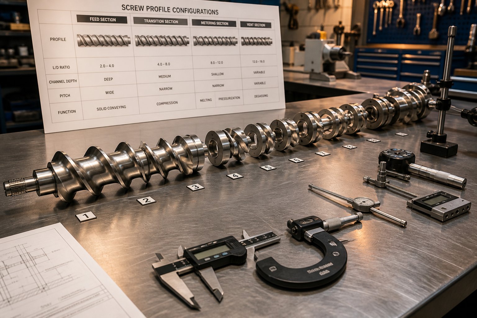
A screw profile configuration chart - sometimes called a screw layout drawing or screw build sheet - is the master document that maps every element on both shafts from feed end to discharge end. It's the blueprint that an operator follows when assembling a screw and the reference document that a process engineer uses to communicate a profile to colleagues or suppliers.
A typical configuration chart is structured as a horizontal diagram with the barrel sections drawn to scale along the top. Below each barrel section, element codes are listed in sequence from left (feed) to right (die). Each element's length is represented proportionally so that the chart visually shows where kneading blocks cluster, where conveying sections span, and where reverse elements create melt seals relative to vent ports, feed openings, and barrel joints.
Here's what to look for when reading one:
- Barrel zone numbering - Barrels are numbered sequentially (1, 2, 3...) from the feed throat to the die adapter. Temperature set points are often noted above each zone.
- Element sequence - Listed below the barrel zones, each element code appears in the exact order it sits on the shaft. The cumulative length of all elements must equal the total screw length, and any discrepancy signals an assembly error.
- Port locations - Feed ports, side-feeder openings, liquid injection points, and vent ports are marked at their corresponding barrel positions. These landmarks anchor the profile - you can't move a vent seal element away from the vent port, so the entire upstream configuration must fit within the available barrel length.
- Left/right shaft distinction - On some charts, both shafts are drawn separately because certain elements (particularly reverse kneading blocks) may differ between driving and driven shafts. On co-rotating systems with identical screw builds on both shafts, a single row of element codes suffices.
When you receive a configuration chart from a machine builder, toll compounder, or process licensor, the first thing to do is verify that you can identify every element code using the manufacturer's naming convention. If any code is unfamiliar, decode it into the five universal parameters - type, geometry, length, direction, and secondary features - before attempting to source or modify the profile. That translation step is the bridge between a drawing on paper and a functioning screw assembly on the shop floor.
Reading and interpreting these charts fluently is especially critical when something goes wrong in production. A surging output, a vent that keeps flooding, or a melt temperature that won't come down - each of these problems points back to specific elements at specific positions in the profile, and the configuration chart is how you pinpoint exactly which segments to swap, reposition, or replace.
Troubleshooting and Strategic Element Sourcing
A screw profile configuration chart tells you what's on the shaft. Production data tells you whether it's working. When output surges unpredictably, pigment agglomerates show up in pellets, polymer oozes out of vent ports, or melt temperature climbs 20 degrees above your target, the configuration chart becomes your diagnostic map - and the elements on it become your primary corrective tools. Twin screw extruder troubleshooting is ultimately about connecting observable symptoms to specific element positions, then making targeted modifications that resolve the root cause without creating new problems elsewhere in the profile.
Diagnosing Mixing, Surging, and Degradation Issues
Five processing problems account for the overwhelming majority of element-related performance failures. Each one leaves a distinct fingerprint that points toward a specific category of screw profile modification.
Poor dispersive mixing shows up as undispersed agglomerates - visible pigment specks, glass fiber bundles that didn't separate, or filler clusters that reduce mechanical properties in the finished part. The root cause is almost always insufficient shear energy in the mixing zone. Either the kneading blocks are too gentle (30-degree stagger where 60-degree is needed), too short (three-disc blocks where five-disc blocks would sustain shear longer), or the mixing section isn't running fully filled. Remember: a mixing zone built entirely from forward-conveying kneading blocks tends to run partially empty, whipping the melt instead of shearing it. Adding a neutral (90-degree) or short reverse kneading block at the downstream end of the mixing section forces the zone to fill completely, dramatically improving dispersive efficiency without adding more elements.
Output surging - cyclical fluctuations in die pressure and throughput rate - is one of the most frustrating problems because its causes span the entire screw profile. In twin screw systems, surging often traces back to inconsistent fill degree in the metering or pressure build-up zone. If conveying elements in the final section have too large a pitch, the melt doesn't build stable pressure before reaching the die. Swapping the last two or three large-pitch conveying elements for narrow-pitch (0.5D-0.75D) segments compresses the melt into a more uniform plug, damping pressure oscillations. Feed-related surging - caused by bridging, inconsistent bulk density, or feeder pulsation - requires a different fix: longer large-pitch conveying sections at the feed port to buffer variability before material reaches downstream restrictions.
Vent flow (polymer extruding out of vent ports instead of volatiles escaping through them) is a clear signal that the melt seal upstream of the vent has failed. The reverse element or reverse kneading block creating that seal is either too short, too worn, or positioned too far from the vent opening. The fix is straightforward: replace the seal element with a slightly longer reverse segment (adding 0.5D to 1D of reverse conveying length), or substitute a reverse kneading block with a tighter stagger angle. Simultaneously, verify that the conveying elements directly under the vent port are large-pitch designs running at low fill degree - if the melt pool at the vent is too deep, volatiles can't escape and pressure pushes polymer upward through the port.
Thermal degradation - discoloration, black specks, reduced molecular weight, or off-gassing detected at the die - results from excessive residence time, excessive melt temperature, or both. From an element perspective, the most common culprit is an overly aggressive mixing section: too many kneading blocks stacked without interrupting conveying elements, or neutral and reverse blocks generating more shear than the material can tolerate. Replacing 60-degree or 90-degree kneading blocks with 45-degree forward blocks, or inserting short conveying element spacers between kneading block clusters, reduces peak shear intensity and allows the melt to cool slightly between mixing events. Dead spots created by worn elements or misaligned barrel joints also trap material for extended periods, causing localized degradation even when the bulk residence time is acceptable.
Excessive melt temperature that exceeds the target despite barrel cooling being fully engaged points to viscous dissipation - the conversion of mechanical energy into heat through shear. Research published in Polymers demonstrates that average shear rates in left-handed (reverse) screw elements can be three to four times higher than in right-handed elements of the same geometry, because pressure-driven flow components add substantially to the drag-flow shear. This means even a single reverse element that's longer than necessary can contribute disproportionate heat input. Shortening reverse elements, reducing kneading block stagger angles, or lowering screw speed are all viable corrective actions - but the most precise fix is identifying which specific element positions generate the highest shear and modifying only those.
| Problem | Likely Cause | Element Modification | Expected Outcome |
|---|---|---|---|
| Poor dispersive mixing (agglomerates, fiber bundles) | Insufficient shear in mixing zone; partially filled kneading section | Replace 30° kneading blocks with 45° or 60°; add neutral (90°) block at downstream end of mixing section to increase fill | Improved agglomerate breakup; higher shear stress at constant screw speed |
| Output surging (pressure fluctuation at die) | Unstable fill in metering zone; insufficient pressure build-up before die | Swap large-pitch conveying elements in final section to narrow-pitch (0.5D-0.75D); extend large-pitch section at feed for feed-related surge | Stable die pressure; consistent throughput rate |
| Vent flow (polymer exiting vent port) | Weak or worn melt seal upstream of vent; overfilled vent section | Lengthen reverse element by 0.5D-1D; use tighter-stagger reverse kneading block; verify large-pitch elements under vent port | Positive melt seal; low fill degree at vent allows volatile escape |
| Thermal degradation (discoloration, black specks) | Excessive residence time or shear; dead zones from worn elements | Replace 60°/90° kneading blocks with 45° forward; insert conveying spacers between kneading clusters; replace worn elements with excessive clearance | Lower peak shear; shorter high-temperature exposure; elimination of stagnation zones |
| Excessive melt temperature | High viscous dissipation from aggressive kneading and reverse elements | Shorten reverse elements; reduce kneading stagger angles; substitute distributive mixers (ZME/TME) for high-shear kneading blocks | Reduced specific energy input; melt temperature closer to target without sacrificing mixing quality |
How Process Parameters Interact With Element Geometry
Swapping elements is one half of the equation. The other half is understanding that the same element behaves differently depending on how you operate the extruder. Four process parameters - screw speed, throughput rate, barrel temperature, and the ratio between them - interact with element geometry to determine the shear rate, fill degree, residence time, and specific energy input that the material actually experiences.
Screw speed is the most direct lever. Increasing RPM raises the drag-flow velocity that drives material through conveying elements and amplifies shear rate across kneading block tips. The relationship is roughly linear for the drag-flow component - double the speed, double the shear contribution from screw rotation. But pressure-driven shear in fully filled sections (especially reverse elements) introduces a nonlinear component that can dominate at high throughput rates, as the Vergnes analysis of average shear rates in co-rotating systems demonstrates. Neglecting the pressure term and estimating shear from drag flow alone can underestimate actual shear rates by a factor of two to four in restrictive elements - a miscalculation that explains many cases of unexpectedly high melt temperature.
Throughput rate (Q) interacts with screw speed (N) through the Q/N ratio, sometimes called the specific throughput. A high Q/N ratio means the extruder runs at high fill degree - more material per screw revolution - which increases pressure gradients in fully filled sections and raises the residence time in restrictive zones. A low Q/N ratio leaves channels partially empty, reducing pressure-driven shear but also reducing mixing efficiency in kneading sections that need full fill to function. When troubleshooting, adjusting Q/N before swapping elements is often the faster first step: increasing throughput at constant speed can fill a starved mixing zone and improve dispersion without a mechanical change.
Barrel temperature affects polymer viscosity, which in turn modifies the shear stress that elements impose on the melt. Lowering barrel temperature raises viscosity, increasing viscous dissipation and shear stress at any given screw speed. This sounds counterintuitive - you'd expect cooling the barrel to cool the melt - but the increased shear heating can actually raise melt temperature in the mixing zone. Experienced engineers recognize that barrel temperature and melt temperature are not the same variable, and adjusting one without accounting for the viscosity-shear feedback loop can produce the opposite of the intended result.
Specific energy input (typically measured in kWh/kg) is the integrated outcome of all these interactions. It represents the total mechanical energy the screw profile delivers to each kilogram of material. Monitoring specific energy is the single most reliable way to detect whether an element change or process adjustment actually shifted the energy balance. If you replace aggressive kneading blocks with gentler ones but simultaneously increase screw speed to compensate for reduced mixing, specific energy may stay unchanged - and so will melt temperature. Tracking specific energy alongside melt temperature, die pressure, and torque after every profile change tells you whether the modification worked or merely redistributed the same energy differently.
Strategic Sourcing of Replacement Screw Elements
Every troubleshooting exercise eventually leads to the same practical question: where do I get the replacement elements, and how do I make sure they'll perform? Extruder screw element sourcing is not a commodity purchasing decision - it's a technical specification process where cutting corners on material quality, dimensional accuracy, or documentation creates problems that far exceed the savings on the purchase order.
When evaluating a replacement screw elements supplier, five criteria separate reliable partners from risky ones:
- Material certifications. Every element should ship with documented material grade, heat treatment condition, and hardness verification. For premium applications processing abrasive or corrosive compounds, request EN 10204 3.1 certificates that trace alloy chemistry back to the raw material source. A supplier who can't provide this documentation is asking you to trust their word - not their quality system.
- Dimensional accuracy and inspection records. Critical dimensions - bore diameter, outer diameter, element length, concentricity, and surface finish - should be verified by calibrated instruments and documented in an inspection report that ships with the parts. For twin screw elements, bore-to-OD concentricity within 0.02-0.05 mm total indicator runout is standard; anything looser introduces vibration and uneven barrel wear at high speeds.
- Ability to manufacture to custom specifications. Standard catalog elements cover common configurations, but troubleshooting often requires non-standard solutions - a kneading block with an unusual stagger angle, a conveying element at a pitch the OEM doesn't offer, or a specialty mixing element from a different manufacturer's design adapted to your shaft geometry. The supplier must have the engineering capability to work from drawings, physical samples, or measured dimensions rather than only offering fixed catalog options.
- Lead time and inventory strategy. A worn kneading block identified during a scheduled inspection shouldn't turn into three weeks of unplanned downtime waiting for a replacement. Evaluate whether the supplier stocks common element types for your extruder platform or manufactures everything to order. For high-wear positions, maintaining a small safety stock of critical elements on-site is almost always more cost-effective than emergency expediting.
- Application knowledge. The best suppliers don't just make parts - they understand how those parts perform in your process. A supplier who asks what polymer you're running, what fillers are involved, and where in the profile the element sits is demonstrating the kind of application awareness that prevents material selection mistakes before they reach your production floor.
For teams in compounding, pelletizing, masterbatch, and recycling who need modular screw segments, kneading blocks, and mixing elements produced to their exact specifications, suppliers like NANHAIYA offer a practical sourcing path - manufacturing elements according to drawings, samples, or measured dimensions across a broad range of extruder platforms. Having a qualified aftermarket option alongside your OEM channel gives you both the dimensional certainty of original parts and the flexibility to source custom or expedited replacements when production timelines demand it.
Ultimately, the screw profile is the most powerful tool you have for controlling product quality, throughput, and energy efficiency in any twin screw extrusion process. Every element on that shaft - its geometry, its material, its position, and its condition - contributes to the outcome. Troubleshoot systematically, source strategically, and treat your element library as a living system that evolves with your product portfolio rather than a static set of hardware that sits forgotten until something breaks.
Frequently Asked Questions About Twin Screw Extruder Elements
1. What are the main types of twin screw extruder elements?
Twin screw extruder elements fall into three primary families. Conveying (transport) elements move material axially through the barrel and come in large-pitch, standard-pitch, and narrow-pitch variants. Kneading blocks handle melting and dispersive mixing through stacked elliptical discs set at stagger angles ranging from 30 to 90 degrees. Specialty mixing elements - including toothed (ZME), turbine (TME), and screw mixing elements (SME) - address distributive blending, melt sealing, and flow restriction tasks that conveying elements and kneading blocks cannot efficiently perform alone.
2. How do kneading block stagger angles affect mixing performance?
Stagger angle is the angular offset between consecutive discs in a kneading block and directly controls shear intensity and forward conveyance. A 30-degree forward stagger provides gentle mixing with strong conveying action, suitable for heat-sensitive resins. A 45-degree forward stagger offers a versatile balance of mixing and transport used across most compounding operations. A 60-degree forward stagger delivers high shear for breaking stubborn agglomerates but reduces conveying. A 90-degree (neutral) stagger provides zero net conveyance and maximum local shear, ideal for melt seals and demanding dispersive tasks. Reverse-stagger blocks actively push material backward to create intense restrictions upstream of vent zones.
3. When should twin screw extruder elements be replaced?
Replacement timing depends on measurable wear indicators rather than fixed calendar intervals. A practical guideline is to replace screw elements when flight outside diameter has decreased by approximately 5% over three-quarters of the element length, with barrel liners replaced at roughly 5% bore diameter increase over a 1D length. Beyond dimensional thresholds, elements should be changed whenever output stability, mixing quality, or melt temperature control deteriorates after ruling out other causes such as feeder issues, barrel heater faults, or die blockages. Trend-based monitoring - recording dimensions at every inspection and projecting wear rates per unit of throughput - allows planned replacement before quality problems appear.
4. What is the difference between co-rotating and counter-rotating twin screw extruder elements?
Co-rotating elements follow a strict self-wiping Erdmenger profile where the lobe of one screw continuously sweeps its partner, creating a standardized cross-section that makes elements highly modular and interchangeable across OEMs. Mixing is driven by high-shear figure-eight melt transfer between screws, controlled primarily through kneading block stagger angles. Counter-rotating elements are not bound by the same self-wiping geometry, giving designers more profile freedom but reducing interchangeability between brands. Their mixing relies on a calendering effect at the nip region, producing gentler compressive and elongational deformation suited to thermally sensitive materials like rigid PVC.
5. How can I source replacement twin screw extruder elements that match my OEM specifications?
Aftermarket suppliers replicate OEM elements using three methods: working from published OEM part numbers, manufacturing to customer-supplied drawings or CAD files, or reverse-engineering from physical samples and measured dimensions. When evaluating suppliers, verify eight critical checkpoints: spline profile type and tooth count, bore diameter, outer diameter, element length increments, pitch or stagger angle, surface finish, material grade and hardness, and concentricity runout. Suppliers like NANHAIYA produce modular screw segments, kneading blocks, and mixing elements to drawings, samples, or measured dimensions for compounding, pelletizing, masterbatch, and recycling applications across a wide range of extruder platforms.
Written by
Nanhaiya Technical Team
Zhoushan Nanhaiya Plastic Machinery Co., Ltd.
The Nanhaiya technical team supports screw and barrel manufacturing projects through application review, technical communication, custom manufacturing coordination, and production and quality control.
Discuss Your Application
Related Articles
More insights on screw barrel technology and plastics processing.
Blown Film Problems Decoded: What Your Bubble Is Telling You
Oct 23, 2026
Solve blown film problems from resin to roll. Learn to identify gels, gauge variation, bubble instability, die defects, and downstream failures with actionable fixes.
Read Article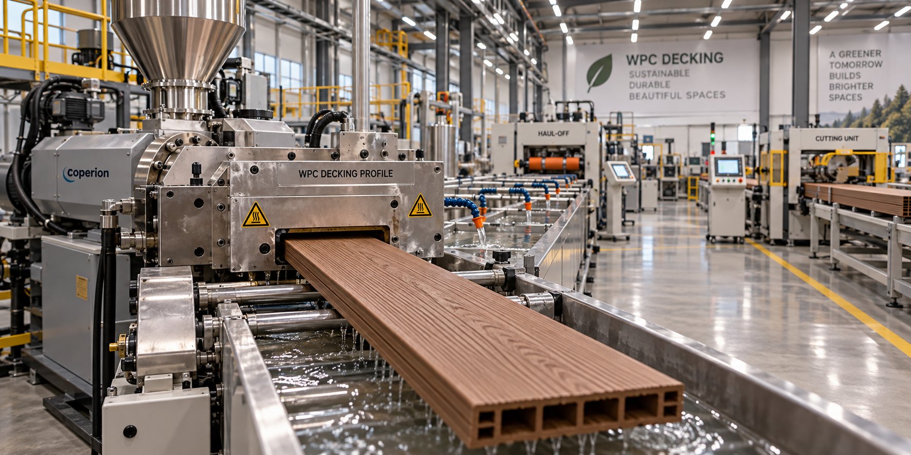
WPC Decking Extrusion Line Decoded: From Raw Resin To Finished Board
Oct 23, 2026
Learn how a WPC decking extrusion line works — from raw material compounding and extruder selection to process parameters, troubleshooting defects, and line layout planning.
Read Article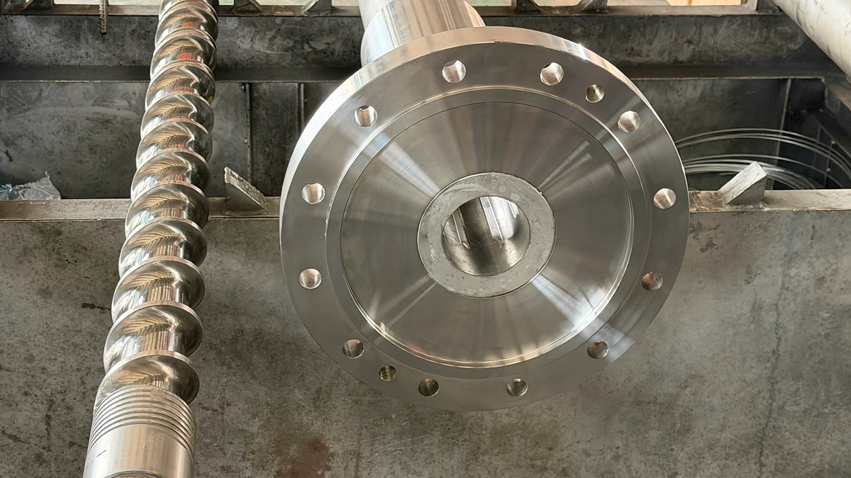
Single Screw Extruder Barrel Wear: Spot It, Measure It, Stop It
Oct 23, 2026
Learn how to spot, measure, and stop single screw extruder barrel wear. Zone-by-zone analysis, wear mechanisms, diagnostic symptoms, and repair vs. replace guidance.
Read ArticleLooking for something else?
Search by material, symptom or product and jump straight to the relevant page.
These are navigation suggestions based on keyword matching — not a quotation, not a delivery commitment, and not a substitute for engineering review. Final specification is confirmed by our engineers against your drawings and processed material.
Need help with screw barrel selection?
Share your machine model, processed material and application. Our team can help with pricing and technical support.