

What a Twin Screw Extruder Diagram Reveals About Your Extrusion Line
When you first look at a twin screw extruder diagram, you're seeing more than a technical drawing. You're looking at a complete roadmap of how raw material transforms into a finished product — every zone, every component, every transition captured in a single visual reference. For engineers specifying equipment, operators troubleshooting production issues, and procurement teams communicating requirements to suppliers, this diagram is the most important document attached to any twin screw extrusion system.
Yet most online resources treat these schematics as simple illustrations. They label a few parts, skip the details, and leave readers guessing about how each section actually functions. This guide takes a different approach. It walks you through every section of the diagram — from drive system to die head — with the kind of annotated, written breakdown that doesn't currently exist in any single resource.
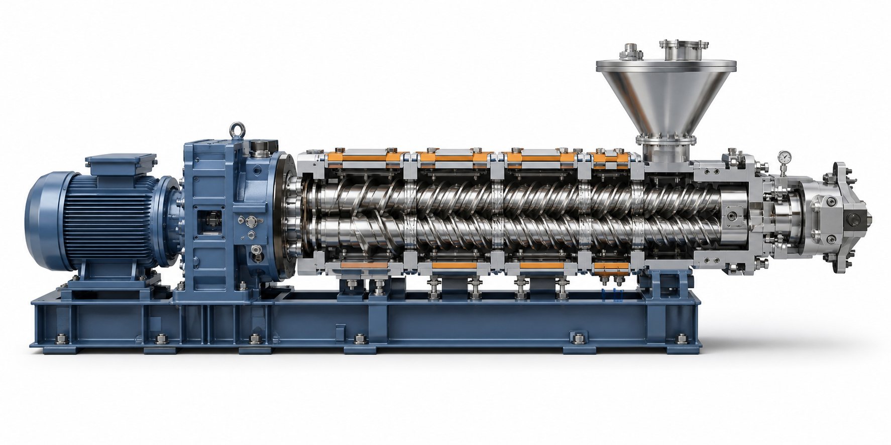
A proper twin screw extruder diagram maps the entire material transformation journey from raw feedstock input to finished product output.
What a Twin Screw Extruder Diagram Actually Shows
At its core, a twin screw extruder diagram is a labeled schematic that identifies every major assembly in the system. You'll find the electric motor and drive coupling at one end, followed by the gearbox (reducer), the segmented barrel with its individually heated and cooled zones, the twin screw elements running through the barrel bore, venting ports for devolatilization, and the die assembly at the discharge end. A literature review on twin screw extruder design describes the core components as the hopper, barrel, variable screw speed and temperature control, electrical motor, and replaceable dies. Side feeders, thermocouples, and pressure transducers also appear as secondary annotations, rounding out the picture of how every subsystem connects.
Why Diagram Literacy Matters for Extrusion Professionals
Reading a twin-screw extruder diagram correctly is a foundational skill in plastics processing. It allows your team to specify screw configurations with precision, map thermal zones to process requirements, and pinpoint exactly where a production problem originates. Imagine trying to describe a barrel modification to a manufacturer without referencing the zone numbers on the schematic — the conversation stalls immediately. Twin screw extrusion involves dozens of interdependent variables, and the diagram is the shared language that ties them all together. Whether you're designing a new compounding line or optimizing an existing recycling setup, fluency in reading these schematics directly impacts how quickly and accurately you can act.
Following Material Flow From Hopper to Die on the Diagram
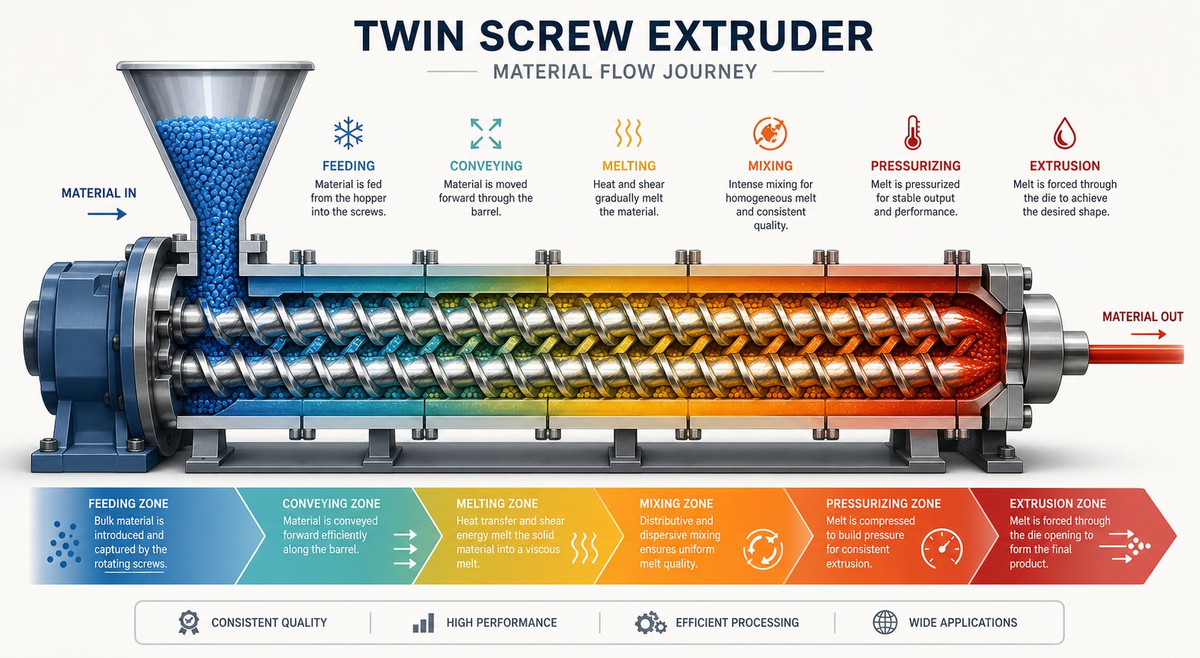
The best way to understand a twin screw extruder diagram is to stop looking at it as a static blueprint and start reading it as a story. Every labeled zone on the schematic represents a chapter in the life of a single polymer pellet — from the moment it drops into the feed hopper to the instant it emerges from the die as a finished product. Follow that pellet through the diagram, and every component suddenly has context.
Here is the sequential journey mapped across a typical twin screw extruder machine layout, station by station:
- Feed hopper and gravimetric feeder
- Feed throat and barrel entry zone
- Conveying zone with forward transport elements
- Melting and plasticating zone
- Mixing and kneading zone
- Venting and devolatilization port
- Pressure build-up zone
- Die head and exit
Each of these stations occupies a distinct position on the diagram, and recognizing them in sequence is the key to unlocking what the schematic is really telling you about the twin screw extrusion process.
Feed System and Material Entry on the Diagram
Look at the top of the barrel's first section on any standard diagram, and you'll find the feed hopper — a funnel-shaped vessel where raw material enters the system. Directly beneath or integrated with it sits the feeder mechanism, and this is where an important distinction shows up on the schematic. Volumetric feeders deliver material at a constant volume per unit of time, which works fine for consistent bulk-density materials. Gravimetric feeders, on the other hand, use a load cell to measure actual weight per unit of time, automatically compensating for density variations. On the diagram, you'll typically see the gravimetric feeder represented as a separate unit mounted above the feed throat, sometimes with a refill hopper or vacuum loader stacked on top of it.
But the main hopper isn't the only entry point. Many twin screw extruder machine configurations show side feeders — smaller, perpendicular barrel sections with their own twin screw conveyors — mounted partway down the barrel. These secondary entry points allow fillers, glass fibers, additives, or other downstream ingredients to be introduced after the polymer has already melted. On the diagram, they appear as lateral branches connected to specific barrel zones, and their placement is deliberate: adding abrasive fillers after the melting zone protects the upstream screw elements from excessive wear.
Melting, Mixing, and Discharge Zones Mapped
As your eye moves along the barrel from left to right on the diagram, you're tracking the same path the material follows during screw extrusion. The barrel is divided into individually numbered thermal zones — typically eight to twelve on production-scale machines — each with its own heating elements and cooling channels. Temperature setpoints increase progressively through the early zones, and the diagram often marks thermocouple locations indicating where sensors monitor the actual barrel wall temperature.
The transition from solid conveying to melt conveying is one of the most important boundaries on the schematic, even though it's rarely drawn with a bold line. In the first few barrel sections, forward-pitch conveying elements move solid pellets downstream. Then the diagram shows a shift to kneading blocks and mixing elements — this is where the combination of barrel heat and mechanical shear from the rotating screws transforms the solid material into a homogeneous melt. As Torontech's overview of twin screw extruder operation explains, the intermeshing screws generate shear forces that break down pellets and ensure thorough melting and dispersion of additives.
Further downstream, you'll notice the venting zone on the diagram — an open barrel section, sometimes connected to a vacuum pump, where moisture, trapped air, and volatile contaminants escape from the melt surface. This devolatilization step is critical for product quality. Past the vent, the screw extruder's final barrel sections contain tight-pitch conveying elements that build the pressure needed to push the melt through the die. This pressure build-up zone is where the material transitions from a low-pressure, partially filled state to a fully pressurized, continuous melt stream.
How the Die Section Connects to the Barrel
The rightmost section of the diagram — the discharge end — is where many schematics lose detail, but it's arguably where the process becomes most application-specific. Between the final barrel section and the die itself, you'll typically see an adapter zone. This adapter may include a breaker plate (a perforated metal disc that homogenizes flow and filters contaminants) and a screen pack. On some diagrams, a melt pressure transducer is indicated at this transition point, providing real-time feedback on discharge pressure.
The die itself changes shape depending on the product being manufactured. A compounding line diagram shows a strand die — a plate with multiple small circular openings that produce spaghetti-like strands of polymer, which are then cooled and chopped into pellets by a downstream pelletizer. A sheet extrusion diagram shows a wide, flat slot die designed to produce continuous flat sheet. Film dies, profile dies for custom cross-sections, and pipe dies each have distinctly different geometries, and recognizing the die type on a diagram immediately tells you what the entire line is designed to produce. Custom Profile's guide to extrusion die types categorizes these into pipe and tubing dies, profile extrusion dies, and co-extrusion dies for multilayered materials — each requiring different adapter configurations to bridge the barrel's circular outlet to the die's final shape.
This material-flow perspective turns every labeled component on the diagram into a functional checkpoint. And the deeper you look, the more you realize that the story doesn't just flow left to right — it depends heavily on what's driving the screws in the first place.
The Drive System Section of the Twin-Screw Extruder Diagram
Every barrel zone, every kneading block, and every milligram of throughput depends on what sits at the far left of the diagram — the drive system. It's the section most readers glance past on their way to the screws and barrel, yet it determines how much torque reaches the process, how fast the screws can turn, and ultimately how much product the line can produce. On a parallel twin screw extruder, the drive train typically accounts for a significant share of the machine's total capital cost, and for good reason: it's doing one of the hardest jobs in industrial power transmission.
The drive system on a standard twin screw extruder diagram consists of four primary components arranged in a linear sequence: the electric motor, a flexible or rigid coupling, the gearbox (also called a reducer or torque distribution box), and the thrust bearing assembly. Each one appears as a distinct block on the schematic, and understanding their relationship is essential for anyone evaluating a double screw extruder machine or specifying a replacement drive package.
Motor and Gearbox Placement in the Diagram
Look at the leftmost element on the schematic, and you'll find the electric motor — the component that converts electrical energy into rotational motion. Motors on twin-screw extruder machines are typically AC variable-frequency drives, allowing operators to adjust screw speed across a wide range. On the diagram, the motor is drawn as the largest single block in the drive section, often with a power rating (in kW) noted alongside it.
Moving to the right, a coupling connects the motor output shaft to the gearbox input shaft. This coupling absorbs minor misalignment and dampens vibration, protecting both the motor bearings and the gearbox gears. It appears on the diagram as a short connecting element — easy to overlook, but critical for mechanical longevity.
The gearbox itself is where things get interesting. Its job sounds straightforward — reduce the motor's high rotational speed to the lower speed the screws need while multiplying torque proportionally. But in a twin screw extruder, the gearbox must also split that torque evenly between two parallel output shafts while maintaining a precise centerline distance between them. Any deviation in that centerline distance and the intermeshing screws collide, damaging both the elements and the barrel bore. As Xinda's analysis of twin screw transmission systems explains, the torque distribution box is so central to extruder evolution that the industry's technical progress is often marked by successive generations of gearbox design.
Two dominant gearbox architectures appear across the industry. The parallel three-axis gear structure distributes power to two output shafts, but one shaft (the B-axis) is constrained by the tight centerline distance, limiting the gear size and therefore the torque capacity. The more advanced double-sided symmetrical drive structure solves this by feeding the B-axis from two sets of gears — upper and lower — so the radial forces cancel each other out and each gear set carries only half the load. This results in a pure torque output with no bending stress on the constrained shaft, dramatically extending service life.
Engineers evaluating a twin screw extruder diagram will often reference a key performance metric alongside the gearbox specifications: specific torque, expressed as Md/a3 (torque per unit of centerline distance cubed, measured in Nm/cm3). This single number tells you how much torque the gearbox can deliver relative to the geometric constraints of fitting two screws close together. Modern high-performance machines deliver torque densities of 18 Nm/cm3, representing roughly a 30% increase over previous-generation designs and enabling the processing of highly filled, high-viscosity materials that were previously torque-limited.
Thrust Bearings and Torque Distribution Explained
Torque isn't the only force the drive system must handle. As material melts and builds pressure against the die, it pushes the screws backward — toward the gearbox — with substantial axial force. Thrust bearings absorb this load, and on the diagram, they're typically indicated between the gearbox output shafts and the barrel entry point. You might see them drawn as a separate block or integrated within the gearbox housing, depending on the machine design.
The magnitude of these axial forces is considerable. In twin screw extruders, back pressure forces can range from approximately 2.5 kN on small laboratory machines to 3,400 kN on large production units. Thrust bearing capacity often limits gearbox life before the gear train itself wears out — an undersized thrust bearing fails through fatigue even when the gears are still performing well. The theoretical calculation life of extruder thrust bearings generally targets around 12,000 hours under normal operating conditions, though advanced symmetrical-drive gearboxes can extend this substantially by eliminating radial loads on the constrained shaft.
When you encounter a drive system specification table alongside a twin screw extruder diagram, you'll typically see several parameters listed together. Here's what each one means:
| Drive System Parameter | What It Represents | Why It Matters |
|---|---|---|
| Specific Torque (Md/a3) | Torque capacity normalized by the cube of the screw centerline distance, expressed in Nm/cm3 | Determines the maximum processing intensity the extruder can handle — higher values enable more demanding materials and higher fill levels |
| Screw Speed Range | The minimum and maximum rotational speed of the screws, expressed in rpm | Defines the operating window for shear rate and throughput; wider ranges offer more process flexibility |
| Motor Power | Rated continuous output of the electric motor, expressed in kW | Sets the upper limit of energy available for melting, mixing, and conveying; must be matched to gearbox torque capacity |
| Gear Ratio | The ratio of motor input speed to screw output speed | Determines how much the gearbox multiplies torque while reducing speed; higher ratios yield more torque at lower screw speeds |
A practical guideline when reviewing these specifications: plan to operate at roughly 80% of the continuous torque rating and 80% of maximum speed. This margin accounts for process variations, cold-start torque spikes (which can exceed steady-state values by 20-40%), and the inevitable fluctuations that come with real-world production. Treating the peak torque number on the spec sheet as the working capacity is one of the most common sizing mistakes — and the thrust bearings pay the price first.
The drive system may occupy only a small portion of the overall diagram, but it sets the ceiling for everything downstream. And directly to its right, where the gearbox output shafts enter the first barrel section, the story of the barrel zones and their thermal architecture begins.
Barrel Zones, Heating Jackets, and Venting Ports on the Diagram
Shift your attention to the center of any twin screw extruder diagram — the barrel — and you're looking at the largest, most segmented, and arguably most functionally dense portion of the entire schematic. Unlike the drive system, which is a handful of discrete blocks, the barrel section stretches across the majority of the drawing as a long, modular chain of individually numbered segments. Each segment serves a distinct thermal and mechanical role, and understanding how they're labeled, heated, cooled, and modified is what separates a casual glance at the diagram from a genuine engineering read.
A production-scale twin screw barrel is not a single cylinder. It's composed of multiple modular sections — typically eight to twelve on full-size machines — that bolt together end to end. As Plastics Technology's guide to barrel layout explains, the twin screw extruder can be viewed as a series of unit operations that can be arranged as needed to optimize the process. Segmented barrels provide a flexibility not seen in other polymer processes, allowing process engineers to address solids conveying, melting, mixing, venting, liquid injection, and pumping — all within the same machine frame. Each barrel section is typically four, five, or six screw diameters long, and every one of them carries independent heating and cooling hardware.
Barrel Zone Numbering and Thermal Control on the Diagram
When you look at the barrel on a twin screw extruder diagram, you'll notice each section is labeled with a zone number — Barrel 1, Barrel 2, Barrel 3, and so on, progressing from the feed end toward the die. These aren't arbitrary labels. Each zone number corresponds to an independently controlled thermal station, and the temperature setpoint assigned to each zone determines the thermal profile the material experiences as it moves through the machine.
Imagine a ten-zone barrel. The first zone may be set relatively cool to prevent premature softening that would block the feed throat. The middle zones ramp up to promote melting and plasticization. The final zones may hold steady or even decrease slightly to prevent thermal degradation before the melt reaches the die. This graduated profile is the thermal fingerprint of the process, and every zone on the diagram represents a point where that fingerprint can be adjusted.
How do the zones achieve this level of control? Look closely at the diagram annotations around each barrel section. You'll find two systems working in opposition:
- Heating elements: Most twin screw barrel sections use electric cartridge heaters inserted directly into bored channels within the barrel wall. Some designs use external band heaters clamped around the barrel surface. The diagram may indicate heater wattage or simply show heating zones with color coding.
- Cooling channels: Drilled passages within the barrel wall circulate water or oil to remove excess heat. During high-shear mixing, the screws can generate more frictional heat than the process needs, and cooling channels pull that surplus energy out to maintain the target temperature.
Thermocouple probes — small temperature sensors inserted into the barrel wall near the bore surface — appear on many diagrams as small dots or lines at each zone boundary. These probes feed real-time temperature data back to the control system, closing the loop between the setpoint you program and the actual barrel wall temperature. The closed barrel section illustration from Plastics Technology shows exactly this arrangement: heating elements and cooling channels working in tandem within the same barrel segment.
Here's a practical detail many diagrams don't spell out: open barrel sections — those used for feeding or venting — have fewer heaters and cooling channels than closed sections because the opening physically removes material from which heating or cooling hardware would otherwise be installed. This means thermal control is inherently weaker at feed and vent zones, a fact that matters when you're troubleshooting temperature deviations.
Venting Ports and Side Feeders as Barrel Modifications
Not every barrel section on the diagram looks the same. Some have openings on top, some have perpendicular branches on the side, and these modifications are among the most important features to identify when reading the schematic.
Venting ports appear as open barrel sections — typically in the latter half of the barrel — where the top of the figure-eight bore is exposed to the atmosphere or connected to a vacuum pump. Their purpose is devolatilization: removing moisture, trapped air, and volatile byproducts from the polymer melt before it reaches the die. As Adam Dreiblatt of CPM Century Extrusion notes, stable vent operation requires a low degree of fill within the screws in the vent area and a melt seal — a section of fully filled screw — upstream of the vent opening. Most compounding processes include both atmospheric vents (commonly near side feeders to release entrained air) and at least one vacuum vent near the discharge end for final degassing.
Side-stuffer barrels appear on the diagram as perpendicular entry points, each with its own twin screw feeder bore intersecting the main barrel bore. These are the doorways for downstream addition of fillers, glass fibers, pigments, or other additives. A more compact variation is the back-vent combi-barrel, which combines a side-feed port with a small upstream atmospheric vent in a single barrel section — a design that saves one barrel position on the overall layout.
Every opening in the barrel — whether for venting or side feeding — removes structural material from the barrel wall. This affects rigidity and thermal uniformity. When a vent barrel or side-feed barrel needs replacement, the new section must match the original configuration precisely: same bore geometry, same opening dimensions, same heater and cooling channel layout. Installing a closed barrel where a vent barrel belongs, or a standard vent barrel where a combi-barrel was specified, disrupts the entire process architecture mapped in the diagram.
Why Barrel and Screw Barrel Quality Impacts Every Zone
Every zone on the diagram tells you something else if you know where to look: where the barrel is wearing out. Wear patterns in a plastic twin screw extruder correspond directly to the thermal and mechanical stress mapped in the schematic. The kneading zones — where shear forces peak and abrasive fillers are being dispersed — experience the highest wear rates. Vent zones, where melt pressure drops and the screws are only partially filled, tend to wear more slowly. Feed zones fall somewhere in between, especially when processing abrasive raw materials.
The barrel material itself is the first line of defense. Production barrels are typically manufactured from nitrided steel or bimetallic-lined sections, with wear-resistant alloys applied to the bore surface in zones that handle the most demanding processing conditions. As Cowell Extrusion highlights, advanced HIP (hot isostatic pressing) materials can deliver wear resistance several times greater than common metals, significantly reducing the frequency of barrel replacements and minimizing unplanned downtime.
This is where the twin screw extruder diagram transitions from a design reference into a maintenance planning tool. By mapping observed wear to the specific barrel zones on the schematic, maintenance teams can predict which segments will need replacement next and source the correct twin screw and barrel assemblies before a failure forces a shutdown. For extrusion manufacturers, recycling plants, and technical teams sourcing replacement barrels and screw barrel components matched to specific zones, NANHAIYA's screw barrel support for plastic extruder machines covers configurations across pipe, profile, sheet, pelletizing, recycling, and general processing lines — providing a practical sourcing path for the barrel segments identified on your twin screw extruder plastic system diagram.
Barrel zone architecture defines the thermal and mechanical environment the material encounters at every point in its journey. But the barrel is only half the story inside that figure-eight bore. What happens to the material depends equally on the screw elements rotating within it — and those elements follow their own distinct visual language on configuration diagrams.
Screw Element Types and How They Appear in Configuration Diagrams
The barrel defines the thermal environment. The screw elements define what actually happens to the material inside it. Every twin screw extruder diagram includes — or should include — a screw configuration layout that maps individual elements along the length of the barrel bore. Yet this is precisely where most written explanations fall short: they mention "screw elements" as a category but never break down what each type looks like on the diagram, what it does to the polymer, or where it belongs in the sequence. For anyone operating or specifying a compounding twin screw extruder, this gap is a serious problem — because the screw configuration is the single most influential variable in determining product quality.
A twin screw compounding extruder screw is not a single machined piece. It's a modular assembly of discrete elements slid onto a splined shaft in a deliberate sequence. As NC State Extension's screw design publication explains, configuring a screw profile is a blend of art and science — no gold standard exists because every material exhibits unique flow properties influenced by temperature, shear rate, and extruder geometry. The arrangement of elements on the shaft depends entirely on the process and the material being run.
Forward Conveying Elements and Their Diagram Symbols
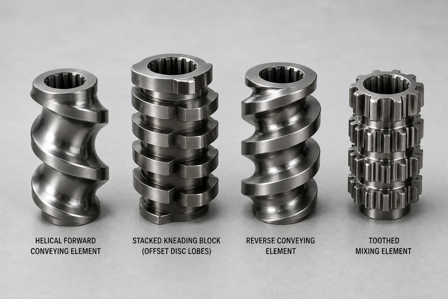
Conveying elements are the workhorses of any screw layout. They feature helical flights wrapped around a cylindrical root, and their job is straightforward: move material downstream from the feed end toward the die. On a configuration diagram, they appear as angled parallel lines — think of them as simplified representations of the spiral flight path. The steeper the angle, the larger the pitch.
Pitch is the defining characteristic here. It represents the axial distance one flight travels in a single rotation. A large-pitch conveying element — roughly 1.5 to 2 times the screw diameter — moves material forward quickly, resulting in low fill levels in that section of the barrel. You'll find these at the feed zone, where the priority is pulling material in from the hopper efficiently, and at vent zones, where low fill is essential to expose melt surface area for devolatilization. A small-pitch element — around 0.25 to 0.75 times the diameter — slows the material down, increasing the degree of fill and building pressure. These tight-pitch elements typically appear near the discharge end, where the screw needs to generate enough pressure to push the melt through the die.
Conveying elements also vary by the number of flights, or "threads." According to Cowin Extrusion's screw configuration guide, double-flighted (two-start) elements are the standard for co-rotating compounding extruder screws, offering a practical balance between conveying capacity and shear. Single-flighted elements have wider flights that minimize material leakage and maximize suction efficiency — useful at the feed throat. Triple-flighted elements generate the highest shear due to their shallow channel depth, making them suitable for melting and dispersion tasks rather than simple transport.
Kneading Blocks at 30, 60, and 90 Degree Stagger Angles
If conveying elements are about transport, kneading blocks are about transformation. These are the elements that melt, mix, and homogenize. On the diagram, they look distinctly different from conveying elements: instead of continuous helical flights, you'll see a series of individual disc-shaped lobes stacked together at offset angles. The stagger angle — the rotational offset between one disc and the next — is the single most important parameter determining what a kneading block does to the material.
Here's where a critical distinction comes in that many operators overlook: the difference between distributive and dispersive mixing. Plastics Technology's mixing configuration guide defines these clearly. Distributive mixing evenly spreads an additive throughout the polymer matrix without necessarily breaking down particle size — imagine stirring cream into coffee. Dispersive mixing breaks apart agglomerates and clumps by applying intense shear stress — imagine crushing sugar lumps before dissolving them. Most compounding operations need both, but the ratio depends entirely on the material.
The stagger angle controls which type of mixing dominates:
- 30-degree kneading blocks provide gentle distributive mixing with strong forward conveying action. The shallow offset between discs means material slides through relatively easily, getting stirred and reoriented but not subjected to intense shear. These are your "light touch" mixing elements.
- 60-degree kneading blocks deliver a moderate combination of both dispersive and distributive mixing. Forward conveying capability decreases compared to 30-degree blocks, which means material spends more time in the mixing zone and experiences higher shear forces. They sit in the middle ground — aggressive enough to break down most agglomerates, gentle enough to avoid excessive melt temperature rise.
- 90-degree kneading blocks are neutral — they provide zero forward conveying action. Material does not advance due to screw rotation alone; it only moves because upstream elements push it through. This creates maximum fill, maximum residence time, and maximum dispersive mixing intensity. As the Cowin Extrusion reference notes, 90-degree blocks produce 100% filling with very strong mixing capability but no conveying.
Disc width matters too. Wide kneading discs plow through the polymer, creating a pool of melt in front of each disc and smearing it through the gap — this promotes dispersive mixing. Narrow discs, by contrast, slice through the melt in a scissoring action that divides and recombines the material, promoting distribution. As Kenneth Russell of Optimized Compounds explains in Plastics Technology, the first consideration in screw design regarding mixing is disc width: wide discs for dispersion, narrow discs for distribution.
Reverse Elements and Mixing Elements in the Configuration
Not everything on the screw moves material forward. Reverse conveying elements — also called left-handed elements — have helical flights with the opposite hand of rotation compared to standard forward elements. On the diagram, they're often marked with an "L" designation (for left-handed rotation) or drawn with flight angles tilted in the opposite direction.
Their purpose is to push material backward against the main flow direction. Sounds counterproductive? It's actually one of the most powerful tools in screw design. A reverse element placed after a kneading zone forces material to accumulate upstream, creating a fully filled melt seal. This seal is essential for two reasons: it isolates the venting zone downstream (preventing air from being sucked backward through the melt) and it ensures the kneading blocks upstream operate at high fill levels where mixing efficiency is greatest. As the NC State publication describes, reverse kneading blocks push material backward, ensuring maximum restriction in forward flow and thus creating maximum shear.
Beyond kneading blocks and reverse elements, specialized mixing elements round out the configuration toolkit. Toothed mixing elements — designated with a "Z" prefix in common nomenclature — feature rows of interlocking teeth rather than continuous flights or stacked discs. They provide effective distributive mixing with minimal pressure drop and near-zero dispersive action. This makes them ideal for blending temperature-sensitive additives or incorporating fragile reinforcements like glass fibers that would be damaged by the intense shear of kneading blocks.
The table below organizes the primary element types you'll encounter on any twin screw extruder diagram, along with their visual characteristics, functions, and typical positions in the screw layout:
| Element Type | Diagram Symbol Description | Primary Function | Typical Placement Zone |
|---|---|---|---|
| Forward Conveying (large pitch) | Angled parallel lines with wide spacing; often labeled with pitch and length values (e.g., SE-40/40 R) | Rapid material transport at low fill; maximizes intake and venting efficiency | Feed zone; vent zone |
| Forward Conveying (small pitch) | Angled parallel lines with narrow spacing; shorter pitch designation | Pressure build-up; increased fill and residence time | Metering/discharge zone before the die |
| Kneading Block (30-degree stagger) | Stacked disc profiles offset at shallow angles; forward conveying direction indicated | Gentle distributive mixing with forward conveying action | Initial mixing section; downstream blending after side feeding |
| Kneading Block (60-degree stagger) | Stacked disc profiles offset at moderate angles | Balanced dispersive and distributive mixing; reduced forward conveyance | Primary melting and mixing zone |
| Kneading Block (90-degree neutral) | Stacked disc profiles offset at right angles; no conveying direction indicated | Maximum dispersive mixing; zero forward conveying; 100% fill | Intensive mixing zone; melt seal creation upstream of vents |
| Reverse Conveying Element | Angled parallel lines tilted opposite to forward elements; labeled with "L" (left-hand) designation | Creates backpressure and melt seal; restricts forward flow | Immediately downstream of kneading zones; upstream of vent openings |
| Toothed Mixing Element | Rows of interlocking tooth profiles; often labeled with tooth count and row number (e.g., Z 8/3/20) | Distributive mixing with minimal shear and pressure drop | Downstream blending zone; after side-fed fillers or fibers |
One nuance worth emphasizing: most experienced screw designers end their mixing sections with a neutral or reverse element rather than trailing off with forward-conveying kneading blocks. The reasoning, as Russell notes, is that mixing sections operate more efficiently and more gently at higher fill levels. A mixing section composed entirely of forward-conveying kneading blocks tends to run partially empty — and partially empty kneading blocks can "whip" the polymer, raising melt temperature and damaging the aspect ratio of fiber reinforcements. Balance between forward drive and flow restriction is the key.
Every element in the table above is a building block. Strung together in sequence, they form a complete screw configuration — and that configuration follows its own shorthand notation system, a visual language that experienced extrusion professionals read as fluently as sheet music.
Cross-Sectional Geometry of Intermeshing Twin Screws
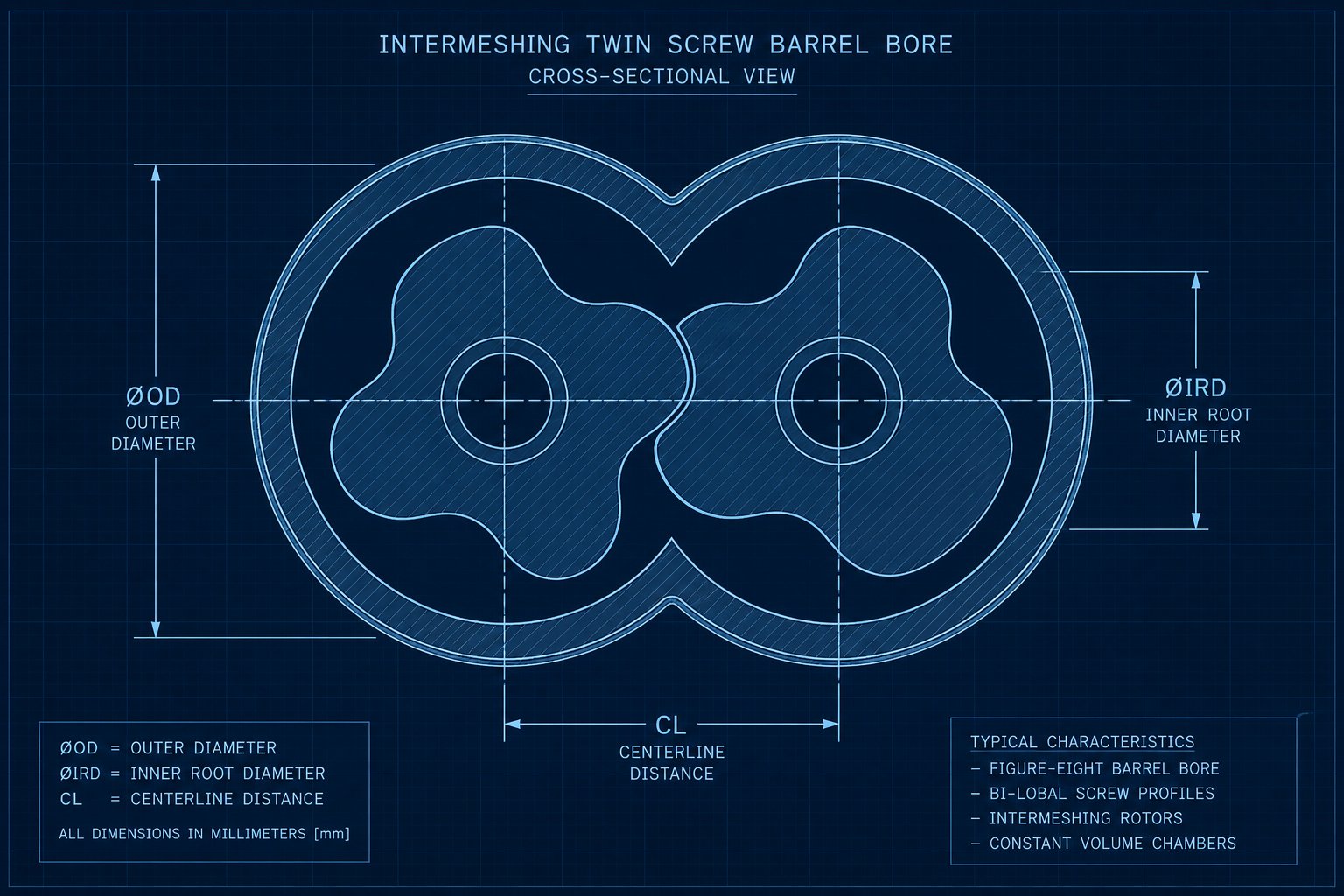
Screw element types and their sequence along the barrel tell you what happens to the material. But to understand how those elements interact with each other and with the barrel wall, you need a different view entirely. Imagine slicing straight through the barrel perpendicular to the screw axis, the way you'd cut through a loaf of bread. The cross section that appears is one of the most information-dense views on any twin screw extruder diagram — and one of the least explained.
Understanding the Figure-Eight Bore Cross Section
When you look at that cross-sectional slice, you don't see two separate round holes. You see a figure-eight shape — two overlapping circles merged at the center, with the barrel wall forming a continuous boundary around both. This figure-eight bore is the defining geometric feature of any intermeshing extruder twin screw design. The degree of overlap between the two circular bores determines how deeply the flights of one screw reach into the channel of the other, which directly controls the self-wiping action that keeps polymer from stagnating on screw surfaces.
As Delvar et al. detail in their literature review on twin screw extruder geometry, the cross-section of a self-wiping co-rotating extruder is defined by the relationship between the screw radius, the centerline distance between the two shafts, and the intermeshing angle. One screw must wipe its counterpart regardless of rotational position, and this kinematic constraint locks the geometric proportions together — you can't change one dimension without affecting the others.
Several key geometric terms appear on cross-sectional diagrams, and each carries real engineering significance:
- Outer screw diameter (Do): The maximum diameter swept by the screw flight tips. This is the dimension that matches the barrel bore diameter and defines the screw "size" quoted in machine specifications.
- Inner screw diameter or root diameter (Di): The diameter of the screw at its deepest channel — the core from which the flights extend outward. The difference between Do and Di determines the flight depth, which is the available channel space where material actually resides.
- Centerline distance (a): The fixed distance between the rotational axes of the two screws. This dimension is locked by the gearbox design and must remain precise — even minor deviations cause the intermeshing twin screws to contact each other, resulting in rapid wear or catastrophic damage.
- Flight depth: Calculated as (Do - Di) / 2, this is the radial depth of the channel between the flight tip and the screw root. Deeper channels hold more material per revolution; shallower channels impose higher shear rates on the melt.
- Channel width: The circumferential distance between adjacent flight flanks. Together with flight depth, it defines the cross-sectional area available for material processing at any point along the screw.
These dimensions aren't independent. The self-wiping constraint means that for a double screw extruder with two-lobe screw profiles (the most common configuration), the centerline distance, outer diameter, and inner diameter are mathematically linked. Change the Do/Di ratio, and the centerline distance must shift accordingly — or the screws stop wiping cleanly.
L/D Ratio, Do/Di Ratio, and Free Volume Visualized
Step back from the cross section and consider the full barrel length, and you'll encounter the single most frequently quoted specification on any twin screw extruder diagram: the L/D ratio. This number — barrel length divided by screw outer diameter — tells you how long the processing path is relative to the screw size. A higher L/D ratio means the material spends more time inside the machine, passes through more functional zones, and undergoes more processing steps before reaching the die.
In modern twin screw extruders, L/D ratios typically range from 20:1 to 48:1. Shorter ratios suit applications requiring high shear mixing with limited residence time — think color masterbatch production where thermal sensitivity demands speed. Longer ratios accommodate processes that need extended residence time, such as devolatilization, reactive extrusion, or heavily filled compound processing where multiple side feeders and vacuum vents must all fit along the barrel length.
The Do/Di ratio, by contrast, is a cross-sectional parameter that determines how much room there is inside the screw channels. A larger Do/Di ratio means deeper flights and more free volume per unit of barrel length — more space for material to occupy. This is critical for processes that require high throughput or handle bulky, low-density feedstocks like powders and flakes. A smaller Do/Di ratio yields shallower channels, higher shear rates, and greater torque capacity for a given screw diameter, making it better suited for processing high-viscosity materials that demand intense mechanical energy input.
Here's a consolidated reference list of the geometric parameters you'll encounter alongside any twin screw extruder diagram:
- L/D ratio (Length-to-Diameter ratio): Total barrel length divided by screw outer diameter. Determines the number of processing zones that can fit along the barrel and directly influences residence time, mixing intensity, and process versatility.
- Do/Di ratio (Outer-to-Inner Diameter ratio): Outer screw diameter divided by root diameter. Controls the free volume available in the screw channels — higher ratios mean more volume per unit length, lower ratios mean higher torque density and shear capability.
- Specific torque (Md/a3): Maximum allowable torque per screw normalized by the cube of the centerline distance, expressed in Nm/cm3. This is the benchmark for comparing drive system capability across different machine sizes.
- Free volume per L/D: The total open channel volume available for material within one L/D unit of barrel length, typically expressed in cm3/D. Combines the effects of Do/Di ratio and screw geometry into a single throughput-relevant number.
- Centerline distance (a): The fixed spacing between screw shaft axes, defined by the gearbox output geometry. Constrains the maximum outer diameter and intermeshing depth, and appears in the specific torque formula as the normalizing dimension.
These parameters don't exist in isolation — they form an interlocking system. Increasing free volume by raising the Do/Di ratio reduces the shaft core diameter, which limits the torque that can be transmitted through the splined connection. Increasing L/D adds process flexibility but requires more barrel sections, more heating zones, and a longer machine footprint. Every specification on the diagram reflects a design trade-off, and the cross-sectional geometry is where those trade-offs become most visible.
Knowing what these dimensions mean is one thing. Reading them off a real screw configuration chart — the kind that arrives with a machine or accompanies a screw design proposal — requires a different skill: decoding the standardized shorthand notation that the extrusion industry uses to communicate screw layouts.
How to Read Twin Screw Configuration Shorthand Notation
A screw configuration chart is the blueprint-within-the-blueprint. It's a linear diagram that lays out every screw element in sequence from the feed end to the discharge end, with each element identified by a compact alphanumeric code. Engineers at twinscrew equipment manufacturers, compounding plants, and research labs all rely on this notation to specify, replicate, and modify screw designs — yet it's almost never explained in plain language. If you've ever stared at a row of codes like "SE 40/40 R" or "KB 60/6/60" and wondered what you were reading, this section is for you.
Decoding the Standard Screw Configuration Chart
Every code on a screw configuration chart follows a predictable structure: a prefix identifying the element type, followed by numbers that describe its key dimensions. The specific format varies slightly between twin-screw extruder manufacturers, but the underlying logic is consistent across the industry.
For conveying elements, the code typically reads as a prefix plus two numbers separated by a slash. Using the notation system documented by NC State Extension's screw design publication, a conveying element labeled SE - 30/30 R breaks down like this:
- SE — Screw Element (identifies the element type as a conveying element)
- 30 (first number) — Flight pitch in millimeters, representing the axial distance one flight covers per revolution
- 30 (second number) — Length of the element in millimeters
- R — Direction of rotation; R means right-handed (forward conveying), while L means left-handed (reverse conveying)
So an SE - 30/30 R is a 30-mm-long forward conveying element with a 30-mm pitch. Swap that trailing letter to L — SE - 30/30 L — and you've got a reverse element of the same dimensions, designed to push material backward and create a melt seal.
For kneading blocks, the notation adds a third number. As Granuwel's melting section configuration guide explains, the shorthand follows the format KB XX/YY/ZZ:
- KB — Kneading Block
- XX — Stagger angle between discs (e.g., 30, 45, 60, or 90 degrees)
- YY — Number of individual discs in the block
- ZZ — Total length of the element in millimeters
A code reading KB 60/6/60 tells you this is a kneading block with six discs stacked at 60-degree offsets, measuring 60 mm in overall length. Each disc in that block is therefore 10 mm wide — a detail you calculate by dividing the total length by the disc count. Wider discs apply more energy to the polymer, while narrower discs slice through it more gently.
Some manufacturers use slightly different prefixes. The NC State reference documents Brabender's system, where KP indicates a kneading block with half-width discs on each side, and KBW denotes blocks with full-width discs on both sides. A KP - 45/5/20 R is a forward-conveying kneading block with five half-width discs at 45-degree offsets, 20 mm long. The R at the end confirms forward conveying; change it to L, and the element becomes a reverse kneading block that pushes material upstream.
For toothed mixing elements, the format shifts again. A code like Z 8/3/20 means:
- Z — Toothed mixing element (from the German "Zahn," meaning tooth)
- 8 — Number of teeth per row
- 3 — Number of tooth rows
- 20 — Element length in millimeters
You'll notice there's no R or L suffix here. Toothed mixing elements are generally conveying-neutral — they redistribute material without actively pumping it forward or backward. That's precisely why they're chosen for gentle blending tasks where preserving fiber length or avoiding thermal degradation matters.
Mapping Elements to Barrel Zones on the Configuration Diagram
A screw configuration chart isn't just a list of element codes. It's a spatial map. On a typical layout, each element's position is aligned to the barrel section numbers directly above or below it. Imagine a horizontal bar divided into labeled segments — Barrel 1, Barrel 2, Barrel 3, and so on — with a corresponding row of element codes beneath, placed in the exact positions those elements occupy within each barrel section.
This alignment is what makes the configuration chart genuinely powerful. It lets you see which elements sit inside which thermal zone. You can instantly identify, for example, that a sequence of KB 60/5/40 R blocks falls within Barrel 4 — which is set to a specific temperature — while a reverse element SE 20/20 L sits at the boundary between Barrel 5 and Barrel 6, acting as the melt seal upstream of a vacuum vent in Barrel 7. The chart ties mechanical action to thermal control, zone by zone.
This element-to-barrel mapping is essential for every major design decision in twin-screw extruders. Designing a melting zone means selecting the right kneading block sequence and placing it within barrel sections set to the correct temperature ramp. Building a venting zone means ensuring that low-pitch forward conveying elements occupy the barrel section under the vent opening, keeping fill levels low enough to expose melt surface for degassing. A pressure-building zone requires tight-pitch conveying elements in the final barrel sections, and the barrel temperatures there may need to decrease slightly to raise melt viscosity and improve pumping efficiency.
When troubleshooting, this mapping becomes a diagnostic roadmap. If unmelted particles appear in the finished product, you trace the melting zone on the chart — identify the kneading block sequence and the barrel temperatures in those zones — and evaluate whether more aggressive elements, higher zone temperatures, or both are needed. If degradation appears, you check whether the combination of 90-degree kneading blocks and high barrel temperatures in a specific zone is generating excessive thermal history. Every symptom maps back to a specific intersection of screw element and barrel zone on the chart.
Mastering screw configuration shorthand is the single most practical skill for anyone who needs to specify, modify, or troubleshoot a twin screw extrusion process.
The notation system itself is universal in concept, even when the exact prefixes differ between screw extruders from different manufacturers. Learn the logic once — element type, dimensional parameters, rotation direction — and you can read any configuration chart in the industry. It's the closest thing the extrusion world has to a common technical language.
With this notation decoded, a natural question emerges: how does the configuration chart change depending on whether the twin screws rotate in the same direction or in opposite directions? The answer reshapes not just the element codes but the entire material flow path — and the diagram looks fundamentally different for each case.
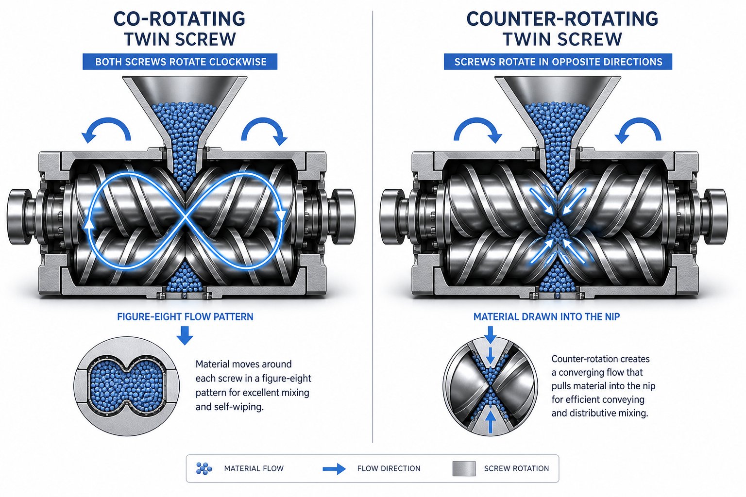
Co-Rotating vs Counter-Rotating Configurations Compared
The screw configuration shorthand tells you what elements are on the shaft and where they sit. But it assumes you already know something more fundamental: which direction the screws are turning — and whether they're both turning the same way. This single variable — rotation direction — changes the material flow path, the intermeshing geometry, the mixing mechanism, and ultimately how the entire twin screw extruder diagram reads. Yet side-by-side visual and written comparisons of co rotating and counter rotating twin screw extruder configurations are remarkably hard to find. Here's what each one actually looks like on the schematic, and why the differences matter.
Co-Rotating Intermeshing Configuration Diagrams
In a co rotating twin screw extruder, both screws turn in the same direction — typically both clockwise when viewed from the drive end. On cross-sectional diagrams, you'll notice the two screw profiles appear as mirror images that "hand off" material at the intermeshing zone. As one flight pushes material toward the top of the barrel, the adjacent screw's flight catches it and sweeps it around the opposite bore. The result is a continuous figure-eight flow path — sometimes described as an infinity-shaped or spiral pattern — where polymer travels alternately around one screw, then the other.
This flow path creates a defining feature visible even in simplified schematics: self-wiping action. Because the flights of one screw continuously scrape the surface of the other, material stagnation is suppressed and the residence time distribution stays narrow. As Technovel's technical analysis explains, the self-wiping behavior plays a particularly important role during reactive extrusion and when processing materials sensitive to thermal history, because it prevents localized overheating from prolonged wall contact.
On a full-length layout diagram, the co-rotating configuration is recognizable by its modular element sequence. The screw shaft accommodates freely interchangeable conveying elements, kneading blocks, and mixing elements — the same components covered in the previous section. This modularity is why co-rotating machines dominate compounding applications. Typical uses span inorganic and organic filler compounding, polymer alloy and blend production, nanocomposite processing, and reactive extrusion involving in-line polymerization or compatibilization. The intense shear fields generated between the screws and between screw and barrel, combined with the elongational flow from kneading blocks, give co-rotating extruders exceptional control over filler dispersion and phase morphology.
Co-Rotating and Counter-Rotating: Intermeshing and Conical Variations
Flip one screw's rotation direction, and the entire internal flow field changes. In a counter-rotating twin screw extruder, the screws turn in opposite directions. At the intermeshing region, material is drawn inward between the two screws rather than swept around them, creating what's often described as a calender-like nip. Picture two rollers pulling fabric between them — the compressive and elongational deformation at that nip disperses material under gentler conditions than the high-shear co-rotating approach.
On cross-sectional diagrams, the difference is immediately visible. Instead of the figure-eight flow pattern, counter-rotating screws create enclosed C-shaped chambers between the flights, producing a positive-displacement conveying mechanism that moves material forward even at low screw speeds. As documented by industry references, this C-shaped flow chamber facilitates stable transport with less dependence on material viscosity, which is why counter-rotating machines excel at processing thermally sensitive polymers like rigid PVC. The lower shear stress keeps melt temperatures down, preventing decomposition in materials with narrow processing windows.
A further visual departure appears in conical twin screw extruder diagrams. Where parallel configurations show two uniform-diameter screws running side by side through a constant-bore barrel, conical designs feature screws that taper from a large diameter at the feed end to a smaller diameter at the discharge end. On the diagram, the barrel bore follows this same taper, creating a geometry that looks dramatically different from anything discussed so far. This tapered profile creates a natural compression zone as material advances — the decreasing volume forces the polymer into progressively tighter space, enhancing melting efficiency and pressure generation. Conical designs also gain a practical advantage: the larger feed-end diameter provides more root area for robust shaft and bearing support, enabling high torque transmission in a compact machine footprint.
The comparison below consolidates these differences into a structured reference. When you encounter a twin screw extruder diagram, identifying which category it belongs to is the first step toward understanding everything else on the schematic:
| Characteristic | Co-Rotating (Parallel) | Counter-Rotating (Parallel) | Counter-Rotating (Conical) |
|---|---|---|---|
| Rotation Direction | Both screws rotate the same direction | Screws rotate in opposite directions | Screws rotate in opposite directions |
| Intermeshing Pattern | Fully intermeshing with self-wiping flight profiles | Fully or partially intermeshing with calender-like nip | Fully intermeshing along tapered bore |
| Material Flow Path | Figure-eight (infinity-shaped) path around both screws | C-shaped enclosed chambers between flights | C-shaped chambers with progressive compression |
| Self-Wiping Capability | Complete self-wiping; minimal dead zones | Limited self-wiping; material residence less uniform | Limited self-wiping; compression assists forward transport |
| Typical Applications | Compounding, reactive extrusion, polymer blends, nanocomposites | Rigid PVC pipes, sheets, and profiles; heat-sensitive materials | PVC profile and pipe extrusion; medium-capacity production lines |
| Diagram Appearance | Uniform-diameter parallel screws; modular element sequence along full barrel length | Uniform-diameter parallel screws; fewer modular element variations shown | Tapered screws and barrel bore; visually converging from feed to discharge end |
One detail worth noting: co-rotating diagrams almost always show a highly modular screw layout with multiple element types because the freely configurable design is central to how these machines are used. Counter-rotating diagrams, especially conical variants, tend to show fewer element transitions — the screw geometry itself is more purpose-built for specific forming applications rather than reconfigured job to job.
Rotation direction and screw geometry define the machine's core identity. But the same fundamental diagram framework — drive, barrel, screws, die — adapts further depending on what product the line is designed to make. A compounding setup, a recycling line, and a laboratory extruder all share the same schematic DNA, yet each looks noticeably different when you examine the details.
How Diagrams Change Across Different Extrusion Applications
A compounding line, a plastics recycling system, and a benchtop twin screw extruder in a university lab all share the same schematic skeleton — motor, gearbox, barrel, screws, die. Yet place their diagrams side by side, and the differences jump off the page. Feed openings shift in size and number. Venting ports multiply or disappear. Die configurations transform entirely. The base diagram is a template; the application fills in the details. Understanding how that template adapts to real production scenarios is what separates someone who can read a generic schematic from someone who can evaluate whether a specific line is designed correctly for its intended job.
Compounding and Pelletizing Line Diagrams
Compounding is the most common application for co-rotating twin screw plastic extruder systems, and the diagrams reflect it. When you look at a compounding line schematic, the first thing you'll notice is the sheer number of entry points along the barrel. Beyond the main feed hopper at Barrel 1, you'll typically see two or even three side feeders mounted at downstream barrel sections — each one introducing a different ingredient into the already-molten polymer. One side feeder might deliver calcium carbonate or talc filler. Another might introduce glass fiber reinforcement. A third could add color concentrate or flame retardant masterbatch.
Why not feed everything at once through the main hopper? Because abrasive fillers would destroy upstream screw elements during the melting phase, and fragile glass fibers would be shattered to useless dust by the kneading blocks needed to melt the base resin. Downstream feeding, clearly mapped on the diagram, solves both problems by introducing these materials after the polymer has already been plasticized.
The screw configuration section of a compounding diagram is equally busy. You'll see intensive kneading zones — often with 60-degree and 90-degree stagger kneading blocks — positioned immediately after each side feeder to disperse the incoming additive into the polymer matrix. Between these mixing zones, forward conveying elements transport the compound downstream. At least one atmospheric vent typically appears near each side feeder to release entrained air that arrives with the dry powder or pellet additives, and a vacuum vent further downstream handles final devolatilization before the die.
At the discharge end, the diagram departs significantly from other configurations. Instead of a profile or sheet die, compounding lines show a strand die — a plate with rows of small circular openings — connected to a water bath or cooling conveyor, followed by a strand pelletizer that chops the cooled strands into uniform pellets. Alternatively, you'll see an underwater pelletizing system where the screw extruder granulator head is mounted directly at the die face. In this setup, a spinning blade cuts the emerging melt strands into pellets inside a water chamber, and the pellets are carried away hydraulically. The diagram for an underwater pelletizing setup looks visibly different: there's no long cooling trough, and the cutting head appears as a compact unit bolted directly to the die plate.
Recycling and Devolatilization Extruder Diagrams
Recycling line diagrams tell a different story. The feedstock is not clean, uniform pellets — it's post-consumer flake, regrind, or agricultural film with inconsistent bulk density, unpredictable moisture levels, and a cocktail of volatile contaminants. Every one of those challenges leaves a visible mark on the schematic.
The feed section is the first giveaway. Recycling diagrams typically show an oversized feed opening — sometimes a cram feeder or force-fed hopper — to accommodate low-bulk-density materials like film scraps or bottle flake that would bridge and starve a standard gravimetric feeder. Some configurations replace the conventional top-mounted hopper entirely with a side-entry crammer that forces the irregularly shaped feedstock into the barrel mechanically.
Moving downstream, the melting zone on a recycling diagram tends to be more aggressive than a standard compounding layout. Tightly stacked kneading blocks and reverse elements appear earlier in the barrel because contaminated feedstock often contains mixed polymers, paper labels, and residual adhesives that require intense shearing to homogenize. As Rob Jerman explains in Plastics Technology, devolatilization is a mass-transfer process driven by superheating the volatile component and then exposing the melt to rapid decompression — and recycling applications lean heavily on this mechanism because the incoming material carries far more moisture, residual monomers, and degradation byproducts than virgin resin.
The most striking visual difference on recycling diagrams is the number of venting ports. Where a standard compounding schematic might show one atmospheric vent and one vacuum vent, recycling configurations often include two or even three vacuum vents spaced along the latter half of the barrel. Jerman provides a practical rule of thumb: each vent can reduce volatile concentration by roughly an order of magnitude. A triple-vented machine can take a heavily contaminated feed down to residual levels below 0.1%. On the diagram, each vent zone is separated by a melt seal — a reverse element or restrictive kneading block sequence that prevents vacuum from one vent zone from affecting its neighbors.
Between the final vent and the die, recycling diagrams frequently include a component rarely seen on compounding schematics: a melt filtration unit. This is a screen changer or continuous melt filter that removes solid contaminants — metal fragments, sand, paper fibers, wood particles — from the melt stream before it reaches the die. On the schematic, it appears as a separate housing mounted between the barrel flange and the die adapter.
Laboratory vs Production Scale Diagram Differences
Imagine shrinking a full production line to fit on a benchtop. The fundamental diagram structure stays identical — you'll still see a motor, gearbox, segmented barrel, modular screw elements, and a die at the discharge end. But the proportions and complexity change in ways that reflect the completely different purpose of a laboratory twin screw extruder.
A lab scale twin screw extruder typically features barrel diameters in the range of 12 to 27 mm, compared to 40 to 135 mm (or larger) on production machines. L/D ratios tend to be shorter — often 20:1 to 32:1 — because laboratory work focuses on evaluating material behavior rather than maximizing throughput or fitting multiple unit operations along the barrel. With fewer barrel sections comes a simpler feeding arrangement: most lab diagrams show a single top-mounted feeder with no side feeders, since the batches are small and formulations are typically pre-blended before being introduced to the extruder.
Downstream equipment is similarly streamlined. Where a production compounding diagram might show a pelletizer, classifier, and bagging station, a laboratory twin screw extruder diagram ends with a simple strand die and manual strand cutter, or a small film or filament takeoff unit. The control system, however, often matches or exceeds production-grade sophistication — precise temperature control across every zone is essential for generating meaningful experimental data, even on a small machine.
Despite these simplifications, the lab diagram's value lies in its direct scalability. Because the screw element geometry, Do/Di ratio, and element notation follow the same standards as production machines, a screw configuration developed on a benchtop twin screw extruder can be translated to a full-scale line by maintaining geometric similarity. The diagram is the bridge — an engineer reads the lab configuration chart, identifies which elements and barrel zones produced the best results, and scales those positions proportionally onto the production schematic.
Here is a summary of the key diagram modifications that distinguish each application category:
- Compounding and pelletizing lines: Multiple side feeders for downstream additive introduction, intensive kneading zones after each side feeder, atmospheric vents near side feeders plus at least one vacuum vent, strand die or underwater pelletizing head at discharge, long barrel configurations (L/D 40:1 to 48:1 common)
- Recycling and devolatilization lines: Oversized or force-fed entry hopper for irregular feedstock, aggressive early melting zones with tightly packed kneading blocks, two to three vacuum venting ports with melt seals between each, melt filtration unit (screen changer) between barrel and die, strand or underwater pelletizing at discharge
- Laboratory and benchtop extruders: Small barrel diameter (typically 12-27 mm), shorter L/D ratios (20:1 to 32:1), single top-mounted feeder with no side feeders, simplified downstream equipment (manual strand cutter or small film takeoff), high-precision temperature control despite compact scale, screw configuration fully scalable to production geometry
Each of these diagram variations is ultimately a response to the same question: what does the material need at each stage of its journey through the machine? Compounding diagrams answer with modularity and multiple ingredient entry points. Recycling diagrams answer with aggressive purification and contaminant removal. Lab diagrams answer with precision and scalability at minimal material cost. Recognizing which variation you're looking at — and why each modification exists — turns the schematic from a static picture into a diagnostic tool that can reveal whether a line is properly engineered for its mission.
Using the Diagram to Troubleshoot and Optimize Your Extrusion Process
A twin screw extruder diagram hanging on the wall of a production floor is not a decoration. It's a diagnostic map — and the moment something goes wrong on the line, it becomes the fastest way to narrow down where the problem originates, what's causing it, and which components need attention. Every zone labeled on the schematic corresponds to a specific category of process failure. Feed problems trace back to the hopper and the first barrel sections. Melt quality issues point to the kneading and mixing zones. Pressure instability shows up in the metering section and die. When you can connect a symptom on the production floor to a location on the diagram, you've already completed the hardest part of troubleshooting.
Think of it this way: a doctor doesn't examine the entire body when a patient reports knee pain. The symptom directs the investigation. Twin screw extruders work the same way. The diagram tells you which "organ" to examine first.
Diagnosing Feed, Melt, and Pressure Problems Through the Diagram
Start at the left side of the schematic — the feed zone. When operators report output fluctuations, inconsistent pellet weight, or erratic motor torque readings, the feed system mapped in the first barrel section is almost always the place to look. Material bridging inside the hopper, bulk density variations in the feedstock, or a worn feeder screw can all starve the extruder, creating a cascade of instability that ripples through every downstream zone. As one detailed process optimization analysis makes clear, the chain reaction is short and brutal: feed fluctuation leads to fill degree fluctuation, which triggers shear heat variation, melt temperature swings, pressure surging, and ultimately product dimension or property inconsistencies. A vast majority of "random quality issues" on the production line trace back to feeding instability rather than barrel processing parameters.
Move to the center of the diagram — the kneading and mixing zones — and a different family of symptoms comes into focus. Unmelted particles ("unmelts") in the finished product, gels, discolored specks, or unexpectedly high melt temperatures all point here. If the kneading block sequence is too short or too gentle for the material, unmelts survive the mixing section and appear at the die. If the blocks are too aggressive — stacked 90-degree neutral elements generating maximum shear with no forward conveyance — melt temperature spikes and thermal degradation follows. The diagram shows you exactly which barrel zones contain the kneading elements, letting you cross-reference those zones against actual barrel temperature readings to determine whether the problem is mechanical (wrong element sequence) or thermal (incorrect zone setpoints).
The right side of the diagram — the metering zone and die section — is where pressure-related problems become visible. Die pressure surging, inconsistent strand thickness, rough surface finish on extrudates, or periodic pulsing in the melt stream all originate in this region. A clogged screen pack, worn screw elements in the final conveying section, or an improperly seated breaker plate can each cause pressure instability. Process data analysis recommends keeping steady-state melt pressure fluctuations within plus or minus 2% — anything beyond that signals an abnormal condition requiring investigation.
The table below maps each major diagram zone to the symptoms, root causes, and corrective actions you're most likely to encounter. Use it alongside your twin screw extruder diagram as a first-response diagnostic reference:
| Diagram Zone | Common Symptom | Likely Root Cause | Corrective Action Area |
|---|---|---|---|
| Feed hopper and Barrel 1 (feed throat) | Erratic output rate; torque fluctuations; audible screw cavitation | Material bridging in hopper; bulk density variation; worn or miscalibrated feeder | Inspect feeder calibration; verify feedstock consistency; check for hopper obstructions; consider gravimetric feeding upgrade |
| Conveying zone (early barrel sections) | Material backing up toward feed throat; powder blowing out of vent | Feed zone temperature too high causing premature melting; incorrect screw element pitch; insufficient barrel cooling | Reduce feed zone temperature; verify conveying element pitch selection; ensure screw root cooling is functional |
| Kneading and mixing zone (mid-barrel sections) | Unmelted particles in product; gels; discoloration; excessive melt temperature | Insufficient kneading intensity; overly aggressive element sequence; worn kneading blocks with reduced shear capability | Review kneading block stagger angles and disc widths; adjust barrel zone temperatures; replace worn elements to restore dispersive capability |
| Venting port (open barrel section) | Bubbles in product; splay marks on surface; vent flooding (melt escaping through vent) | Inadequate vacuum level; missing or degraded melt seal upstream; excessive fill degree in vent zone; insufficient drying of feedstock | Check vacuum pump performance; verify reverse element integrity upstream of vent; reduce feed rate if vent floods; improve material pre-drying |
| Metering zone and die section (final barrel sections through die) | Pressure surging; inconsistent strand or profile dimensions; rough surface finish | Screen pack blockage; worn metering-zone screw flights; die lip buildup; incorrect die temperature | Replace screen pack; measure screw element clearance and replace if worn beyond tolerance; clean die lip; adjust die zone temperature |
A practical tip: when multiple symptoms appear simultaneously, resist the urge to adjust everything at once. The systematic troubleshooting methodology recommended by twin screw extruder manufacturers follows a disciplined sequence — gather data, check for obvious issues, verify process parameters, isolate the problem to a specific zone, implement a targeted solution, and then test and verify before making additional changes. The diagram guides that isolation step. Without it, you're guessing.
Selecting the Right Screw Barrel Components for Your Configuration
Diagnosis is only half the equation. The other half is sourcing the correct replacement part — and this is where diagram literacy pays its most tangible dividend. A worn kneading block in Barrel 5 is not interchangeable with a kneading block from Barrel 3 if the element codes differ. A replacement barrel segment for a vent zone must have the correct opening dimensions, heater bore layout, and cooling channel configuration to match the original design. Even forward conveying elements come in different pitches and lengths, and installing the wrong one changes the fill level, residence time, and pressure profile in that zone.
The screw configuration chart — the element-by-element map aligned to barrel zone numbers — is the specification document you hand to a supplier when ordering replacement components. It tells them exactly which element type goes where, what dimensions are required, and how the element interacts with its neighbors. Without this chart, replacement orders become guesswork, and mismatched components can introduce new process problems that are harder to diagnose than the original failure.
For extrusion manufacturers, recycling plants, and technical teams who need screw barrel support matched to their specific extruder configuration, NANHAIYA's plastic extruder machine screw barrel resource provides a practical starting point. Their support covers barrel and screw barrel assemblies across pipe, profile, sheet, pelletizing, recycling, and general processing applications — the same categories whose diagram variations were detailed earlier in this article. Having a reliable sourcing partner who understands how each barrel zone and screw element functions within the overall diagram makes the difference between a quick component swap and an extended production shutdown.
The twin screw extruder diagram is, in the end, a living document. It's the reference you consult when designing a new process, the map you read when something breaks, and the specification sheet you share when ordering parts. Every section of this article — from drive system to die, from cross-sectional geometry to configuration shorthand — ultimately serves a single purpose: giving you the fluency to look at that diagram and know exactly what it's telling you. That fluency turns reactive troubleshooting into proactive process control, and it transforms a complex machine into a system you genuinely understand.
Frequently Asked Questions About Twin Screw Extruder Diagrams
1. What are the main components shown on a twin screw extruder diagram?
A typical twin screw extruder diagram labels every major assembly in sequence: the electric motor, coupling, gearbox (torque distribution box), segmented barrel with individually numbered heating and cooling zones, modular screw elements on splined shafts, venting ports for devolatilization, side feeders for downstream additive introduction, thermocouple and pressure transducer locations, and the die assembly at the discharge end. Together, these labeled components map the complete material transformation path from raw feedstock entry at the hopper to finished product exiting the die. Teams sourcing replacement barrel segments or screw barrel assemblies for any of these zones can reference resources like NANHAIYA's screw barrel support at nhyscrews.com for configurations matched to pipe, profile, sheet, pelletizing, recycling, and general processing lines.
2. What is the difference between co-rotating and counter-rotating twin screw extruders on a diagram?
On a diagram, co-rotating twin screw extruders show both screws turning in the same direction, producing a figure-eight material flow path with full self-wiping action between the flights. This configuration dominates compounding, reactive extrusion, and polymer blend applications. Counter-rotating diagrams depict screws turning in opposite directions, creating enclosed C-shaped chambers that act like a positive-displacement pump with gentler shear — ideal for heat-sensitive materials like rigid PVC. Conical counter-rotating designs are visually distinct because the screws and barrel bore taper from a large feed-end diameter to a smaller discharge-end diameter, generating natural compression as material advances.
3. How do you read screw configuration shorthand notation on a twin screw extruder diagram?
Screw configuration notation uses compact alphanumeric codes to identify each element. Conveying elements follow the format SE - pitch/length R (or L for reverse), where pitch is the axial distance per revolution and length is the element size in millimeters. Kneading blocks use KB stagger-angle/disc-count/length, so KB 60/6/60 means six discs at 60-degree offsets totaling 60 mm long. Toothed mixing elements follow Z teeth/rows/length. These codes are arranged linearly on a configuration chart aligned to barrel zone numbers, letting engineers see exactly which elements sit within each thermal zone for precise process design and troubleshooting.
4. What does L/D ratio mean on a twin screw extruder diagram?
L/D ratio stands for length-to-diameter ratio — the total barrel processing length divided by the outer screw diameter. It is the most commonly quoted specification alongside any twin screw extruder diagram and typically ranges from 20:1 on laboratory machines to 48:1 on production compounding lines. A higher L/D ratio provides more barrel sections for additional processing zones such as multiple kneading sections, side feeders, and vacuum vents, giving engineers greater flexibility to design complex process sequences. A lower L/D ratio shortens residence time, which benefits thermally sensitive materials that degrade with prolonged heat exposure.
5. How can a twin screw extruder diagram help troubleshoot production problems?
Each labeled zone on the diagram corresponds to a specific category of process failure. Feed zone issues like output fluctuations and torque spikes trace back to the hopper and first barrel sections, often caused by material bridging or feeder miscalibration. Unmelted particles and discoloration point to the kneading and mixing zones in the mid-barrel area, indicating the element sequence is too gentle or too aggressive. Pressure surging and inconsistent product dimensions originate in the metering zone and die section, typically from clogged screen packs or worn conveying elements. By cross-referencing observed symptoms with the specific diagram zone, operators can isolate the root cause systematically rather than adjusting parameters at random.
Written by
Nanhaiya Technical Team
Zhoushan Nanhaiya Plastic Machinery Co., Ltd.
The Nanhaiya technical team supports screw and barrel manufacturing projects through application review, technical communication, custom manufacturing coordination, and production and quality control.
Discuss Your Application
Related Articles
More insights on screw barrel technology and plastics processing.

Extruder Machine Decoded: From Raw Pellet To Finished Product
Oct 6, 2026
Learn how an extruder machine works, compare single-screw vs. twin-screw types, and get expert guidance on specs, troubleshooting, and selection.
Read Article
PE Pipe Making Machine Decoded: From Raw Resin to Flawless Pipe
Oct 4, 2026
Learn how a PE pipe making machine works, from resin to finished pipe. Covers components, material grades, automation, troubleshooting, and buyer selection tips.
Read Article
PVC Profile Making Machine Decoded: From Raw Resin To Profit
Oct 3, 2026
Learn how a PVC profile making machine works — extrusion process steps, key technical parameters, die design, calibration methods, maintenance, and total cost of ownership.
Read ArticleLooking for something else?
Search by material, symptom or product and jump straight to the relevant page.
These are navigation suggestions based on keyword matching — not a quotation, not a delivery commitment, and not a substitute for engineering review. Final specification is confirmed by our engineers against your drawings and processed material.
Need help with screw barrel selection?
Share your machine model, processed material and application. Our team can help with pricing and technical support.