

What Twin Screw Extruder Barrels Are and Why They Matter
When you think about a twin screw extruder, the screws usually steal the spotlight. They rotate, convey, shear, and mix. But here's the thing - without a precisely engineered barrel surrounding them, those screws are just spinning metal in open air. The barrel is the structure that makes everything possible, and it deserves far more attention than it typically gets.
Defining the Twin Screw Extruder Barrel
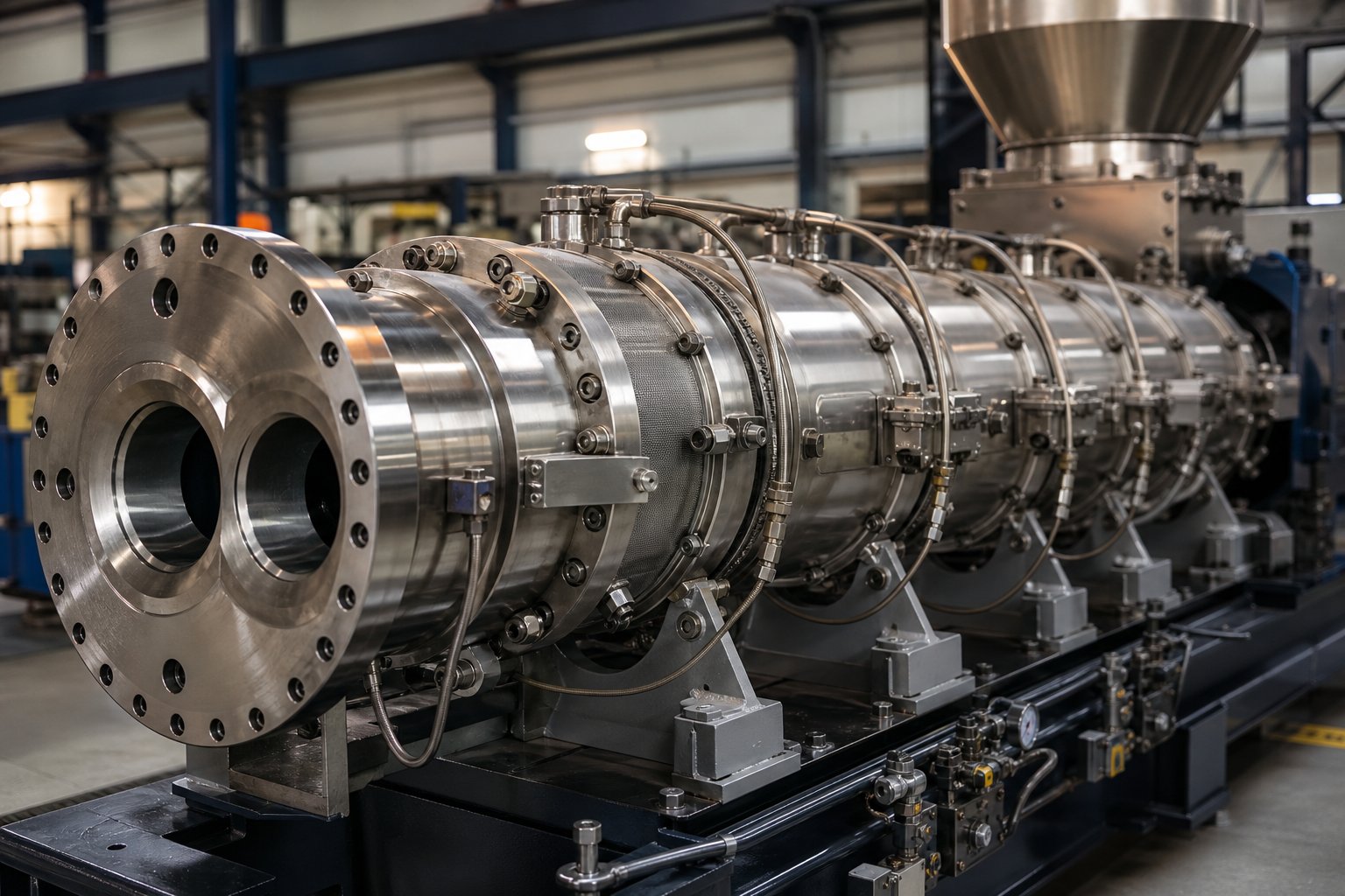
Twin screw extruder barrels are the modular, cylindrical housing structures that enclose the two intermeshing screws in a twin screw extruder. They provide the containment necessary for pressure buildup, manage heat transfer through integrated heating and cooling systems, and enable flexible process design by allowing different barrel segment types to be configured along the extruder's length.
In simpler terms, imagine a series of precision-bored steel segments bolted together in sequence, each one playing a specific role in the extrusion process. Inside this chamber, the twin screw elements rotate - melting, mixing, and pushing polymer material toward the die. The barrel walls serve as the thermal boundary, the pressure vessel, and the structural backbone of the entire system. Each barrel section can be independently heated or cooled, giving processors zone-by-zone temperature control that directly shapes melt quality and final product properties.
Unlike single-screw systems, twin-screw extruders rely on a figure-eight bore profile inside the barrel - two overlapping cylindrical bores machined to tight tolerances. This geometry is what allows fully intermeshing screws to wipe each other's surfaces and the barrel wall, creating the self-cleaning action that makes twin screw extrusion so effective for compounding, reactive processing, and devolatilization.
Why Barrel Design Is the Overlooked Key to Extrusion Quality
Most discussions about twin-screw extruders focus heavily on screw element configuration - kneading blocks, conveying elements, mixing zones. That focus is warranted, but it tells only half the story. The extruder screw barrel is where thermal management actually happens. It's where feed ports introduce raw material, where vent openings extract moisture and volatiles, and where side-feed inlets allow downstream addition of fillers or fibers. None of these functions belong to the screw. They belong to the barrel.
Consider the practical impact: barrel bore tolerances determine the clearance between screw flight tips and the barrel wall. As Technovel's technical documentation highlights, tip clearance design has a strong influence on dispersive mixing performance, thermal history, and self-cleaning capability. Too much clearance reduces shear and mixing efficiency. Too little clearance generates excessive heat from friction, risking polymer degradation. The barrel sets these boundaries.
Extruder barrels also define how modular and adaptable your process can be. Because modern twin screw barrels are segmented, you can reconfigure a single machine for vastly different applications - swapping a closed barrel segment for a vented one, adding a side-feed port, or extending the overall length-to-diameter ratio. This modularity is one of the reasons twin screw technology dominates compounding, recycling, and reactive extrusion across industries.
Whether you're new to extrusion and building foundational knowledge or an experienced processor evaluating material selection, wear patterns, and maintenance strategies, the barrel is where theory meets practice. The sections ahead break down every barrel segment type, walk through how barrel zones function during processing, and cover the metallurgy, wear mechanisms, and maintenance protocols that keep your operation running at peak performance.
Types of Modular Barrel Segments Explained
That modularity we just touched on is not an abstract concept - it's built into the physical hardware. Every twin screw barrel is assembled from individual segments, each engineered for a specific function. Swap one segment, and you change what the extruder can do at that position. Understanding what each segment type contributes is the foundation for configuring any compounding or processing line effectively.
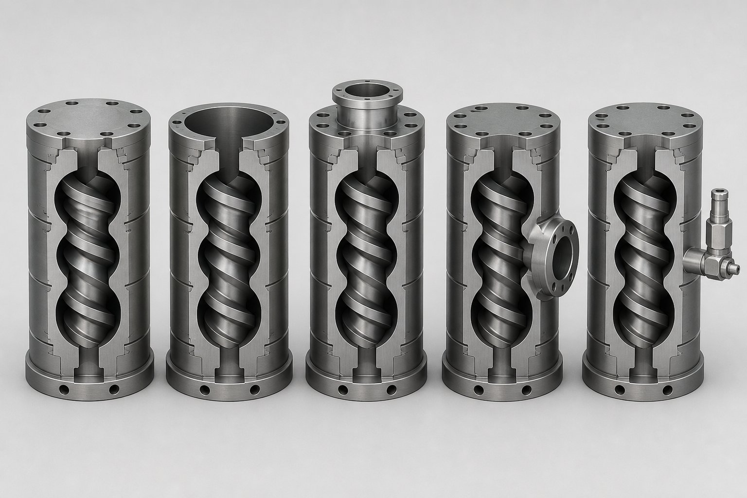
Closed Barrels, Feed Barrels, and Vented Segments
Every extruder barrel segment shares one feature: a precision-machined figure-eight bore through which the twin screws rotate. The differences lie in what else each segment offers beyond that bore.
Closed barrel segments are the most common type. They fully encase the melt on all sides, with no external openings other than ports for heating elements and cooling channels. As Plastics Technology notes, closed sections provide temperature control across the entire barrel circumference - something open segments cannot match - making them the default choice for conveying, melting, and mixing zones.
Open-top feed barrels feature an opening at the top of the segment through which raw material enters the extruder. The extruder feed barrel is typically positioned at the very first barrel station, where pellets, powders, or granules drop by gravity directly onto the screws. For low-bulk-density powders that tend to entrap air, a second open barrel can be placed upstream of the feed position as a back-vent, allowing entrained air to escape and improving feed consistency.
Vented or degassing barrels also use an open-top design, but their purpose is the opposite of feeding - they let volatiles out rather than letting material in. These segments are positioned in zones where the screw design reduces melt pressure to near-atmospheric levels, creating the conditions for moisture, trapped air, and volatile compounds to escape. Vents can operate at atmospheric pressure or connect to a vacuum pump for more aggressive devolatilization. Without proper vent placement and screw coordination, vapors remain trapped in the melt, causing foaming, poor pellet quality, and surface defects in the final product.
Side-Feed and Liquid-Injection Barrel Configurations
Side-feed barrels introduce a second figure-eight opening on the side of the segment, designed to accept a twin-screw side stuffer. This configuration allows fillers, fibers, glass reinforcements, or other additives to be introduced downstream - after the polymer has already melted. Feeding abrasive additives like glass fiber directly into a molten stream, rather than through the main feed throat, protects the upstream barrel and screw elements from unnecessary wear. A compact variation known as a back-vent combi-barrel combines a side-feed port with a small upstream atmospheric vent in a single segment, letting entrained air escape right where the additive enters.
Liquid-injection barrels are fitted with one or more injection ports that accept nozzles or injectors for introducing liquids directly into the melt stream. Oils, peroxides, liquid colorants, coupling agents, and water (for crosslinking or foaming processes) are typical examples. The injection port is sealed and pressurized to overcome melt pressure inside the barrel, ensuring accurate, consistent dosing without backflow.
How Barrel Segments Are Arranged Along the Extruder
Each twin screw barrel segment is typically four to six diameters long and bolts to the adjacent segments in sequence along the extruder frame. The arrangement follows the logic of the process itself: material enters, melts, mixes, vents, and exits. A practical way to visualize this is the table below, which maps each segment type to its role, typical position, and a real-world application.
| Barrel Segment Type | Primary Function | Typical Zone Placement | Application Example |
|---|---|---|---|
| Closed Barrel | Full containment; heating and cooling on all sides | Melting, mixing, metering zones | Conveying and compounding polymer blends |
| Open-Top Feed Barrel | Material introduction via gravity or forced feeding | Barrel position 1 (main feed) | Feeding pellets or powder into the extruder |
| Vented / Degassing Barrel | Volatile, moisture, and air removal | Downstream, typically 1-2 positions before the die | Vacuum devolatilization of hygroscopic resins |
| Side-Feed Barrel | Downstream addition of solids via side stuffer | Mid-barrel (after melting zone) | Glass fiber or mineral filler addition |
| Liquid-Injection Barrel | Pressurized introduction of liquids into the melt | Mid-barrel or downstream, application-dependent | Peroxide dosing for reactive extrusion |
A typical barrel extruder configuration for a compounding line might look like this: an open feed barrel at position one, followed by several closed barrels for melting and initial mixing, a side-feed combi-barrel at position four or five for additive introduction, more closed barrels for distributive mixing, a vacuum-vented barrel near the discharge end, and a final closed barrel before the die. The entire assembled process section - barrel segments, heating bands, cooling channels, and instrumentation - defines the extruder's L/D ratio and its processing capability.
What makes this system powerful is its flexibility. The same machine frame, gearbox, and motor can support entirely different processes simply by rearranging or substituting barrel segments. That flexibility, however, only delivers results when each segment is paired with the right screw elements underneath it - a relationship that plays out zone by zone as material travels from feed throat to die.
How Barrel Zones Work Together During Extrusion
Knowing the segment types is one thing. Understanding how those segments function as a coordinated system - each zone handing off material in a progressively transformed state to the next - is where the twin screw extrusion process really comes into focus. Think of it like a relay race: every zone has a specific job, and if one zone fumbles, the zones downstream pay the price.
Here's the sequential journey material takes through a typical barrel configuration:
- Feeding Zone - Solid pellets, powders, or granules enter through the open-top feed barrel and are conveyed forward by large-pitch screw elements. No melting occurs here; the goal is consistent material intake.
- Melting / Plastication Zone - Barrel heaters and screw-generated shear work together to convert solid material into a uniform melt. Kneading blocks beneath closed barrel segments do the heavy lifting.
- Mixing Zone - Dispersive and distributive mixing ensures all components - polymers, additives, fillers - are blended into a homogeneous compound. Barrel temperature holds steady to prevent degradation.
- Venting / Degassing Zone - Pressure drops sharply beneath vented barrel segments, allowing moisture, trapped air, and volatile compounds to escape from the melt surface.
- Metering / Pumping Zone - Closed barrel segments and shallow-channel screw elements build stable, uniform melt pressure for consistent delivery through the die.
Each of these zones relies on a specific barrel segment design and a deliberate temperature control strategy. Let's walk through them in detail.
From Feeding to Melting - How Barrel Zones Initiate Processing
The feeding zone is deceptively simple. Raw material drops through the open feed barrel onto the screws, and large-pitch conveying elements push it downstream. But barrel design matters even here. The feed barrel is typically left unheated or set to a mild temperature - just enough to prevent condensation on the bore surface. Why not heat it aggressively? Because premature softening of polymer pellets at the feed throat causes them to stick together, bridge across the screw channels, and choke the intake. Some processors even run cooling water through the feed barrel jacket to keep the bore wall well below the polymer's softening point.
As the material advances into the first closed barrel segments, conditions change dramatically. This is the melting or plastication zone, where the real transformation begins. Barrel heaters - typically electric cartridge or band heaters clamped around each segment - raise the bore wall temperature to match the polymer's processing range. For most commodity and engineering plastics, that means settings between 150 degrees C and 280 degrees C, though high-performance polymers can push barrel temperatures up to 450 degrees C depending on the resin system.
Here's an important nuance: the barrel doesn't melt the polymer alone. In twin screw extrusion, the majority of melting energy comes from viscous dissipation - the shear heat generated as kneading blocks and mixing elements work the material between the screws and against the barrel wall. The barrel's role is to supplement that shear energy with conducted heat and, critically, to prevent cold spots that would leave unmelted particles in the stream. You can think of the barrel as setting the thermal floor while the extrusion screw elements supply the mechanical energy that pushes melt conversion forward.
Mixing, Degassing, and Metering Zones in Practice
Once the polymer is fully molten, it enters the mixing zone - typically a series of closed barrel segments positioned over kneading blocks, gear-type mixing elements, or specialized distributive elements. Two distinct mixing actions happen here. Dispersive mixing breaks apart agglomerates of fillers, pigments, or additive clusters by applying high shear stress. Distributive mixing then spreads those broken-down particles uniformly throughout the melt. Both actions depend on the barrel maintaining a stable, well-controlled temperature. If the barrel runs too hot, polymer chains degrade. Too cold, and melt viscosity rises to the point where mixing elements can't generate enough flow to distribute components evenly.
The venting zone follows mixing, and it operates on a completely different principle. Imagine the melt flowing from a high-pressure mixing region into a zone where the screw design suddenly opens up - large-pitch conveying elements with deep channels reduce the degree of fill and drop the pressure to near atmospheric levels. At the same time, a vented barrel segment provides an opening to the atmosphere or connects to a vacuum pump. With pressure relieved and surface area exposed, moisture, residual monomers, solvents, and trapped air flash out of the melt. The barrel segment itself plays a passive but essential structural role: it provides the port geometry, seals against the adjacent segments, and supports any vacuum hardware mounted above. Meanwhile, reverse-flight or reverse kneading elements positioned just upstream of the vent create a melt seal that prevents molten polymer from flowing backward and flooding out through the vent opening.
Finally, the metering or pumping zone brings the process to a controlled conclusion. Closed barrel segments in this final section surround shallow-channel, small-pitch screw elements that compress the melt and build back pressure. This zone's job is consistency: delivering material to the die at a steady pressure, uniform temperature, and constant flow rate. Barrel temperatures here are typically set close to the target exit melt temperature, and adjustments tend to be small and deliberate. An unstable metering zone shows up immediately as die pressure fluctuations, uneven strand thickness, or inconsistent pellet weight downstream.
Temperature Control Across Barrel Zones
Every zone just described depends on precise thermal management, and that management lives inside the barrel walls. Each segment houses both heating elements and cooling channels - usually drilled passages through which water or oil circulates. Heating brings the bore wall up to the target setpoint. Cooling pulls excess energy away when screw-generated shear produces more heat than the process needs.
This dual capability matters more than many operators realize. In the melting zone, the barrel may call for heavy heating early in a startup but transition to cooling once the process reaches steady state and viscous dissipation takes over. In the mixing zone, barrels commonly run in a cooling-dominant mode because kneading blocks generate substantial shear heat. As Streamline Extrusion's process analysis points out, temperature differences exceeding 100 degrees F between blocks within a single zone have been recorded after cooling channels became fouled with scale buildup - a clear reminder that thermal control depends on hardware maintenance, not just setpoint accuracy.
Thermocouple placement also introduces a subtle but real complication. Most barrel segments position their thermocouples partway into the barrel wall, not at the bore surface. That means the temperature reading represents the bulk metal temperature, not exactly what the polymer sees. When a zone is actively heating, the actual bore wall temperature will be slightly lower than the thermocouple reads. When cooling, it will be slightly higher. Experienced processors account for this offset when fine-tuning their screw extrusion profiles, particularly in zones where even small temperature deviations affect product quality - like the venting zone, where overheating can drive unwanted side reactions, or the metering zone, where temperature swings translate directly into pressure instability at the die.
The takeaway is straightforward: barrel zones are not independent islands. They form a continuous thermal and mechanical chain, where the output condition of one zone becomes the input condition of the next. A feeding zone that runs too warm creates premature melt that disrupts conveying. A mixing zone that overheats sends degraded polymer into the vent. A metering zone with fouled cooling channels produces surging die pressure. Every zone earns its keep only when its barrel segment, temperature profile, and corresponding screw elements are all working in concert - which raises an equally important question about what those barrel segments are actually made of and how material choice determines service life.
Barrel Materials and Metallurgy for Maximum Wear Life
The best barrel zone configuration in the world means nothing if the barrel bore erodes, corrodes, or scores within a few thousand operating hours. Material selection is the single biggest factor separating a screw barrel that lasts 20,000 hours from one that fails at 4,000 - and the decision hinges on understanding exactly what your process does to the metal surface.
Nitrided Steel Barrels and Their Limitations
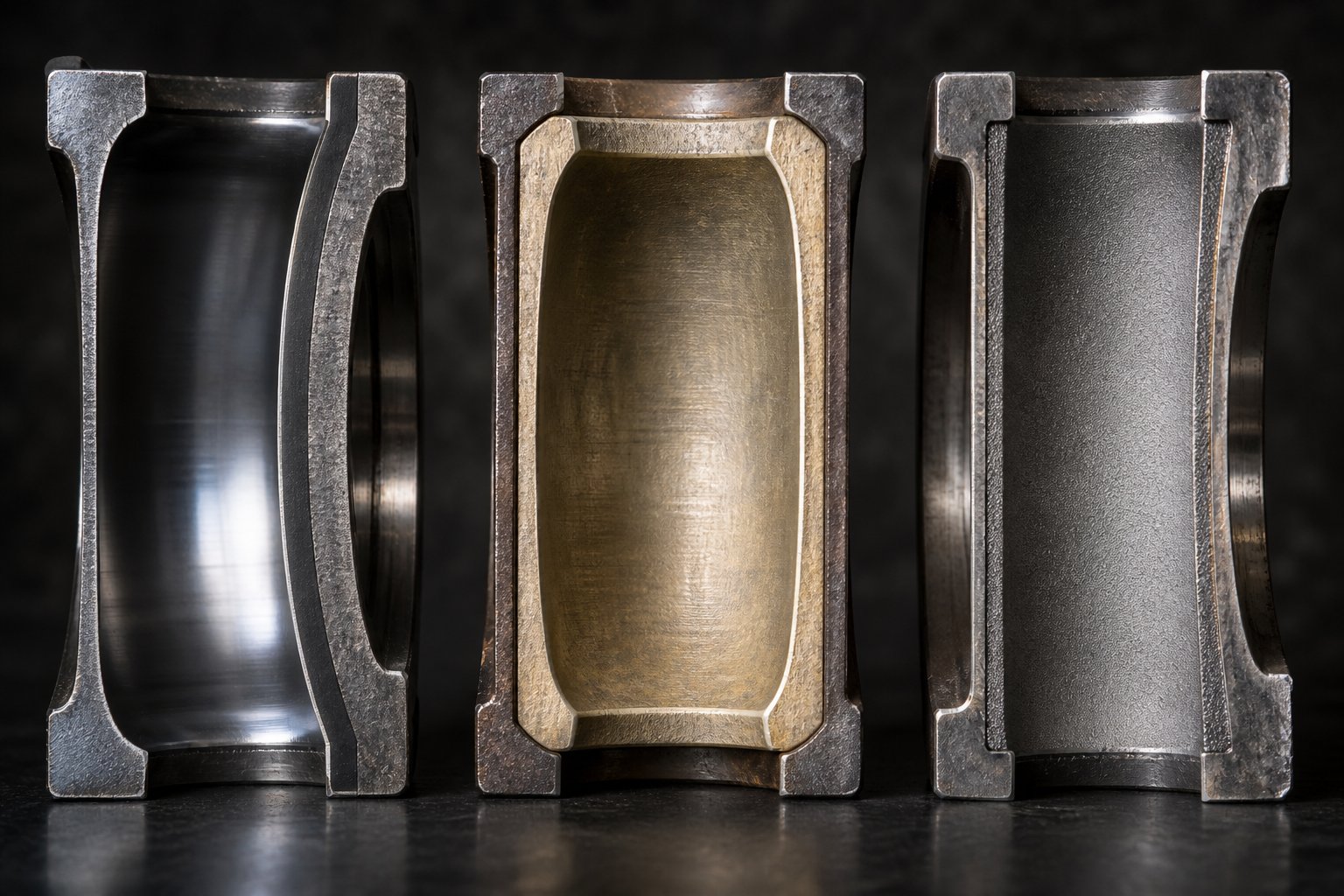
Standard nitrided steel barrels represent the entry point for most extrusion applications. The process works like this: a barrel machined from 4140 or equivalent alloy steel undergoes gas nitriding, where nitrogen diffuses into the bore surface at 480 to 530 degrees C, forming a hardened case of iron nitride and alloy nitride compounds. Surface hardness typically reaches 55 to 62 HRC, which sounds impressive - until you consider the depth. The nitrided case is only 0.3 to 0.7 mm deep. Once abrasive fillers or corrosive degradation products eat through that thin layer, you're left with a relatively soft substrate that wears at an accelerating rate.
For unfilled commodity polymers like polyethylene and polypropylene, nitrided barrels perform adequately. Push beyond that into glass-filled compounds or chemically aggressive resins, and the limitations surface quickly. Corrosive wear rates for nitrided 4140 steel in rigid PVC service run roughly 0.08 to 0.15 mm per 1,000 operating hours - a pace that can compromise bore tolerances within a single production campaign.
Bimetallic Linings for Abrasive and Corrosive Environments
Bimetallic extrusion barrel construction solves the shallow-case problem by centrifugally casting a wear-resistant alloy liner inside a tough outer steel shell. The liner bonds metallurgically to the barrel body, creating a composite structure that combines bore hardness with structural integrity.
Two alloy families dominate this space, each targeting a different wear mechanism:
- Iron-based bimetallic liners (such as high-chromium, tungsten carbide-reinforced alloys) deliver bore hardness of 60 to 72 HRC with liner thickness around 2.0 to 2.5 mm. They excel in abrasive service - calcium carbonate-filled polyolefins, talc-loaded compounds, and moderate glass fiber concentrations. Think of them as the workhorse choice for twin screw and barrel assemblies processing mineral-filled formulations.
- Nickel-based bimetallic liners swap the iron matrix for a nickel-chromium matrix embedded with tungsten carbides. The result is a bore surface that resists chemical attack from hydrogen chloride and other acidic degradation products while still handling moderate abrasion. This is the standard specification for PVC processing, halogenated flame retardant compounds, and CPVC, where corrosion - not abrasion - is the primary failure driver.
The practical difference is significant. Nickel-based liners reduce corrosive wear rates to roughly 0.01 to 0.03 mm per 1,000 hours in PVC service - a five- to eightfold improvement over nitrided steel. For processors running chlorinated or fluorinated polymers, this metallurgy choice often determines whether a barrel lasts months or years.
Tungsten Carbide and Advanced Coating Technologies
When filler loading climbs above 30% glass fiber or includes highly abrasive ceramic microspheres, even iron-based bimetallic liners face accelerated wear. This is where tungsten carbide enters the picture. Applied via high-velocity oxygen fuel (HVOF) thermal spray, tungsten carbide coatings achieve hardness levels of 1,100 to 1,400 HV - roughly equivalent to 70+ HRC - making them second only to diamond among common industrial materials.
The coating is typically 0.15 to 0.35 mm thick with porosity below 1% and bond strength exceeding 70 MPa. In severely abrasive compounding, WC-coated bores deliver service life extensions that justify their premium cost tier. A variant worth knowing: WC-CrC-NiCr formulations replace the traditional cobalt binder with nickel-chromium, cutting corrosion vulnerability by five to eight times while maintaining hardness above 1,000 HV. This makes them the go-to solution for the toughest scenario of all - high glass fiber loading combined with corrosive polymer chemistry.
The table below puts these material options side by side so you can match your process conditions to the right metallurgy:
| Barrel Material | Bore Hardness | Corrosion Resistance | Abrasion Resistance | Typical Applications | Relative Cost |
|---|---|---|---|---|---|
| Nitrided Steel (4140) | 55-62 HRC (surface) | Low | Moderate (shallow case) | Unfilled PE, PP, PS | $ |
| Iron-Based Bimetallic | 60-72 HRC | Moderate | High | CaCO3, talc, moderate glass-filled compounds | $$ |
| Nickel-Based Bimetallic | 55-65 HRC | High | Moderate to High | PVC, CPVC, halogenated FR compounds | $$$ |
| HVOF Tungsten Carbide (WC-Co) | 1,100-1,400 HV (~70+ HRC equiv.) | Moderate | Very High | High glass fiber (30%+), ceramic fillers | $$$$ |
| WC-CrC-NiCr Coating | 1,000+ HV (~65+ HRC equiv.) | High | Very High | Glass fiber + corrosive resins | $$$$+ |
Choosing barrel metallurgy is ultimately a wear-mechanism matching exercise. Abrasive processes demand hard carbide structures. Corrosive processes demand chemically resistant matrices. The most punishing applications - imagine 40% glass-filled nylon compounded at high throughput - demand both. Getting this match right determines not just how long your screw barrel lasts, but how consistently it performs throughout its service life, since bore diameter growth from wear directly changes the clearance relationship between barrel and screw - a relationship that shapes everything from mixing quality to energy consumption.
Barrel vs. Screw: Understanding the Division of Labor
That clearance relationship between bore wall and screw flight tips isn't just a maintenance concern - it's a window into something more fundamental. The extruder screw and barrel perform very different jobs, yet discussions about extrusion performance tend to blur them together. Think of a piston engine: the piston does the pushing, but the cylinder provides the containment, cooling, and structural precision that makes the push productive. Twin screw extrusion works the same way. Separating what each component actually does clarifies why both deserve equal engineering attention.
What the Barrel Does That the Screw Cannot
Extruder screws generate shear, convey material forward, and perform mixing through element geometry - kneading blocks, mixing gears, and conveying flights all create mechanical action. Remove the screws, and you lose all material transport and shear energy. But remove the barrel, and you lose something equally critical: the entire thermal management system, every material introduction point, and every gas extraction port.
The barrel alone provides heating through embedded cartridge or band heaters and cooling through drilled water or oil channels. The barrel alone provides feed ports, side-feed openings, and liquid-injection points. The barrel alone provides vent openings for atmospheric or vacuum degassing. None of these functions live on the screw - they are fixed infrastructure that the screw works within.
Here's how the responsibilities break down across the major process categories:
| Process Category | Barrel Responsibilities | Screw Responsibilities |
|---|---|---|
| Thermal Management | Heating (heater bands/cartridges), cooling (water/oil channels), thermocouple housing for zone temperature feedback | Generates shear heat through viscous dissipation; does not actively heat or cool |
| Material Introduction | Provides main feed port, side-feed ports, and liquid-injection ports | Conveys incoming material away from feed openings; creates starved zones to accept downstream additions |
| Material Transport | Provides containment and pressure boundary; stationary bore surface creates drag flow against screw rotation | Actively conveys material forward (or backward) through flight geometry and rotation |
| Mixing Action | Supplies the stationary wall surface against which shear stress develops | Generates dispersive and distributive mixing through kneading blocks, gear mixers, and element sequencing |
| Degassing / Venting | Provides vent ports (atmospheric or vacuum) and sealing surfaces for vacuum hardware | Creates low-pressure zones beneath vents using reverse elements or deep-channel conveying sections |
| Wear Surfaces | Bore liner absorbs abrasive and corrosive contact; metallurgy is selected for process chemistry | Flight tips and element surfaces wear against bore wall; hard-facing or coating protects flight lands |
| Structural Containment | Withstands internal melt pressure (often 50-200+ bar); provides rigid alignment for screw centerline | Operates within the bore; does not provide containment |
You'll notice a clear pattern: the screw is the active, moving component that does the mechanical work. The barrel is the passive, stationary component that defines the boundaries, manages energy, and provides every access point into the process. Neither functions without the other, but they fail for very different reasons and demand different engineering priorities.
How Barrel Bore Geometry Affects Screw Performance
The barrel's inner diameter doesn't just house the screws - it directly governs how well they perform. In a co-rotating intermeshing twin screw system, the figure-eight bore profile is machined to tolerances typically within 0.01 to 0.03 mm of nominal diameter. That precision determines the flight clearance - the gap between screw flight tip and bore wall - which for most extruder screws and barrels falls in the range of 0.1 to 0.2 mm per side on a 100 mm diameter machine.
Why does that tiny gap matter so much? Three reasons:
- Self-wiping efficiency. Tighter clearances mean the screw flights sweep closer to the barrel wall and closer to each other, leaving less residual material clinging to surfaces. This is the self-cleaning action that makes twin screw extrusion ideal for frequent product changeovers and color transitions. As bore wear increases that clearance, self-wiping degrades, and more material stagnates in dead zones where it can degrade thermally.
- Shear rate distribution. The shear rate in the flight clearance zone is inversely proportional to the gap width. A 0.15 mm clearance produces dramatically higher localized shear than a 0.30 mm clearance at the same screw speed. That high-shear zone at the flight tip is critical for dispersive mixing - breaking down filler agglomerates and distributing pigments. When bore wear doubles the gap, the peak shear rate in that zone drops, and mixing quality suffers before any other symptom appears.
- Leakage flow. Material that slips backward over the flight tip instead of being conveyed forward is called leakage flow. Wider clearances increase leakage, reducing the extruder screw's pumping efficiency and generating additional heat without doing productive work. The practical effect is lower throughput at the same screw speed and higher melt temperatures - exactly the symptoms described in wear analysis research from Plastics Technology.
The barrel, in other words, sets the dimensional stage on which every screw element performs. A perfectly designed screw running inside a worn barrel will underperform a basic screw running inside a tight, well-maintained bore. That's why seasoned processors measure bore diameter at regular intervals and track the trend over time - because the barrel's tolerances silently shape mixing quality, throughput stability, and energy efficiency every hour the extruder runs.
Of course, knowing what each component does in isolation only gets you halfway. The real complexity - and the most common source of processing failures - lies in how barrel segments and screw elements must be deliberately paired at each position along the machine.
How Barrel Configuration Must Match Screw Element Design
Imagine placing a vacuum vent directly over a set of high-pressure kneading blocks. What happens? Molten polymer shoots straight out of the vent port. Or picture a side-feed barrel positioned over a fully filled screw section - the incoming filler has nowhere to go, backs up into the stuffer, and chokes the feed. These aren't hypothetical scenarios. They're real processing failures that happen when barrel segments and screw elements aren't deliberately paired at each station along the extruder.
The principle is straightforward: every barrel segment type demands a specific screw geometry beneath it to function correctly. Violate that pairing, and the barrel opening becomes a liability instead of a tool.
Matching Barrel Segments to Screw Elements
Each barrel position along a twin screw extruder serves a distinct unit operation - feeding, melting, mixing, venting, side-feeding, or pumping. The barrel segment provides the physical infrastructure (ports, heaters, cooling channels), while the screw elements beneath it supply the mechanical action. When these two components are properly coordinated, the process runs cleanly. When they aren't, problems surface immediately.
Here's how the key pairings work:
- Open feed barrel + large-pitch conveying elements. The feed barrel's opening lets raw material drop onto the screws. Beneath it, wide-pitch conveying elements with deep channels pull material away from the feed port quickly, preventing backup. If you place restrictive elements like kneading blocks under a feed barrel, material piles up in the throat and bridges - especially with powders or low-bulk-density feedstocks.
- Closed barrel segments + kneading blocks or mixing elements. The melting and mixing zones rely on closed barrels that provide full circumferential heating and cooling. Kneading blocks beneath these segments generate intense shear, and the closed barrel contains the resulting melt pressure while managing the heat produced. Placing kneading blocks under an open or vented barrel would allow polymer to escape through the opening rather than building the pressure needed for effective mixing.
- Vented barrel + reverse-flight elements or deep-channel conveying sections. This is where the coordination becomes critical. The vent port only works if the melt pressure directly beneath it is low - ideally near atmospheric. Reverse-flight elements or reverse kneading blocks positioned just upstream of the vent create a melt seal that holds back pressure from the mixing zone. Downstream of this seal, large-pitch conveying elements reduce the degree of fill, exposing thin layers of melt surface from which volatiles can escape. As industry experts at CPM Century Extrusion emphasize, stable vent operation requires both a low degree of fill in the vent zone and a reliable melt seal upstream of the opening.
- Side-feed barrel + starved conveying zone. A side-feed barrel introduces downstream additives via a twin-screw stuffer. The extruder screw elements beneath this port must create a partially filled, low-pressure zone so the incoming filler has space to enter the melt stream. If the screw section is fully filled - say, due to an overly restrictive element downstream - the stuffer can't push material into the barrel, and the additive backs up or gets ground between the stuffer screws.
- Liquid-injection barrel + moderate-pressure conveying zone. Liquid injection requires enough melt pressure to prevent backflow through the injection nozzle, but not so much that the injector can't overcome it. The screw geometry beneath the injection port needs to maintain a stable, moderate pressure level - typically achieved with standard-pitch conveying elements followed by a mild restrictive element downstream.
Think of each barrel-screw pairing as a contract: the barrel provides access and thermal control, the screw provides the right pressure and fill conditions. Break the contract at any station, and that unit operation fails.
Co-Rotating vs. Counter-Rotating Barrel Design Differences
The matching logic described above applies universally, but the barrel hardware itself differs depending on whether you're running a co rotating twin screw extruder or a counter-rotating configuration. These aren't interchangeable platforms - each imposes distinct requirements on barrel bore geometry, thermal management, and segment design.
In a co-rotating parallel twin screw extruder, both screws turn in the same direction inside a parallel figure-eight bore. The self-wiping action between screws and between screw flights and the barrel wall is what makes this configuration dominant in compounding and reactive extrusion. Barrel segments are typically four to six diameters long, bolted in modular sequence, and fully interchangeable along the process section. The bore profile maintains consistent center distance and tight tolerances because self-wiping efficiency depends directly on clearance precision. Most of the modular barrel flexibility discussed throughout this article - feed barrels, vent barrels, side-feed combis - originates from co-rotating platform design.
A conical twin screw extruder, by contrast, uses counter-rotating screws that taper from a larger diameter at the feed end to a smaller diameter at the discharge. This geometry inherently generates high forwarding pressure and gentle mixing - ideal for shear-sensitive materials like PVC. Barrel design reflects this taper: segments aren't interchangeable between positions because bore diameter changes along the length. Thermal zones are often fewer, and modular reconfiguration is far more limited than on a parallel machine.
Parallel counter-rotating designs also exist, featuring straight (non-tapered) bores with screws that rotate in opposite directions. Compared to co rotating and counter rotating twin screw extruder platforms side by side, the counter-rotating version produces a calendering or squeezing action between the screws rather than the rolling, self-wiping flow of co-rotating pairs. Barrel bore tolerances for counter-rotating machines must account for different pressure distributions - the intermesh zone in a counter-rotating system sees higher localized pressure than in a co-rotating system, which affects bore wear patterns and cooling channel placement.
The practical takeaway? Barrel segments designed for a co-rotating extruder cannot simply be installed on a counter-rotating machine, even if the nominal bore diameter matches. The bore geometry, center distance, pressure profiles, and thermal demands are fundamentally different between these architectures.
Common Configuration Mistakes and Their Consequences
Even experienced processors make configuration errors - sometimes inherited from a previous setup, sometimes introduced during a process change. The most frequent mistakes fall into a few predictable categories:
- Vent flooding from incorrect vent placement. Positioning a vacuum vent too close to the die shortens the pumping length available to build die pressure. As head pressure rises - from screen fouling, die restriction, or viscosity changes - the backup length of filled screw extends upstream until it reaches the vent opening. Molten polymer then flows continuously out of the vent, fouling the vacuum system and requiring operator intervention or line shutdown. Industry guidance recommends placing the vacuum vent at least two barrel sections upstream of the die to eliminate this risk.
- Feed bridging from wrong screw elements under the feed barrel. Restrictive elements - kneading blocks or narrow-pitch conveyors - placed directly beneath the feed opening slow material intake and allow polymer to soften, stick, and bridge across the feed throat. This is particularly problematic with low-melting-point polymers or hygroscopic powders that absorb ambient moisture and become tacky. The fix is simple: always use deep-channel, large-pitch conveying elements under the feed port, and keep the feed barrel temperature low enough to prevent premature softening.
- Premature degradation from overheated kneading zones. When barrel heating setpoints in the mixing zone are too aggressive - or when cooling channels are fouled and can't remove shear heat effectively - the melt temperature climbs well above the target processing range. The result is molecular weight reduction, discoloration, off-gassing, and in severe cases, carbonized material that contaminates the product stream. Matching the barrel's thermal capacity to the shear intensity of the screw elements beneath it is essential. High-energy kneading blocks need barrel segments with robust cooling capability, not just high-wattage heaters.
- Side-feed starvation from fully filled screw zones. If the screw section beneath a side-feed barrel is running at full fill - due to an upstream restriction or an improperly sequenced restrictive element - there's no available volume for the incoming additive. The stuffer motor draws excessive current, filler backs up into the feed hopper, and throughput of the additive drops below target. Creating a deliberate starve zone with large-pitch conveying elements at the side-feed position solves the problem.
Each of these failures traces back to the same root cause: a mismatch between what the barrel segment needs at that position and what the screw geometry beneath it delivers. The barrel provides the opening, the port, or the thermal environment. The screw must provide the corresponding pressure, fill level, or mechanical action. Get one side wrong, and the other can't compensate.
Configuration matching protects your process from these pitfalls, but even a perfectly configured barrel eventually faces a different kind of challenge - one that no amount of screw-element shuffling can prevent. The bore surface itself wears, erodes, and corrodes over thousands of operating hours, and recognizing the early signs of that degradation is what separates proactive maintenance from costly emergency shutdowns.

Barrel Wear Mechanisms and Failure Analysis
A perfectly configured screw and barrel assembly doesn't stay perfect forever. Every operating hour chips away at that precision-machined bore surface - sometimes literally. Recognizing how your barrel is wearing, and catching it early, is the difference between a planned replacement during scheduled downtime and a catastrophic failure that shuts your line down mid-run.
Three distinct wear mechanisms account for nearly all barrel bore degradation. Each one attacks the metal differently, progresses at its own pace, and demands a different response.
Abrasive, Corrosive, and Adhesive Wear Explained
Abrasive wear is the most common culprit, responsible for roughly 50% of all screw and barrel wear cases. Hard particles in the compound - glass fibers, calcium carbonate, talc, titanium dioxide, ceramic microspheres - physically grind against the bore surface as the screws convey and mix material. Imagine fine sandpaper spinning inside a steel tube at high speed, hour after hour. The result is progressive bore enlargement, with wear rates typically running 0.05 to 0.15 mm per 1,000 operating hours depending on filler type, loading percentage, and barrel metallurgy. The melting and mixing zones take the worst punishment because that's where filler particles are under the highest shear stress against the barrel wall.
Corrosive wear attacks the bore chemistry rather than its surface hardness. Acidic degradation products - hydrogen chloride from PVC processing, hydrofluoric acid from fluoropolymers, acidic off-gases from certain flame retardants - react with the barrel metal at processing temperatures, forming brittle oxide or chloride layers that flake away and expose fresh metal to further attack. This mechanism accounts for about 15% of extrusion screw barrel failures, but its impact is outsized in specific applications. Corrosive wear rates range from 0.01 to 0.05 mm per 1,000 hours, slower than abrasion in absolute terms but insidious because it often goes undetected until bore measurements reveal unexpected diameter growth.
Adhesive wear results from metal-to-metal contact between screw flight tips and the barrel wall. Under normal conditions, a thin film of molten polymer separates these surfaces. But when thermal expansion causes screw elements to grow toward the bore wall, or when barrel-to-barrel misalignment shifts the screw centerline off-axis, that protective film breaks down. Direct metal contact produces galling, scoring, and material transfer - small patches of screw metal welding momentarily to the barrel bore and tearing away. This mechanism drives roughly 30% of wear cases and is especially damaging because it escalates rapidly: initial scoring creates rough spots that generate more friction, more heat, and more scoring.
Early Warning Signs of Barrel Degradation
Barrel wear rarely announces itself with a dramatic failure. Instead, it whispers through subtle process changes that attentive operators can catch - if they know what to look for. The challenge is that many of these symptoms overlap with other process issues, so recognizing the pattern matters as much as spotting any single indicator.
Watch for these key signals:
- Rising melt temperature despite stable barrel setpoints. As bore clearance increases from wear, leakage flow over screw flight tips generates additional shear heat without contributing to forward transport. The melt gets hotter even though nothing changed on the control panel.
- Declining output at constant screw speed. Wider clearances reduce pumping efficiency. Material that should be conveyed forward instead slips backward over worn flight gaps. You compensate by increasing screw speed, which accelerates wear further - a vicious cycle.
- Increasing motor current or specific energy consumption. The extruder works harder to achieve the same throughput as barrel and screw clearances open up. Industry benchmarks suggest that motor current deviations exceeding 15% above baseline warrant immediate investigation.
- Visible scoring or galling on the barrel bore during inspection. Axial scratches, circumferential gouges, or rough patches on the bore surface indicate adhesive or abrasive contact that has progressed beyond the initial stages.
- Material leakage at barrel segment joints. When bore wear causes higher internal pressures or when gasket faces degrade, polymer seeps between segments - a clear indicator that bore tolerances have shifted.
- Declining product quality without recipe changes. Undispersed filler agglomerates, inconsistent color, or increased gel counts can all trace back to the reduced shear and mixing efficiency that comes with a worn bore.
Any one of these symptoms could have other explanations. Two or three appearing simultaneously in a barrel that has several thousand operating hours? That's the bore telling you it needs measurement.
Measuring Barrel Bore Wear and Setting Replacement Thresholds
Subjective assessment isn't enough. Quantifying bore wear requires a precision bore gauge - a calibrated instrument that measures internal diameter at multiple points along the barrel length. The measurement procedure follows a disciplined sequence: first, clean the barrel thoroughly while it's still warm, removing all residual polymer with bore brushes and abrasive pads. Then allow the barrel to cool to ambient temperature before inserting the gauge, since thermal expansion at processing temperatures would distort the readings.
Set the bore gauge to the original OEM bore diameter plus the manufacturer's specified tolerance - typically +0.001 inches (0.025 mm) for new barrels. Take readings at one-inch increments along the bore length, recording the deviation from nominal at each point. Focus your measurements on the transition and high-shear zones where wear concentrates most heavily. Critically, avoid inserting the gauge into the feed port opening, where the measuring head can be damaged and where readings aren't representative of bore condition.
So when does the data say "replace"? Industry-standard thresholds vary by bore diameter, but general guidelines are instructive:
| Indicator | Normal Range | Action Threshold |
|---|---|---|
| Bore ID increase per year | Less than 0.05 mm | Greater than 0.10 mm/year - reline or replace |
| Total bore diameter growth | Within OEM tolerance | Exceeding 0.15-0.20 mm above nominal - evaluate replacement |
| Flight-to-bore clearance (per side) | 0.05-0.10 mm | Greater than 0.15 mm - performance degradation likely |
| Motor current deviation | Baseline +/- 5% | Greater than baseline +15% - investigate wear |
Track these numbers over time, not just at a single inspection. A barrel showing 0.08 mm total wear after 6,000 hours is on a very different trajectory than one showing the same number after 2,000 hours. Plotting wear rate against operating hours reveals whether degradation is linear - typical of steady abrasive wear - or accelerating, which often signals that a bimetallic liner has been breached and the softer substrate is now exposed.
The data also drives the repair-versus-replace decision. A barrel with uniform, moderate wear across its length may be a candidate for relining - centrifugally casting a fresh bimetallic liner inside the existing shell. A barrel with localized deep scoring, out-of-round bore sections, or cracking at bolt holes has typically passed the point of economical repair and needs full replacement. Knowing these thresholds before you need them - not during an emergency shutdown - is the foundation of a maintenance strategy that keeps your line running predictably and profitably.
Barrel Maintenance, Alignment, and Inspection Protocols
Knowing when a barrel needs replacement is valuable. Knowing how to push that replacement date as far into the future as possible - without sacrificing process quality - is where the real money is. A proactive maintenance program doesn't just extend barrel life; it stabilizes your process, protects your screws, and prevents the kind of unplanned shutdowns that cost far more than any scheduled maintenance window ever will. Yet surprisingly, most operations run their twin screws with little more than a reactive approach: fix it when it breaks.
That approach is expensive. Industry data suggests that proactive maintenance programs reduce twin screw extruder operating costs by 20 to 30% compared to reactive strategies. The difference comes down to discipline - regular inspections, documented procedures, and a schedule that treats barrel care as a production investment rather than an interruption.
Preventive Maintenance Schedules for Twin Screw Barrels
Effective barrel maintenance isn't a single annual event. It's a layered program with daily, weekly, monthly, and quarterly checkpoints - each targeting different failure modes before they escalate.
Daily and weekly tasks are quick but essential. Before every startup, verify that all barrel zone heaters are functioning and that thermocouple readings respond within expected ranges. Check cooling water flow rates visually or through flow indicators on each barrel segment. Look for polymer leakage at barrel joint faces - even a thin film of material seeping between segments signals gasket degradation or alignment drift that will worsen under continued operation. Weekly visual inspections alone can prevent roughly 80% of extruder failures, according to maintenance engineering assessments from twin screw extruder manufacturers.
Monthly tasks go deeper. Performance testing should track output rate, motor current draw, and melt temperature against baseline values recorded when the barrel was new or freshly relined. Deviations in any of these metrics - especially when they trend in the same direction over consecutive months - point toward bore wear or thermal system degradation. Verify torque on barrel bolts using calibrated torque wrenches at the manufacturer's specified values. Thermal cycling loosens bolts over time, and undertorqued joints lead to misalignment, leakage, and accelerated wear at segment interfaces.
Quarterly and annual inspections require pulling the screws and directly examining the bore. Use calibrated bore gauges to measure internal diameter at one-inch increments, focusing on the high-shear zones identified in your wear history. Flush all cooling channels with a descaling solution to remove mineral deposits that reduce heat transfer efficiency. Scale buildup inside cooling passages is one of the most overlooked causes of thermal control problems - a fouled channel can reduce cooling capacity by 30% or more, creating hot spots that degrade polymer and accelerate bore wear. Calibrate all thermocouples against a reference standard, replacing any that read more than 2 to 3 degrees outside tolerance.
Here's a practical schedule to anchor your program:
| Interval | Maintenance Task | Purpose |
|---|---|---|
| Daily / Startup | Verify heater function, thermocouple response, cooling flow | Catch heating/cooling failures before they affect product |
| Weekly | Visual inspection of barrel joints, vent ports, feed area | Detect leakage, buildup, or gasket deterioration early |
| Monthly | Performance baseline comparison (output, motor amps, melt temp); bolt torque verification | Track wear progression; prevent joint loosening |
| Quarterly | Pull screws; bore gauge measurement; cooling channel flush; thermocouple calibration | Quantify bore wear; restore thermal performance |
| Annually | Full disassembly; gasket replacement; alignment verification; bore reconditioning evaluation | Comprehensive assessment of remaining barrel life |
Document every reading. A single bore measurement tells you where you are. A series of measurements plotted over time tells you where you're headed - and whether your current metallurgy and operating conditions are sustainable or burning through barrel life faster than expected.
Barrel Alignment and Modular Assembly Best Practices
Modular barrel construction gives you flexibility, but it also introduces a failure mode that monolithic barrels don't have: misalignment at segment joints. When two barrel segments meet, their bores must form a perfectly continuous figure-eight channel. Even a fraction of a millimeter of offset at the joint creates a lip - a step change in bore diameter that screw flight tips slam into on every rotation. The consequences cascade quickly: localized adhesive wear at the joint, scoring on both the bore surface and flight tips, polymer stagnation in the resulting dead zone, and material leakage through the stressed gasket face.
Proper assembly starts with the alignment pins. Every modular barrel segment includes dowel pin holes that establish rotational and axial positioning relative to the adjacent segment. Before bolting segments together, verify that all alignment pins are present, undamaged, and seated fully. A missing or sheared pin allows rotational shift under the torque of barrel bolt tightening, and once the segments are heated to processing temperature, thermal expansion locks that misalignment in place.
Bolt torque sequencing matters just as much as the final torque value. Follow a star pattern - tightening opposing bolts in alternating sequence rather than working around the bolt circle - to distribute clamping force evenly across the gasket face. Under-tightening leaves gaps where polymer seeps through. Over-tightening can warp the flange, distorting the bore at the joint interface. The manufacturer's torque specification exists for a reason: it accounts for the bolt material, gasket compression characteristics, and the thermal expansion the joint will experience during operation.
Speaking of thermal expansion - it's a factor many operators underestimate. A steel barrel segment running at 250 degrees C grows measurably in both length and diameter compared to its cold dimensions. The extruder frame's barrel support system must accommodate this growth, typically through sliding mounts that allow axial expansion toward the die end while keeping the feed-end position fixed relative to the gearbox. If support clamps are overtightened or if accumulated debris prevents the barrel from sliding freely, thermal stress builds at segment joints and can actually bow the barrel assembly off its centerline. Alignment specialists report that very few machines are properly aligned when checked - a reminder that this isn't a set-and-forget task.
After assembly, verify overall barrel straightness using a laser alignment system or precision straightedge before reinstalling the screws. Insert the screw elements and rotate them by hand through the full barrel length. They should turn freely without interference, tight spots, or audible contact. Any hangup indicates misalignment that will cause adhesive wear under power - a problem far cheaper to fix during assembly than during a mid-production failure.
When and How to Source Replacement Barrels
Even with disciplined maintenance, every barrel reaches end of life. Bore measurements will eventually cross the replacement threshold, cooling channels will corrode beyond effective flushing, or cracking at bolt holes will compromise structural integrity. How you handle the replacement process determines whether your downtime is measured in hours or weeks.
Planning ahead is non-negotiable. Lead times for custom or application-specific barrels from established twin-screw extruder manufacturer facilities can run four to twelve weeks depending on bore size, metallurgy, and configuration complexity. Waiting until bore measurements hit critical levels before placing an order virtually guarantees that you'll run degraded product quality while waiting for delivery - or shut the line down entirely.
The smarter approach is to establish replacement thresholds well before the barrel becomes unserviceable, and to have sourcing relationships in place before you need them. When evaluating suppliers, consider several factors beyond price:
- Metallurgy options. Does the manufacturer offer the full range of liner materials - nitrided, iron-based bimetallic, nickel-based bimetallic, and tungsten carbide coatings - matched to your specific process chemistry?
- Dimensional precision. Bore tolerances, center distance accuracy, and segment-to-segment alignment quality vary significantly between suppliers. Request inspection certificates with actual measured dimensions, not just nominal specifications.
- Application expertise. A supplier who understands your process - whether that's compounding, recycling, masterbatch, or reactive extrusion - can recommend the right metallurgy, cooling channel configuration, and segment layout for your operating conditions.
- Lead time and inventory. Some manufacturers maintain semi-finished barrel blanks in common sizes, dramatically shortening delivery for standard configurations.
For operations running compounding lines, recycling plants, or masterbatch production where barrel wear rates are inherently high, NANHAIYA's parallel twin screw barrel product line serves as a practical resource worth evaluating. Their barrels are engineered for the demands of high-wear processing applications - stable conveying, effective mixing, and resistance to abrasive and corrosive compounds - and they support both replacement and custom configurations for parallel twin screw platforms.
One additional consideration applies when acquiring a used twin screw extruder: always inspect the barrel bore condition before committing to the purchase. A used twin screw extruder may carry significant hidden wear that isn't apparent from external inspection. Request bore gauge measurements at multiple positions along the barrel length, and compare them against the OEM's original tolerance specifications. A machine with a worn-out barrel isn't necessarily a bad deal - but only if the replacement barrel cost is factored into your acquisition price and you've already identified a reliable source for the new barrel.
Barrel life expectancy varies enormously based on process conditions and maintenance practices. A nitrided steel barrel running unfilled polyolefins with proper maintenance can deliver 15,000 to 25,000 operating hours. A bimetallic barrel processing 30% glass-filled nylon might last 8,000 to 12,000 hours. A neglected barrel of any metallurgy - with fouled cooling channels, uncalibrated thermocouples, and loose segment bolts - can fail in half those intervals. The maintenance program you build around your barrels doesn't just protect the hardware. It protects every hour of production that hardware enables.
With maintenance protocols, alignment procedures, and replacement sourcing strategies established, the final piece of the puzzle comes into focus: how do you select the right barrel specification in the first place - matching bore diameter, metallurgy, segment configuration, and architecture to the specific demands of your processing application?
Selecting the Right Twin Screw Barrel for Your Operation
You know the segment types, the metallurgy options, the wear mechanisms, and the maintenance protocols. The question that ties everything together is deceptively simple: which barrel specification actually fits your process? Getting this wrong doesn't just cost money on the initial purchase - it compounds over every operating hour through premature wear, suboptimal mixing, or thermal control limitations that quietly erode product quality. Here's how to approach the decision systematically.
Key Decision Variables for Barrel Selection
Every barrel selection decision rests on four interconnected variables. Change any one of them, and the optimal barrel specification shifts with it.
- Polymer type and filler loading. This drives metallurgy. Running unfilled polyolefins? Nitrided steel handles it fine. Processing 30% glass-filled nylon on a compounding twin screw extruder? You need iron-based bimetallic liners at minimum - and possibly tungsten carbide coatings if throughput is high and changeovers are infrequent. Corrosive resins like PVC or fluoropolymers demand nickel-based bimetallic liners regardless of filler content. The polymer-filler combination determines which wear mechanism dominates, and the metallurgy must match that mechanism.
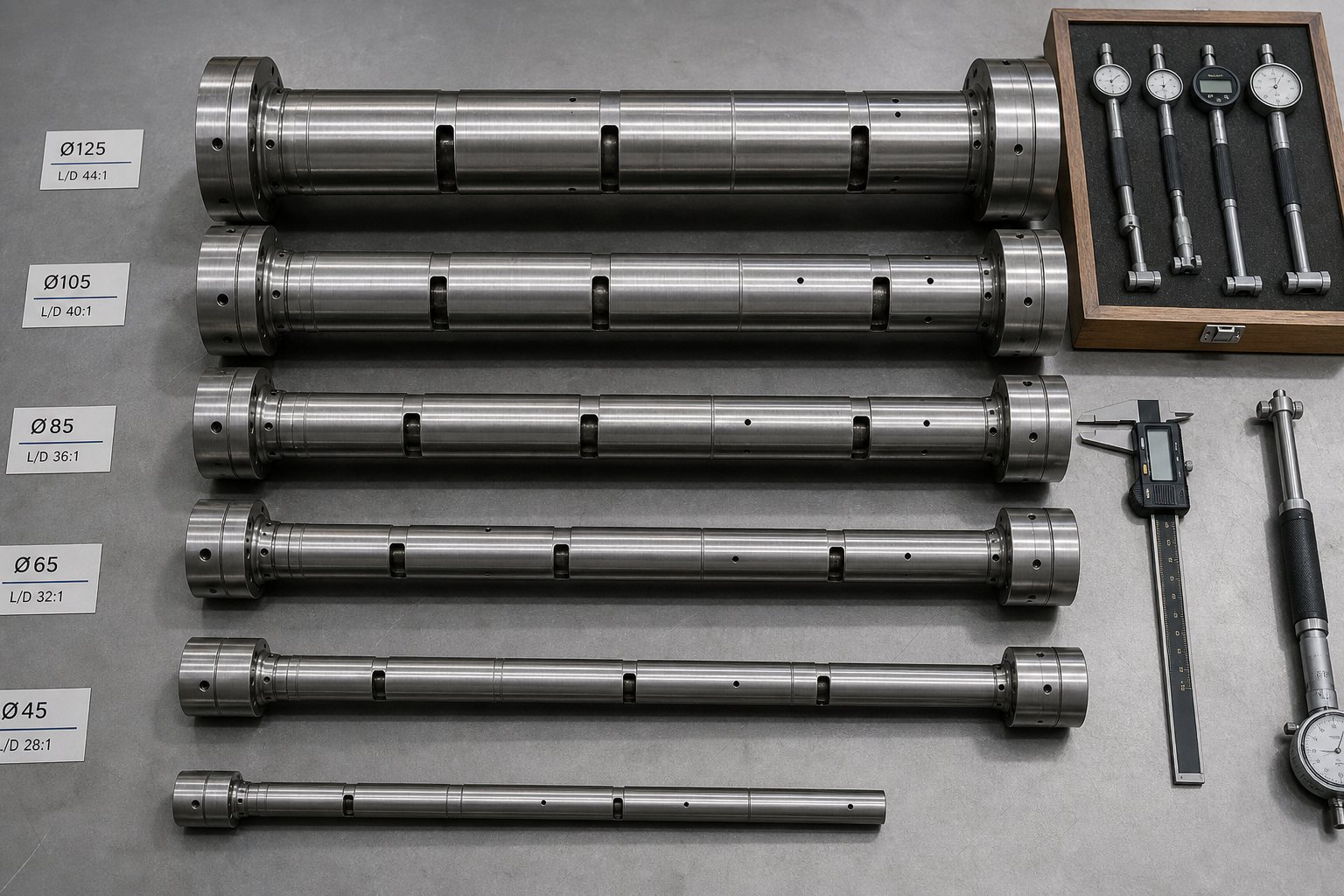
- Throughput requirements. Target output rate drives bore diameter and L/D ratio selection. Larger bore diameters accommodate higher volumetric throughput, while longer L/D ratios - 40:1 to 48:1 on modern twin screw extruders - provide additional processing zones for complex formulations requiring extended mixing, multiple vent stages, or downstream side-feeding. A laboratory twin screw extruder with a 20 mm bore might process 5 to 20 kg/hr for formulation development, while a production-scale twin screw extruder machine with a 92 mm bore handles 500 to 2,000 kg/hr for full commercial compounding.
- Process requirements. Does your application need vacuum degassing? Side-feeding of fillers or fibers? Liquid injection of peroxides or coupling agents? Each requirement dictates specific barrel segment types at specific positions along the extruder. A twin screw compounding extruder producing color masterbatch might need only a simple closed-barrel configuration with a single atmospheric vent. A reactive extrusion process for grafting maleic anhydride onto polyolefins might require liquid-injection barrels, multiple vacuum vents, and extended mixing sections - a fundamentally different modular layout on the same machine platform.
- Extruder architecture. Co-rotating parallel machines dominate compounding and offer the greatest barrel modularity. Counter-rotating conical designs serve PVC and shear-sensitive applications with different bore geometry requirements. A double screw extruder machine in a counter-rotating configuration uses tapered barrel sections that aren't interchangeable between positions - a constraint that limits reconfiguration flexibility but suits dedicated production lines processing a narrow range of formulations.
Understanding the Total Cost of Barrel Ownership
The invoice price of a barrel represents just the beginning. As Plastics Technology's analysis emphasizes, the true cost of ownership includes the working life of the barrel, the quality of the inlay composition, dimensional precision, and even how the barrel was handled during shipping. A lower-priced barrel with inconsistent bimetallic liner thickness or poor concentricity can wear out in half the time of a premium alternative - doubling your effective per-hour cost and forcing an additional unplanned changeover that disrupts production.
The economics break down along a clear pattern: investing in higher-grade metallurgy raises upfront cost but dramatically reduces replacement frequency. A bimetallic barrel for a double screw extruder processing mineral-filled compounds might cost 40 to 60% more than a nitrided steel barrel of identical dimensions, yet last three to four times longer under the same operating conditions. Over a five-year horizon, the bimetallic option costs less per operating hour - and that calculation doesn't even account for the production losses, labor, and alignment work involved in each barrel changeover.
Maintenance practices multiply these differences. A well-maintained barrel - with regular cooling channel descaling, calibrated thermocouples, proper bolt torque, and documented bore measurements - consistently delivers 30 to 50% more service hours than an identical barrel on a neglected machine. The barrel doesn't exist in isolation; it exists within a maintenance ecosystem that either protects or undermines its potential.
Matching Barrel Specifications to Your Processing Application
With these variables mapped, the selection process becomes a matching exercise. For operations running compounding, pelletizing, or recycling applications - where barrel wear rates are inherently high and reliable sourcing is essential - evaluating multiple suppliers against your specific requirements is the responsible approach. Look for manufacturers who offer the full metallurgy range, documented dimensional inspection data, and the application expertise to recommend configurations tailored to your process chemistry and throughput targets.
NANHAIYA's parallel twin screw barrel line is worth evaluating in this context, particularly for compounding producers, masterbatch manufacturers, and recycling plants that need replacement or custom barrels engineered for high-wear conditions. Their product range supports stable conveying, effective mixing, and resistance to the abrasive and corrosive demands that define these applications - the exact performance characteristics that determine whether a twin-screw extruder barrel earns its keep or becomes a recurring replacement expense.
Ultimately, the right barrel isn't the cheapest one or the most expensive one. It's the one whose bore diameter, metallurgy, modular configuration, and manufacturing quality align precisely with what your process demands - and that continues to deliver that alignment year after year because you built the maintenance program to support it.
Frequently Asked Questions About Twin Screw Extruder Barrels
1. What are the different types of twin screw extruder barrel segments?
Twin screw extruder barrels use five main modular segment types: closed barrels for full containment and temperature control, open-top feed barrels for material intake, vented or degassing barrels for removing moisture and volatiles, side-feed barrels for downstream addition of fillers or fibers via a twin-screw stuffer, and liquid-injection barrels fitted with pressurized nozzle ports for introducing oils, peroxides, or colorants. Each segment bolts together in a deliberate sequence that mirrors the processing stages from feeding through metering, and swapping or rearranging segments lets processors reconfigure the same machine for entirely different applications.
2. How do you know when a twin screw extruder barrel needs replacement?
Key warning signs include rising melt temperature despite stable barrel setpoints, declining output at constant screw speed, increasing motor current draw beyond 15% above baseline, visible scoring or galling on the bore surface during inspection, and material leakage at barrel segment joints. Quantitative confirmation requires bore gauge measurements at one-inch increments along the barrel length. Industry thresholds generally call for replacement evaluation when total bore diameter growth exceeds 0.15 to 0.20 mm above the original nominal dimension or when the annual bore ID increase exceeds 0.10 mm. Suppliers like NANHAIYA offer parallel twin screw barrels engineered for high-wear compounding and recycling applications, making replacement sourcing more straightforward.
3. What barrel material is best for processing abrasive or corrosive polymers?
Material selection depends on the dominant wear mechanism. For abrasive compounds containing glass fiber, calcium carbonate, or talc, iron-based bimetallic liners with hardness ratings of 60 to 72 HRC provide strong resistance. For corrosive resins like PVC or fluoropolymers that release acidic degradation byproducts, nickel-based bimetallic liners are the standard specification, reducing corrosive wear rates by five to eight times compared to nitrided steel. The most demanding applications combining high filler loading with corrosive chemistry benefit from HVOF tungsten carbide coatings, specifically WC-CrC-NiCr formulations that deliver hardness above 1,000 HV alongside strong chemical resistance.
4. Why is barrel-to-screw element matching important in twin screw extrusion?
Every barrel segment type requires a specific screw element geometry beneath it to function correctly. An open feed barrel needs large-pitch conveying elements to pull material away from the throat and prevent bridging. A vented barrel must sit above reverse-flight elements that create a low-pressure zone for volatile extraction. A side-feed barrel requires a starved conveying zone so incoming filler has space to enter the melt stream. Mismatches cause serious processing failures, including vent flooding when molten polymer exits through vent ports, feed bridging when restrictive elements choke intake, and stuffer backup when side-feed zones are fully filled. Correct pairing ensures each unit operation along the extruder performs as designed.
5. How does barrel bore geometry affect twin screw extruder performance?
The barrel bore sets the dimensional framework within which every screw element operates. The figure-eight bore profile is machined to tolerances within 0.01 to 0.03 mm of nominal diameter, creating flight clearances of roughly 0.1 to 0.2 mm per side. These clearances directly control self-wiping efficiency, shear rate distribution for dispersive mixing, and leakage flow over screw flight tips. As the bore wears and clearances widen, self-cleaning action degrades, peak shear rates in the flight-tip zone drop, and pumping efficiency decreases. This means a perfectly designed screw inside a worn barrel will underperform a simpler screw inside a tight, well-maintained bore, making regular bore measurement essential to sustained process quality.
Written by
Nanhaiya Technical Team
Zhoushan Nanhaiya Plastic Machinery Co., Ltd.
The Nanhaiya technical team supports screw and barrel manufacturing projects through application review, technical communication, custom manufacturing coordination, and production and quality control.
Discuss Your Application
Related Articles
More insights on screw barrel technology and plastics processing.

Extruder Machine Decoded: From Raw Pellet To Finished Product
Oct 6, 2026
Learn how an extruder machine works, compare single-screw vs. twin-screw types, and get expert guidance on specs, troubleshooting, and selection.
Read Article
PE Pipe Making Machine Decoded: From Raw Resin to Flawless Pipe
Oct 4, 2026
Learn how a PE pipe making machine works, from resin to finished pipe. Covers components, material grades, automation, troubleshooting, and buyer selection tips.
Read Article
PVC Profile Making Machine Decoded: From Raw Resin To Profit
Oct 3, 2026
Learn how a PVC profile making machine works — extrusion process steps, key technical parameters, die design, calibration methods, maintenance, and total cost of ownership.
Read ArticleLooking for something else?
Search by material, symptom or product and jump straight to the relevant page.
These are navigation suggestions based on keyword matching — not a quotation, not a delivery commitment, and not a substitute for engineering review. Final specification is confirmed by our engineers against your drawings and processed material.
Need help with screw barrel selection?
Share your machine model, processed material and application. Our team can help with pricing and technical support.