

What Is a Twin Screw Extruder Barrel and Why It Matters
Ask a room of process engineers what makes a twin screw extruder so versatile, and you'll hear about screw elements, kneading blocks, and modular screw configurations. Rarely does anyone lead with the barrel. Yet the barrel is the foundation on which every screw element performs — and when it underperforms, the entire process suffers.
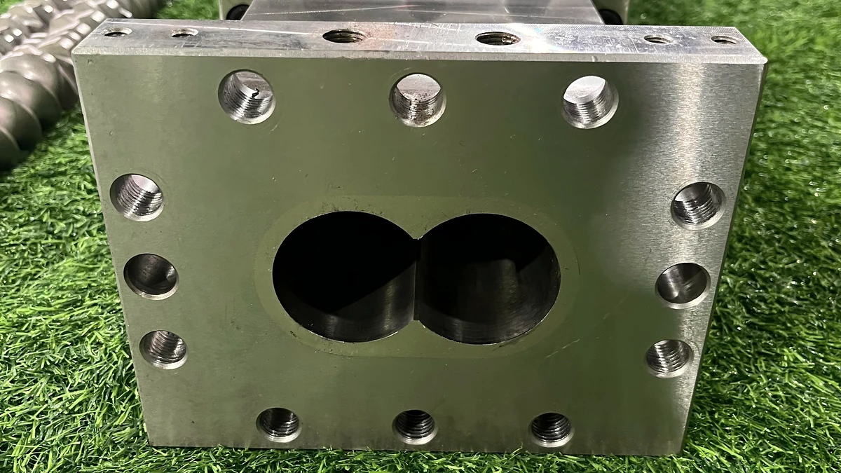
A twin screw extruder barrel is the precision-bored, temperature-controlled steel housing that encases two intermeshing screws within a characteristic figure-eight bore profile. It serves as the primary structure for heat transfer, pressure containment, material feeding, venting, and wear resistance — making it an active process element rather than a passive containment vessel.
That definition matters because it reframes how engineers should think about this component. The barrel isn't simply a shell that holds screws in place. It is the thermal backbone, the structural pressure boundary, and the interface through which raw materials enter and volatiles escape. Every compounding outcome — from dispersion quality to pellet consistency — traces back to barrel design decisions.
Defining the Twin Screw Extruder Barrel
Imagine slicing through a twin screw barrel at any point along its length. What you'll see is a distinctive figure-eight cross-section: two overlapping circular bores whose centers are separated by a fixed distance known as the centerline spacing. This geometry isn't decorative — it's dictated by the intermeshing relationship between the two screws housed inside.
In a co-rotating twin screw extruder, both screws turn in the same direction within this shared bore profile. The overlapping zone between the two bores is where material transfers from one screw flight to the next, creating the self-wiping action that prevents stagnation and keeps residence time distribution tight. In counter-rotating configurations, the screws turn in opposite directions, generating a calendering effect at the intermeshing region that favors gentler, compressive mixing. Either way, the barrel's internal geometry must match the screw profile with extreme precision — bore diameter, overlap region, and surface finish all work together to define how material flows, mixes, and exits.
This interdependence is critical. You can't evaluate a twin screw barrel in isolation from the screws it houses, and you can't optimize screw performance without understanding the barrel that surrounds them. The two are inseparable halves of a single processing system.
Why the Barrel Deserves Dedicated Attention
Most technical resources treat the extruder screw barrel as a supporting detail — a few sentences buried inside broader extruder overviews. That leaves engineers, maintenance teams, and procurement professionals without the focused guidance they need. Here's what the barrel actually controls:
- Thermal management: Each barrel segment provides independent heating and cooling, giving engineers zone-by-zone temperature control from the feed throat to the die.
- Pressure containment: The barrel walls withstand the internal pressures generated during melting, mixing, and metering — pressures that can be substantial in high-viscosity or reactive applications.
- Feeding and venting access: Open barrel sections with top ports or side-stuffer connections determine where materials enter and where moisture, air, and volatiles escape. As Plastics Technology notes, the proper sequencing of barrel sections along with corresponding screw elements allows a broad range of process specialization.
- Wear surface: The barrel bore is the first line of defense against abrasive fillers, corrosive polymers, and metal-to-metal contact — and its condition directly determines component lifespan and replacement cost.
This article is built entirely around the barrel. Every section that follows digs into a dimension of barrel engineering that typical extruder guides skip — from bore geometry and metallurgy to wear diagnostics and full lifecycle management. Whether you're specifying a new twin screw and barrel set, troubleshooting premature wear, or evaluating suppliers for replacement segments, you'll find the technical depth here that scattered overviews simply don't provide.
The logical starting point? Understanding how barrel construction itself has evolved — from rigid, single-piece housings to the modular segmented systems that give today's compounders their processing flexibility.
How Barrel Design Evolved From One-Piece to Modular Systems
That processing flexibility engineers enjoy today — swapping barrel segments, repositioning feed ports, adding vacuum vents mid-process — didn't exist in early twin screw extrusion. The first generation of extruder barrels were single, continuous steel housings machined from one block of metal. They were strong, simple, and remarkably inflexible. Understanding why the industry moved away from them reveals a lot about what modern barrel design actually solves.
Early Monolithic Barrel Construction
Picture a single steel cylinder, bored end-to-end with the figure-eight profile, drilled with heating and cooling channels, and bolted directly to the gearbox housing. That's a monolithic extruder barrel. It offered real structural advantages: uninterrupted rigidity along its full length, no segment-to-segment joints to leak or misalign, and straightforward manufacturing for shops equipped with deep-hole boring capability.
The problems, however, showed up in everyday operation. If wear concentrated in one section — say, near the feed zone where dry abrasive fillers first contact the bore — the entire barrel had to be removed and replaced. Lead times stretched into weeks or months. Costs were substantial because you were paying for a full-length precision-bored component even if only a few inches of the bore had degraded. Maintenance access to the screws meant pulling the whole barrel assembly, and reconfiguring port locations for a different formulation required machining modifications to the existing barrel or ordering an entirely new one.
Despite these drawbacks, monolithic barrels haven't disappeared entirely. Certain niche applications — small-diameter laboratory extruders, some counter-rotating designs, and systems processing a single product with minimal changeover requirements — still use one-piece construction where rigidity and simplicity outweigh configurability. But for the compounding and processing world at large, the limitations became untenable as product portfolios diversified and downtime costs climbed.
The Shift to Segmented Modular Barrels
The solution that reshaped the industry was deceptively simple in concept: divide the barrel into individual segments, each typically four to six diameters long, that bolt together in sequence to form the complete process section. Each segment carries its own independently controlled heating and cooling zones, and — critically — each segment can be designed with a specific process function in mind.
In practice, this means a process engineer can build an extruder barrel configuration almost like assembling building blocks. As Plastics Technology explains, a twin-screw extruder can be viewed as a series of unit operations that can be arranged as needed to optimize the process — and segmented barrels are what make that arrangement physically possible. A typical compounding line might use a feed barrel in position one, several closed barrel segments for melting and mixing, a side-feed barrel at position four or five for downstream filler addition, more closed segments for continued dispersive mixing, a vacuum vent barrel near the discharge end, and a final closed barrel before the die.
The operational benefits are significant. When an extruder feed barrel segment wears from continuous contact with dry pellets or abrasive powders, you replace that one segment — not the entire barrel set. When a new formulation requires an additional venting stage or a relocated side-stuffer port, you reconfigure the barrel layout rather than ordering custom machining. For multi-product facilities running different compounds on the same line, this configurability translates directly into reduced changeover time and lower capital expenditure per product.
Each segment also provides precise thermal control. Because every section has independent heater bands and cooling channels, engineers can build nuanced temperature profiles — cooler at the feed end to prevent premature melting, progressively hotter through the melting and mixing zones, and fine-tuned at the metering end to hit target melt temperatures. Closed barrel sections fully encase the melt on all sides, maximizing heat transfer surface area, while open sections sacrifice some thermal coverage for the functional access they provide.
Here's how the two design philosophies compare across the criteria that matter most to process engineers and maintenance teams:
| Criteria | Monolithic (One-Piece) Barrel | Segmented Modular Barrel |
|---|---|---|
| Configurability | Fixed layout; port changes require machining | Fully reconfigurable; segments can be rearranged or swapped |
| Maintenance Cost | High — full barrel replacement even for localized wear | Lower — replace only worn segments individually |
| Replacement Lead Time | Long — entire barrel must be manufactured and bored | Shorter — individual segments are stocked or produced faster |
| Structural Rigidity | Excellent — no joints along barrel length | Very good — properly torqued segment joints provide adequate rigidity |
| Multi-Product Suitability | Poor — limited to one configuration | Excellent — barrel layout adapts to different formulation demands |
For most compounding, reactive extrusion, and devolatilization applications, the modular segmented barrel extruder design has become the standard. The flexibility it provides isn't a luxury — it's a prerequisite for operations that need to respond to changing formulations, tightening quality standards, and pressure to reduce unplanned downtime.
Split Barrel and Clamshell Variants
A third category of extrusion barrels pushes accessibility even further. Split-barrel — sometimes called clamshell — designs divide the barrel horizontally rather than axially. The upper half hinges or lifts away from the lower half, exposing the screws along their full length without any disassembly of the barrel segments themselves.
Imagine needing to inspect screw element condition, clean residual material from the bore after a color changeover, or verify that a new screw configuration is properly seated. With a solid segmented barrel, that means pulling the screws out from the gearbox end — a time-consuming process, especially on larger machines. A clamshell design eliminates that step entirely: open the barrel, and the screws are right there.
The trade-off is mechanical. Split barrels introduce a horizontal parting line that reduces the structural rigidity of the barrel cross-section. The clamping mechanism that holds the two halves together must withstand internal process pressures without allowing the bore geometry to distort — and at high pressures or with aggressive screw configurations, this can become a limiting factor. Sealing at the parting line also demands careful maintenance to prevent leaks, particularly in vacuum devolatilization zones where even small air ingress compromises volatile removal.
For this reason, clamshell barrels are most commonly found on laboratory and pilot-scale extruders where frequent screw changes, rapid cleaning, and visual inspection are daily requirements. Production-scale compounding lines overwhelmingly favor solid segmented barrels, accepting the longer screw-removal procedure in exchange for superior pressure containment and bore integrity over extended production campaigns.
Barrel construction — whether monolithic, segmented, or split — defines what's physically possible. But construction alone doesn't determine process performance. That depends heavily on what's happening inside the bore: the precise dimensional relationships between barrel bore geometry, screw outer diameter, and the clearances that govern mixing efficiency and self-wiping behavior.
Barrel Bore Geometry and Critical Dimensional Relationships
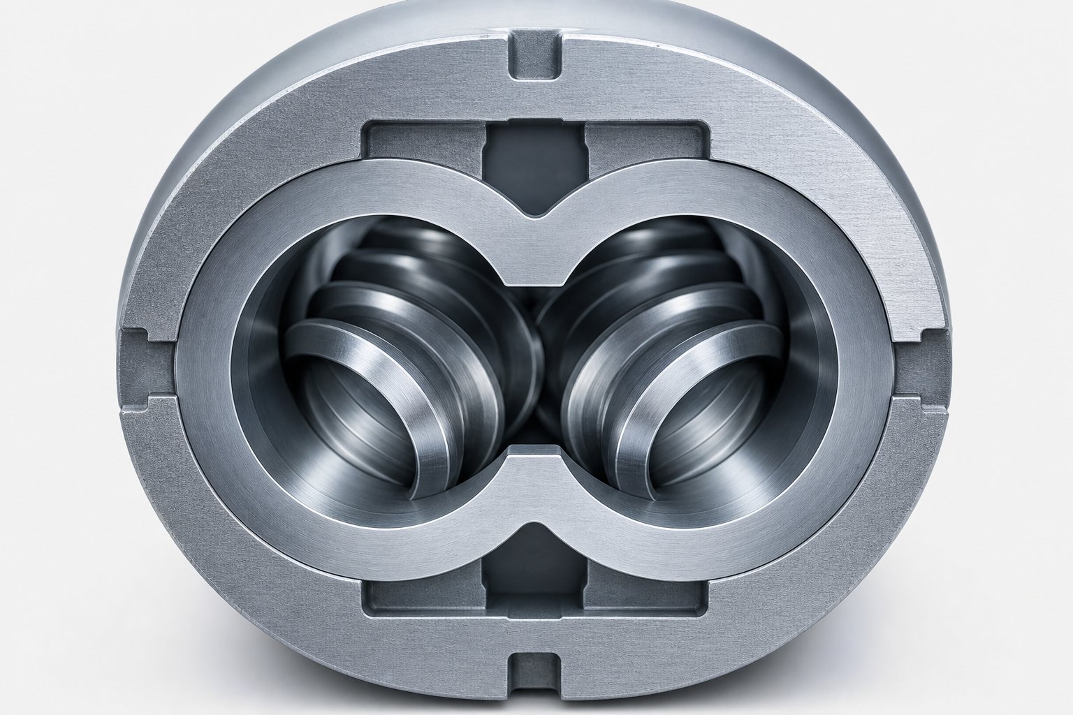
Three numbers — screw outer diameter, screw inner diameter, and the distance between shaft centers — define every functional characteristic of the twin screw extruder barrel's bore. Yet most barrel specifications stop at listing these values without explaining what they actually control. The dimensional relationships encoded in that figure-eight cross-section determine throughput capacity, torque limits, mixing intensity, and even how quickly the barrel wears. Understanding them transforms barrel selection from catalog shopping into genuine process engineering.
The Figure-Eight Bore Profile Explained
Slice through any twin screw extruder barrel and you'll see two overlapping circular bores. Each bore accommodates one extruder screw, and the overlap zone — sometimes called the intermeshing region — is where material transfers between the two screws. Three parameters define this cross-section completely:
- Screw outer diameter (Do): The outermost tip-to-tip diameter of the screw flight, which matches the bore diameter of the barrel.
- Screw inner diameter (Di): The root diameter at the base of the screw channel, measured at the screw shaft core.
- Centerline distance (a): The fixed spacing between the two bore centers, which determines the degree of overlap and the geometry of the intermeshing zone.
Of these, the Do/Di ratio is the single most consequential design parameter for process performance. It governs the depth of the screw channels relative to the overall screw diameter — and channel depth, in turn, controls free volume, shear rates, and the torque that can be transmitted through the shaft.
A higher Do/Di ratio means deeper channels. Deeper channels increase the free volume available for material conveyance, which generally translates into higher throughput potential and lower average shear rates in partially filled zones. As Xtrutech's comparative analysis demonstrates, Do/Di = 1.8 geometry provides roughly 40% more free volume and approximately 18% greater theoretical solids conveying capacity than Do/Di = 1.55 geometry at equivalent screw diameters.
A lower Do/Di ratio, by contrast, yields shallower channels but leaves more cross-sectional area for the torque-transmitting shaft. This produces a stiffer screw geometry capable of handling higher mechanical loads — a decisive advantage when processing high-viscosity engineering thermoplastics that demand substantial specific energy input.
Here's how the most common Do/Di ratios map to general application suitability:
- Do/Di = 1.25 to 1.35: Shallow channels, maximum shaft diameter, highest torque capacity. Suited for high-torque reactive extrusion and processing of very high-viscosity polymers where power input is the limiting factor.
- Do/Di = 1.45 to 1.55: Moderate channel depth with strong torque capacity. A versatile geometry widely used in co rotating twin screw extruder platforms for general-purpose compounding, engineering plastics, and applications requiring a balance between throughput and energy input.
- Do/Di = 1.65 to 1.80: Deep channels, large free volume, reduced average shear. Favored for high-throughput compounding, thermally sensitive materials, powder coating extrusion, and applications where gentle processing and high volumetric intake are priorities.
The practical implication is direct: selecting a barrel and extrusion screw combination with the wrong Do/Di ratio for your application constrains performance before you even start optimizing screw element configuration. A high-torque reactive process paired with a high-Do/Di barrel will hit shaft torque limits prematurely. A high-throughput mineral-filled compounding line on a low-Do/Di platform will be intake-limited, leaving available motor power underutilized.
There's a subtlety worth noting here as well. The Do/Di ratio also influences mixing character. Higher-ratio geometries generate greater volumes of elongational flow — the stretching and compressing action as material cycles through varying channel depths between intermeshing twin screws. Elongational flows are significantly more effective at droplet breakup and filler dispersion than shear flows alone, often by a factor of two or more. So the bore geometry you choose doesn't just set throughput boundaries — it shapes the fundamental mixing mechanisms your process relies on.
Understanding Barrel L/D Ratio and Its Process Impact
If Do/Di ratio defines what happens in cross-section, the length-to-diameter ratio defines what happens along the barrel's length. L/D is the single most referenced barrel specification in equipment selection, and for good reason: it determines how many distinct process functions — feeding, melting, mixing, venting, pressure buildup — can be physically arranged in sequence.
The concept is straightforward. Take the total working length of the barrel (from the feed opening to the discharge end) and divide it by the bore diameter. A barrel with 960 mm of process length and a 40 mm bore diameter has an L/D of 24:1. Extend that same barrel with additional segments to 1,600 mm and the L/D becomes 40:1.
What changes with that extra length is residence time, zone count, and process flexibility. A longer barrel gives material more time under controlled temperature and shear conditions. It also provides physical space for additional functional zones — a second venting stage, an extra mixing section, or a dedicated pressure-building zone before the die. For compounding extruders, L/D ratios typically range from 20:1 to 40:1, with the specific choice driven by application demands:
- L/D 20:1 to 28:1: Shorter process sections suitable for simple blending tasks, color concentrate let-downs, or materials that are sensitive to prolonged heat exposure. Fewer available zones, so the process must accomplish melting, mixing, and pressure buildup in a compressed sequence.
- L/D 32:1 to 36:1: The most common range for general-purpose compounding — enough length to accommodate feeding, melting, one or two mixing zones, a devolatilization stage, and a metering section. Balances residence time control with capital cost.
- L/D 40:1 and above: Extended barrels for complex processes that demand multiple devolatilization stages, downstream side feeding of multiple filler streams, reactive extrusion requiring extended reaction time, or applications combining several unit operations in a single pass. These longer configurations are standard in co rotating and counter rotating twin screw extruder platforms designed for maximum process versatility.
Keep in mind that a longer L/D ratio doesn't automatically improve results. Every additional barrel segment adds cost, requires more energy to heat and drive, and increases total residence time — which can be detrimental for thermally sensitive polymers. Materials prone to degradation at elevated temperatures may demand shorter barrels with aggressive screw designs that accomplish mixing quickly rather than relying on extended dwell time. The L/D ratio must be matched to the material's processing window, not selected on the assumption that longer is always better.
How Bore Dimensions Drive Screw-Barrel Clearance
With the bore profile and barrel length established, one final dimensional relationship completes the picture: the radial clearance between the extruder screw flight tips and the barrel bore wall. This gap — typically measured in hundredths of a millimeter — is surprisingly consequential for process performance.
Tight clearances serve three critical functions. First, they enable the self-wiping action that makes intermeshing twin screws so effective. As each screw flight sweeps past the barrel wall and through the intermeshing zone, minimal clearance means material is continuously scraped forward rather than allowed to stagnate. Stagnant material degrades, discolors, and eventually contaminates the product stream. Second, tight clearances improve mixing efficiency by forcing material through high-shear zones at the flight tips, generating localized intensive mixing that complements the distributive mixing occurring in the bulk channel flow. Third, controlled clearances prevent excessive back-leakage of pressurized melt over the screw flights, maintaining the pressure gradients that drive material forward through the barrel.
Typical clearance values scale with screw diameter. For smaller extruder screws in the 25-45 mm range, radial clearances of 0.08 to 0.12 mm are common. Larger machines in the 90-150 mm range may run clearances of 0.12 to 0.25 mm. These values reflect manufacturing precision capabilities and the need to accommodate thermal expansion during operation — both the barrel bore and the screw elements expand as they reach processing temperatures, and the clearance at ambient temperature must account for that differential growth.
Here's what makes clearance particularly important from a barrel engineering perspective: as the bore wears and its diameter grows, clearances increase progressively. That increase is not linear in its effects. A small amount of bore enlargement may have negligible process impact, but beyond a threshold — typically when clearance has roughly doubled from original specifications — self-wiping deteriorates noticeably, leakage flow increases, mixing efficiency drops, and specific energy consumption rises as the extruder screw works harder to maintain throughput against increased back-flow.
This degradation pattern is precisely why bore geometry isn't just a specification to record at installation — it's a living dimension that must be monitored throughout the barrel's service life. And the rate at which that dimension changes depends heavily on what's happening at the material-metal interface: the wear mechanisms driven by fillers, polymers, and operating conditions that gradually reshape the bore from the inside out.
Barrel Metallurgy and Wear-Resistant Liner Technologies
Bore geometry determines how material flows through the barrel. But what determines how long the barrel survives that flow? The answer is metallurgy. The alloys, liners, and surface treatments selected for a twin screw extruder barrel dictate whether the precisely machined bore dimensions you just specified hold tolerance for months — or years. Despite its direct impact on uptime and replacement cost, barrel metallurgy is one of the least discussed topics in extruder engineering. That gap is worth closing.
Base Barrel Materials and Their Properties
Every barrel starts with a base material — the structural steel body that provides mechanical strength, dimensional stability, and thermal conductivity. Two families dominate the landscape: nitriding steels and tool steels.
Nitriding steels, most commonly 38CrMoAlA, account for the majority of barrels in general-purpose screw extrusion. The steel is first quenched and tempered to a core hardness of roughly 28-32 HRC, then subjected to gas or ion nitriding. Nitrogen atoms diffuse into the surface and react with aluminum in the alloy to form aluminum nitride compounds, producing a surface hardness of HV 900-1020 — impressive on paper, but confined to a layer only 0.5-0.8 mm thick. For an extruder for polymer applications involving unfilled or lightly filled resins such as PE, PP, PS, and standard ABS, nitrided barrels offer excellent dimensional stability at a competitive price point. They're the workhorse of the industry for a reason.
The limitation reveals itself under harsher conditions. Once abrasive fillers or corrosive melt byproducts erode through that thin hardened layer, the softer base material underneath wears at an accelerating rate. There's no second line of defense.
Tool steels and through-hardened alloys take a different approach. Materials like D2, H13, and the CPM (Crucible Particle Metallurgy) series — including CPM 9V and CPM 10V — are hardened uniformly throughout their cross-section. CPM steels are manufactured using Hot Isostatic Pressing (HIP), which consolidates metal powder under extreme temperature and pressure to achieve a carbide distribution far more uniform than conventional casting can produce. The result is a barrel body with HRC 58-62 hardness from bore surface to outer wall. This through-hardened approach eliminates the thin-layer vulnerability of nitrided designs and is reserved for the most mechanically demanding polymer extruder applications — high-viscosity engineering plastics, heavily glass-filled compounds, and scenarios where maximum wear life justifies substantially higher material cost.
Wear-Resistant Liner Technologies
For many processing environments, neither a nitrided surface nor a through-hardened body alone provides the optimal solution. Instead, the industry relies on wear-resistant liners — thick alloy layers bonded to the inside of a tough steel barrel body. This bimetallic approach separates two distinct engineering functions: the base body handles structural loads and thermal conductivity, while the liner handles the abuse happening at the bore surface.
Three major liner categories cover the range of performance demands:
- Bimetallic centrifugal-cast liners: Molten alloy — iron-based, nickel-based, or cobalt-based — is spun inside the barrel bore at high speed, forming a metallurgically bonded liner typically 1.5-2.5 mm thick. Nickel-based alloys like Colmonoy 56 (HRC 50-55) deliver excellent combined wear and corrosion resistance, especially in PVC and chemically aggressive environments. Iron-based alloys with high chromium content target abrasive wear specifically.
- Powder-metallurgy HIP liners: Vanadium carbide-rich PM steel liners, consolidated under hot isostatic pressing, achieve hardness levels of HRC 65-68 and are designed for extreme abrasion scenarios — ceramic-filled compounds, wood-plastic composites, and stone-plastic composite (SPC) formulations where centrifugal-cast liners wear too quickly.
- Tungsten carbide and ceramic-based coatings: Applied via HVOF (High Velocity Oxygen Fuel) spraying or similar thermal spray processes, these coatings reach HV 1200-1400 and target the most severe abrasion-corrosion combinations. The coating bonds mechanically and metallurgically to the substrate, providing an extremely hard, dense wear surface.
Which liner is right? That depends entirely on your dominant wear mechanism. Here's how they compare:
| Liner Type | Typical Hardness | Corrosion Resistance | Abrasion Resistance | Thermal Conductivity | Relative Cost |
|---|---|---|---|---|---|
| Bimetallic — Iron-Based (High-Cr) | HRC 58-65 | Moderate | High | Good | Moderate |
| Bimetallic — Nickel-Based (e.g., Colmonoy 56) | HRC 50-55 | Excellent | Moderate-High | Good | Moderate-High |
| Powder Metallurgy HIP (Vanadium Carbide) | HRC 65-68 | Moderate | Very High | Moderate | High |
| Tungsten Carbide / HVOF Coating | HV 1200-1400 | Good-Excellent | Extreme | Lower | Very High |
| Nitrided Steel (Baseline) | HV 900-1020 | Low-Moderate | Moderate (thin layer) | Very Good | Low |
A critical point often overlooked: selecting the hardest available liner isn't automatically the best decision. Hardness fights abrasion, but it does nothing against chemical corrosion — and in some cases, extremely hard but brittle liners can crack under thermal cycling or mechanical shock. The liner must match the specific challenge your process presents.
Matching Barrel Material to Processing Challenge
So how do you connect metallurgy to your actual production floor? Start with the material you're processing. Different polymers and fillers impose fundamentally different types of barrel wear, and the right liner is the one that addresses your dominant degradation mechanism — not the one with the most impressive hardness number.
Consider glass-fiber-reinforced engineering plastics — PA6, PA66, PBT, or a polyester extruder application processing PET compounds with 30-50% glass content. Glass fibers are extremely abrasive, with hardness values that rival or exceed many steel alloys. They scour the bore relentlessly during screw extrusion, especially in mixing and metering zones. These applications demand high-hardness liners: bimetallic centrifugal-cast iron-based alloys at minimum, with PM HIP or tungsten carbide liners for the highest filler loads.
Corrosive processing presents a completely different challenge. PVC, CPVC, and fluoropolymers release hydrochloric acid (HCl) or hydrofluoric acid (HF) during thermal processing. Halogenated flame retardants generate similar acidic byproducts. Standard steel — no matter how hard — pits and corrodes under this chemical attack. These environments require nickel-based alloys like Colmonoy 56 or, for extreme corrosion, Hastelloy C-276 or Inconel 625 liners specifically engineered for acid resistance.
Pharmaceutical and food-grade extrusion adds a regulatory dimension. Here, the barrel material must satisfy contact-surface requirements that prioritize cleanability and non-contamination over raw wear resistance. Specific stainless steel grades — typically 316L or equivalent — may be mandated regardless of mechanical performance, because the compliance requirement supersedes the wear optimization.
The following mapping connects common processing scenarios to their recommended barrel material categories:
- Unfilled or lightly filled polyolefins (PE, PP): Standard nitrided 38CrMoAlA — cost-effective, adequate wear life.
- Glass-fiber reinforced nylons and polyesters (15-30% GF): Bimetallic centrifugal-cast iron-based liner with high chromium content.
- Heavily glass-filled engineering plastics (30-50% GF): PM HIP liner or tungsten carbide coating for maximum abrasion resistance.
- Mineral fillers — calcium carbonate, talc, barium sulfate: Bimetallic iron-based liner; severity depends on filler particle hardness and loading level.
- PVC, CPVC, and halogenated flame retardant compounds: Nickel-based bimetallic liner (Colmonoy 56 or equivalent); Hastelloy or Inconel for extreme cases.
- Fluoropolymers (PVDF, PTFE compounds): Hastelloy C-276 or Inconel 625 liners — standard nickel alloys may be insufficient against HF attack.
- Food-grade and pharmaceutical extrusion: 316L stainless steel or equivalent, selected for regulatory compliance and cleanability.
- Recycled plastics with unknown contamination: Bimetallic nickel-based liner providing combined abrasion and corrosion protection against unpredictable feedstock composition.
Getting this match right at the specification stage avoids costly mismatches later — a highly wear-resistant but corrosion-vulnerable liner failing prematurely in a PVC line, or a corrosion-resistant but soft liner eroding rapidly under mineral filler loads. The metallurgy defines the barrel's service ceiling. Everything above that ceiling — temperature zoning, port configuration, process optimization — builds on the assumption that the bore surface can survive long enough to make those efforts worthwhile.
Temperature Zoning, Venting, and Port Configurations
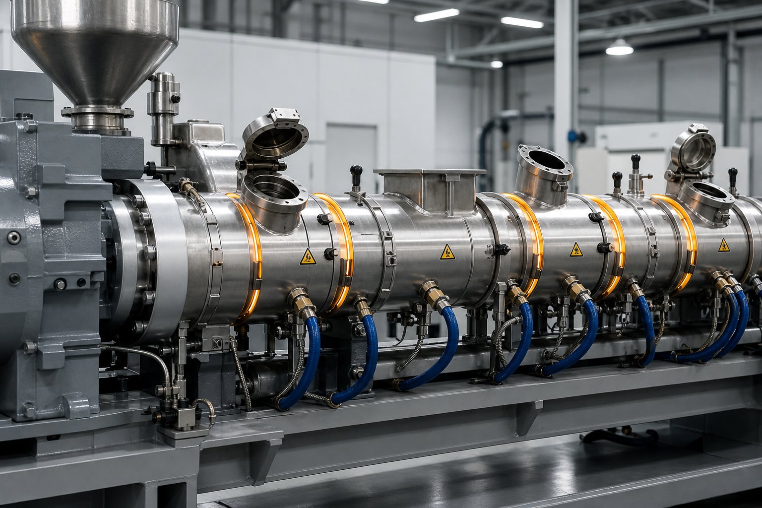
A barrel's metallurgy keeps the bore intact. But metallurgy alone doesn't make the barrel a processing tool — temperature infrastructure and strategically placed openings do. Every modern twin screw extruder barrel is designed with two interlocking systems built directly into its structure: independently controlled thermal zones that regulate heat flow into and out of the melt, and precisely located ports that allow materials in and volatiles out. Together, these systems transform a static steel housing into an active participant in every phase of compounding.
Temperature Zoning Strategy and Zone Profiling
Picture a twin screw extruder machine with eight barrel segments bolted in sequence. Each segment carries its own electric heater bands wrapped around the exterior and internal cooling channels — typically bored passages through which water or oil circulates. A dedicated thermocouple embedded in each segment feeds temperature data back to a controller. The result is eight individually adjustable thermal zones, each capable of heating, cooling, or holding a specific setpoint independently of its neighbors.
Why does this matter? Because the polymer passing through each zone is in a fundamentally different state. Near the feed throat, it's still solid — pellets, flakes, or powder. In the melting zone, it's transitioning from solid to liquid under intense shear. Through the mixing zones, it's fully molten and absorbing fillers. Near the discharge end, it's being metered under pressure toward the die. Each of these stages demands a different thermal environment, and the barrel's zone-by-zone control makes that possible.
The relationship between barrel temperature, screw speed, and throughput rate adds complexity. Higher screw speeds generate more viscous dissipation — frictional heat from shearing the polymer — which can push actual melt temperatures above barrel setpoints. Increasing throughput rate reduces the residence time in each zone, meaning the barrel has less time to influence melt temperature. As extrusion process research emphasizes, the set temperature displayed on a controller often does not correspond to the actual melt temperature, since the real mass temperature is usually higher than the adjusted setpoints. An intentional negative correction can be useful in certain cases to compensate for viscous heating.
Building a temperature profile from scratch for a compounding extruder application follows a logical sequence. Here's a general step-by-step approach for establishing your initial settings:
- Identify critical material temperatures: Determine the polymer's glass transition temperature (for amorphous resins), crystalline melting temperature (for semi-crystalline resins), and the manufacturer's recommended processing temperature range. These three values anchor your entire profile.
- Set the feed zone temperature well below the softening point: Typical values for standard thermoplastics fall between 20°C and 60°C. Keeping this zone cool prevents premature melting, which can cause pellets to bridge across the screw flights and block material conveyance. External water cooling on the feed barrel segment is standard practice.
- Set Zone 1 (immediately after the feed section) above the melting or softening temperature: This zone initiates the solid-to-melt transition. A practical rule of thumb — set it slightly above the crystalline melting point to maximize the motor's dissipation power contribution to melting.
- Interpolate middle zones toward the target processing temperature: Select either a rising profile (gradual increase from Zone 1 to the final zone), a constant profile (uniform temperature across all middle zones), or a peaked profile that rises above the target in the mixing zones and then drops back down toward the metering section. Rising profiles are the most common starting point for general compounding.
- Set the final zone and die temperature to the target processing temperature: For semi-crystalline polymers, this is typically 50°C to 75°C above the crystalline melting point. For amorphous polymers, approximately 100°C above the glass transition temperature serves as a reasonable starting point.
- Run the process, measure actual melt temperature at the die, and adjust: Compare the measured melt temperature against your target. If viscous heating is pushing melt temperatures too high, reduce barrel setpoints in the mixing zones. If the melt is too cold, raise middle zone temperatures or reduce throughput rate until the profile stabilizes.
This initial profile is a starting point, not a destination. Process optimization — adjusting individual zones based on observed melt quality, motor load, and product properties — can take hours of careful iteration. Changes propagate slowly through the system, sometimes requiring 30 minutes or more before their full effect becomes visible. That sluggish response is precisely why so many operators leave temperature profiles untouched after initial setup, even when hidden optimization potential exists.
Barrel Venting and Devolatilization Ports
Temperature zones control energy flow. Vent ports control mass flow — specifically, the removal of moisture, trapped air, residual monomers, and volatile degradation products that would otherwise remain trapped in the melt and compromise finished product quality.
Two types of vent ports serve this purpose, each suited to different severity levels of volatile removal:
- Atmospheric (open) vent ports: These are simply barrel openings exposed to ambient pressure. Gases and steam escape naturally as the partially filled screw channels pass beneath the opening. They're effective for removing entrained air during feeding and surface moisture from hygroscopic resins, but their driving force is limited to whatever vapor pressure the volatiles generate at melt temperature.
- Vacuum vent ports: Connected to a vacuum pump, these ports create a pressure differential that dramatically increases the driving force for volatile removal. As devolatilization process research confirms, each vacuum vent stage can reduce volatile concentration by approximately one order of magnitude. A triple-vented compounding twin screw extruder can bring a high-volatiles feedstock down to less than 0.1% residuals with proper design.
The barrel engineering behind venting is more involved than just cutting a hole in a segment. Vent barrel sections feature enlarged openings — wider than standard barrel ports — to maximize the vapor escape path. The screw elements beneath the vent must be partially filled and conveying, never fully filled, to prevent polymer from being pushed up into the vent opening.
This is where vent stuffers enter the picture. During vacuum devolatilization, the pressure differential can pull molten polymer upward into the vent — a problem called vent flooding. Vent stuffer barrels incorporate a pair of small counter-rotating screws positioned directly in the vent opening. These screws continuously push any polymer attempting to escape back down into the main bore while allowing vapor to pass freely through the gap between the stuffer screws. The result is stable vacuum operation even at high throughput rates where the risk of flooding is greatest.
Proper seal design on either side of the vent is equally critical. Reverse or neutral screw elements upstream and downstream of the vent zone create filled-channel seals that isolate the low-pressure vent region from the higher-pressure zones adjacent to it. Without these seals, vacuum would pull through the screw channels and disrupt feeding upstream or pressure buildup downstream.
Side Feeding and Downstream Injection Ports
If vent ports let things out, side feed ports let things in — and where along the barrel you introduce materials matters enormously for product quality. This is especially true for twin screw compounding extruder operations handling fiber-reinforced plastics, mineral-filled compounds, or formulations requiring liquid additive injection.
A side feeder — also called a side stuffer — consists of a hopper and a pair of conveying screws that push solid materials directly into the molten polymer through a dedicated barrel opening. The barrel segment providing this access, often called a combination (combi) barrel, includes both the side-feeder opening and a vent port to allow entrained air within the incoming solids to escape. Without that air vent, trapped air would pressurize the barrel and blow powder or fibers back out of the feeder.
Why not simply feed everything at the main feed throat? Because the melting zone subjects all incoming materials to the highest shear forces in the entire process. Fibers that pass through the melting section get ground into fragments, destroying the length-to-diameter aspect ratio that gives them their reinforcing value. Glass, carbon, and mineral fibers are therefore fed downstream — after the polymer is fully molten — so they encounter only the gentler dispersive mixing of narrow-disc kneading blocks rather than the aggressive shearing of the melting zone. Feed location directly controls fiber length retention and, consequently, the mechanical properties of the final compound.
Mineral fillers like calcium carbonate, talc, and barium sulfate follow similar logic for different reasons. Introducing high filler loads at the feed throat can overwhelm the conveying capacity of the feed zone, interfere with melting, and expose the feed-section barrel bore to maximum abrasive contact. Downstream side feeding after full polymer melting allows the filler to be wetted and dispersed into an already-fluid matrix, improving dispersion quality while reducing wear in the feed section.
Liquid additives — plasticizers, coupling agents, colorant dispersions, reactive agents — bypass the side feeder entirely and are pumped directly into the melt through injection ports drilled into barrel segments or dedicated injection plates. The injection point must be positioned where the screw elements are conveying (not fully pressurized), and the pump pressure must exceed the local melt pressure to prevent polymer from backing up into the injector nozzle.
The strategic takeaway is this: the barrel's port configuration determines the sequence and location of every material interaction in your process. Relocating a side feeder by even one barrel segment changes filler residence time, affects the mixing intensity applied to incoming solids, and alters the thermal history of the compound. These are not minor adjustments — they are fundamental process design decisions encoded in barrel hardware.
Temperature zones, vent ports, and feed openings collectively define the barrel's active processing capability. But all of that capability degrades over time as the bore surface wears. Understanding exactly how, where, and why that wear occurs — and how to detect it before it undermines your process — is the next critical layer of barrel knowledge most engineers underestimate.
Barrel Wear Mechanisms and Diagnostic Strategies
Every barrel specification, liner selection, and temperature profile discussed so far assumes the bore is in good condition. In reality, bore condition degrades from the first hour of production — and the rate, pattern, and type of degradation depend on variables that most engineers only consider after a problem surfaces. Barrel wear is the single largest driver of unplanned downtime and replacement cost in twin screw extrusion. Yet it remains one of the least systematically managed aspects of extruder operation.
Understanding wear isn't just about knowing when to order new parts. It's about recognizing which mechanism is destroying your bore, where along the barrel it's happening fastest, and what you can change — in materials, alignment, or operating practice — to extend service life before the next replacement cycle.
Primary Barrel Wear Mechanisms
Three dominant wear modes account for virtually all bore degradation in extruder screws and barrels. Each leaves a distinctive signature on the bore surface, and each demands a different countermeasure. Treating them interchangeably — or worse, ignoring the distinction entirely — leads to mismatched liner selections and premature failures.
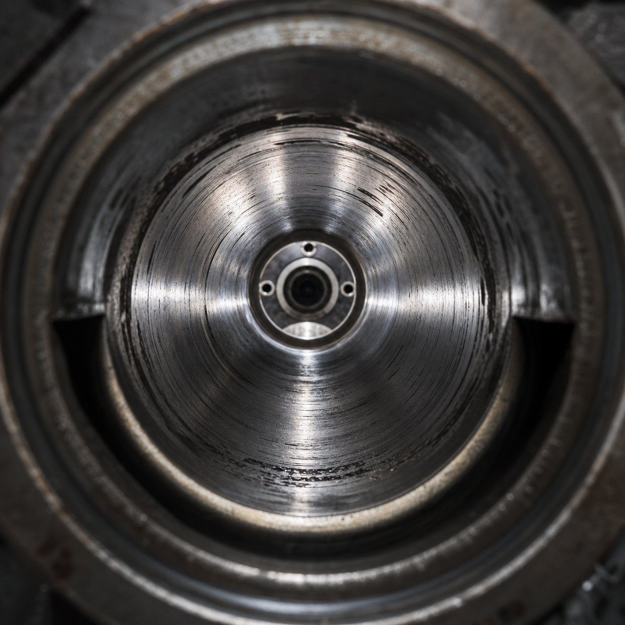
Abrasive wear is the most common mechanism in compounding operations. Hard filler particles — glass fibers, mineral powders, pigments — act like microscopic cutting tools, progressively eroding the bore surface as the screw extruder conveys material under pressure. The severity depends on filler hardness, particle shape, loading percentage, and screw speed. As Xtrutech's wear analysis notes, abrasive wear is dependent on the amount of material being produced rather than the time the extruder has been in operation — meaning high-throughput lines accumulate wear disproportionately faster than their runtime hours might suggest. Visually, abrasive wear rounds off sharp machined edges on screw elements and polishes bore surfaces to a smooth, eroded finish.
Not all fillers are equally destructive. The following list ranks common abrasive fillers by their relative hardness and barrel wear impact, from most to least aggressive:
- Glass fiber (Mohs ~6.5): Extremely abrasive; the leading cause of premature bore enlargement in reinforced engineering plastic compounding. Fiber ends act as cutting points under shear.
- Titanium dioxide — TiO2 (Mohs ~6.0-6.5): Highly abrasive despite its fine particle size; a major wear contributor in masterbatch and white concentrate production.
- Silica / glass beads (Mohs ~5.5-7): Hardness varies by grade; some silica fillers rival glass fiber in destructiveness.
- Wollastonite (Mohs ~4.5-5): Needle-like particle shape increases effective abrasion beyond what its moderate hardness suggests.
- Calcium carbonate — CaCO3 (Mohs ~3): Relatively soft, but at high loadings (60-80%) the sheer volume of particles creates significant cumulative wear.
- Talc (Mohs ~1-1.5): Low hardness, but platelet geometry and typical high loading levels still produce measurable long-term bore enlargement.
- Carbon black (Mohs ~1-2): Minimal abrasive impact; wear in carbon black operations is rarely filler-driven.
Corrosive wear attacks the bore through chemical reaction rather than mechanical erosion. When PVC, CPVC, PVDF, or polymers containing halogenated flame retardants are processed at elevated temperatures, they release acidic byproducts — hydrochloric acid (HCl), hydrofluoric acid (HF), and other aggressive species — that pit and dissolve unprotected steel surfaces. Corrosion manifests as dimpled or pitted bore surfaces, distinctly different from the smooth, polished appearance of abrasive wear. Even in non-corrosive polymer families, condensation forming on chilled barrel sections can trigger localized corrosion if cooling water temperatures dip below the dew point.
Adhesive wear — metal-to-metal contact between the plastic extruder screw flight tips and the barrel bore wall — is often the most mechanically destructive of the three. It occurs when screw shafts deflect under load and press against the barrel wall, or when unbalanced high-pressure zones in the screw channel push the screw laterally with enormous force. The result is score marks on the bore wall and flattened, galled screw flight tips. This type of wear is particularly insidious because, as industry analysis confirms, screws in a twin screw extruder are rigidly fixed at the gearbox end and supported primarily by the molten resin during production. When extruder screws rotate at high speed without sufficient material fill — during startup, shutdown, or between production runs — that resin support vanishes and the unsupported shaft ends can deflect into the bore.
Wear Patterns Along the Barrel Length
If you measured bore diameter at every point along a worn barrel, you wouldn't find uniform enlargement. Wear concentrates in specific zones, and knowing where to expect the worst damage tells you both where to look first during inspections and which barrel segments to prioritize for premium liner materials.
The feed zone takes disproportionate punishment. Incoming pellets, flakes, or dry powders are still solid and rigid — they haven't softened or melted yet. These hard particles are conveyed under pressure against the bore wall, generating intense abrasive contact. If the formulation includes mineral fillers or glass fibers introduced at the main feed throat, the feed section barrel bore encounters those abrasives at their most angular and destructive — before any rounding or wetting by molten polymer can blunt their edges. Feed zone barrels in heavily filled operations often show twice the bore enlargement of downstream segments over the same production period.
The mixing and kneading zones experience a different wear profile. Here, the screw configuration generates high shear and dispersive forces that create intense pressure differentials across the screw flights. As screw wear research explains, if melt is forced downstream while solids temporarily plug a channel, localized instantaneous pressures can spike to extreme levels — exceeding 10,000 psi in some cases. Since the channel is eight to nine times the width of the flight, the resulting lateral force on the screw can approach four to five times the nominal channel pressure. This creates combined abrasive and adhesive wear as the screw is momentarily driven into the barrel wall. The mixing zone signature is a combination of smooth abrasion tracks and localized scoring where metal-to-metal contact occurred.
The metering and discharge zones tend to show the least mechanical wear because the material is fully molten and acting as a hydrodynamic bearing between screw and barrel. However, these zones operate at the highest sustained temperatures in the barrel, which makes them vulnerable to corrosive attack from thermal degradation byproducts. Polymers that release acids, aldehydes, or other aggressive volatiles at elevated temperatures concentrate their chemical assault in these downstream sections. The pattern is subtle — pitting and surface roughening rather than dimensional enlargement — but it degrades heat transfer efficiency and can contaminate the product stream with metallic corrosion particles.
Diagnosing Barrel Wear and Setting Replacement Criteria
Sounds complex? The diagnostic approach is actually straightforward — provided you do it consistently. Bore gauging is the fundamental measurement technique: a precision inside micrometer or telescoping bore gauge is inserted at multiple positions along the barrel length, and the measured diameter is compared against the original specification.
For modular extruder screw and barrel systems, measurements should be taken at a minimum of three positions per segment — entry, midpoint, and exit — and at multiple angular orientations (typically 0° and 90°) to detect ovality from unidirectional wear. Record every measurement and track the trend over time. A bore that shows 0.03 mm of enlargement after six months of production is telling a very different story than one showing 0.15 mm over the same period.
When should you actually replace a worn segment? Industry practice from Plastics Technology documents several common thresholds: replacing when the flight clearance reaches four times the original specification, when the bimetallic liner is fully worn through, or when rate reduction and discharge temperature increase make continued operation uneconomical. Xtrutech's guidelines for twin screw extruders specify approximately 5% increase in bore starting diameter over a length of one screw diameter (1D) as the threshold for barrel liner replacement.
The economic trigger often arrives before the mechanical limit. You'll notice the signs in your process data: rising specific energy consumption (kWh per kilogram) as the extruder screws work harder to compensate for increased leakage flow, climbing melt temperatures as dissipated energy increases, and declining throughput at constant screw speed. Research from Dow demonstrates that for a 100-mm screw processing PE at constant rate, increasing the flight clearance from 0.005 in. to 0.016 in. raised discharge temperatures by approximately 10°C and could reduce achievable throughput by up to 13%. For operations where line capacity is fully committed, that 13% reduction directly translates to missed orders and lost revenue.
A practical tip: don't wait for process symptoms to trigger measurement. Establish a bore inspection schedule tied to production volume — measured in tons processed — rather than calendar time alone. Abrasive wear, as the reference data confirms, scales with material throughput, not runtime hours. A line running two shifts daily at maximum rate will reach its wear threshold far sooner than the same machine running one shift at moderate output.
Barrel Alignment and Its Role in Wear Prevention
Every wear mechanism discussed above is amplified — sometimes dramatically — by barrel misalignment. When modular barrel segments aren't precisely aligned along their shared centerline, the screw shafts are forced to deflect as they rotate through the misaligned bore. That deflection creates asymmetric loading: one side of the screw flight presses harder against the barrel wall while the opposite side pulls away. The result is accelerated, localized adhesive wear in a pattern that follows the misalignment — often appearing as a helical scoring pattern that spirals along the bore.
Barrel alignment is critical, especially for large-diameter and long extruders. Alignments should be performed whenever a barrel is removed or changed, if the foundation shifts, or if barrel supports shift. Even thermal effects can introduce misalignment: uneven heating from a faulty barrel heater causes asymmetric thermal expansion, warping the barrel axis and driving the screw into the bore wall on the overheated side.
Basic alignment verification during barrel assembly follows a logical sequence:
- Check flatness of mating faces: Every barrel segment mates face-to-face with its neighbor. Surface imperfections, burrs, or embedded debris at these joints tilt one segment relative to the next, introducing angular misalignment that compounds with each additional segment.
- Verify bore concentricity at joints: Use a precision straight edge or bore alignment tool inserted through adjacent segments to confirm that the figure-eight bore profile transitions smoothly from one segment to the next without steps or offsets at the joint.
- Inspect and lubricate support contacts: Front barrel supports that contact the barrel's outer diameter must be clean and well-lubricated with high-temperature silicone grease to allow the barrel to expand thermally without binding. Binding at a support point introduces a fixed deflection point that bends the entire barrel axis.
- Torque barrel bolts in the proper sequence: Segment-to-segment bolts should be tightened in a star pattern to even, manufacturer-specified torque values. Over-torquing one side or following an incorrect tightening sequence can warp the joint and introduce bore offset.
- Verify alignment under operating temperature: Thermal expansion changes the barrel's geometry. After initial heat-up to processing temperatures, recheck alignment at support points and confirm that the barrel has expanded uniformly without developing a bow or twist.
Think of alignment as the lowest-cost, highest-impact wear prevention measure available. No liner upgrade, no metallurgical improvement, and no screw design change can compensate for a barrel that forces the screws into its own wall every revolution. Getting the bore straight costs labor and attention — not capital — and yet misalignment remains one of the most frequently overlooked root causes of premature extruder screw and barrel failure.
Wear mechanisms explain how barrels degrade. Diagnostics tell you when degradation has gone too far. But the most impactful decisions happen earlier — at the design stage, when barrel features are matched to the specific demands of the application. Different processing challenges impose fundamentally different requirements on liner material, barrel length, port layout, and cooling strategy, and the next section maps those connections directly.
Matching Barrel Design to Your Processing Application
Specifications like L/D ratio, Do/Di geometry, and liner hardness only become meaningful when connected to what's actually happening inside the barrel — the polymer being melted, the fillers being dispersed, and the volatiles being stripped. Engineers who select barrels by matching numbers on a datasheet to numbers on a purchase order miss the point entirely. The barrel must be designed around the processing challenge, not the other way around.
Each application category imposes a distinct combination of abrasive, corrosive, thermal, and throughput demands. A barrel that excels in glass-fiber-reinforced nylon compounding would fail within months in a PVC line — and vice versa. The following breakdown maps the most common processing scenarios to the barrel features that determine success or premature failure.
High-Abrasion Compounding Applications
Imagine running 40% glass-fiber-reinforced PA66 through a twin screw extruder plastic compounding line at 800 kg/h. Every kilogram of output carries roughly 320 grams of glass fiber — angular, hard particles with a Mohs hardness around 6.5 — scraping against the bore with every screw revolution. This is the most punishing environment a barrel will face, and it demands a specific design response at every level.
Liner selection is non-negotiable: bimetallic centrifugal-cast iron-based alloys represent the minimum standard, with PM HIP (hot isostatic pressing) liners or tungsten carbide coatings reserved for the highest filler loads. As the wear data from the previous section illustrates, glass fiber is the single most destructive filler in compounding operations, and anything less than a high-hardness liner translates to unacceptably short barrel life.
Port geometry matters just as much. Fibers introduced at the main feed throat pass through the melting zone and get ground to powder — destroying the aspect ratio that gives them structural value. Downstream side-feeder ports allow fibers to enter after the polymer is fully molten, where they can be incorporated using gentle narrow-disc kneading blocks that preserve fiber length. The barrel must include a combi-barrel segment with both a side-stuffer opening and an air vent to release entrained gases from the incoming fiber stream.
L/D ratio selection for abrasive compounding typically falls in the 36:1 to 44:1 range. The barrel needs enough length to accommodate the main feed zone, a complete melting section, a downstream filler feed with dedicated mixing, at least one devolatilization stage, and a pressure-building metering section — all while keeping residence time short enough to avoid thermal degradation of the polymer matrix. Every additional second the abrasive-laden melt spends in the barrel accelerates bore wear. Suppliers engineering barrels for these multi-stage, high-wear scenarios — such as NANHAIYA's parallel twin screw barrel solutions designed for compounding and pelletizing lines — focus specifically on pairing premium liner materials with optimized segment configurations to balance wear life against processing flexibility.
Corrosive Polymer Processing
Corrosive applications flip the material challenge from mechanical to chemical. When processing PVC, CPVC, PVDF, or compounds containing halogenated flame retardants, the polymer itself becomes the aggressor. Thermal degradation releases hydrochloric acid (HCl) or hydrofluoric acid (HF) that attacks unprotected iron-based surfaces from the inside out — pitting the bore, undermining liner integrity, and eventually contaminating the product stream with metallic corrosion particles.
The barrel response starts with metallurgy: nickel-based bimetallic liners like Colmonoy 56 resist acid attack far more effectively than standard iron-chromium alloys. For fluoropolymer processing, where HF is particularly aggressive, Hastelloy C-276 or Inconel 625 liners may be the only viable options. Hardness is secondary here — corrosion resistance is the survival criterion.
Temperature zone strategy becomes a process safety tool in corrosive applications. PVC, for example, has a narrow window between its processing temperature and its degradation onset temperature. Barrel zones must be tightly controlled to keep the melt within that window, particularly in the mixing and metering sections where residence time and shear heating combine to push temperatures upward. A peaked temperature profile — where the mixing zone runs slightly hot for dispersion, followed by a deliberate temperature reduction in the metering zone — helps minimize acid release near the die end.
Venting configurations for corrosive processing serve double duty: removing volatile degradation byproducts protects both product quality and the barrel itself. Vacuum vent ports positioned downstream of the mixing zone strip HCl or other acidic volatiles before they can accumulate and accelerate bore corrosion. In many PVC compounding lines running on a double screw extruder, two-stage devolatilization — one atmospheric vent followed by one vacuum vent — is standard practice for this reason.
Recycling and Post-Consumer Resin Operations
Recycling operations are the wild card. Unlike virgin polymer compounding, where feedstock is consistent and well-characterized, post-consumer resin (PCR) streams arrive contaminated, variable in composition, and loaded with moisture. The barrel must be designed to handle all of these unknowns simultaneously — and tolerate surprises without catastrophic failure.
Feed zone cooling is the first priority. PCR flake and regrind tend to be irregular in shape, inconsistent in bulk density, and often arrive wet. Robust water cooling on the feed barrel segment prevents premature softening and agglomeration that would bridge the screw flights and starve the extruder. Higher-capacity cooling channels than those used in standard compounding barrels are often specified for recycling applications.
Multiple venting stages — often three or more across the barrel length — are essential. Moisture content in PCR feedstock can range from 0.5% to over 3%, and residual contaminants (adhesives, inks, food residue) generate volatile organic compounds during melting. Each vent stage reduces volatile concentration by roughly one order of magnitude. A double screw extruder machine configured for recycling might use an atmospheric vent in the early melting zone, followed by two vacuum vent stages downstream, to achieve the residual volatile levels demanded by food-contact or automotive specifications.
Liner selection for recycling applications presents a unique dilemma: the feedstock is unpredictable. One batch of PCR flake might contain abrasive paper label fragments; the next might include PVC contamination that releases corrosive HCl. Nickel-based bimetallic liners offering combined abrasion and corrosion protection represent the safest specification — sacrificing some peak abrasion resistance compared to PM HIP liners in exchange for chemical versatility that matches the reality of inconsistent recycled streams. Many recycling operators running a parallel twin screw extruder have found this balanced approach extends barrel service intervals significantly compared to single-mechanism liners.
Masterbatch and Color Concentrate Production
Masterbatch production, including color concentrates, white masterbatch with TiO2, and black masterbatch with carbon black, imposes a completely different set of barrel priorities. The dominant concern isn't wear life or corrosion resistance — it's contamination control and changeover speed. When you're switching from a deep blue concentrate to a bright yellow three times per shift, every trace of residual pigment left in the barrel becomes a quality defect in the next batch.
Self-wiping barrel geometries with tight screw-to-bore clearances are critical here. The intermeshing action of co-rotating twin screws in a properly maintained bore leaves minimal dead zones where pigment can accumulate and resist purging. Clamshell barrel designs simplify cleaning during color changeover by allowing the barrel to open along its horizontal plane, giving operators direct access to the bore surface and screw elements for manual cleaning. This access can reduce changeover time from hours to minutes on smaller twin screw plastic extruder lines dedicated to color concentrate production.
For larger production-scale masterbatch lines where split-barrel designs aren't structurally practical, easy-clean barrel configurations rely on polished bore finishes, minimal segment count to reduce joint crevices, and carefully designed screw profiles that leave no stagnation zones. L/D ratios for masterbatch typically range from 32:1 to 48:1 — the upper end reserved for formulations requiring extensive pigment dispersion, such as high-chroma organic pigments that demand significant shear energy to break down agglomerates. Standard masterbatch production uses L/D ratios between 32 and 48, with higher ratios providing additional mixing zones for complex formulations.
Feed system design also differs. Masterbatch formulations often combine polymer pellets with fine powders (pigments, additives) that have very different bulk densities and flow characteristics. The barrel's feed throat and initial conveying section must handle these mixed-density streams without segregation. A screw extruder granulator line producing masterbatch pellets may integrate gravimetric blenders directly above the feed throat for precise pigment dosing, and the feed barrel segment's geometry must accommodate the resulting varied bulk material flow.
The following table consolidates the barrel feature recommendations across all four application categories, providing a quick-reference guide for specification decisions:
| Application Type | Recommended Liner Material | Typical L/D Range | Port Configuration | Cooling Requirements | Key Barrel Priority |
|---|---|---|---|---|---|
| High-Abrasion Compounding (glass fiber, mineral fillers) | PM HIP or tungsten carbide for heavy loads; bimetallic iron-based (high-Cr) for moderate loads | 36:1 - 44:1 | Downstream side feeder + air vent (combi-barrel); 1-2 vacuum vents | Standard feed zone cooling; moderate mid-barrel cooling | Maximum abrasion resistance; fiber length preservation via downstream feeding |
| Corrosive Polymer Processing (PVC, PVDF, halogenated FR) | Nickel-based bimetallic (Colmonoy 56); Hastelloy C-276 or Inconel 625 for fluoropolymers | 32:1 - 40:1 | 1 atmospheric + 1-2 vacuum vents for volatile/acid removal | Tight zone control; reduced metering zone temps to limit degradation | Corrosion resistance; precise temperature management to minimize acid generation |
| Recycling / Post-Consumer Resin | Nickel-based bimetallic (combined abrasion + corrosion protection) | 36:1 - 48:1 | Multiple vents (3+): 1 atmospheric + 2 vacuum stages; optional side feeder for additives | Enhanced feed zone cooling for wet/variable feedstock; high-capacity cooling channels | Volatile removal capacity; tolerance for unpredictable contamination |
| Masterbatch / Color Concentrate | Standard nitrided or light bimetallic for unfilled carriers; iron-based for TiO2-heavy white MB | 32:1 - 48:1 | Main feed throat (premixed); optional side feeder for split-feed formulations | Standard cooling; emphasis on uniform zone temperatures for color consistency | Self-wiping geometry; easy-clean design; rapid changeover capability |
For operations spanning multiple application categories — a contract compounder running glass-filled nylons one week and recycled polyolefins the next, or a screw extruder granulator line switching between mineral-filled and color masterbatch grades — barrel versatility becomes the overriding specification priority. Modular barrel systems with interchangeable segments allow processors to swap liner types and port configurations between campaigns rather than compromising on a single barrel setup that underperforms in every application. Suppliers like NANHAIYA, which engineers parallel twin screw barrels specifically for compounding plants, pelletizing lines, masterbatch producers, and recycling operations, exemplify this multi-application design philosophy — building barrels that address the full spectrum of wear and process demands rather than optimizing for a single scenario.
Matching the barrel to the application is the most consequential specification decision an engineer makes. But the barrel doesn't operate in isolation. Its bore geometry, port locations, and liner material must work in concert with the screw profile, the drive system's torque capacity, and the downstream equipment receiving the extruder's output. That systems-level integration is where individual component quality either multiplies — or cancels out.
How Barrel Design Integrates With the Complete Extruder System
You can specify the perfect liner material, the ideal L/D ratio, and a port configuration tailored to your exact formulation — and still end up with mediocre results. Why? Because a twin screw extruder barrel never works alone. It operates as one element within a tightly coupled extruder system where barrel geometry, screw configuration, drive capacity, and downstream equipment must function as a single coordinated unit. Optimizing the barrel in isolation is like tuning a single instrument without listening to the rest of the orchestra.
Barrel and Screw Design Interdependence
Every barrel layout decision has a corresponding screw design consequence — and ignoring that link guarantees suboptimal performance. Consider a practical scenario: you add a vacuum vent barrel segment to improve devolatilization. That vent opening requires the screw elements beneath it to be partially filled and conveying forward. If you don't simultaneously replace the kneading blocks upstream of the vent with a restrictive element that creates a melt seal, vacuum will pull through the screw channels and destabilize feeding zones upstream. The barrel change demands a screw profile change.
The same interdependence applies to side-feeder locations. Relocating a side-stuffer port one segment downstream changes where fillers enter the melt stream, which alters the mixing length available for dispersion. The screw elements downstream of the new feed position must be reconfigured — typically adding distributive mixing elements — to compensate for the reduced mixing residence time. Barrel bore geometry, port locations, and liner material are never independent variables. They must be co-specified with the screw element configuration from the start.
Liner material selection connects to screw metallurgy as well. Running hardened tungsten carbide barrel liners against soft nitrided screw elements creates a hardness mismatch that accelerates screw wear. Conversely, pairing hard-coated screw elements with a softer barrel liner shifts the wear burden to the barrel — the more expensive component to replace. In well-designed twin-screw extruder systems, barrel and screw hardness are deliberately balanced so that the lower-cost, easier-to-replace component wears preferentially.
Drive System Torque and Barrel Specifications
The relationship between drive torque and barrel geometry is one of the most consequential — and most frequently overlooked — constraints in twin screw extruders. Here's how it works: the Do/Di ratio that defines the barrel's bore profile simultaneously determines how much cross-sectional area is available for the torque-transmitting screw shafts. A higher Do/Di ratio deepens the screw channels and increases free volume, but it also reduces shaft diameter. Smaller shafts transmit less torque before reaching their mechanical limit.
As Xtrutech's geometry comparison demonstrates, the Do/Di = 1.55 variant provides significantly greater shaft cross-section — and therefore higher torque capacity — than the Do/Di = 1.8 variant at the same nominal screw diameter. For high-energy processing applications like engineering thermoplastics, this difference is decisive: the twin-screw extruder machine is most frequently limited by the torque capacity of its screws, not by motor power or barrel volume.
What does this mean for barrel specification? You can't select a high-Do/Di barrel for its superior free volume without verifying that the drive system can deliver enough torque through the resulting thinner shafts to actually process your target material. A barrel optimized for throughput paired with a drive system that torque-limits at 60% of its rated speed is a costly mismatch. Conversely, specifying a low-Do/Di barrel for maximum torque capacity on a low-viscosity material wastes the available motor power — the extruder hits its volumetric intake limit long before the drive approaches its torque ceiling.
The practical takeaway: barrel Do/Di ratio, motor power, gearbox torque rating, and target material viscosity must be evaluated together. Changing any one of these parameters shifts the operating envelope of the entire twin-screw extruder, and the barrel specification must reflect that interdependence rather than being selected from a catalog in isolation.
Downstream Equipment Considerations
The barrel's job doesn't end at the last segment. Everything it produces — the melt temperature, discharge pressure, flow homogeneity, and volatile content — must match the requirements of whatever equipment sits downstream. A mismatch here creates bottlenecks, quality defects, or both.
Pelletizing systems are the most common downstream connection, and they impose specific demands on barrel output. Strand pelletizers require consistent melt viscosity and pressure to maintain uniform strand diameter. Underwater pelletizing systems demand tighter melt temperature control because the die plate temperature directly affects pellet shape and crystallization behavior. As integrated system research confirms, synchronizing extruder output with pelletizer speed is critical — and that synchronization depends on the barrel delivering stable, predictable melt characteristics at its discharge end.
Sheet and profile dies add another layer of complexity. These dies require high discharge pressures — often 50 to 150 bar — sustained uniformly across the die width. The barrel's metering zone length and screw configuration in the final segments must generate sufficient pressure without overheating the melt. A barrel that's too short in the metering section can't build adequate pressure; one that's too long subjects the melt to unnecessary residence time and thermal degradation.
Even the scale-up process itself reflects barrel-system interdependence. Research from Thermo Fisher Scientific highlights that when scaling from laboratory twin-screw extruders to production-scale machines, the barrel's available surface-to-volume ratio changes fundamentally — volume grows by a factor of three while surface area increases by only a factor of two. This means heating and cooling efficiency per unit of processed material decreases with increasing barrel diameter. A temperature profile that works perfectly on a lab-scale twin-screw extruder may produce unacceptable melt temperatures at production scale simply because the larger barrel can't remove viscous heat as effectively. The barrel specification must anticipate these scaling effects rather than assuming direct transferability.
Specifying a barrel without considering the complete system — screws, drive, and downstream equipment — leads to suboptimal performance regardless of individual component quality.
This systems-level perspective is what separates effective barrel engineering from component purchasing. The barrel is not the final specification — it's one node in a network of interdependent decisions. And managing that network across the barrel's full service life — from initial specification through procurement, installation, operation, and eventual replacement — demands a structured lifecycle approach that most operations lack.
Managing the Full Barrel Lifecycle From Specification to Replacement
A barrel that's perfectly designed for the application, properly integrated with the screw and drive system, and well-matched to downstream equipment still faces one unavoidable reality: it wears out. The difference between operations that manage this gracefully — with planned replacements, minimal surprises, and predictable costs — and those that lurch from one emergency shutdown to the next comes down to lifecycle management. From the moment a barrel is specified through its final replacement decision, every phase presents opportunities to protect uptime and control costs — or to introduce problems that compound over years of production.
Specification and Procurement Essentials
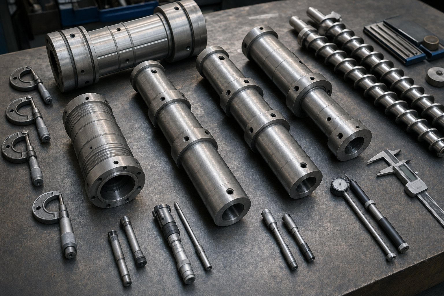
When you're ordering a new or replacement twin screw extruder barrel, the specification document is your single most important quality control tool. An incomplete spec leaves critical decisions to the supplier's default assumptions — assumptions that may not match your process requirements. A thorough spec eliminates ambiguity and gives you a concrete baseline for acceptance testing when the barrel arrives.
The following checklist presents the key parameters in priority order. Missing any of the top five virtually guarantees a mismatch; missing the lower items increases the risk of installation delays or suboptimal performance:
- Bore diameter and Do/Di ratio: These must match your existing screw element geometry exactly. Even 0.05 mm of bore diameter error changes clearances enough to affect self-wiping and mixing performance.
- L/D ratio and total segment count: Specify both the overall process length and the number of individual segments. A 40:1 barrel built from ten 4D segments is not interchangeable with one built from eight 5D segments — the bolt patterns, port locations, and zone boundaries differ.
- Segment configuration and sequence: Define which positions are closed barrels, which are feed barrels, which carry side-stuffer openings, and which provide atmospheric or vacuum vent ports. Include a barrel layout diagram showing the sequence from gearbox to die.
- Liner material grade: Specify the exact alloy — not just "bimetallic" or "wear-resistant." Request the alloy designation, target hardness range, and minimum liner thickness. Reference the application-to-material mapping from the metallurgy section to ensure your selection matches the dominant wear mechanism.
- Port locations, sizes, and orientations: Define feed port and vent port positions relative to barrel segment number, specify opening dimensions, and indicate whether ports are top-mounted, side-mounted, or at a specific clock position.
- Heating and cooling channel specifications: Specify heater band dimensions, wattage requirements per zone, cooling channel diameter and routing, and connection fitting sizes. Incompatible cooling connections can delay commissioning by weeks while adapters are fabricated.
- Surface finish requirements: For food-grade, pharmaceutical, or masterbatch applications, specify bore surface roughness (Ra value) and any polishing requirements.
- Documentation requirements: Request EN 10204 3.1 material certificates for base steel and liner alloy, hardness test reports at multiple bore locations, dimensional inspection records, and cooling channel pressure test certificates.
Twin screw extruder price varies enormously depending on liner material, segment count, and documentation requirements. A complete set of nitrided barrel segments for a 50 mm extruder might cost a fraction of what PM HIP-lined segments for a 92 mm machine would run. Getting the specification right before soliciting quotes prevents the most expensive procurement mistake: comparing prices across suppliers who are quoting fundamentally different barrel constructions because the spec left room for interpretation.
Installation, Alignment, and Commissioning
A precision-manufactured barrel can be ruined during installation. The assembly process for modular barrel segments demands methodical attention to alignment, torque, and leak integrity — rushing any step introduces problems that show up as accelerated wear, temperature inconsistencies, or cooling failures weeks or months later.
Start by inspecting every segment mating face for burrs, surface damage, or embedded debris. Even a small particle trapped between two segment faces introduces angular misalignment that compounds across the full barrel length. Clean each face with a lint-free cloth and verify flatness with a precision straight edge before assembly.
Bolt torquing follows a specific sequence — always a star or cross pattern, never sequential around the bolt circle. Apply torque in three progressive stages (typically 50%, 75%, then 100% of the manufacturer's specified final torque) to distribute clamping force evenly and prevent warping at the segment joint. Over-torquing is as damaging as under-torquing: it can distort the bore geometry at the joint, creating a step that the screw flight tips will strike every revolution.
After mechanical assembly, pressure-test every cooling channel before connecting to the plant water system. A hairline crack or a poorly sealed O-ring that leaks coolant into the bore during operation will contaminate the melt, corrode internal surfaces, and potentially cause steam explosions in the process section. Standard practice is pressurizing channels to 1.5 times the maximum operating water pressure and holding for a minimum of 15 minutes while inspecting for leaks.
The initial heat-up procedure matters more than most operators realize. Bring all barrel zones to processing temperature gradually — typically ramping at 30-50°C per hour — to allow thermal expansion to occur uniformly. Rapid heating creates thermal gradients that can warp barrel segments and stress segment-to-segment joints. Once at temperature, verify alignment at all support points and confirm that the barrel has expanded freely without binding against fixed structures.
Operational Monitoring and Preventive Maintenance
The barrel doesn't announce its deterioration with a warning light. Wear develops incrementally, and the process symptoms it produces — rising melt temperature, declining throughput, increasing specific energy — emerge so gradually that operators often attribute them to material variation or screw wear rather than bore degradation. A structured monitoring program catches these trends before they become production crises.
Periodic bore measurements form the backbone of any barrel maintenance strategy. As industry sourcing data confirms, dimensional inspection of bore diameter should occur every 1,500 to 2,000 operating hours as a baseline, with more frequent checks — every 800 to 1,200 hours — for barrels processing abrasive compounds above 30% filler loading. Use a telescoping bore gauge or precision inside micrometer at three positions per segment (entry, midpoint, exit) and at two angular orientations to detect ovality. Log every measurement so that trends, not isolated readings, drive your replacement decisions.
Beyond physical bore measurements, process data provides continuous indirect monitoring. Track these indicators at consistent operating conditions — same formulation, same screw speed, same throughput rate — to isolate barrel-related changes from other variables:
- Specific energy consumption (kWh/kg): Rising values at constant output signal increasing screw-barrel clearance and greater back-leakage of melt over worn flight tips. Documented studies show 6% to 12% increases in specific energy as clearance grows from 0.1 mm to 0.5 mm.
- Melt temperature stability: Wider temperature swings at the die indicate deteriorating mixing uniformity as clearance increases and self-wiping action weakens.
- Barrel zone heater duty cycles: A heater zone that suddenly runs at higher duty cycle than its neighbors may indicate a fouled or restricted cooling channel in that segment, reducing the zone's ability to reject heat.
- Cooling water flow rates and return temperatures: Declining flow or rising return temperature through a barrel segment's cooling channels signals scale buildup or partial blockage — problems that degrade temperature control long before they cause a visible failure.
- Throughput at constant screw speed: A declining specific rate (kg/h per RPM) is one of the earliest and most reliable indicators that bore wear is affecting pumping efficiency.
Establish a maintenance log — digital or paper — that records these values at fixed intervals. Practical maintenance guidance consistently emphasizes that a simple log with calipers, bore gauge, and consistent measurement locations catches wear trends early and converts reactive crisis management into planned maintenance events.
Replacement, Refurbishment, and Supplier Selection
Every barrel reaches a point where continued operation costs more than replacement. The question is whether that threshold calls for replacing individual segments, the full barrel set, or whether refurbishment can extend the current barrel's service life at lower cost.
Individual segment replacement makes economic sense when wear is concentrated — a feed zone barrel eroded by abrasive filler contact while downstream segments remain within tolerance. Replace the worn segment, verify alignment across the joint, and return to production. This is one of the core advantages of modular barrel construction, and it's why tracking bore measurements by segment is so valuable: the data tells you exactly which segments have reached their limits.
Full barrel set replacement is warranted when multiple segments approach their wear thresholds simultaneously, or when a process reconfiguration requires different port locations, additional vent stages, or a change in L/D ratio. For operations evaluating a twin screw extruder for sale on the used equipment market, verifying bore condition segment-by-segment is essential due diligence — purchasing a machine with a worn barrel set effectively adds the replacement cost to the acquisition price.
Barrel relining — boring out the worn liner and installing a new centrifugal-cast liner — can be cost-effective when the base barrel body remains structurally sound. Industry experience indicates refurbishment typically costs 40% to 60% of a new barrel segment's price and restores 85% to 95% of original service life. However, if the base material shows fatigue cracking, dimensional distortion, or cooling channel corrosion, relining is a false economy — the structural foundation won't support another service cycle.
Supplier selection is the final — and often most consequential — lifecycle decision. The twin screw extruder manufacturers who build the original equipment (OEMs like Coperion, Leistritz, KraussMaffei, and others) supply replacement barrels at OEM-quality standards but typically at premium pricing and longer lead times. Aftermarket manufacturers offering OEM-compatible barrels have become a significant part of the supply chain, with capable suppliers providing parts compatible with platforms from a Coperion extruder or Leistritz extruder line to Thermo Fisher extruder systems and CPM Century Extrusion equipment. The key is evaluating these suppliers rigorously rather than defaulting to the lowest twin screw extruder price on a quotation sheet.
When evaluating any twin-screw extruder manufacturer or aftermarket barrel supplier, prioritize these criteria:
- Durability and material certification: Does the supplier provide EN 10204 3.1 material certificates for both base steel and liner alloy? Can they document hardness at multiple bore locations and supply metallographic cross-sections verifying liner bond quality and carbide distribution?
- Application-specific engineering capability: Can the supplier's technical team recommend the correct liner material, port configuration, and segment layout for your specific polymer, filler type, and operating conditions — rather than offering a one-size-fits-all solution?
- Material processing expertise: Does the supplier understand the difference between specifying a barrel for glass-fiber-reinforced nylon versus PVC versus recycled polyolefin? Barrel engineering is not generic metalwork — it demands polymer processing knowledge.
- Vertical integration and manufacturing control: Which production steps — centrifugal casting, heat treatment, precision boring, final grinding — are performed in-house versus outsourced? As sourcing research emphasizes, each outsourced step introduces process control variability that shows up as inconsistent field life.
- Multi-application product range: Suppliers like NANHAIYA, which engineers parallel twin screw barrels specifically for compounding plants, pelletizing lines, masterbatch producers, and recycling operations, demonstrate the kind of application-spanning capability that gives procurement teams confidence the barrel is designed for their actual processing environment — not adapted from a generic catalog offering.
- Quality management certification: ISO 9001:2015 is the minimum baseline. For automotive or medical supply chains, IATF 16949 certification provides additional process control assurance.
- Lead time and inventory strategy: Does the supplier stock common segment sizes and liner grades for rapid delivery, or does every order start from raw material? For operations where unplanned downtime costs thousands of dollars per hour, lead time is a direct cost factor.
The barrel lifecycle — from specification through procurement, installation, operation, monitoring, and replacement — is ultimately a cost management discipline. Every decision at each phase either extends the productive life of the barrel or shortens it. Engineers who treat the barrel as a commodity to be purchased at the lowest price per segment inevitably pay more over a 36-month horizon than those who invest in correct specification, careful installation, systematic monitoring, and rigorous supplier qualification. The barrel may represent a small fraction of the total extruder's capital cost, but as the data throughout this article demonstrates, it governs a disproportionate share of the machine's operating economics — and deserves the engineering attention that reality demands.
Frequently Asked Questions About Twin Screw Extruder Barrels
1. What is the typical lifespan of a twin screw extruder barrel?
Barrel lifespan varies widely based on liner material, filler type, and throughput volume. A nitrided barrel processing unfilled polyolefins may last several years, while the same barrel running 40% glass-fiber-reinforced nylon could reach its wear limit within months. Industry practice recommends replacement when bore diameter enlarges by roughly 5% over a one-screw-diameter length, or when flight clearance reaches four times the original specification. Monitoring specific energy consumption and bore gauge measurements every 1,500 to 2,000 operating hours helps predict replacement timing before process quality suffers. Suppliers like NANHAIYA engineer parallel twin screw barrels with premium liner technologies specifically to extend service intervals in high-wear compounding, pelletizing, and recycling applications.
2. How do I choose the right barrel liner for my twin screw extruder?
Liner selection depends on matching the dominant wear mechanism in your process. For abrasive fillers like glass fiber or mineral powders, high-hardness bimetallic iron-based or PM HIP liners provide the best protection. Corrosive polymers such as PVC or fluoropolymers require nickel-based alloys like Colmonoy 56 or Hastelloy C-276 to resist acid attack. Recycling operations with unpredictable feedstock benefit from nickel-based liners offering combined abrasion and corrosion resistance. Food-grade and pharmaceutical extrusion typically mandates 316L stainless steel for regulatory compliance. Always specify the exact alloy designation and minimum liner thickness rather than accepting generic descriptions like 'wear-resistant' from your supplier.
3. What is the difference between monolithic and modular twin screw extruder barrels?
Monolithic barrels are single-piece steel housings bored end-to-end, offering maximum structural rigidity but limited flexibility. When wear occurs in one zone, the entire barrel must be replaced at significant cost and lead time. Modular barrels consist of individual segments bolted together in sequence, each with independent heating, cooling, and a specific process function such as feeding, venting, or closed conveying. This design lets engineers replace only worn segments, reconfigure port locations for different formulations, and adapt barrel layout without purchasing entirely new hardware. Modular systems dominate modern compounding because they reduce downtime, lower per-incident replacement cost, and support multi-product operations.
4. Why does barrel alignment matter for twin screw extruder performance?
Misaligned barrel segments force screw shafts to deflect as they rotate, creating asymmetric contact between flight tips and the bore wall. This accelerates adhesive wear in a distinctive helical scoring pattern and can double or triple the rate of bore enlargement compared to a properly aligned barrel. Even thermal effects from a faulty heater band can cause localized expansion that warps the barrel axis. Alignment verification should be performed whenever segments are reassembled, using precision straight edges at segment joints, proper star-pattern bolt torquing in progressive stages, and post-heat-up checks at operating temperature. It is the lowest-cost, highest-impact wear prevention measure available.
5. What L/D ratio should I select for my twin screw extruder barrel?
The ideal L/D ratio depends on process complexity. Simple blending or thermally sensitive materials suit shorter barrels in the 20:1 to 28:1 range. General-purpose compounding with one mixing zone and one devolatilization stage typically uses 32:1 to 36:1. Complex processes requiring multiple vent stages, downstream side feeding of fillers, or reactive extrusion benefit from 40:1 and above. Longer barrels provide more functional zones and residence time but also increase capital cost, energy consumption, and thermal exposure. The ratio must be matched to your material's processing window — longer is not automatically better, especially for degradation-sensitive polymers where excessive dwell time causes quality issues.
Written by
Nanhaiya Technical Team
Zhoushan Nanhaiya Plastic Machinery Co., Ltd.
The Nanhaiya technical team supports screw and barrel manufacturing projects through application review, technical communication, custom manufacturing coordination, and production and quality control.
Discuss Your Application
Related Articles
More insights on screw barrel technology and plastics processing.
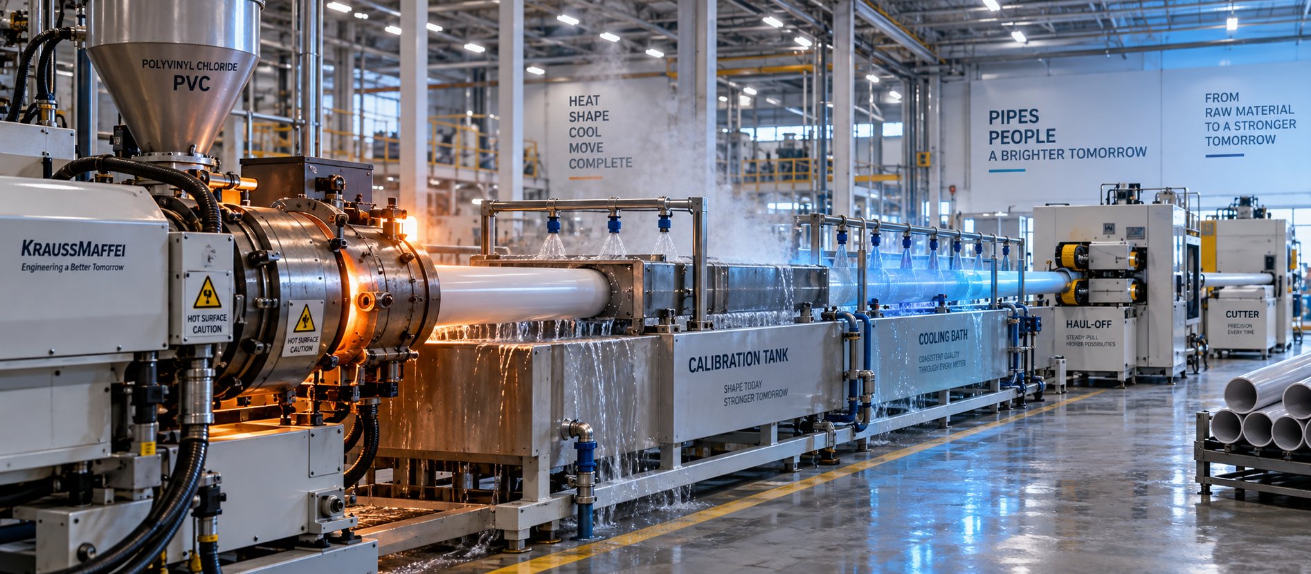
PVC Pipe Making Machine: What No Supplier Will Tell You First
Oct 21, 2026
Learn what a PVC pipe making machine really includes, how each component works, extruder types compared, maintenance schedules, defect fixes, and buying tips.
Read Article
What Your Film Extrusion Machine Datasheet Won't Tell You
Oct 20, 2026
Film extrusion machine guide covering blown vs cast processes, multilayer configurations, screw specs, resin selection, and supplier evaluation for production engineers.
Read Article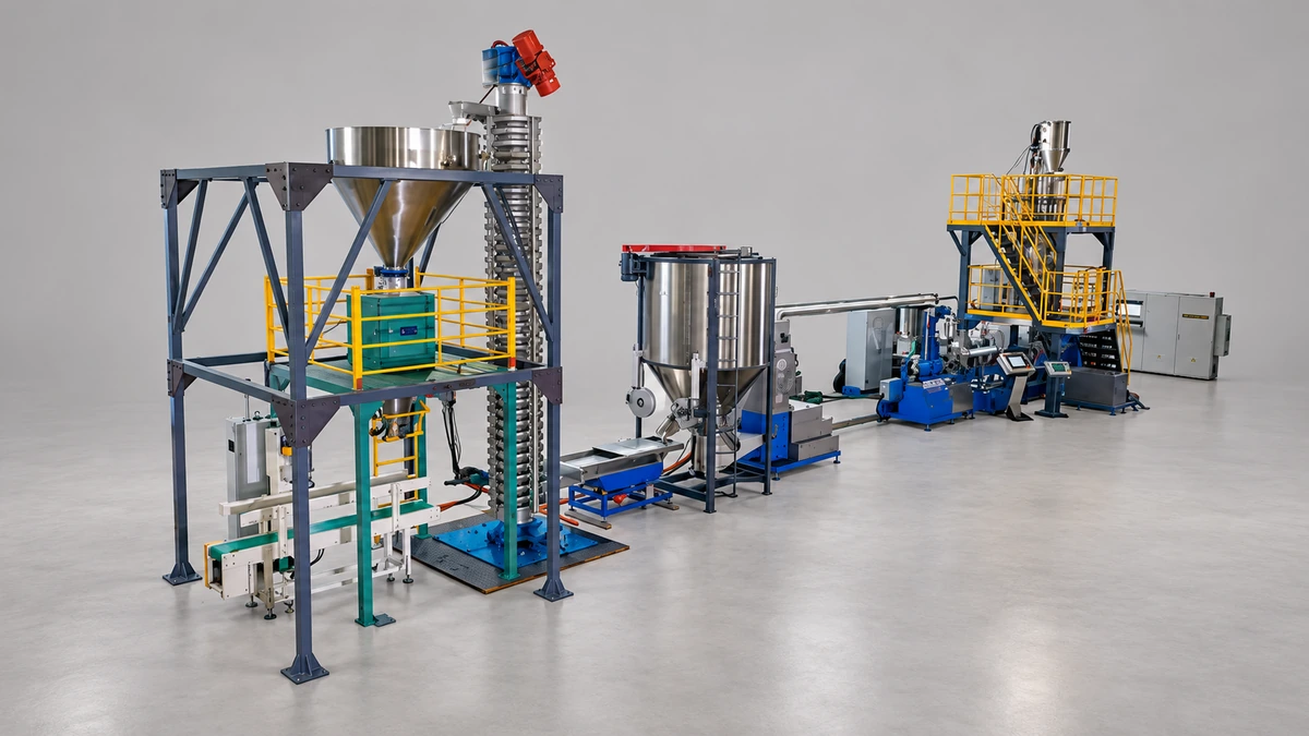
Raw Scrap to Perfect Pellets: Plastic Pelletizing Machine Guide
Oct 19, 2026
Learn how a plastic pelletizing machine converts scrap into uniform pellets. Covers cutting methods, extruder types, quality control, costs, and maintenance.
Read ArticleLooking for something else?
Search by material, symptom or product and jump straight to the relevant page.
These are navigation suggestions based on keyword matching — not a quotation, not a delivery commitment, and not a substitute for engineering review. Final specification is confirmed by our engineers against your drawings and processed material.
Need help with screw barrel selection?
Share your machine model, processed material and application. Our team can help with pricing and technical support.