

What a Twin Screw Extruder Animation Actually Reveals
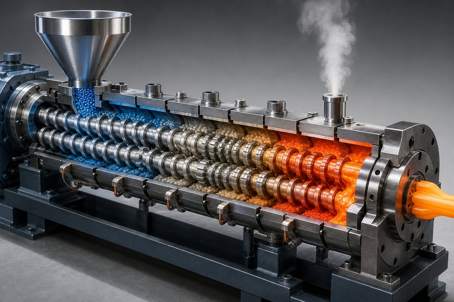
Imagine two helical screws spinning side by side inside a heated barrel. Polymer pellets tumble into the feed throat, get grabbed by interlocking flights, and begin a violent, transformative journey — squeezed, sheared, melted, folded, and pressurized until they emerge from a die as a uniform, shaped product. All of this happens simultaneously, in continuous motion, across multiple barrel zones at once. A still photograph cannot capture it. A cutaway diagram cannot convey it. That is exactly why so many engineers, students, and process operators search for a twin screw extruder animation.
This article is designed to be the next best thing: a written animation that walks you through the entire twin screw extrusion process frame by frame, using vivid mechanical descriptions you can visualize in your mind. Every rotating element, every temperature shift, every pressure spike — narrated zone by zone from the hopper to the die exit.
Why Search for a Twin Screw Extruder Animation
Static images show you parts. Animations show you process. When two intermeshing screws rotate inside a barrel, the material does not simply slide forward in a straight line. It follows a complex figure-eight flow path, transferring between screws at the intermeshing region while being conveyed, compressed, and mixed all at once. The twin screw generates shear forces that break down pellets, dispersive mixing that splits additive agglomerates, and distributive mixing that spreads them evenly through the melt — and these actions overlap in real time.
A visual or animated explanation captures what a parts list never will: the simultaneity of rotation, heat transfer, material deformation, and pressure buildup. That is why animations have become one of the most sought-after learning tools for understanding this machine. And that is the experience this guide replicates in text — giving you a dynamic mental model rather than a static inventory of components.
Defining the Twin Screw Extruder in Motion
A twin screw extruder is a machine that uses two intermeshing, co-rotating or counter-rotating screws inside a heated barrel to convey, melt, mix, and shape polymeric materials through a die.
What makes a twin-screw extruder fundamentally different from a single-screw machine is the interaction between those two screws. As they rotate, their flights intermesh — creating a self-wiping action that prevents material buildup and ensures every particle is actively processed. The barrel itself is modular, divided into independently heated and cooled segments that let operators create a precise temperature profile from inlet to outlet. The screws are equally modular, built from interchangeable conveying elements and kneading blocks that can be rearranged on a splined shaft to match different materials and applications.
In the sections ahead, you will follow a polymer pellet on its complete journey through this machine. You will see the anatomy of every major component in exploded-view detail, compare co-rotating and counter-rotating screw geometries, and walk through five distinct processing zones — from solid conveying to die exit — as if watching the process unfold in real time. The goal is simple: by the end, you will understand the twin screw extrusion process the way an animation would show it, with every moving part in context.
Anatomy of a Twin Screw Extruder Machine Visualized
Picture an exploded-view animation where every part of a twin screw extruder machine floats apart in space, then snaps back together in sequence. That mental image is exactly how this section works. You will see each major component individually — what it looks like, where it sits, and what it does the instant the machine starts running.
Before diving into each subsystem, here is a quick inventory of the core components and their roles:
- Motor: Converts electrical energy into rotational power that drives the entire system.
- Gearbox (reducer): Steps down motor speed while multiplying torque, synchronizing both screws.
- Thrust bearings: Absorb the intense axial forces generated as screws push material forward.
- Barrel segments: Modular, heated steel cylinders that house the screws and define processing zones.
- Twin screws: Two intermeshing shafts fitted with interchangeable conveying elements and kneading blocks.
- Feed throat and hopper: The entry point where raw material drops into the screw channels.
- Vent ports: Openings in specific barrel segments that allow moisture and volatiles to escape.
- Die assembly: The shaped exit through which pressurized melt takes its final cross-sectional form.
Drive System and Gearbox Mechanics
Every screw extruder starts at the back end — with raw power. A high-torque electric motor spins at speeds far too fast for direct screw rotation, so a gearbox steps in. Imagine two heavy gear trains meshing inside a lubricated housing. The gearbox reduces the motor's RPM to the operating range — typically 200 to 1,200 RPM for co-rotating systems — while multiplying torque by a corresponding factor. Critically, the gearbox also synchronizes both output shafts so the twin screws rotate at precisely the same speed. Even a slight mismatch would cause the intermeshing flights to collide.
Directly behind the gearbox sit thrust bearings. When viscous polymer is pressurized against the die, it pushes back against the screws with enormous axial force. Thrust bearings absorb that load, preventing it from traveling into the gearbox and damaging the gear teeth. In a running machine, you would never see these bearings, but you would certainly feel the consequences if they failed — screw deflection, vibration, and rapid mechanical wear.
Barrel Segments and Screw Elements Explained
The twin screw barrel is not a single piece of steel. In co-rotating systems, it is built from a series of equal-length segments bolted together, each one a figure-eight bore that closely wraps around both screws. Some segments include a feed port for introducing raw materials. Others feature a vent port for devolatilization. Some have both. This modular design means you can rearrange barrel sections to relocate feed points or add vacuum venting — essentially reconfiguring the entire processing layout without replacing the machine.
Heating bands wrap around the outside of each segment, and internal cooling channels circulate water or oil. Together, they give operators independent temperature control over every zone. You will notice that in an animation, barrel colors often shift from cool blues near the feed to hot reds near the die — that gradient represents this zone-by-zone thermal management in action.
Inside the barrel, the twin screw and barrel relationship is where the real engineering lives. Each screw is not a single machined piece. Instead, individual elements — helical conveying flights, multi-lobed kneading blocks, and specialized mixing discs — slide onto a splined shaft and lock into position. The splined connection transmits torque from the gearbox through every element without slippage. Want more aggressive mixing in a particular zone? Swap in kneading blocks with a steeper stagger angle. Need gentler conveying? Switch to elements with a wider pitch. This modularity is precisely why animations are so valuable for understanding these machines: you can watch elements rearrange on the shaft and immediately see how the processing profile changes.
Feed Throat, Vent Ports, and Die Assembly
Material enters through the feed throat — a cooled opening in the first barrel segment, positioned directly below the hopper. Cooling is essential here because premature melting would cause pellets to stick together and bridge across the opening, choking the feed. In a running machine, you would see pellets tumbling from the hopper by gravity, dropping into partially filled screw channels, and immediately being gripped by the rotating flights.
Further downstream, vent ports appear at strategic barrel positions. These are open sections where the screws are only partially filled, allowing trapped air, moisture, or volatile compounds to escape. Some vents operate at atmospheric pressure; others connect to vacuum pumps for deeper devolatilization. The screw configuration beneath each vent is specifically designed — often using reverse-pitch elements upstream — to create a low-pressure melt seal that prevents molten polymer from extruding backward through the vent opening.
At the very end of the barrel sits the die assembly. The pressurized, homogenized melt is forced through a shaped orifice that determines the final product geometry — whether that is a thin strand headed for a pelletizer, a flat sheet, a hollow pipe profile, or a complex custom shape. A screen pack and breaker plate often sit just upstream of the die, filtering out any remaining contaminants and helping stabilize pressure before the melt exits.
What makes this entire anatomy click is the modular philosophy running through it. The barrel segments rearrange. The screw elements swap. The die heads interchange. A single twin screw extruder machine can be reconfigured for dozens of different materials and applications — and that flexibility is something only an animated or richly descriptive walkthrough can truly convey. With these components mapped in your mind, the next logical question becomes: how do the screws themselves differ in rotation and geometry, and why does that distinction matter so much for processing?
Co-Rotating vs Counter-Rotating Twin Screw Geometry
The modular barrel and swappable screw elements give a twin screw extruder its flexibility — but the rotation direction of those twin screws determines the machine's fundamental character. Two screws spinning the same way and two screws spinning in opposite directions create radically different flow fields, shear profiles, and mixing behaviors. If you were watching a twin screw extruder animation, this is the single variable that would change everything you see on screen.
Co-Rotating Screws and the Self-Wiping Principle
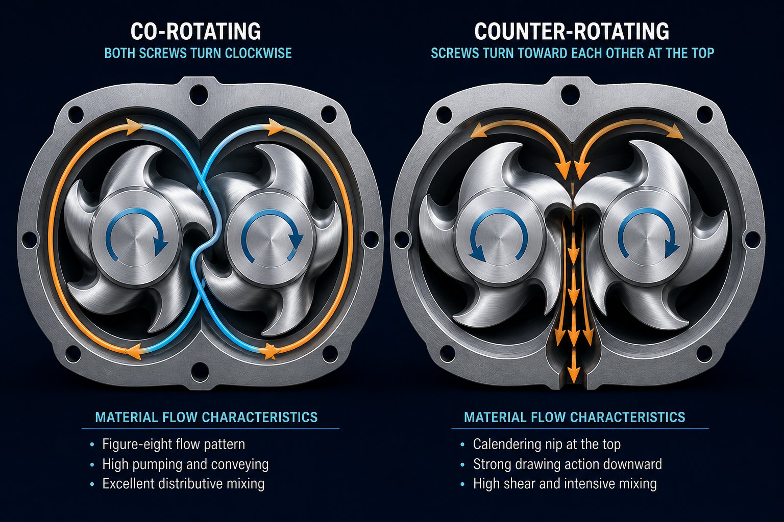
In a co-rotating twin screw extruder, both screws turn in the same direction — both clockwise or both counterclockwise. The fully intermeshing geometry means the flight of one screw fits tightly into the channel of the other. Imagine the material's path from above: it follows a figure-eight (or infinity-shaped) flow pattern, transferring from one screw to the other at every intermeshing zone. Each handoff forces the material to change direction, stretch, fold, and recombine — exactly the kind of complex deformation history that produces thorough mixing.
This geometry also creates a powerful self-wiping action. As each flight sweeps through its partner's channel, it scrapes adhered material off the screw surfaces, leaving virtually no dead zones where polymer can stagnate and degrade. The result is a narrow residence time distribution — critical for reactive extrusion and thermally sensitive materials where every second of exposure matters.
You'll notice why co-rotating designs dominate compounding applications. The intense shear fields that develop both between the screws and between each screw and the barrel wall deliver superior dispersive mixing — breaking apart filler agglomerates, splitting droplets in polymer blends — while the figure-eight flow path simultaneously provides excellent distributive mixing, spreading those broken-down particles uniformly through the melt. Add the freedom to arrange conveying elements, kneading blocks, and special mixing elements in any sequence along the shaft, and you have a machine that can be tuned for everything from nanocomposites to polymer alloys.
Counter-Rotating and Conical Configurations
Flip the rotation of one screw, and the physics change dramatically. In a counter-rotating twin screw extruder, the screws turn toward each other at the top of the intermeshing region. Material gets drawn into the gap between the screws, compressed, and pushed forward — a mechanism that closely resembles the nip of a calender roll. This calendering effect traps material between flights and conveys it with strong positive displacement, meaning transport depends primarily on screw rotation rather than drag forces.
The shear intensity drops significantly compared to the co-rotating type. That sounds like a disadvantage until you consider materials like rigid PVC, which has a low thermal decomposition temperature and poor melt flow. High shear would generate excessive frictional heat and degrade the polymer. The counter-rotating configuration allows extrusion at low temperatures with high fill levels and relatively low RPM, preserving material integrity while still providing the compressive and elongational deformation needed to disperse additives gently.
This is where the distinction between a parallel twin screw extruder and a conical twin screw extruder becomes important. Parallel designs maintain a uniform screw diameter from feed to discharge — the standard layout for co-rotating compounding machines. Conical designs, by contrast, feature screws that taper from a large diameter at the feed end to a smaller diameter at the discharge end. The taper creates a natural compression zone and allows the gearbox to transmit higher torque because the wider feed-end shafts provide more structural strength. Conical twin screw extruders are almost always counter-rotating and are heavily used in PVC pipe, sheet, and profile extrusion lines.
Intermeshing vs Non-Intermeshing Flow Paths
Beyond rotation direction, the degree of intermeshing adds another layer. Fully intermeshing designs — where the distance between screw axes is shorter than the sum of their outer radii — provide the tightest screw-to-screw interaction, maximizing mixing efficiency and self-wiping. Partially intermeshing designs introduce a small clearance between flights, reducing shear intensity while still maintaining some screw interaction. Non-intermeshing configurations space the screws far enough apart that they operate almost independently, relying on friction-based conveying and offering a much gentler processing environment.
In an animation, you would see the difference immediately. Fully intermeshing co-rotating screws show material being actively wiped from one screw to the other in a continuous figure-eight stream. Counter-rotating intermeshing screws show material being pinched and calendered in the nip zone. Non-intermeshing screws show two largely separate helical flows with limited cross-screw exchange. Each flow path suits different materials and goals.
The table below captures these differences at a glance for the two primary configurations — co-rotating and counter-rotating twin screw extruder designs:
| Feature | Co-Rotating Twin Screw Extruder | Counter-Rotating Twin Screw Extruder |
|---|---|---|
| Rotation Direction | Both screws turn the same direction | Screws turn in opposite directions |
| Intermeshing Behavior | Fully intermeshing; figure-eight material transfer | Intermeshing with calendering nip effect |
| Self-Wiping Capability | Excellent — flights continuously wipe partner screw | Limited — less aggressive wiping action |
| Shear Intensity | High — strong shear between screws and barrel | Lower — compressive and elongational deformation |
| Mixing Quality | Superior dispersive and distributive mixing | Moderate — gentle dispersion via calendering |
| Typical Applications | Compounding, reactive extrusion, masterbatch, nanocomposites | PVC pipes, profiles, sheets; heat-sensitive materials |
| Common Geometry | Parallel (uniform diameter) | Parallel or conical (tapered) |
Understanding the interplay between co-rotating and counter-rotating configurations is essential, but it only tells you how the screws move. The real question — and the part that brings a twin screw extruder animation to life — is what happens to the material itself as it travels through each processing zone, from the moment it enters the feed throat as a solid pellet to the instant it exits the die as a shaped melt.
Zone-by-Zone Written Walkthrough of the Twin Screw Extrusion Process
Here is where the written animation truly begins. Forget the exploded views and static geometry comparisons — this section puts you inside the barrel, traveling alongside the material as it transforms from dry pellets into a pressurized, homogenized melt. Think of it as a time-lapse shot, slowed down frame by frame, revealing every critical event along the way.
A typical extruder twin screw configuration divides the barrel into five distinct processing zones. Each zone has a specific job, a specific screw element arrangement, and a specific set of physical conditions acting on the material. They flow into one another without hard boundaries, but for clarity, here they are in sequence:
- Solid Conveying Zone — Raw material is captured, gripped, and transported forward as a loose solid bed.
- Melting / Plastication Zone — Heat and shear combine to transform solid particles into a continuous viscous melt.
- Melt Mixing Zone — Fully molten polymer is split, reoriented, and recombined to achieve thorough homogenization.
- Metering / Pumping Zone — Tight-pitch conveying elements stabilize flow and build consistent pressure toward the die.
- Die Zone — Pressurized melt is forced through a shaped orifice, acquiring its final cross-sectional geometry.
Each zone represents a different frame in the animation. Let's step through them.
Solid Conveying and Feed Zone Dynamics
Imagine peering down through the hopper. Pellets cascade by gravity into the feed throat — a cooled barrel opening designed to prevent premature softening. As they drop into the partially filled screw channels below, the rotating flights immediately grip them. This is drag-flow conveying: the friction between the moving screw surfaces and the stationary barrel wall creates a net forward push that drives the material downstream.
Here is the detail that separates twin screw extruders from their single-screw counterparts. At the intermeshing region — where the flights of one screw reach into the channel of the other — pellets cannot simply ride along passively on a single screw. The interlocking geometry forces material to transfer between screws, disrupting any tendency to rotate in place without advancing. The result is a more positive and consistent forward conveyance, even with irregular feedstocks like powders, flakes, or low-bulk-density recycled materials.
In this zone, the screw elements feature deep channels and a large pitch — meaning wide spacing between flights. The design maximizes free volume, giving the material plenty of room to enter without being compressed prematurely. Barrel temperatures here are kept relatively low, sometimes only slightly above ambient, because the goal is purely transport. Heating comes later. If you watched this zone in an animation, you would see loosely packed solids tumbling in partially filled channels, with visible air gaps between pellets — a telltale sign of the starve-fed operation that is standard for co-rotating twin screw systems.
Melting, Mixing, and Plastication in Motion
The conveying elements carry the solid bed forward until it encounters the first kneading blocks — and this is where the animation becomes dramatic. In the melting zone, barrel heaters ramp temperatures upward, typically into the 150 to 280 degree Celsius range depending on the polymer. Simultaneously, the kneading blocks begin to work the material mechanically.
Picture a series of offset elliptical lobes — each disc rotated at a stagger angle from the one before it. As the kneading block rotates, it stretches, squeezes, and folds the softening pellets between each lobe and between the lobe tips and the barrel wall. This narrow gap at the screw tip is where shear rate peaks, and the polymer passing through it absorbs enormous frictional energy. The temperature of the material itself rises — not just from the barrel heaters, but from the mechanical work being imparted by the screws. Industry experts note that twin screw extruders are fundamentally powerful energy-input devices, with the motor contributing the dominant share of the energy that melts the polymer.
Visualize the melt forming: a thin film of molten polymer appears first on the barrel wall, where conducted heat is highest and shear stress is greatest. This melt pool grows inward toward the screw root as more energy transfers into the solid bed. Unmelted particles get dragged through the growing melt film, further accelerating the transition. By the end of the melting section, the kneading blocks — often ending with 90-degree neutral or reverse-stagger elements — create a restriction that acts as a melt dam. This restriction ensures no solid particles slip through unmelted, because the local residence time in this zone must be sufficient to complete plastication.
Right after the melting zone, the material transitions into the melt mixing zone. Here the polymer is fully liquid — a viscous, high-temperature fluid flowing through dedicated mixing elements. In a co-rotating system, the figure-eight flow path created by the intermeshing screws does the heavy lifting. The melt stream splits at the intermeshing region, wraps around each screw, and recombines on the other side. Every split-and-recombine cycle reorients the flow, stretching it in new directions. This is distributive mixing — spreading additives, colorants, and fillers evenly throughout the melt volume.
Dispersive mixing happens simultaneously. When the melt passes over kneading block tips or through narrow clearances between screws, the high shear stress physically breaks apart agglomerated filler particles and ruptures liquid droplets in polymer blends. You would see, if the animation could zoom in far enough, individual carbon black clusters or glass fiber bundles being torn apart and distributed into the surrounding matrix. The combination of both mixing modes — dispersive to break things down, distributive to spread things out — is what makes the twin screw extrusion process uniquely effective for compounding.
Metering, Pressure Build, and Die Exit
After mixing, the melt enters a calmer region. The metering zone uses conveying elements with a tighter pitch — meaning the flights are spaced more closely together. This geometry reduces the channel volume per turn, which increases the degree of fill and steadily builds back-pressure as the melt approaches the die. Imagine the screw channels here looking completely full, with no visible air gaps — a stark contrast to the partially filled channels of the feed zone.
The purpose is stabilization. Pressure fluctuations that developed during the turbulent melting and mixing stages are dampened here as the melt flow becomes consistent and predictable. Temperature uniformity also improves. By the time the polymer reaches the end of the metering section, it flows at a steady volumetric rate and a uniform temperature — both essential for producing dimensionally consistent product.
At the terminal end of the barrel sits the die. This is the final frame of the animation. All the accumulated pressure — built gradually through the metering zone and backed by the continuous forward push of the screws — forces the melt through the die orifice. The cross-sectional shape of that orifice defines the product: a circular hole for strand pelletizing, a flat slot for sheet or film, an annular gap for pipe, or a complex profile for window frames and decking. The melt exits the die, meets ambient air or a cooling bath, and solidifies into its finished geometry.
To put the entire journey in perspective, follow a single polymer pellet through the complete screw extrusion sequence. It enters the feed throat at roughly 25 degrees Celsius and atmospheric pressure — a rigid, opaque granule with no deformation. Within seconds, it is gripped by screw flights, pushed into the melting zone, and heated past its softening point. Kneading blocks stretch and fold it as frictional heat and barrel conduction raise its temperature through 150, 200, and beyond 250 degrees Celsius depending on the polymer grade. It transitions from a solid into a viscous fluid. Mixing elements then split and recombine the melt stream it now belongs to, blending it uniformly with additives. Pressure builds from atmospheric to anywhere between 20 and 200 bar as it approaches the die. It exits as a tiny fraction of a continuous, shaped melt stream — chemically the same molecule it always was, but physically transformed from a hard granule into a flowing liquid, and geometrically reformed into whatever shape the die dictates.
That transformation — solid to melt, atmospheric to pressurized, chaotic to homogeneous — is the entire story a twin screw extruder animation compresses into a few seconds of looping video. Seeing it narrated zone by zone, though, reveals why each section exists and what goes wrong if even one zone underperforms. The deeper question becomes: what specific screw element geometries create these zones, and how does changing a single kneading block stagger angle or pitch dimension ripple through the entire processing profile?
Screw Element Design and Kneading Block Mechanics
The zone-by-zone journey described above depends entirely on which screw elements occupy each section of the shaft. Swap one kneading block for a conveying element, change a stagger angle from 30 degrees to 90 degrees, or shorten the pitch on a helical flight — and the entire processing profile shifts. This is the level of detail that makes a twin screw extruder animation so valuable: you can actually watch how different element geometries redirect, squeeze, and fold material in real time. Here, we break down the three primary families of screw elements so you can understand exactly what each one does — and why it looks the way it does when spinning inside the barrel.
Conveying Elements and Pitch Geometry
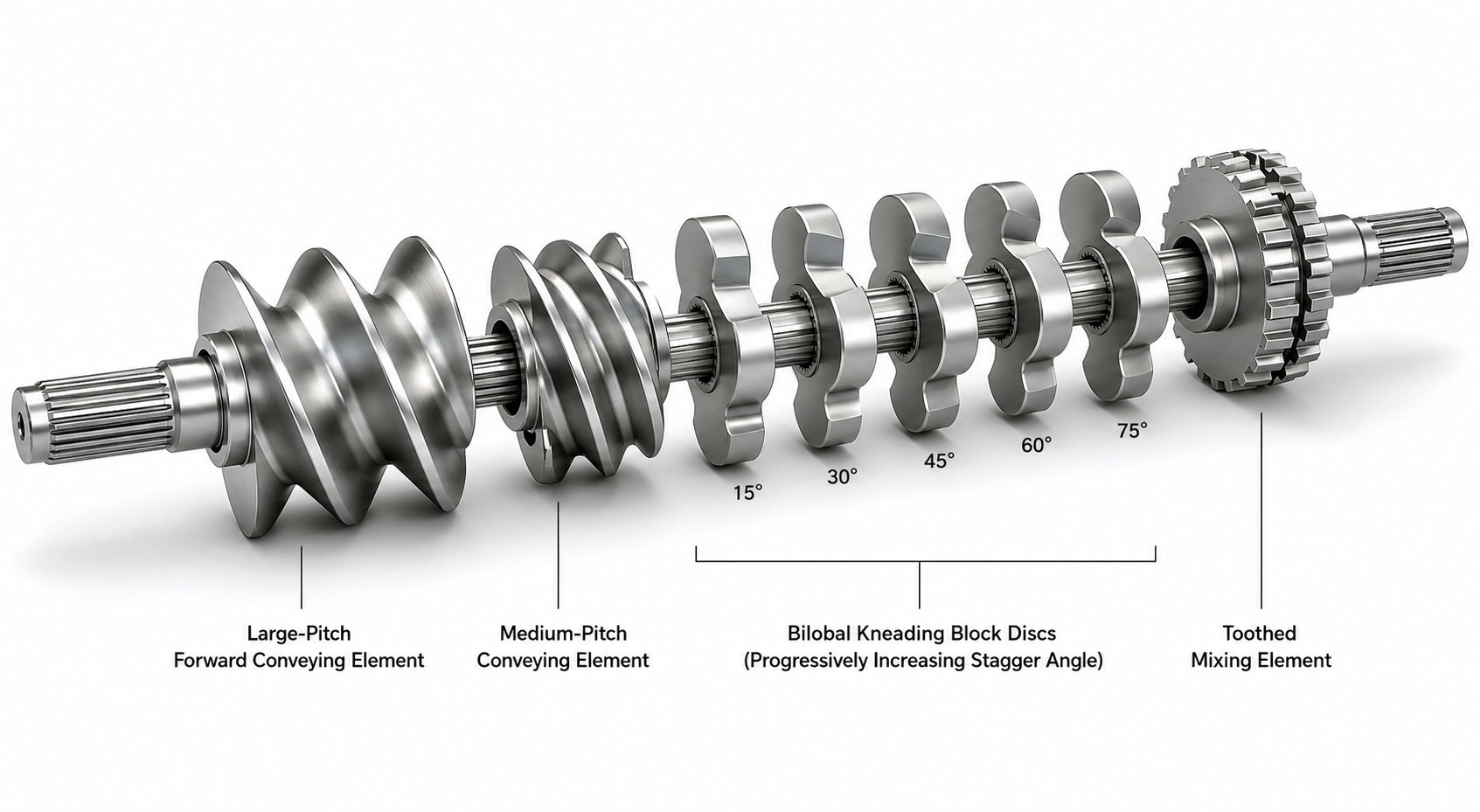
Conveying elements are the workhorses of any compounding extruder configuration. They look exactly like what you would expect from a screw — continuous helical flights wrapping around a cylindrical core. Their job is straightforward: transport material from one location to the next along the barrel. But simplicity in function hides real sophistication in geometry, because the pitch of those flights controls everything about how fast material moves and how much pressure builds up behind it.
Pitch is the axial distance covered by one full revolution of the flight. A large pitch — roughly 1.5 to 2 times the screw diameter — creates wide, open channels. Material moves forward quickly, fill levels stay low, and almost no pressure builds up. These wide-pitch elements are ideal for the feed zone and around vent ports where you want maximum open volume and fast throughput. A medium pitch, around 1 times the diameter, offers balanced conveying speed and moderate fill. A small pitch — 0.25 to 0.75 times the diameter — packs the material tightly, slows its forward movement, and generates significant pressure buildup. You will find these tight-pitch elements in the metering zone just upstream of the die, where consistent pressurization is the goal.
Imagine watching this in an animation. In the feed section, wide-pitch elements show loosely packed material rolling through open channels with visible air gaps. Toward the die, tight-pitch elements show fully packed channels with no gaps — the visual transition from starve-fed to pressure-driven flow happens right before your eyes.
There is another critical variant: reverse conveying elements. These have the same helical flight geometry but with an opposite hand — if the forward elements are right-handed, the reverse elements are left-handed. Instead of pushing material toward the die, they push it backward. Sounds counterproductive? It is actually essential. By placing a short reverse element upstream of a vent port, you create a back-pressure seal — a zone of high fill and elevated pressure that acts as a dam. Molten polymer cannot flow backward through the vent because the melt seal holds it in place, while volatiles escape freely through the open port above. Without this trick, devolatilization would be impossible.
The number of flights — often called the number of threads or lobes — adds another dimension. Double-flighted (bilobal) conveying elements are the standard for co-rotating twinscrew systems, offering a balance between conveying capacity, shear input, and suction efficiency. Single-flighted elements have wider flights that minimize leakage flow over the flight tip, making them excellent for vacuum zones where maximum sealing matters. Triple-flighted elements feature shallow channels and generate the highest shear rates, which makes them useful for accelerating melting or intensifying mixing in specific zones — though at the cost of reduced free volume.
Kneading Block Stagger Angles and Mixing Intensity
If conveying elements are the workhorses, kneading blocks are the artisans. These are the elements that transform a simple conveying machine into a twin screw compounding extruder capable of dispersing fillers, blending polymers, and driving chemical reactions. Their geometry is fundamentally different from conveying elements — instead of a continuous helical flight, a kneading block consists of a series of elliptical or lenticular discs stacked along the shaft, each one rotated at a fixed angle relative to the disc before it. That angle — the stagger angle — is the single most important variable controlling mixing intensity.
In co-rotating systems, the standard kneading disc is bilobal — two lobes per cross-section, creating the familiar figure-eight profile that intermeshes with its partner on the adjacent screw. As the block rotates, material gets trapped between the lobe tips and the barrel wall, squeezed through the narrow gap, then released and reoriented by the next offset disc. Every disc transition represents a fold-and-stretch event that splits and recombines the melt stream.
Here is where stagger angle becomes decisive:
- 30-degree forward kneading blocks gently advance material while providing minimal mixing. The small angular offset between discs means the flow channel from one disc to the next remains nearly continuous, so material passes through quickly. These blocks suit applications where you need a light touch — gentle blending without aggressive shear.
- 45-degree forward kneading blocks increase both mixing intensity and residence time. The larger offset forces material to change direction more abruptly between discs, creating moderate dispersive and distributive mixing action.
- 60-degree forward kneading blocks deliver strong mixing with reduced conveying capability. Material spends noticeably longer in this section, giving the shear forces more time to break apart agglomerates and homogenize the melt.
- 90-degree (neutral) kneading blocks provide no forward conveying at all. The discs are offset at right angles, meaning each one pushes material sideways rather than forward. The result is 100 percent fill, maximum shear, and intense dispersive mixing. These are the elements you see in the most aggressive mixing zones of a compounding twin screw extruder — the point where filler clusters get torn apart and incompatible polymer phases get forced into intimate contact.
- Reverse kneading blocks actively push material backward, creating even more restriction than neutral blocks. They generate extreme residence time and intense mixing in the upstream zone, essentially forming a dam of material that must be forced through by the forward-conveying elements behind it. Use them sparingly — they are powerful but can cause overheating in thermally sensitive formulations.
In an animation, the difference is visually striking. Forward 30-degree blocks show material gliding through with a gentle ripple. As the stagger angle increases to 60 and then 90 degrees, you would see the flow becoming turbulent, material folding back on itself, and the channels filling completely as the forward momentum stalls. Reverse kneading blocks would show material actually backing up — a momentary upstream surge before the pressure from upstream conveying elements forces it through.
Disc width also matters. Wider kneading discs promote dispersive mixing because the material spends more time under shear in each lobe gap. Narrower discs favor distributive mixing, creating more fold-and-recombine cycles per unit length without as much shear intensity per cycle. A skilled process engineer selects not just the stagger angle but also the disc width and the total number of discs in each block to fine-tune the energy input for a specific material.
Special Mixing and Restriction Elements
Beyond conveying elements and kneading blocks, a third family of specialized elements rounds out the toolkit. These components serve niche but critical functions that the first two families cannot efficiently achieve on their own.
Toothed mixing elements (TME/ZME) replace the continuous lobe geometry with rows of individual teeth arranged around the circumference. As the element rotates, the teeth intermesh with those on the adjacent screw, splitting the melt into many small streams that recombine on the other side. This geometry excels at distributive mixing with very low shear input — ideal for blending heat-sensitive additives, color concentrates, or liquid additives into a polymer melt without degrading them.
Blister rings are short cylindrical elements with a very tight clearance to the barrel wall. They act as restrictive dams, creating a melt seal by forcing material through a narrow annular gap. Engineers place blister rings upstream of vent ports — similar to reverse conveying elements — to seal the melt and separate processing zones at different pressures. Their advantage is simplicity and a very compact axial footprint.
Distributive mixing elements — sometimes proprietary designs like screw mixing elements (SME) or gear mixing elements — use slotted or grooved geometries to repeatedly divide and recombine the melt stream. They offer a middle ground between the aggressive dispersive action of kneading blocks and the gentle splitting action of toothed elements.
The table below summarizes the key element families, their geometry, and their processing effects — essentially the visual legend you would reference while watching a twin screw extruder animation:
| Element Type | Geometry Description | Stagger Angle | Primary Function | Mixing Effect |
|---|---|---|---|---|
| Forward conveying (large pitch) | Continuous helical flights, wide spacing | N/A | Fast material transport, feed and vent zones | Minimal — no significant mixing |
| Forward conveying (small pitch) | Continuous helical flights, tight spacing | N/A | Pressure build, metering zone | Minimal — compression only |
| Reverse conveying | Opposite-hand helical flights | N/A | Back-pressure seal, melt dam for venting | Indirect — increases upstream fill and shear |
| 30° forward kneading block | Stacked bilobal discs, small offset | 30° | Gentle mixing with forward conveying | Low dispersive, low distributive |
| 45° forward kneading block | Stacked bilobal discs, moderate offset | 45° | Moderate mixing with reduced conveying | Moderate dispersive, moderate distributive |
| 60° forward kneading block | Stacked bilobal discs, large offset | 60° | Strong mixing with minimal conveying | High dispersive, moderate distributive |
| 90° neutral kneading block | Stacked bilobal discs, perpendicular offset | 90° | Maximum shear, no forward conveying | Maximum dispersive, moderate distributive |
| Reverse kneading block | Stacked bilobal discs, reverse offset | Varies (negative) | Backward push, extreme restriction | Very high dispersive, high distributive |
| Toothed mixing element (TME/ZME) | Rows of intermeshing teeth on cylindrical body | N/A | Low-shear blending and homogenization | Low dispersive, high distributive |
| Blister ring | Short cylinder with tight barrel clearance | N/A | Melt seal, zone separation | Negligible — restriction only |
| Distributive mixing element (SME/gear) | Slotted or grooved geometry | N/A | Stream splitting and recombination | Low dispersive, high distributive |
When you watch an animation of a running compounding twin screw extruder, these are the shapes you see spinning inside the barrel. Conveying elements produce smooth, predictable helical flow — material gliding forward in orderly ribbons. Kneading blocks shatter that order. The melt gets pinched between offset lobes, squeezed through narrow clearances, folded over itself, and pushed sideways before being picked up again by the next conveying section. Toothed elements show a gentler version of this disruption — many small streams splitting and merging like tributaries in a braided river. Each element family creates a visually distinct flow signature, and it is the deliberate sequencing of these signatures along the shaft that defines a screw configuration.
Knowing what each element does, though, is only half of the picture. The other half is understanding how the operator's choices — screw speed, feed rate, and fill level — interact with these fixed geometries to change the actual processing outcome for every kilogram of material that passes through.
How RPM and Throughput Shape the Twin-Screw Extruder Machine Process
A perfectly designed screw configuration sitting motionless inside a barrel does nothing. The moment the motor starts and pellets begin falling from the hopper, two operator-controlled variables take over: screw speed (RPM) and feed rate (throughput in kg/h). These two knobs — independent of each other in a twin screw system — determine how much material fills the screw channels, how long it stays inside the machine, and how much mechanical energy every kilogram absorbs. Change one without adjusting the other, and the entire processing profile shifts. This interplay is arguably the most important dynamic a twin screw extruder animation can reveal, because it plays out continuously in real time and is invisible from the outside of the machine.
Screw Speed and Specific Energy Input
Imagine holding the feed rate constant at, say, 50 kg/h while gradually increasing the screw speed from 200 RPM to 600 RPM. What happens inside the barrel? The screws spin faster, sweeping material through the channels more quickly. Because the same amount of material enters per minute but the screws are moving it forward faster, each screw channel becomes less full — the fill level drops. Material spends less time inside the extruder, so the residence time shortens.
At the same time, something else is changing dramatically. Faster screw rotation means the shear rate between the screw tips and barrel wall increases proportionally. Higher shear rate translates directly into more frictional heating — more mechanical energy driven into every gram of polymer. Experimental data from Technovel confirms that screw speed is the single operational variable with the strongest effect on melt temperature in twin screw extrusion. In their tests on a laboratory twin screw extruder, raising the screw speed at constant throughput caused melt temperature to climb while discharge pressure actually dropped — the viscosity decrease from the hotter melt reduced the pressure loss through the die.
This is the concept of specific energy — the mechanical energy delivered per unit mass of material, typically expressed in kWh/kg. It is calculated from the motor's effective power output divided by the throughput. Increase RPM without increasing feed rate, and specific energy rises, because you are putting more mechanical work into the same amount of material. The result can be excellent dispersion and mixing — or, if pushed too far, thermal degradation. The polymer's molecular chains begin to break down, discoloration appears, and mechanical properties suffer. In co-rotating, fully intermeshing systems especially, the wiping action between the screws transfers mechanical energy to the material with high efficiency, which makes this temperature sensitivity even more pronounced.
If you could watch this in an animation, you would see the screw channels becoming visibly emptier as RPM climbs. Material occupies only the lower portion of each channel, and the intermeshing zone between the two screws becomes clearly exposed — you can see the flight tips of each screw sweeping through the partner's channel with minimal material in between. The polymer moves through faster, gets hit harder, and exits hotter.
Starve-Fed Operation and Fill Level Dynamics
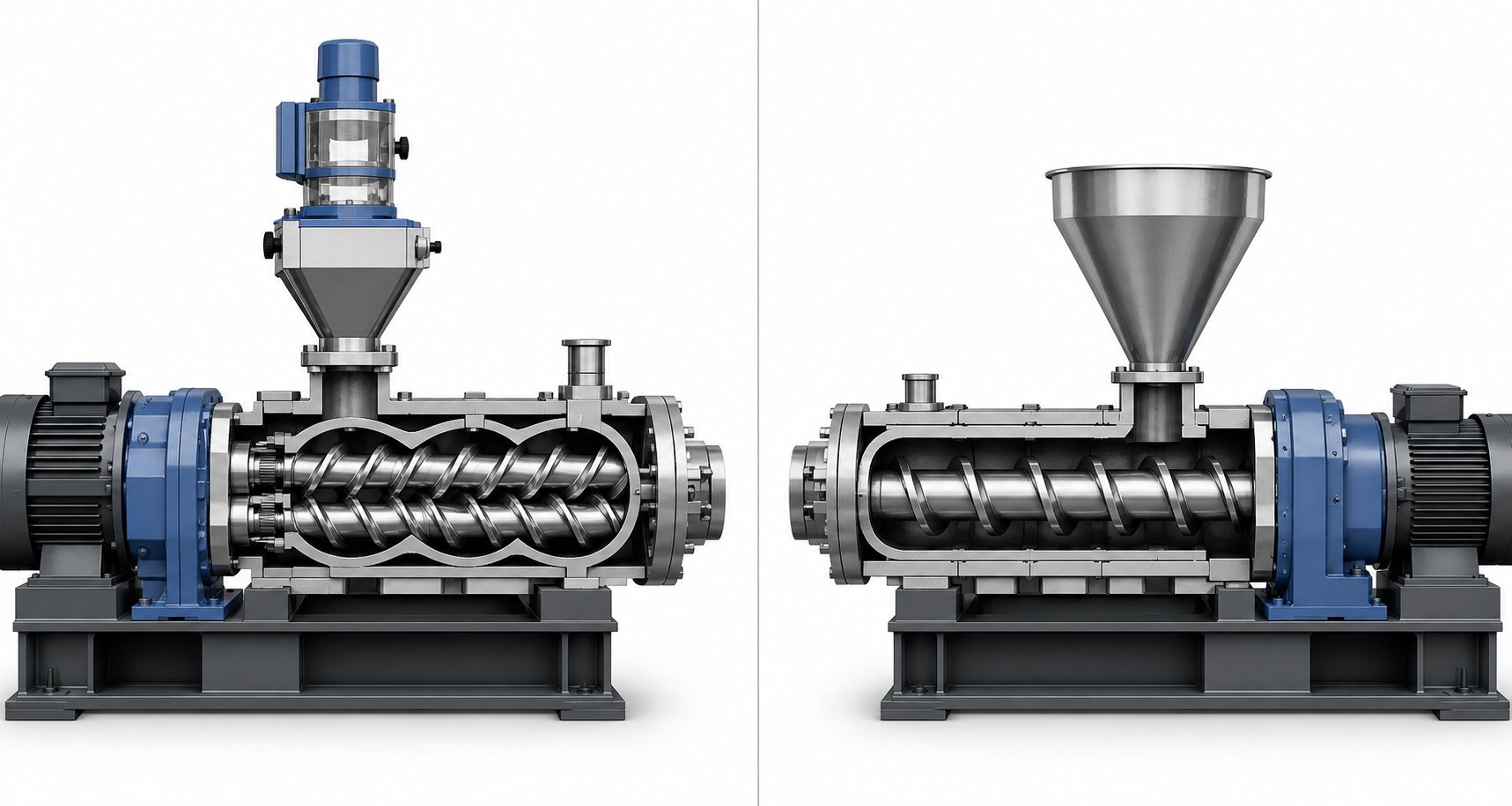
Here is a fact that surprises many people encountering twin screw extrusion for the first time: co-rotating twin screw extruders are almost universally starve-fed, not flood-fed. In a single screw extruder, the hopper sits directly over the feed zone and gravity-floods material into the screw channel as fast as the screw can take it — feed rate and screw speed are coupled. In a twin-screw extruder machine, a separate metering device — usually a gravimetric (loss-in-weight) feeder — sits above the feed throat and delivers material at a precisely controlled rate that is independent of screw speed.
Why does this matter so much? Because it gives the operator two independent levers rather than one. Screw speed controls the shear rate and the energy input. Feed rate controls how much material occupies the screw channels — the fill level. Adjusting either one independently changes the process outcome without touching the other. This decoupling is fundamental to process optimization on any twin screw system, from a small benchtop twin screw extruder in a research lab to a production-scale machine running 2,000 kg/h.
The ratio between these two variables is captured by a parameter called Q/N — throughput (Q) divided by screw speed (N). Research using split-barrel visualization has shown that at a given Q/N, the fill state in the partially filled conveying sections remains essentially constant, regardless of whether you achieve that ratio at low Q and low N or at high Q and high N. Raise Q/N by increasing the feed rate at constant screw speed, and the fill level rises — more material sits in the channels at any given moment. Lower Q/N by increasing screw speed at constant feed rate, and the channels empty out.
There is an important subtlety, though. Even when two conditions share the same Q/N, the residence time and shear history can be vastly different. Doubling both the feed rate and the screw speed keeps Q/N constant, but the material now travels through the barrel roughly twice as fast and experiences twice the shear rate. So Q/N tells you about fill level, not about the complete processing experience. That requires looking at Q/N alongside absolute RPM and the screw configuration together.
In an animation at high fill (high Q/N), the screw channels appear packed — material fills the flights from root to tip, and the flow looks pressure-driven, with the polymer being pushed forward in a solid mass. At low fill (low Q/N), you would see material occupying only the bottom arc of each channel, riding loosely in partially filled flights, with visible voids and the intermeshing region clearly exposed. The transition between these two states is smooth and continuous, responding in real time to any change the operator makes to the feeder setpoint or the RPM dial.
Balancing Throughput, Mixing, and Residence Time
Every process engineer faces the same optimization puzzle: maximize throughput without sacrificing product quality. The challenge is that throughput, mixing quality, and residence time pull against each other.
Increasing feed rate at constant RPM raises throughput — great for productivity — but it also increases the fill level. Higher fill means more shear stress acts on the material, which can improve dispersion up to a point. Push the feed rate too high, however, and the screw channels become overfilled. Pressure spikes. Viscous heating climbs beyond what barrel cooling can remove. The motor draws more current, and in extreme cases, the drive hits its torque limit. Material also spends more time in the barrel under these high-fill conditions, which extends the thermal history and raises the risk of degradation for heat-sensitive polymers.
Increasing RPM at constant feed rate lowers the fill level and shortens residence time. For materials that need only moderate mixing, this is a fast way to boost throughput because you can then increase the feed rate proportionally to restore the original fill level — effectively scaling production while holding process conditions similar. But if the RPM goes too high relative to the feed rate, the material may not spend enough time in the kneading zones to achieve complete melting, homogenization, or reaction. Undertreated material exits the die with unmelted gels, poorly dispersed fillers, or incomplete chemical conversion.
Inconsistent feeding creates its own set of problems. If the gravimetric feeder experiences bridging, ratholing, or pulsating flow, the fill level inside the barrel fluctuates from moment to moment. The result is surging — periodic waves of high and low pressure arriving at the die. Product dimensions oscillate, surface quality degrades, and downstream equipment struggles to maintain stable operation. This is precisely why feeder selection and maintenance receive just as much attention as screw design in professional compounding operations.
The table below summarizes how each variable acts on the process and what combined strategies operators use to find the sweet spot:
| Variable Change | Fill Level | Residence Time | Specific Energy (SME) | Melt Temperature | Mixing Quality | Risk if Excessive |
|---|---|---|---|---|---|---|
| Increase RPM (constant feed rate) | Decreases | Shorter | Increases | Rises (shear heating) | May improve dispersion but shorter exposure | Thermal degradation, insufficient residence for reactions |
| Increase feed rate (constant RPM) | Increases | Longer | Decreases per kg | Rises (viscous heating from higher fill) | May improve at moderate fill; declines if overfilled | Motor overload, excessive pressure, poor temperature control |
| Increase both RPM and feed rate (constant Q/N) | Approximately constant | Shorter (higher absolute speed) | Depends on ratio | Rises with absolute RPM | Similar fill-based mixing, less time per pass | Scale-up melt temperature overshoot |
| Decrease RPM (constant feed rate) | Increases | Longer | Decreases | Lower shear heating | May decline if shear becomes insufficient | Incomplete melting, poor dispersion, torque limit |
| Decrease feed rate (constant RPM) | Decreases | Shorter | Increases per kg | Rises (more energy per unit mass) | May improve if previously overfilled | Overheating at very low fill, reduced throughput |
The key insight from this table is that melt temperature and melt pressure are never determined by a single variable in isolation. They emerge from the interaction between screw speed and throughput — from the fill state and energy input state acting together. A process that works perfectly at 300 RPM and 100 kg/h on a benchtop twin screw extruder may produce entirely different results at 300 RPM and 100 kg/h on a production machine, because the larger screw diameter increases the peripheral speed and the shear rate at the same nominal RPM. This is one of the most common pitfalls during scale-up: conditions that ran beautifully on a small laboratory twin screw extruder generate unexpectedly high melt temperatures when transferred to a larger platform without adjusting the RPM-to-throughput balance.
Understanding these operational dynamics transforms how you read a twin screw extruder animation. Instead of simply watching material flow forward, you begin to see the fill level, estimate the residence time, and predict the shear intensity just from how full the screw channels appear and how fast the elements are spinning. It adds a quantitative dimension to the visual — which is exactly the kind of process intuition that separates a machine operator from a process engineer. The next question, naturally, is how all of this compares to the simpler single-screw alternative — and where the twin screw design's independent control of RPM and feed rate gives it an advantage that a single screw physically cannot match.
Twin Screw vs Single Screw Extruder Comparison
The independent control of RPM and feed rate discussed in the previous section is not just an operational convenience — it is a mechanical impossibility on a single screw extruder. That distinction alone hints at a deeper structural divide between the two machine types. Many industry guides mention this comparison in passing, but rarely explain why these differences exist at a mechanical level. Let's fix that.
Mixing, Conveying, and Self-Cleaning Compared
A single screw extruder uses one rotating screw inside a smooth cylindrical barrel. Material moves forward through drag flow — friction between the polymer, the rotating screw, and the stationary barrel wall generates a net forward push. There is no second screw to interact with, no intermeshing zone, and no figure-eight flow path. This means the five high-shear regions identified in twin-screw extruders — screw channel, overflight, lobal pool, apex, and intermesh — collapse down to essentially two in a single screw system: the screw channel and the overflight gap. The intermesh zone, which research from Leistritz identifies as a high-intensity mixing region independent of fill level, simply does not exist on a single screw machine.
That missing intermesh explains nearly every performance gap. Without screw-to-screw wiping, material can stagnate in dead zones along the channel, leading to degradation. Without the apex compression-decompression effect, extensional mixing is minimal. Without the calender or figure-eight transfer between screws, the only way a single screw can mix is through shear in the flight clearance and whatever limited reorientation occurs as the melt spirals forward. The result is adequate distributive mixing for simple blending tasks, but poor dispersive mixing when you need to break apart agglomerates, rupture droplets in immiscible blends, or drive chemical reactions to completion.
Self-cleaning ability follows the same logic. In a co-rotating double screw extruder, each flight tip sweeps through the adjacent screw's channel with minimal clearance, scraping the surfaces clean and pushing material forward in a first-in, first-out sequence. A single screw has no such mechanism. Residual material clings to the screw root and barrel wall until it is either displaced by new material or manually purged during a changeover. For operations that run multiple products on the same line, this means longer transition times, more waste, and higher contamination risk.
Feed flexibility is another consequence of the mechanical design. Single screw extruders are flood-fed — material fills the feed zone by gravity, and the screw's conveying capacity sets the throughput rate. This works well for uniform pellets but struggles with powders, fibers, or low-bulk-density recyclate that bridge in the hopper or slip in the feed zone. Twin-screw extruders, with their starve-fed operation and independent gravimetric feeders, accept a far wider range of feedstock forms because the intermeshing action positively grips and conveys even difficult materials without relying solely on frictional drag.
The following table captures these differences across every major performance dimension:
| Performance Dimension | Twin Screw Extruder | Single Screw Extruder | Why the Difference Exists |
|---|---|---|---|
| Mixing Efficiency | Excellent dispersive and distributive mixing | Adequate distributive; limited dispersive | Intermeshing zone creates high-shear transfer and extensional flow absent in single screw |
| Feed Flexibility | Handles pellets, powders, fibers, liquids; starve-fed | Primarily pellets; flood-fed | Positive intermeshing conveying grips irregular feedstocks; independent feeder decouples rate from RPM |
| Residence Time Distribution | Narrow and controllable | Broad and less predictable | Self-wiping action enforces first-in, first-out flow; no dead zones for material to stagnate |
| Self-Cleaning Ability | Co-rotating screws are self-wiping | No self-cleaning; requires manual purging | Each screw flight wipes the adjacent screw's channel — a geometry impossible with a single screw |
| Throughput Control | Independent of screw speed (starve-fed) | Coupled to screw speed (flood-fed) | Separate gravimetric feeder sets rate; screws only process what is metered in |
| Venting Capability | Multi-stage vacuum venting at multiple barrel positions | Limited; typically one atmospheric vent | Starve-fed operation creates zero-pressure zones under vents; reverse elements seal the melt upstream |
| Capital Cost | Higher initial investment | Lower initial investment | Complex gearbox synchronizing two shafts, modular barrel, segmented screws increase manufacturing cost |
| Typical Applications | Compounding, reactive extrusion, devolatilization, masterbatch | Simple melting and forming: film, sheet, pipe, profiles | Mixing-intensive tasks require the interscrew interactions only twin-screw extruders provide |
When to Choose Twin Screw Over Single Screw
The decision is rarely about which machine is "better" in an absolute sense. It is about matching the machine's mechanical capabilities to the task. If your process involves melting a single polymer and pushing it through a die — producing drinking straws, packaging film, or simple tubing — a single screw extruder delivers what you need at lower capital cost and with simpler operation. Industry data supports this: roughly ten times as many single screw extruders are installed annually compared to twin screw units, precisely because high-pressure pumping and simple forming dominate the extrusion landscape by volume.
Twin-screw extruders earn their premium the moment the process demands more than melting and pumping. Compounding glass-fiber-reinforced nylon? You need dispersive mixing to break fiber bundles and distributive mixing to spread them uniformly — only intermeshing screw extruders deliver both simultaneously. Removing residual solvent from a polymer solution? Multi-stage vacuum venting with melt seals is a twin screw specialty. Running reactive extrusion where monomers must polymerize inside the barrel? The narrow residence time distribution ensures consistent conversion. Processing post-consumer recyclate contaminated with moisture, paper labels, and mixed polymer fractions? The combination of starve feeding, aggressive venting, and self-wiping makes the double screw extruder the practical choice.
The underlying principle is straightforward: every advantage the twin screw holds — superior mixing, self-cleaning, independent throughput control, multi-stage venting — traces back to a single mechanical fact. Two intermeshing screws create positive displacement, interscrew shear zones, and a self-wiping flow geometry that one screw rotating alone inside a smooth barrel physically cannot replicate. Once you see that connection, the comparison stops being a feature checklist and becomes an obvious consequence of physics.
Knowing which machine to choose, however, is only the starting point. The real craft lies in designing the specific screw configuration — selecting the exact sequence of conveying elements, kneading blocks, and mixing elements along the shaft — to match a particular application, whether that is high-filler compounding, reactive processing, devolatilization, or plastics recycling.
Screw Configuration Design for Different Applications
Every application discussed so far — compounding, blending, reactive processing, recycling — uses the same machine platform. The same motor, gearbox, and modular barrel segments. What changes is the specific sequence of elements arranged on the twin screw shafts. Swap a 30-degree kneading block for a 90-degree neutral block, add a reverse conveying element before a vent port, or extend a mixing section by four additional disc widths, and you have fundamentally altered the processing profile. This is what makes twin screw extruder animation so educational: you can watch identical hardware produce completely different outcomes just by rearranging the elements on the shaft.
Think of the screw configuration as a recipe — not for the product, but for the process itself. Each element performs a specific task at a specific location along the barrel. The art lies in sequencing those tasks so that the material encounters exactly the right combination of conveying, melting, mixing, venting, and pressurization at precisely the right moment in its journey. Understanding this sequencing is what transforms a plastic twin screw extruder operator from someone who follows preset parameters into an engineer who designs processes from scratch.
Below are four representative configurations, each tailored to a distinct application. Notice how the same families of elements — conveying flights, kneading blocks, reverse elements, and mixing discs — appear in every configuration, but in different orders, lengths, and intensities.
Screw Configurations for Compounding and Reactive Processing
Polymer compounding with mineral fillers, glass fibers, or carbon black is the most common application for co-rotating twin screw extruder plastic processing lines. The challenge is twofold: melt the base resin thoroughly, then disperse and distribute the filler uniformly without degrading either component. Reactive extrusion adds another layer of complexity — the screws must not only mix but also provide enough residence time for a chemical reaction to proceed to completion inside the barrel.
Here is how the element sequences typically differ:
- Polymer compounding with fillers: Large-pitch forward conveying elements in the feed zone accept resin pellets from the main hopper. A first kneading section — usually 45-degree and 60-degree forward kneading blocks followed by a short 90-degree neutral block — melts the polymer aggressively. After melting, medium-pitch conveying elements transport the melt to a side-stuffer port, where a smaller twin screw feeder forces filler (calcium carbonate, talc, glass fiber) into the already molten stream. Immediately downstream, a second intensive kneading section with wide 60-degree and 90-degree blocks disperses the filler agglomerates into primary particles. Distributive mixing elements — toothed (ZME) or gear-type — follow to spread those particles evenly. A short reverse conveying element upstream of a vacuum vent creates a melt seal for devolatilization. Finally, tight-pitch conveying elements build pressure for die discharge. The key design principle: separate melting from filler incorporation so the abrasive filler never contacts unmelted pellets, reducing screw and barrel wear.
- Reactive extrusion (grafting, polymerization, crosslinking): The feed zone and initial melting section mirror a standard compounding layout. The critical difference appears in the reaction zone — an extended section of 90-degree neutral kneading blocks and narrow-pitch conveying elements designed to maximize residence time. Because neutral blocks provide zero forward conveying, material accumulates and fills completely, giving reactants the dwell time needed for chemical conversion. Reverse kneading blocks or reverse conveying elements bracket the reaction zone on both ends, creating sealed high-pressure regions that prevent unreacted monomer or volatile byproducts from escaping prematurely. Liquid injection ports within the reaction zone allow precise metering of peroxides, coupling agents, or monomers directly into the melt. Downstream, a vacuum vent strips residual volatiles, and standard metering elements pressurize the melt for pelletizing. The design philosophy here is containment and control — maintaining the material at reaction temperature under pressure for a predictable, repeatable duration.
In both configurations, the twin screw extruder manufacturers who build these machines provide standardized element catalogs with dozens of pitch sizes, kneading block widths, and stagger angles. Engineers select from that catalog the way a composer selects notes — the same twelve tones produce an infinite variety of music depending on the sequence.
Devolatilization, Pelletizing, and Recycling Configurations
Not every twin screw application is about mixing things in. Some are about getting things out — removing moisture, residual solvents, trapped air, or volatile contaminants from the polymer melt. Others focus on converting waste streams back into usable pellets. Both demand screw configurations built around venting efficiency rather than mixing intensity.
- Devolatilization (solvent or monomer stripping): After a standard melting section, the screw transitions into a series of devolatilization stages. Each stage follows a repeating pattern: a reverse conveying element or blister ring creates a fully filled melt seal, immediately followed by a large-pitch forward conveying element positioned beneath an open barrel vent connected to a vacuum pump. The large pitch ensures the screw channels are only partially filled in the vent zone, maximizing the exposed melt surface area for volatile escape. As industry devolatilization experts note, a practical rule of thumb is that each vacuum vent stage can reduce volatile concentration by roughly an order of magnitude. A triple-vented machine, for instance, can bring a 50-percent-solids polymer solution down to below 0.1 percent residuals. The downstream seal for each stage must be carefully designed — if the restriction is too tight or too close to the vent, or if throughput is too high relative to screw speed, filled screw channels can back up under the vent opening and flood the vacuum port.
- Pelletizing and recycling of post-consumer plastics: Contaminated or mixed-polymer feedstocks present unique challenges. The screw configuration for a twin screw plastic extruder in a recycling line typically begins with an extended, gently profiled melting zone — long sequences of 30-degree and 45-degree forward kneading blocks rather than the aggressive 90-degree elements used in virgin compounding. Why? Because recycled flake or regrind often contains paper labels, residual moisture, and mixed polymer fractions that can generate excessive volatile pressure if subjected to intense shear too early. After initial melting and homogenization, one or two atmospheric vents allow steam and light volatiles to escape before the material reaches a vacuum vent for deeper stripping. A melt filtration screen changer sits downstream to capture solid contaminants — metal fragments, sand, unmelted foreign polymers. The metering zone then builds pressure for strand pelletizing or underwater pelletizing. The entire configuration prioritizes gentle melting, thorough venting, and contamination removal over the high-shear dispersion that compounding demands.
What unites all four configurations is a single principle: the screw profile is not an afterthought bolted onto a generic machine. It is the process. Every element placement reflects a deliberate decision about what should happen to the material at that exact point along the barrel. Changing even one element changes everything downstream of it — fill level, pressure profile, temperature history, and mixing intensity all shift in response. This cascading interdependence is exactly what makes animated visualizations so powerful for training: you can watch the consequence of each design choice ripple through the entire system in real time.
Sourcing Precision Screw Barrels for Your Configuration
Designing the ideal screw configuration on paper is one thing. Translating it into hardware that performs reliably under production conditions is another. The tolerances involved are demanding — flight clearances of a few tenths of a millimeter between intermeshing elements, hardened surfaces that must resist abrasion from glass fibers or mineral fillers, and barrel bores machined to figure-eight profiles with consistent concentricity across every segment. When wear eventually erodes these tolerances, mixing efficiency declines, leakage flow increases, and product quality drifts — often slowly enough that operators do not notice until the problem is severe.
For technical teams running pipe, profile, sheet, pelletizing, or recycling lines, having a reliable source for replacement screw barrels and precision-engineered elements is not optional — it is infrastructure. NANHAIYA's Plastic Extruder Machine and Screw Barrel Support connects extrusion manufacturers and recycling plants with screw barrel solutions matched to their specific twin-screw extruder machine platforms. Whether you need to replace a worn kneading block section on a compounding line, upgrade barrel metallurgy for an abrasive filler application, or source complete screw sets for a new recycling installation, working with a dedicated twin-screw extruder manufacturer's support resource ensures that the hardware matches the process design — because a perfectly designed screw configuration only delivers results when every element is machined to specification and assembled with precision.
Even with the right configuration and properly manufactured components in place, real-world extrusion rarely runs without interruption. Process upsets — surging output, material backing up through vent ports, discolored product — are signals that the carefully designed balance between screw geometry, operating parameters, and material behavior has broken down somewhere. Diagnosing where, and why, requires a troubleshooting framework that connects symptoms back to the zone-by-zone dynamics covered earlier.
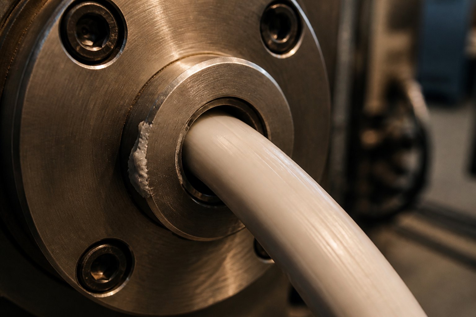
Troubleshooting Twin Screw Extrusion Problems
A perfectly configured double screw extruder machine can still produce defective output. Screw geometry, barrel temperatures, RPM, and feed rate interact in a tightly coupled system — and when any single variable drifts out of balance, the consequences show up downstream at the die. The zone-by-zone walkthrough earlier in this article gave you a clear mental model of how material should behave at each stage. Troubleshooting is what happens when reality deviates from that model. Imagine your twin screw extruder animation stuttering, freezing, or running backward in certain frames — each glitch points to a specific mechanical or thermal failure inside the barrel.
Four problems account for the majority of processing interruptions on twin screw lines. Each one maps directly back to a breakdown in the dynamics you have already learned.
Surging, Die Drool, and Output Instability
Surging is the most immediately visible problem — and the most disruptive. You notice it as a rhythmic pulsation in die pressure, strand thickness, or pellet weight. Output oscillates instead of flowing steadily. What is actually happening inside the barrel? The fill level in the screw channels is fluctuating. Perhaps the gravimetric feeder is experiencing bridging or inconsistent flow, sending waves of high and low material density into the feed throat. Or perhaps the kneading blocks in the melting zone are only partially filled during the low-feed pulses, meaning their mixing and pressure-building function drops out momentarily. The pressure wave propagates all the way to the die, causing the extrudate to swell and shrink in a repeating cycle. Extrusion troubleshooting research from Dow has shown that feed zone temperature issues — a hot screw surface or an overheated feed casing — are among the most common root causes for surging, because improper surface temperatures disrupt the balance between forwarding and retarding frictional forces that drive solids conveying.
If you were watching an animation of a surging extruder, you would see material arriving at the die in pulses — thick, thin, thick, thin — rather than in a steady, uniform stream. The screw channels upstream would show alternating bands of full and partially empty sections traveling forward like waves.
Die drool is subtler but equally damaging. A slow buildup of material accumulates on the die lip, forming a crusty ring or dangling strand that periodically breaks off and contaminates the product. The root causes trace back to the metering and die zones. Residual volatiles — moisture, trapped air, or low-molecular-weight additives — that were not fully removed at the vent ports reach the die and flash as the melt exits into atmospheric pressure. The expanding gas drags small amounts of polymer with it, depositing them on the die face. Excessive die pressure or a melt temperature that pushes the polymer past its stable processing window can also trigger melt fracture — a surface instability where the extrudate emerges with a rough, sharkskin texture and leaves residue on the die land. Correcting die drool usually means revisiting the devolatilization zone: is the vacuum level sufficient? Is the melt seal upstream of the vent holding? Is the barrel temperature profile driving off volatiles before they reach the die?
Degradation, Vent Flow, and Corrective Actions
Degradation reveals itself as discoloration — yellow or brown streaks in a product that should be white or clear — or as reduced mechanical strength in the finished part. This is a thermal and temporal problem. Either the material spent too long inside the barrel (excessive residence time from low throughput, overfilled restrictive elements, or dead zones in worn screw channels), or the melt temperature climbed too high (excessive RPM, insufficient barrel cooling, or overly aggressive kneading block configurations). In both cases, polymer chains break down. You might also see black specks — carbonized particles from material that stagnated in a dead zone, degraded over time, and eventually dislodged into the flow stream. Industry troubleshooting guides consistently identify overheating as a primary cause of material degradation, recommending regular monitoring of barrel zone temperatures and verification that cooling systems are functioning at full capacity.
Vent flow is perhaps the most alarming problem to witness. Instead of volatiles escaping cleanly through an open vent port, molten polymer erupts upward out of the vent — extruding backward through an opening meant for gas extraction. The cause is a failed melt seal. Remember, the reverse conveying element or blister ring positioned upstream of each vent creates a fully filled, high-pressure dam that prevents the melt from traveling backward. If that seal breaks down — because throughput is too high relative to screw speed, because the reverse element has worn and lost its restrictive clearance, or because the screw configuration was improperly assembled — the melt has a clear path to escape through the vent. In an animation, you would see the normal flow pattern reversing at the vent location: material moving upward through the barrel opening instead of gases moving upward while melt stays below.
The table below connects each problem to its visible symptoms, process-level root cause, and corrective action — essentially a diagnostic reference that ties directly back to the zone-by-zone framework covered throughout this article:
| Problem | Visible Symptoms | Root Cause in Process | Corrective Action |
|---|---|---|---|
| Surging | Pulsating die pressure; oscillating strand or pellet dimensions; fluctuating motor current | Inconsistent feed rate (feeder bridging or pulsation); improper feed zone temperatures causing erratic solids conveying; partially filled kneading blocks losing pressure-building function | Inspect and calibrate gravimetric feeder; verify feed throat cooling and barrel zone 1 temperature; check screw cooling if applicable; ensure uniform feedstock particle size |
| Die drool | Material buildup on die lip; periodic contamination of extrudate surface; rough or sharkskin texture on product | Incomplete devolatilization leaving residual volatiles that flash at die exit; excessive die pressure; melt temperature exceeding stable processing window causing melt fracture | Increase vacuum level at vent ports; verify melt seal integrity upstream of vents; reduce die pressure by adjusting screen pack or die geometry; lower melt temperature through RPM or barrel cooling adjustments |
| Degradation | Yellow or brown discoloration; black specks; reduced mechanical properties in finished product | Excessive residence time from low throughput or overfilled restrictive zones; melt temperature too high from aggressive kneading or insufficient cooling; worn screw channels creating dead zones where material stagnates | Increase throughput to reduce residence time; reduce RPM to lower shear heating; inspect and replace worn screw elements and barrel liners; review kneading block intensity in configuration |
| Vent flow | Molten polymer extruding upward through vent ports; vacuum system contamination; loss of devolatilization efficiency | Failed melt seal — reverse element worn, improperly placed, or overwhelmed by excessive fill level; screw configuration assembled incorrectly; throughput too high relative to screw speed at vent zone | Reduce feed rate or increase screw speed to lower fill at vent; inspect reverse elements and blister rings for wear; verify correct screw assembly sequence; replace worn restriction elements to restore seal clearance |
Notice a recurring theme across the corrective actions: worn or improperly matched screw and barrel components are a frequent root cause. A reverse element that has lost its tight clearance can no longer hold a melt seal. A kneading block with eroded lobe tips delivers less shear per revolution, meaning the melting zone underperforms and passes unmelted material downstream. A barrel bore that has widened from abrasive filler wear increases leakage flow over the flight tips, reducing conveying efficiency and pressure-building capability. These are gradual failures — hard to detect without periodic measurement of element dimensions against original specifications. For extrusion manufacturers and recycling plants running screw extruder granulator lines or profile systems, maintaining access to precision replacement components is essential. NANHAIYA's screw barrel support provides that connection, offering replacement and upgrade solutions matched to specific twin screw extruder platforms across pipe, sheet, pelletizing, and recycling applications.
Effective troubleshooting also depends on training depth. Many of the diagnostic skills described here — reading pressure trends, connecting symptoms to specific barrel zones, understanding how screw element wear changes processing behavior — are rarely intuitive. They develop through structured plastic extrusion training and hands-on experience. Whether through an in-house mentoring program or a formal extrusion course, investing in operator education pays dividends every time a process upset occurs, because a trained operator diagnoses the root cause in minutes rather than guessing for hours. The zone-by-zone mental model built throughout this article is itself a foundation for that kind of diagnostic thinking — connecting what you see at the die exit back to what is happening, frame by frame, inside the barrel.
Twin Screw Extruder Animation: Frequently Asked Questions
1. What does a twin screw extruder animation show that a static diagram cannot?
A twin screw extruder animation captures the simultaneous rotation of two intermeshing screws, the figure-eight material flow path, and the real-time transformation of solid pellets into a homogenized melt. Static diagrams display component positions but fail to convey the continuous interplay between shear forces, heat transfer, pressure buildup, and material state changes happening across multiple barrel zones at once. Animations let you see how kneading blocks fold and reorient the melt, how fill levels change with RPM adjustments, and how reverse elements create melt seals — dynamics impossible to grasp from a single image.
2. What is the difference between co-rotating and counter-rotating twin screw extruders?
Co-rotating twin screw extruders spin both screws in the same direction, producing a figure-eight flow path with excellent self-wiping, high shear intensity, and superior dispersive and distributive mixing. They dominate compounding, reactive extrusion, and masterbatch production. Counter-rotating extruders turn the screws toward each other at the top, creating a calendering nip effect with lower shear and strong positive displacement. This gentler action suits heat-sensitive materials like rigid PVC. Counter-rotating machines often use conical (tapered) barrel designs for added compression and higher torque capacity, while co-rotating systems almost always use parallel barrels. Choosing between them depends on whether your application prioritizes aggressive mixing or gentle, low-shear conveying.
3. How do kneading block stagger angles affect mixing in a twin screw extruder?
Kneading block stagger angles control how aggressively the melt is sheared, folded, and retained in each mixing zone. A 30-degree forward angle advances material gently with light mixing. A 60-degree angle sharply increases residence time and dispersive action. A 90-degree neutral angle provides zero forward conveying and maximum shear — ideal for breaking apart filler agglomerates. Reverse-angle kneading blocks actively push material backward, creating extreme restriction and intense mixing upstream. Disc width adds another variable: wider discs increase shear exposure per lobe, favoring dispersive mixing, while narrower discs create more fold-and-recombine events for better distributive mixing. Process engineers select stagger angle, disc width, and block length together to precisely match the energy input required by each specific formulation.
4. Why are twin screw extruders starve-fed instead of flood-fed like single screw machines?
Starve feeding decouples the feed rate from the screw speed, giving operators two independent process variables instead of one. A gravimetric feeder meters material into the barrel at a controlled rate regardless of how fast the screws rotate. This independence allows engineers to adjust shear intensity (via RPM) without changing throughput, or increase production rate without altering the energy input per kilogram. It also enables multi-stage feeding — adding fillers or additives at different barrel locations via side stuffers. Single screw extruders lack intermeshing geometry to positively grip starve-fed material, so they rely on gravity flood feeding where throughput is inherently tied to screw speed. For precision compounding, devolatilization, and reactive extrusion, the starve-fed twin screw approach provides far greater process control and product consistency.
5. What causes vent flow in a twin screw extruder and how can it be fixed?
Vent flow occurs when molten polymer erupts upward through a barrel vent port instead of allowing volatiles to escape. The root cause is a failed melt seal — the reverse conveying element or blister ring upstream of the vent can no longer maintain a fully filled, high-pressure dam. Common triggers include worn restriction elements that have lost their tight barrel clearance, excessive throughput relative to screw speed that overwhelms the seal, or an incorrectly assembled screw configuration. Corrective actions include reducing feed rate or increasing RPM to lower the fill level at the vent zone, inspecting and replacing worn reverse elements or blister rings, and verifying the screw assembly sequence matches the designed configuration. Sourcing precision-engineered replacement components from specialists like NANHAIYA (nhyscrews.com) ensures restored clearances and reliable melt seal performance.
Written by
Nanhaiya Technical Team
Zhoushan Nanhaiya Plastic Machinery Co., Ltd.
The Nanhaiya technical team supports screw and barrel manufacturing projects through application review, technical communication, custom manufacturing coordination, and production and quality control.
Discuss Your Application
Related Articles
More insights on screw barrel technology and plastics processing.

What Nobody Tells You About Screw Barrel For Plastic Machine Design
Oct 10, 2026
Learn how screw barrel for plastic machine design affects melt quality, throughput, and wear life. Covers geometry, resin matching, troubleshooting, and sourcing.
Read Article
Single Screw Extruder for Sheet: Stop Guessing, Start Specifying
Oct 9, 2026
Learn how to specify a single screw extruder for sheet production. Covers screw geometry, resin-specific processing, troubleshooting, and maintenance best practices.
Read Article
PE Pipe Extruder Machine: What Datasheets Won't Tell You
Oct 9, 2026
Learn how a PE pipe extruder machine works, key specs explained, material grade selection, maintenance tips, and buyer guidance beyond the datasheet.
Read ArticleLooking for something else?
Search by material, symptom or product and jump straight to the relevant page.
These are navigation suggestions based on keyword matching — not a quotation, not a delivery commitment, and not a substitute for engineering review. Final specification is confirmed by our engineers against your drawings and processed material.
Need help with screw barrel selection?
Share your machine model, processed material and application. Our team can help with pricing and technical support.