

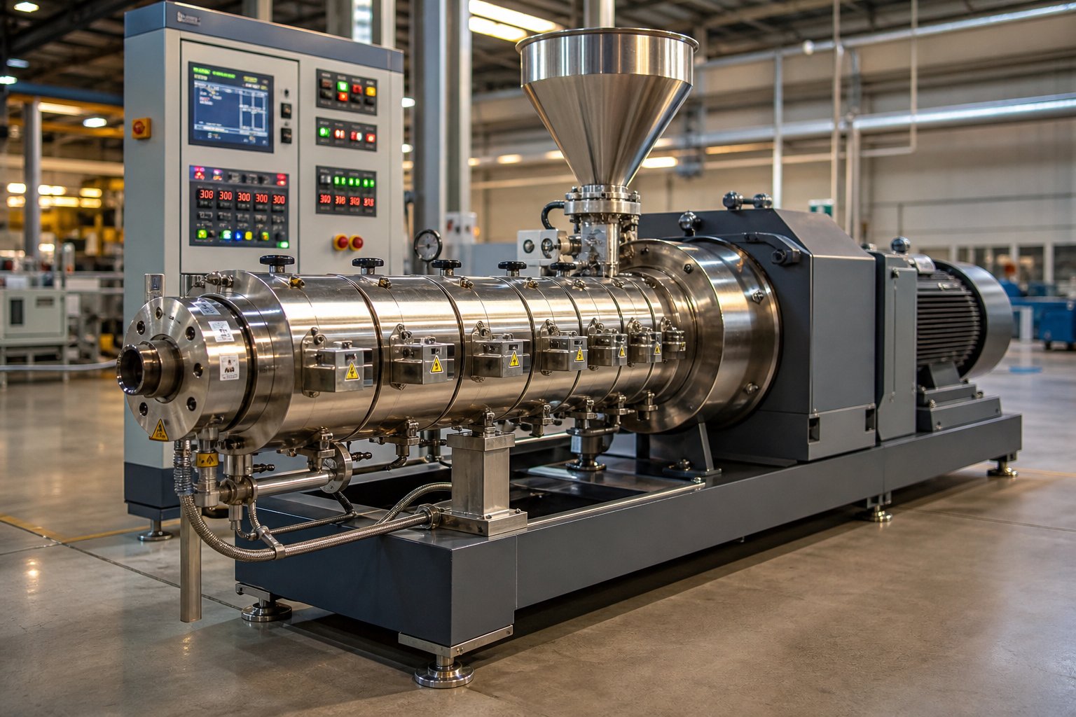
What a Twin Screw Extruder Is and Why It Dominates Modern Processing
What Is a Twin Screw Extruder
A twin screw extruder is a machine that uses two intermeshing, co-rotating or counter-rotating screws housed inside a heated barrel to convey, melt, mix, and shape polymers and other materials into a continuous output. Unlike single screw designs that rely on drag flow alone, the twin-screw extruder generates positive displacement and self-wiping action between its two screws, delivering superior distributive and dispersive mixing. This makes it the preferred technology for compounding, reactive extrusion, devolatilization, and advanced material processing across plastics, pharmaceuticals, food, and energy sectors.
Imagine feeding a handful of raw polymer pellets, fillers, and additives into one end of a machine and collecting a perfectly homogeneous, precisely formulated compound at the other. That is essentially what twin screw extruders do, thousands of times per hour, in facilities around the world. The two intermeshing screws work together to create controlled shear, thorough mixing, and consistent melt quality that batch mixers and simpler continuous devices simply cannot match.
A Brief History of Twin Screw Extrusion
The story of twin screw extrusion stretches back roughly a century. Early continuous mixing machines began appearing in patent literature during the 1920s and 1930s, initially targeting food and natural rubber applications. By the 1950s and 1960s, companies like Leistritz were producing commercial twin screw systems, though these early machines ran at far lower screw speeds and transmitted only a fraction of the torque available today. A historical review published in AAPS PharmSciTech traces how these early platforms evolved through several pivotal decades of engineering advancement.
The 1970s marked a tipping point. Much of the plastics and food industries shifted from batch processing to continuous manufacturing, primarily through twin screw extrusion. By the early 1980s, the technology had established itself as the most preferred continuous mixer for compounding. Modular barrel designs, segmented screw elements, and increasingly powerful gearboxes transformed what had been a relatively rigid machine into a flexible, reconfigurable processing platform. The Leistritz extruder, for instance, became a workhorse for both plastics compounders and, later, pharmaceutical researchers exploring melt extrusion for drug delivery.
The superior mixing characteristics inherent with a twin screw extruder have allowed this device to dominate other continuous mixers and spurred intensive development efforts that spawned highly engineered formulations for the commodity and high-tech products we use every day.
Today's modular twin screw extruders bear little resemblance to their mid-century ancestors. Shaft technologies have evolved from simple keyway designs supporting a 1.25 OD/ID ratio in the 1950s to asymmetrical splined shafts enabling ratios of 1.66 and beyond. Screw speeds exceed 1,200 rpm. Barrel metallurgies range from nitrided steels to advanced powder metallurgy alloys. And digital control systems provide real-time monitoring of every critical parameter from torque and melt temperature to specific energy input. The result is a platform that handles everything from glass-fiber-reinforced engineering plastics to sensitive pharmaceutical formulations with equal precision.
What truly sets twin screw extrusion apart, though, is not any single feature. It is the combination of modular screw design, self-wiping geometry, starve-fed operation, and short residence time that gives engineers granular control over every stage of the process. Understanding how each of those elements works together starts with a closer look at what actually happens to material as it travels from the feed throat to the die.
How a Twin Screw Extruder Works From Feed to Die
Picture raw polymer pellets, a powdered filler, and a liquid additive dropping into a feed throat. Within seconds, those three very different materials need to become a single, uniform melt stream exiting a die. The screw extruder accomplishes this transformation through a carefully orchestrated sequence of processing zones, each performing a distinct physical task. Every zone is defined by the geometry of the extruder screw elements mounted on the two intermeshing shafts, and the material encounters progressively different forces as it moves forward.
Before walking through those zones, it helps to understand the engine driving the entire process: intermeshing geometry. In a co-rotating design, the flight of one screw fits into the channel of the other, creating a C-shaped cavity that advances axially with each rotation. This produces positive displacement, meaning material is mechanically pushed forward rather than dragged by friction alone. At the same time, the flank of each screw continuously wipes the root of its partner, preventing stagnant zones where material could degrade. This self-wiping action keeps heat transfer efficient and residence time consistent from one pellet to the next.
Step-by-Step Processing Zones Along the Barrel
Although screw extrusion is a continuous process, engineers conceptualize it as a series of functional stages. Each stage can be fine-tuned independently by swapping modular screw elements, which is what makes the twin screw platform so versatile. Here is the typical sequence material follows from the extruder feed barrel opening to the die exit:
- Feeding zone — Raw materials enter through a gravimetric or volumetric feeder into the feed throat. High-pitch conveying elements with deep channels pull material in quickly, keeping the feed section starve-fed (partially filled) so that throughput is controlled by the feeder rather than the screw speed.
- Solid conveying zone — Conveying elements with progressively tighter pitch compress and transport the still-solid mixture forward. Friction between pellets, barrel wall, and screw flights begins generating mild heat, and air trapped between particles escapes through the open feed port or an atmospheric vent.
- Melting and plasticating zone — Kneading blocks replace conveying elements here. Their offset discs subject the material to intense shear and elongational flow, converting mechanical energy into heat that melts the polymer. Stagger angles of 30 to 60 degrees are common in this section, and melt fraction rises rapidly.
- Mixing and kneading zone — Once a melt phase exists, additional kneading blocks and specialized mixing elements distribute fillers and additives uniformly (distributive mixing) and break apart agglomerates (dispersive mixing). This is the heart of any compounding operation.
- Venting and devolatilization zone — Reverse-pitch conveying elements or reverse kneading blocks create a melt seal upstream of an open or vacuum vent port. The partially filled melt downstream exposes a large surface area, allowing moisture, trapped air, and volatile byproducts to escape.
- Melt conveying and pressurization zone — Tight-pitch conveying elements compress the now-homogeneous melt, building the pressure needed to push it through a downstream die, pelletizer, or other forming device.
- Die forming — The pressurized melt exits through a die that shapes it into strands, sheets, profiles, or directly into a pelletizing system. Consistent pressure from the metering zone ensures uniform extrudate dimensions.
The same twin screw hardware can behave very differently depending on which elements occupy each position. Swap a mild 30-degree kneading block for an aggressive 90-degree block, and the mixing zone transforms from gentle blending to high-shear dispersion, all without changing a single bolt on the barrel.
Free Volume Geometry and Its Impact on Throughput
If processing zones determine what happens to the material, screw geometry determines how much material can be handled and how intensely it is worked. Two geometric relationships are especially important, yet they are rarely discussed outside OEM engineering manuals.
The first is the Do/Di ratio, the outer diameter of the screw element (Do) divided by its inner diameter (Di), which is the root diameter where the element sits on the shaft. A higher Do/Di ratio, such as 1.55, 1.66, or even 1.8, means deeper screw channels and greater free volume per unit length. More free volume translates directly into higher throughput capacity and better accommodation of low-bulk-density powders or high filler loadings. A lower Do/Di ratio, around 1.45, sacrifices channel depth for a thicker shaft core, delivering higher torque-carrying capability and mechanical strength at the expense of volumetric capacity.
The second is channel depth, which is directly linked to Do/Di. Deeper channels hold more material per revolution but reduce the shear rate the melt experiences because the velocity gradient across the channel becomes less steep. Shallower channels do the opposite: they restrict volume but intensify shear, raising melt temperature and improving dispersive mixing for stubborn agglomerates.
You can think of it as a sliding scale. High Do/Di ratios favor throughput-intensive applications such as large-volume polyolefin compounding. Low Do/Di ratios favor torque-intensive applications such as processing high-viscosity engineering resins or heavily filled systems where the shaft must withstand extreme mechanical loads. Most modern extruder platforms offer at least two Do/Di options for each screw diameter, letting processors match the geometry to their specific production and formulation requirements.
These geometric choices ripple through every operating decision, from screw speed and feed rate to the type of screw elements selected for each zone. That interplay between geometry and element design becomes even more significant when comparing the two fundamental machine configurations: co-rotating and counter-rotating.
Co-Rotating vs Counter-Rotating Twin Screw Configurations
Two screws sitting side by side inside a barrel can spin in the same direction or in opposite directions. That single mechanical difference, rotation direction, cascades into dramatically different flow patterns, shear profiles, pressure capabilities, and application sweet spots. Choosing between a co-rotating and counter-rotating twin screw extruder is arguably the most consequential equipment decision a processor will make, so it pays to understand exactly what each configuration delivers.
Co-Rotating Twin Screw Extruders and Self-Wiping Action
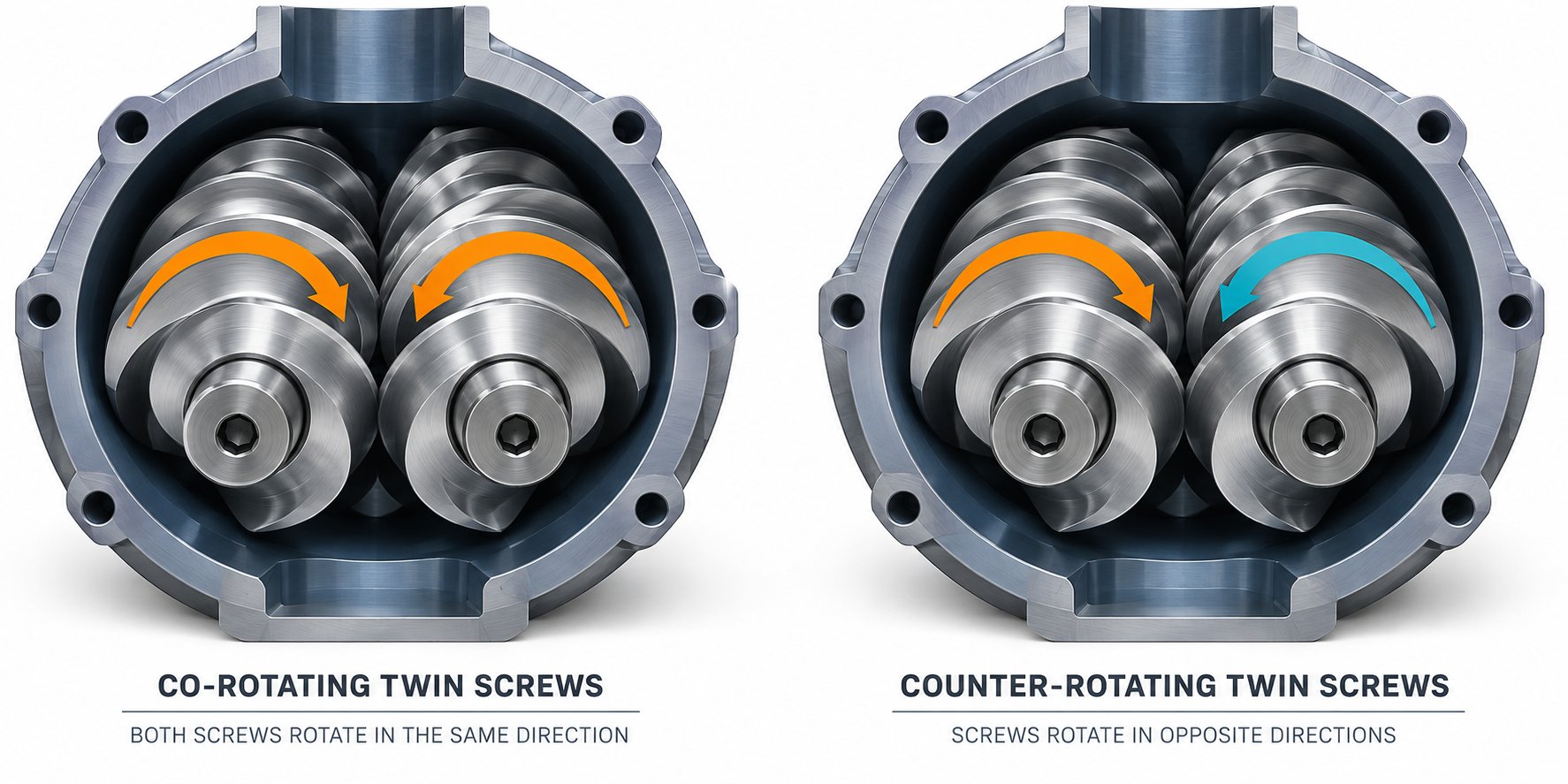
In a co-rotating twin screw extruder, both screws rotate in the same direction, either both clockwise or both counterclockwise. The screws are fully intermeshing, meaning the flight of one screw sits inside the channel of the other. As the screws turn, material traces a figure-eight path, continuously transferring from one screw to the other through the intermeshing zone. This repeated splitting, reorientation, and recombination is what gives co-rotating designs their exceptional distributive mixing.
There is another critical benefit baked into the geometry. Because the screw flights and grooves move in opposite directions at the intermeshing region, the relative velocity is high. One screw effectively wipes the surface of the other with every rotation, preventing material from stagnating and degrading. This self-wiping action keeps residence time short and uniform, a major advantage when processing thermally sensitive formulations or when rapid color changes are needed on the production floor.
The high shear rates generated in the intermeshing zone also accelerate melting and deliver strong dispersive mixing, breaking apart filler agglomerates and distributing additives at the sub-micron level. Combined with modular screw element flexibility, these characteristics explain why co-rotating machines dominate polymer compounding, masterbatch production, reactive extrusion, and devolatilization applications worldwide.
Counter-Rotating and Conical Designs for Specialized Processing
In a counter-rotating configuration, the left screw rotates clockwise while the right rotates counterclockwise, or vice versa. Material does not jump between screws in a figure-eight. Instead, it is trapped in roughly closed C-shaped chambers formed between the screw flights and the barrel wall, then pushed forward much like a gear pump. This positive displacement conveying delivers exceptional pressure stability and consistent volumetric output.
Because the two screw surfaces move in the same direction at the nip point, shear stress in the intermeshing zone is considerably lower than in a co-rotating machine. That gentler environment is exactly what heat-sensitive materials like rigid PVC need. The polymer spends less time exposed to intense mechanical energy, reducing the risk of thermal degradation and discoloration. Counter-rotating extruders have become the industry standard for PVC pipe, profile, and sheet extrusion for precisely this reason.
Counter-rotating designs come in two distinct geometric families. A parallel twin screw extruder keeps both screw diameters constant along the full barrel length, offering adjustable L/D ratios for process flexibility. A conical twin screw extruder, on the other hand, tapers from a large diameter at the feed end to a smaller diameter at the discharge end. The angled axes create a wider center distance at the big end, giving the gearbox significantly more room for robust thrust bearings and larger gear shafts. This translates into higher torque capacity and superior load-bearing capability, which is why conical designs remain popular for rigid PVC processing, especially at diameters below 80 mm where the torque advantage is most pronounced.
So which configuration wins? Neither, universally. The choice depends entirely on what you are processing and what outcome you need. The table below lays out the key performance differences side by side.
| Feature | Co-Rotating Twin Screw Extruder | Counter-Rotating Twin Screw Extruder |
|---|---|---|
| Rotation direction | Both screws same direction | Screws rotate in opposite directions |
| Intermeshing type | Fully intermeshing, self-wiping | Intermeshing or non-intermeshing |
| Typical shear rate | High (100-10,000 s-1 depending on element type and speed) | Low to moderate (50-2,000 s-1) |
| Pressure generation | Moderate; rhythmic fluctuations possible | High; stable, gear-pump-like pressure buildup |
| Self-wiping capability | Excellent; minimal material stagnation | Limited; stagnant zones possible in certain designs |
| Mixing efficiency | Superior distributive and dispersive mixing | Good dispersive mixing via calendering; lower distributive uniformity |
| Residence time distribution | Narrow and short | Broader; longer average residence time |
| Throughput flexibility | Starve-fed; throughput controlled by feeder | Often flood-fed; output tied to screw speed |
| Screw geometry | Parallel only | Parallel or conical |
| Primary applications | Compounding, masterbatch, reactive extrusion, devolatilization, nanocomposites | PVC pipes and profiles, cable coatings, direct extrusion of heat-sensitive materials |
When your process demands intense mixing, rapid formulation changes, and maximum screw configuration flexibility, a co-rotating machine is the natural fit. When stable pressure, gentle shear, and direct profile extrusion of thermally sensitive materials are the priorities, counter-rotating, whether parallel or conical, delivers results that co-rotating designs simply cannot replicate at the same operating cost.
Regardless of which configuration sits on your production floor, performance ultimately hinges on what is mounted on those shafts. The modular screw elements, conveying flights, kneading blocks, and specialized mixing discs, are where the real engineering happens.
Modular Screw Element Design and How Sequencing Affects Processing
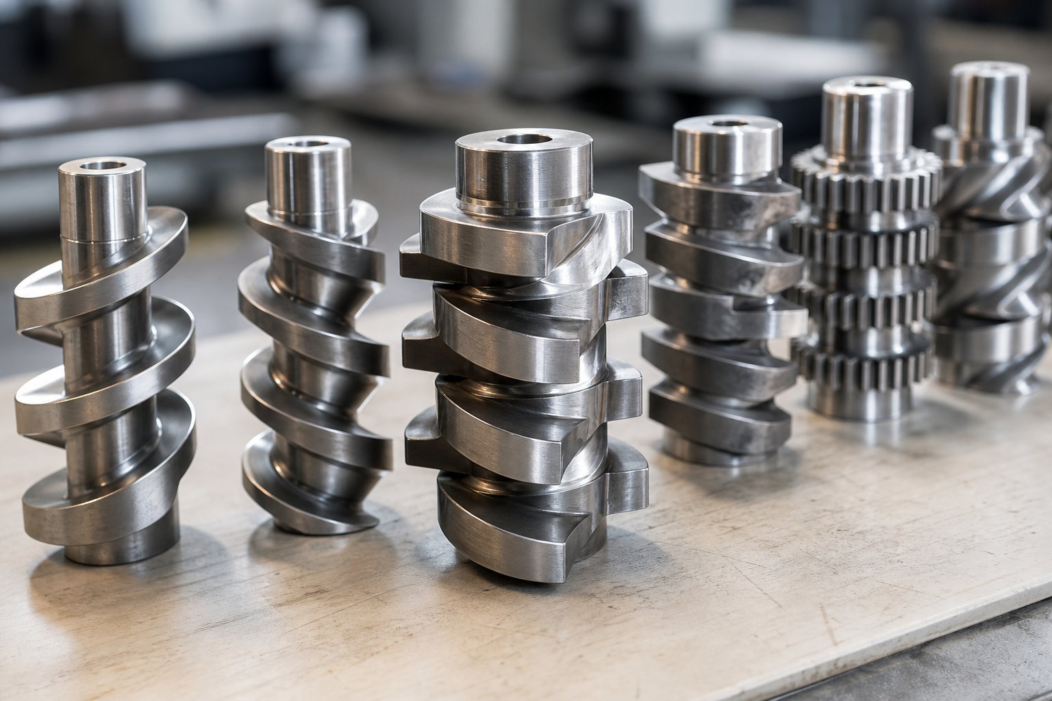
Every twin screw shaft is essentially a blank canvas. The modular "building block" system lets engineers slide individual elements onto a splined shaft in any order they choose, then rearrange them whenever a new formulation or processing goal demands a different approach. Think of it like assembling a playlist: each element is a track with a specific function, and the order you place them in determines the overall experience the material goes through. Three broad families of elements make up the toolkit, and understanding what each one does is the first step toward designing a screw profile that delivers precise results.
Conveying, Kneading, and Mixing Element Types
A well-configured extrusion screw profile draws from three element categories, each contributing a distinct processing effect. As NC State Extension research emphasizes, no gold-standard screw profile exists because every material exhibits unique flow properties, making element selection both a science and an art.
- Conveying elements (forward pitch) — These are the workhorses that move material downstream. A large-lead, deep-channel conveying element like an SK 40/40 pulls bulk material into the feed zone quickly, accommodating low-density powders and irregularly shaped pellets. As the lead shrinks, say to an SE 20/20 or SE 10/20, the element compresses the material, builds pressure, and slows down forward flow. The deeper the channel, the more volume it can transport per revolution, but with less shear imparted to the material.
- Reverse conveying elements (reverse pitch) — Designated with an "L" suffix (e.g., SE 20/20 L), these elements push material backward against the main flow. They create a dynamic restriction, a melt seal, upstream of venting ports and between processing zones. Their length is typically kept shorter than the screw diameter to prevent dangerous pressure spikes and excessive shear strain.
- Kneading blocks — The primary mixing elements on any twin screw profile. Each block consists of several offset discs stacked along the shaft at a specific stagger angle. A 30-degree forward stagger promotes gentle distributive mixing while still conveying material forward. A 60-degree stagger intensifies shear, delivering stronger dispersive action to break apart filler agglomerates. A 90-degree, or neutral, stagger provides zero forward conveying, forcing material to dwell longer under shear and dramatically increasing energy input. The width of individual discs matters too: wider kneading elements (KBW type) emphasize dispersive mixing, while narrower half-disc elements (KP type) lean toward distributive blending.
- Specialized mixing elements — Toothed mixing elements (sometimes called ZME or turbine elements) and gear-type designs fill niche roles. They deliver strong distributive mixing with minimal shear, making them ideal for blending liquid additives or heat-sensitive ingredients into a melt stream. Unlike kneading blocks, toothed elements split and recombine flow paths repeatedly without generating the high elongational stresses that can degrade sensitive polymers.
Each element type represents a different trade-off between conveying capacity, shear intensity, and residence time. The real engineering challenge is not selecting individual elements in isolation but arranging them into a coherent sequence that guides the material through a deliberate processing journey.
How Screw Element Sequencing Controls Residence Time and Shear
Imagine you are designing a plastic extrusion screw profile for a glass-fiber-reinforced nylon compound. You need aggressive melting early, thorough filler dispersion in the middle, and gentle conveying at the end to preserve fiber length. How you sequence the elements determines whether you succeed or produce an overheated, fiber-damaged mess.
A few guiding principles shape every effective profile:
Start with high-volume intake, then compress gradually. The feed section uses large-lead conveying elements to pull in bulk material without bridging. Downstream, the lead progressively decreases. As industry configuration guidelines note, small-lead elements in the melting zone build up pressure to compress and soften the polymer before any kneading blocks are introduced.
Intersperse kneading blocks with conveying elements. Stacking too many kneading blocks back to back without relief creates excessive shear, spiking melt temperature far above the setpoint. The more effective approach alternates kneading blocks and short conveying elements, distributing energy input across a longer axial distance. This keeps melt temperature controlled while still achieving thorough mixing. For enhanced mixing intensity, two-flight and three-flight kneading blocks can be combined in a single zone, blending distributive and dispersive action in one compact sequence.
Use reverse elements to create functional seal zones. Placing a short reverse element or a reverse kneading block upstream of a vent port creates a melt-filled seal. On the downstream side, large-lead conveying elements open up free volume, creating a thin melt layer with maximum exposed surface area. This arrangement is essential for efficient devolatilization, allowing moisture, air, and volatile byproducts to escape through atmospheric or vacuum vents.
Progress stagger angles deliberately. A common strategy begins with 30-degree kneading blocks for preliminary distributive mixing, advances to 45 or 60-degree blocks for stronger shear, and reserves 90-degree neutral blocks for points where maximum energy input is needed, such as just before a melt seal. Reversing this order, or placing aggressive blocks too early, risks melting the polymer unevenly and generating hot spots that degrade sensitive additives.
Reduce lead toward the die for stable output. In the final metering section, tight-pitch conveying elements build discharge pressure while single-flight or wide-flight designs maximize volumetric pumping efficiency, preventing melt overflow and ensuring dimensional consistency in the extrudate.
The beauty of twin screws equipped with modular elements is that none of these choices are permanent. If a trial run reveals insufficient dispersion, you can pull the screws, swap a 30-degree kneading block for a 60-degree block in the mixing zone, and retest within a shift. That iterative flexibility, absent from any fixed-geometry single-screw design, is ultimately what makes screw element sequencing the most powerful tuning tool in a compounder's arsenal.
Knowing how to build the right screw profile is one thing. Knowing whether your machine should have twin screws or a single screw in the first place is another, and the performance gap between the two designs is wider than many newcomers expect.
Twin Screw Extruder vs Single Screw Extruder Compared
The performance gap between a double screw extruder and a single screw design is wider than a spec sheet might suggest. On paper, both machines rotate helical flights inside a heated barrel to melt and convey polymer. In practice, the underlying transport mechanism, mixing physics, and economic trade-offs diverge so sharply that choosing the wrong type can mean the difference between a profitable compounding line and one that bleeds waste, energy, and downtime.
A single screw extruder is fundamentally a drag-flow device. Material advances because friction between the pellets, the barrel wall, and the screw flight drags it forward. That works well for straightforward melting and forming of homogeneous resins, but it also means output is sensitive to friction coefficients, melt viscosity, and barrel-surface condition. An extruder twin screw system, by contrast, uses positive displacement: the two intermeshing screws physically trap and push material forward regardless of friction, giving processors far tighter control over throughput and residence time.
Mixing and Shear Performance Differences
Sounds like a subtle mechanical distinction? The downstream consequences are anything but subtle. In a single screw channel, mixing happens almost as an afterthought. The polymer tumbles in a helical flow path, relying on chaotic recirculation for whatever blending occurs. Dispersive mixing, the kind needed to break apart pigment agglomerates or glass-fiber bundles, is minimal unless specialized static mixers or barrier flights are added. Research into extensional mixing elements has improved single screw dispersion in recent years, but these solutions address individual deficiencies rather than matching the full mixing environment a twin screw provides.
A double screw extruder machine, meanwhile, generates both distributive and dispersive mixing simultaneously across every kneading block and mixing element. Material splits, reorients, and recombines in an exponential layer-multiplication pattern that ensures additives are uniformly distributed even at very low concentrations. Residence time approximates plug flow with minimal back-mixing, so every granule receives the same thermal and mechanical history. Temperature control is tighter too: the constant stirring action between intermeshing screws eliminates the stagnant zones that cause localized overheating and viscosity instabilities in single screw channels.
Cost, Maintenance, and When Each Type Makes Sense
Superior mixing comes at a price. Industry pricing data shows twin screw models ranging from roughly $20,000 for lab-scale units to $800,000 for large industrial machines, with most medium-capacity systems falling between $80,000 and $300,000. Single screw extruders typically range from $50,000 to $150,000. Installation can add another 10-30% to the twin screw purchase price due to more complex drive systems and ancillary equipment.
Maintenance follows a similar pattern. Twin screw systems have more components, tighter tolerances between intermeshing elements, and modular assemblies that require skilled technicians for screw changeovers. Single screw machines are simpler to operate, faster to train staff on, and cheaper to maintain. Energy consumption tilts toward twin screws as well, since dual-drive systems and higher shear forces draw more power per hour of operation.
Yet the cost-per-kilogram picture often reverses for complex formulations. When you factor in reduced scrap rates, fewer off-spec batches, faster changeovers enabled by self-cleaning action, and the ability to consolidate multiple processing steps into a single pass, the twin screw frequently delivers a lower total cost of ownership. A single screw extruder remains the smarter investment for dedicated, high-volume production of simple products like mono-material pipe, film, or sheet where intensive mixing is unnecessary.
The table below condenses these trade-offs into a side-by-side reference.
| Dimension | Twin Screw Extruder | Single Screw Extruder |
|---|---|---|
| Transport mechanism | Positive displacement via intermeshing screws | Friction-driven drag flow |
| Mixing capability | High; both dispersive and distributive mixing | Low to moderate; primarily chaotic recirculation |
| Typical shear rate range | 100 - 10,000 s-1 | 20 - 200 s-1 |
| Throughput flexibility | Starve-fed; independent control of feed rate and screw speed | Flood-fed; output coupled to screw speed |
| Residence time control | Narrow distribution; near plug flow | Broad distribution; back-mixing common |
| Self-cleaning ability | Excellent; self-wiping intermeshing geometry | None; manual purging required |
| Pumping efficiency | ~100% volumetric efficiency | 40-60% (pressure-dependent) |
| Capital cost | Higher ($20K - $800K depending on scale) | Lower ($50K - $150K typical range) |
| Maintenance complexity | Higher; modular elements, tighter tolerances, skilled labor | Lower; fewer components, simpler service |
| Energy consumption | Higher due to dual drives and elevated shear | Lower; single motor, less mechanical work input |
| Ideal applications | Compounding, masterbatch, reactive extrusion, recycling, devolatilization | Mono-material pipe, film, sheet, profile extrusion |
The takeaway is straightforward: match the machine to the mission. If your process involves blending multiple components, dispersing fillers, removing volatiles, or frequent recipe changes, a twin screw system justifies its premium. If you are running a dedicated line producing millions of meters of the same pipe or film, a single screw extruder will do the job at lower capital and operating cost. Most mid-to-large plastics operations end up running both types, each assigned to the applications where it excels.
Selecting the right machine category is only half the equation, though. Even the best-suited extruder will underperform if the operating parameters feeding it, screw speed, barrel temperatures, feed rate, and torque limits, are not dialed in correctly and monitored continuously.
Operating Parameters and Troubleshooting for Optimal Performance
A perfectly configured screw profile and the right machine category still will not save a process if the operating parameters are off. Screw speed, barrel temperatures, feed rate, torque, and L/D ratio form an interlocking web of variables, and adjusting any single one ripples through the others. Engineers who master these interactions can push a twin screw extruder machine to its full potential. Those who treat each knob in isolation end up chasing problems that keep circling back.
Critical Operating Parameters and How They Interact
Every parameter on the control panel influences the material in a different way, but none of them acts alone. Here is what each one controls and how it connects to the rest of the extruder system:
- Screw speed (rpm) — Directly governs shear rate, mechanical energy input, and the conveying velocity of material through the barrel. Increasing screw speed accelerates melting and intensifies dispersive mixing, but it also raises melt temperature through frictional heating and shortens residence time. Typical production-scale machines operate anywhere from 200 to 1,200 rpm depending on formulation sensitivity. Industry data on commercial extruders shows maximum speeds ranging from roughly 520 rpm on smaller models to over 600 rpm on mid-range platforms, with high-speed compounders pushing well beyond that.
- Barrel temperature profile — Set independently across multiple heating and cooling zones from the feed throat to the die. A well-designed profile typically ramps up through the melting zones, holds steady or slightly decreases through the mixing section, and drops in the final metering zone to control melt viscosity at the die. Barrel temperatures should be viewed as guardrails rather than absolute melt temperatures: the actual resin temperature results from the combined effect of barrel heat transfer and viscous dissipation from the screws. Most modern systems maintain zone accuracy within ±2 °C using PID-controlled heater bands and liquid cooling jackets.
- Feed rate (kg/h) — Controls throughput independently of screw speed because twin screw systems operate starve-fed. The ratio of feed rate to screw speed, often expressed as Q/N (throughput divided by screw speed), determines the degree of fill inside the barrel. A higher Q/N increases the fill ratio in partially filled conveying sections, extending residence time and intensifying mixing. A lower Q/N reduces fill, shortening thermal exposure but potentially starving kneading zones of enough material for effective dispersion. Experiments on instrumented extruders confirm that identical Q/N values produce comparable fill states regardless of absolute throughput, making Q/N a powerful parameter for process transfer and scale-up.
- Torque (%) — Reflects the mechanical resistance the screws encounter as they work the material. Torque is the single best real-time indicator of process load. A rising torque trend suggests increasing melt viscosity, higher fill, or a developing blockage. Most control systems display torque as a percentage of the gearbox rating, and operators should keep it below 80-85% during steady-state operation to protect the drive train. Exceeding rated torque triggers automatic shutdowns on well-designed machines.
- L/D ratio (length-to-diameter ratio) — A fixed machine specification, not an in-process variable, but one that shapes every other parameter decision. Standard compounding and extrusion applications typically use L/D ratios of 32:1 to 48:1. Longer barrels provide more processing zones and therefore more residence time, additional vent ports, and room for downstream side feeding of fillers or fibers. Shorter L/D ratios, around 24:1 to 28:1, suit simpler blending tasks or heat-sensitive materials that benefit from minimal thermal exposure.
Here is where these interactions become practical. Imagine you increase screw speed to boost throughput on a compounding line. Shear rate climbs, melt temperature rises, and residence time drops. If the kneading zone no longer has enough time to disperse your filler, you can compensate by raising the feed rate proportionally to maintain the same Q/N and fill state, but that increases torque. If torque approaches the gearbox limit, you may need to lower the barrel temperature in the melting zone to reduce viscosity, or swap a 90-degree kneading block for a 60-degree alternative to ease the mechanical load. Every adjustment triggers a chain reaction. Successful operators learn to anticipate these cascading effects rather than react to them one at a time.
Troubleshooting Common Twin Screw Extruder Problems
Even experienced operators encounter process upsets. The difference between a quick recovery and hours of lost production often comes down to systematic diagnosis. The table below maps the most frequent symptoms to their probable causes and recommended corrective actions, drawn from field troubleshooting experience across compounding and masterbatch operations.
| Problem | Probable Cause | Recommended Action |
|---|---|---|
| Output surging (fluctuating strand diameter or pellet weight) | Inconsistent feed rate due to hopper bridging, worn feeder auger, or gravimetric feeder drift | Inspect hopper for material bridges; recalibrate the feeder with actual production material; check feed throat cooling to prevent premature melting (maintain 20-40 °C) |
| Excessive torque or motor overload | Overfeeding relative to screw speed, high melt viscosity, material buildup or blockage in barrel or die, insufficient barrel temperature in melting zone | Reduce feed rate and screw speed simultaneously; verify barrel temperatures match the resin's recommended processing window; inspect die and screen changer for blockages; check gearbox lubrication |
| Discoloration or material degradation | Excessive melt temperature from high shear input, stagnant material in dead zones, moisture in feed stock, or barrel temperature set too high | Lower screw speed or reduce aggressive kneading block count; verify material is pre-dried to below 0.05% moisture; inspect screw elements for wear-related dead spots; reduce barrel temperature in overheating zones |
| Die drool (material accumulation at die lips) | Molecular weight degradation causing low-viscosity melt fraction, excessive volatile content, or die temperature too high | Reduce melt temperature through lower screw speed or barrel setpoints; add or improve vacuum venting upstream of the die; clean and polish die lips; verify resin lot consistency |
| Barrel or screw element wear (increasing torque trend, declining product quality over time) | Processing abrasive fillers (glass fiber, mineral fillers, recycled material with contaminants) with inadequate metallurgy; screw-to-barrel clearance exceeds 0.2 mm | Measure screw outer diameter and barrel bore at multiple points; replace worn elements; upgrade to wear-resistant metallurgy (bimetallic barrels, powder metallurgy screw elements) for abrasive formulations |
| Vent flooding (material exiting through vent ports) | Insufficient melt seal upstream of vent, excessive fill ratio in the vent zone, or screw speed too low relative to feed rate | Verify that reverse elements or reverse kneading blocks upstream of the vent are creating an adequate melt seal; reduce Q/N by lowering feed rate or increasing screw speed; check that vent port is not obstructed |
A pattern runs through nearly every row: the root cause traces back to an imbalance among the core operating parameters discussed above. Output surging links to feed rate instability. Torque overload links to the Q/N ratio being too high. Degradation links to excessive shear energy. Systematic troubleshooting, in other words, starts by asking which parameter relationship has drifted out of its target window, rather than treating each symptom as an isolated event.
Of course, parameter optimization can only compensate so far if the hardware itself is failing. Barrel metallurgy, screw element materials, and drive system capacity define the physical ceiling on what any set of process conditions can achieve, and those hardware choices deserve their own careful evaluation.
Critical Components and How Specifications Drive Longevity
Barrel metallurgy, screw element alloys, and drive system torque ratings are not line items to gloss over on a purchase order. They are the variables that determine whether your extruder screw barrel assembly delivers five years of reliable throughput or starts leaking performance after six months. A machine running glass-fiber-reinforced nylon at 40% filler loading subjects its internals to an environment roughly comparable to sandblasting, hour after hour, shift after shift. The wrong material choice does not just shorten part life; it contaminates product, destabilizes melt quality, and generates unplanned downtime that cascades through the entire production schedule.
Most component guides stop at naming the parts. What matters far more is understanding why one barrel liner outperforms another in a specific application, and how screw element metallurgy interacts with processing parameters to either extend or destroy service intervals. That understanding starts inside the barrel wall.
Barrel Metallurgy and Wear Protection Strategies
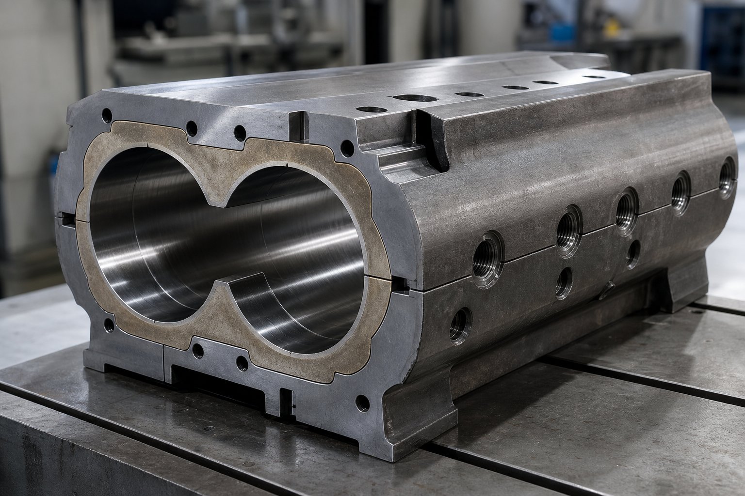
The twin screw barrel is not a passive tube. It absorbs enormous compressive forces, conducts heat into and away from the melt, and presents the primary wear surface against which abrasive fillers grind with every screw rotation. Barrel inner-surface hardness, coating depth, and corrosion resistance dictate how long the bore maintains its original dimensional tolerance, and once clearance between the screw flight tip and the barrel wall opens beyond roughly 0.2 mm, mixing efficiency drops, specific energy input rises, and product consistency deteriorates.
Three broad tiers of barrel protection exist, each suited to a different severity of service:
Nitrided steel barrels represent the entry point. Base steels such as 38CrMoAlA or 42CrMo are gas- or plasma-nitrided to produce a hardened surface layer approximately 0.5 to 0.8 mm deep. This treatment is cost-effective and entirely adequate for general-purpose compounding with unfilled or lightly filled polymers, color concentrates, and thermoplastic elastomers. Industry field data suggests nitrided barrels typically deliver one to two years of service life when processing moderately filled materials before wear reaches replacement thresholds.
Bimetallic lined barrels step up dramatically in abrasion resistance. A centrifugally cast or inlaid liner of wear-resistant alloy, commonly nickel-based grades like Ni60 or specialty alloys such as X800, is metallurgically bonded inside the barrel bore. The result is a thick, uniformly hard inner surface that resists the cutting action of glass fibers, calcium carbonate, talc, and other mineral fillers far longer than a nitrided surface can. Bimetallic twin screw barrel assemblies cost roughly 30 to 50% more than nitrided equivalents, but they routinely last two to three times longer under heavy abrasive loading, making them the lower total-cost option for high-filler operations.
Tungsten carbide coatings occupy the extreme end of the protection spectrum. Applied via high-velocity oxygen fuel (HVOF) thermal spray or similar processes, these coatings create an exceptionally hard surface capable of withstanding the most aggressive abrasive and erosive conditions. They are typically reserved for processing lines running very high mineral filler concentrations, recycled material streams containing metal contaminants, or ceramic-loaded specialty compounds where even bimetallic liners wear too quickly.
For compounding plants, pelletizing lines, masterbatch producers, and recycling operations that demand stable mixing and conveying over extended campaigns, barrel durability becomes a make-or-break factor. NANHAIYA's parallel twin screw barrel is one example of a barrel solution engineered specifically for these high-wear processing environments, offering metallurgical options designed to maintain bore integrity under sustained abrasive and thermal stress.
Regardless of supplier, the evaluation criteria remain the same. When specifying a twin screw and barrel assembly for a new line or a replacement order, these are the factors that should drive your decision:
- Filler type and loading level — Glass fiber, calcium carbonate, talc, and recycled-stream contaminants each present different wear profiles. Match the liner alloy to the dominant abrasive mechanism.
- Corrosion exposure — Halogenated polymers like PVC release hydrochloric acid during processing. Flame-retardant additives can generate similarly corrosive byproducts. Corrosion-resistant liner alloys or stainless steel barrel construction may be necessary.
- Bore surface finish — A smoother bore (Ra 0.4 μm or better) reduces material adhesion, minimizes dead spots, and improves color-change speed. Verify the manufacturer's finishing specification before purchase.
- Dimensional tolerance — The clearance between screw flight OD and barrel bore determines sealing, mixing, and self-wiping efficiency. Tighter tolerances demand higher manufacturing precision but deliver better initial performance.
- Cooling channel design — Barrel zones must remove heat efficiently to prevent thermal runaway. Evaluate the number, placement, and diameter of internal cooling channels, especially in zones downstream of intensive kneading sections.
- Modularity and replacement lead time — Segmented barrel designs allow individual sections to be swapped without replacing the entire assembly. Confirm that your barrel supplier stocks or can rapidly manufacture replacement sections for your specific extruder screw and barrel configuration.
Screw Element Materials and Drive System Considerations
The barrel absorbs wear from the outside in, but screw elements face equally punishing conditions from the opposite direction. Every kneading block tip, every conveying flight crest, and every mixing element tooth contacts abrasive material at high velocity and elevated temperature. When screw elements wear, flight tips lose their sharp geometry, clearances open up, and the self-wiping action that keeps a twin screw extruder clean and efficient degrades progressively.
Standard screw elements are typically machined from through-hardened tool steels such as W6Mo5Cr4V2 (a high-speed steel grade common across many OEM platforms), heat-treated to 58-62 HRC. This provides a solid baseline of wear resistance and toughness for general compounding. Field experience with high-speed compounding extruders confirms that standard tool steel elements handle moderate filler concentrations of 10 to 30% calcium carbonate at acceptable wear rates, roughly 0.5 to 1.0 mm per year of continuous operation.
Push the filler loading above 30%, switch to glass fiber reinforcement, or introduce recycled streams with metallic contaminants, and standard tool steels fall short. This is where powder metallurgy (PM) alloys justify their premium. Grades like ASP 2052 and similar PM high-speed steels are produced through atomization and hot isostatic pressing, creating an exceptionally fine, uniform carbide distribution throughout the material. The result is two to three times the abrasive wear resistance of conventional tool steels, along with improved toughness that resists chipping under impact loads from hard filler particles. PM elements typically add 50 to 80% to per-element cost, but they can double or triple service intervals, reducing the frequency of production stops for screw changeovers and the associated lost output.
Surface coatings offer an alternative or complement to upgraded base materials. Plasma nitriding hardens screw element surfaces to 65-70 HRC, extending life by roughly 1.5 to 2 times in abrasive applications. PVD coatings such as chromium nitride (CrN) or titanium nitride (TiN) reach hardness values of 2,000 to 3,000 HV and are particularly effective at reducing adhesive wear with sticky polymers like polyamide or PVC. For the most severe abrasive conditions, tungsten carbide thermal-spray coatings on screw elements provide the ultimate wear barrier, though at a significantly higher treatment cost.
None of these material upgrades matter if the drive system cannot deliver the torque and speed the process demands. The drive system, motor, gearbox, and shaft assembly, defines the mechanical energy ceiling for the entire extruder. Industry experts note that the cross-sectional area of the screw shafts, combined with shaft design and metallurgy, determines the maximum torque that can be applied to the process. An undersized gearbox forces operators to run at higher screw speeds to achieve target throughput, which accelerates wear across every element and barrel section. Selecting a drive with adequate torque density, the torque available per unit of shaft cross-sectional area, lets processors operate at lower speeds for the same output, reducing shear heating and extending the service life of the entire extruder screw barrel assembly.
A practical rule of thumb: if your process routinely operates above 80% of rated torque, you are consuming your safety margin and accelerating mechanical fatigue. Specifying a drive system with 20 to 30% torque headroom above the expected process load provides the flexibility to handle formulation variations, viscosity spikes from lot-to-lot resin changes, and the inevitable increase in drag as screw and barrel surfaces wear over time.
Barrel metallurgy, element alloys, and drive capacity form a triangle of interdependent choices. Upgrade one leg without addressing the others, and the weakest link still dictates your maintenance schedule and product quality ceiling. Getting all three right unlocks the full performance envelope of the machine, which becomes especially important as processors push twin screw technology into applications far beyond traditional polymer compounding.
Industrial Applications From Compounding to Advanced Manufacturing
Barrel metallurgy and screw element alloys only matter if the machine is doing meaningful work, and the range of work twin screw extruders now perform stretches far beyond their polymer compounding roots. The same platform principles that made the technology indispensable for plastics processing are opening doors in energy storage, pharmaceutical production, sustainability, and food science. Here is where that versatility plays out across both established and frontier applications.
Established Polymer Compounding and Masterbatch Applications
Polymer compounding remains the bedrock application. A twin screw compounding extruder takes virgin resin, blends it with stabilizers, pigments, flame retardants, or reinforcing fibers, and produces a homogeneous pellet ready for downstream molding or extrusion. Every engineering plastic on the market, from glass-filled nylon to impact-modified polycarbonate, passes through a compounding extruder at some point in its lifecycle. The intense distributive and dispersive mixing, combined with precise temperature and residence time control, ensures that additives reach their target dispersion at concentrations sometimes as low as 0.1%.
Masterbatch production follows the same principle at higher additive concentrations. Color masterbatch, for instance, may contain 40 to 70% pigment by weight. Achieving uniform pigment dispersion at those loadings without degrading the carrier resin demands the kind of shear-controlled kneading environment only a twin screw extruder plastic compounding line can deliver. Filled and reinforced compound production pushes hardware even harder: 50% glass fiber in polypropylene or 60% calcium carbonate in polyethylene challenges every component from barrel liners to screw element metallurgy, which is exactly why the material selection principles discussed earlier matter so much in practice.
PVC processing, whether rigid pipes or flexible cable sheathing, is another stronghold. Counter-rotating extruders handle the heat sensitivity of PVC formulations with the gentle shear and stable pressure profiles these materials require. Taken together, these traditional applications still account for the vast majority of installed twin screw capacity worldwide.
Emerging Applications in Energy, Pharma, and Sustainable Processing
What is remarkable about the last decade is how rapidly the technology has expanded beyond traditional plastics. The modular design, continuous flow path, and precise control over shear and thermal history make a twin screw extruder an ideal platform for process-intensive applications across entirely different industries.
- Battery electrode slurry manufacturing — Lithium-ion battery production requires uniform dispersion of active materials, conductive additives, and binders into a viscous slurry. Twin screw systems deliver the consistent distributive mixing needed to eliminate agglomerates that cause defects in coated electrode films, all in a continuous process that scales more predictably than batch mixers.
- Continuous pharmaceutical manufacturing — The FDA's promotion of Quality by Design (QbD) and Process Analytical Technology (PAT) frameworks has accelerated pharmaceutical adoption of twin screw extrusion. As an integrated, continuous platform, it minimizes batch-to-batch variation, supports real-time monitoring, and produces granules with improved properties for oral solid dosage forms. More than three decades of research have validated its role in hot-melt extrusion for drug delivery and twin screw granulation for tablet manufacturing.
- Recycling and upcycling of post-consumer plastics — Mixed-stream plastic recycling demands aggressive devolatilization, contaminant tolerance, and the ability to blend recycled resins with virgin material or compatibilizers. The self-wiping geometry and modular venting capability of co-rotating systems make them the extruder for polymer recycling lines where feedstock quality varies from batch to batch.
- 3D printing filament production — Consistent filament diameter and homogeneous material properties are non-negotiable for reliable additive manufacturing. Recent research into upcycling waste plastics demonstrates that post-consumer HDPE can be co-extruded with glass fibers through twin screw systems to produce reinforced filaments with tensile strength improvements of up to 95%, turning plastic waste into high-performance 3D printing feedstock. Twin screw extruder plastic processing expertise translates directly into this emerging market.
- Food-grade extrusion — This is where the technology reveals perhaps its most surprising versatility. Twin screw extrusion serves as a physical modification method that applies intense mechanical force, pressure, and heat to transform raw ingredients into finished food products. Studies on heat-moisture extrusion of protein-fortified flour show that during the process, starch granules gelatinize while protein structures unfold and cross-link, forming network structures that improve water absorption, oil absorption, and thermal stability of the final product. Controlling three variables simultaneously, moisture content (typically 20-35%), cooking temperature (80-160 degrees C), and residence time (30-90 seconds), determines whether the extrudate emerges as a puffed snack, a texturized vegetable protein, or a modified starch ingredient. Screw speed also plays a defining role: the referenced research found that moderate extrusion temperatures and screw speeds produced the best network structures, while excessive conditions destroyed both starch crystallinity and protein cross-links. This sensitivity to process parameters makes the modular, precisely controllable nature of the compounding twin screw extruder especially valuable for food applications.
Across all of these domains, the common thread is the same: twin screw extrusion provides continuous, scalable, and precisely controllable processing that batch methods struggle to match. The technology's expansion into pharmaceuticals, batteries, and food underscores a reality that the polymer industry has known for decades: when your process demands intimate mixing under tightly controlled conditions, two intermeshing screws inside a modular barrel remain the most effective engineering solution available.
Yet moving from a successful laboratory trial in any of these applications to full-scale production introduces a new set of engineering challenges. Geometry changes, heat transfer dynamics shift, and process parameters that worked perfectly on a 26 mm extruder do not simply copy over to a 92 mm machine. Navigating that scale-up pathway, and selecting the right equipment to match your specific requirements, requires its own systematic approach.
Scaling Up and Selecting the Right Twin Screw Extruder
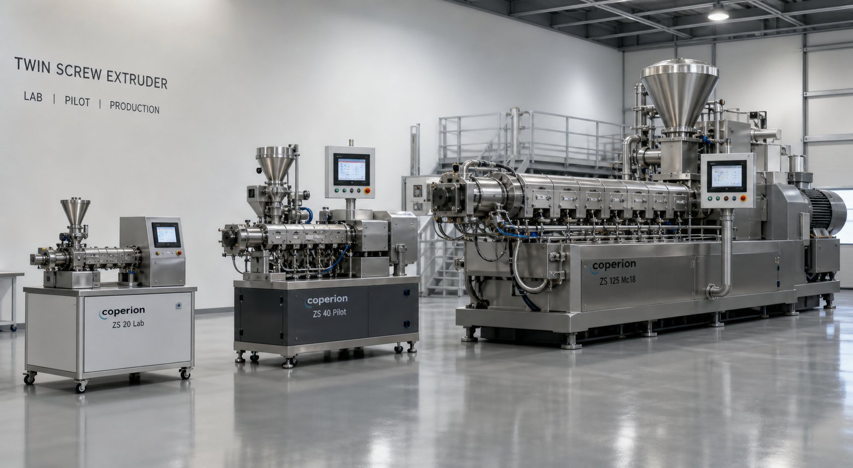
A formulation that runs beautifully on a 20 mm laboratory twin screw extruder does not automatically behave the same way on a 92 mm production machine. Barrel diameter quadruples, free volume increases by a factor of roughly 45, and heat transfer dynamics shift from surface-dominated cooling to bulk-dominated retention. Misunderstanding what changes during scale-up, and what must stay constant, is one of the fastest ways to turn a promising lab result into a costly production failure.
Scale-up and equipment selection are really two sides of the same coin. The pathway from bench to plant defines the specifications you need, and the specifications you choose determine whether that pathway delivers reliable results or expensive surprises.
Scaling From Laboratory to Pilot to Full Production Extruders
The journey typically follows three stages: a lab scale extruder for initial feasibility and formulation screening, a pilot-scale machine for process validation and customer sampling, and a full-production system for commercial output. Each stage answers different questions. The laboratory scale extruder, usually 16 to 26 mm in screw diameter with throughput below 50 kg/h, tells you whether a formulation can work. A pilot system, typically 30 to 50 mm, tells you how it will work at relevant volumes. The production extruder, 50 mm and above, tells you how efficiently it works at commercial scale.
What makes scale-up tricky is that some parameters scale predictably while others do not. Barrel surface area grows with the square of diameter, but free volume grows with the cube. That means a larger machine generates more viscous dissipation per unit of cooling surface, making melt temperature harder to control. Specific mechanical energy (SME), the energy input per kilogram of material, is the single most reliable bridge between scales, but matching it requires careful adjustment of screw speed and feed rate on the larger machine.
A systematic approach reduces the guesswork:
- Establish baseline SME on the laboratory extruder — Record torque, screw speed, and throughput during optimized runs. Calculate SME (kWh/kg) as your primary scale-up anchor.
- Maintain geometric similarity — Use the same Do/Di ratio, L/D ratio, and screw element sequence on the pilot and production machines. Geometric similarity ensures comparable shear rates and residence time distributions at each scale.
- Scale screw speed using tip speed equivalence — Rather than matching rpm directly, match the circumferential velocity at the screw tip (tip speed = pi x Do x N). This preserves the shear rate at the barrel wall, which is the dominant factor in melt temperature rise and dispersive mixing intensity.
- Adjust feed rate to maintain degree of fill — The Q/N ratio (throughput divided by screw speed) that produced optimal fill and mixing on the lab machine should be preserved on the larger system. Holding Q/N constant keeps the partially filled and fully filled zones in the same proportional positions along the barrel.
- Validate thermal profiles and adjust barrel cooling — Larger barrels have lower surface-to-volume ratios, so melt temperatures tend to run hotter. You may need to reduce barrel setpoints or increase cooling capacity in the mixing zones. Monitor actual melt temperature at the die, not just barrel zone readings.
- Confirm product quality against lab-scale benchmarks — Run standard characterization tests (MFI, tensile properties, dispersion quality, color values) on production samples and compare directly to lab-scale data. Deviations point to scale-up parameters that need further adjustment.
A benchtop twin screw extruder with 20 to 25 mm screws and an L/D of 40:1 often provides the best balance of low material consumption and meaningful scale-up data. Models in this range typically require only 2 to 15 kg/h of material per run, making them ideal for iterating through dozens of formulation variants without burning through expensive resins. Many research institutions and corporate R&D centers treat these compact systems as their primary process development tools, running feasibility studies and generating the SME and residence time data that guide every subsequent scale-up decision.
Pilot-scale machines in the 30 to 50 mm range bridge the gap to production. They produce enough material for customer qualification samples, downstream injection molding trials, and limited commercial runs while still operating in a controlled development environment. The cost difference is significant: a lab twin screw extruder in the 20 to 25 mm range typically falls between $18,000 and $45,000, while pilot systems run $45,000 to $75,000 or more depending on configuration. Production-class machines start around $80,000 and can exceed $800,000 for large-diameter, high-torque systems.
How to Select the Right Twin Screw Extruder for Your Application
Whether you are evaluating a twin screw extruder for sale from an established OEM or comparing offerings across multiple twin screw extruder manufacturers, the selection process benefits from a structured decision framework. Price is easy to compare; capability fit is harder. These are the dimensions that matter most:
1. Define your application requirements first. List your top five target products and their specific processing demands: filler type and loading percentage, polymer melt temperature range, required throughput in kg/h, devolatilization needs, and any reactive chemistry. A machine optimized for 30% glass-fiber-reinforced PA6 has fundamentally different torque, metallurgy, and feeding requirements than one designed for color masterbatch or unfilled TPE. As industry selection guides emphasize, a mismatch between application requirements and machine specifications is the most common cause of project failure.
2. Match diameter and L/D ratio to throughput and process complexity. Larger screw diameters deliver higher throughput but cost proportionally more and demand greater motor power. Standard L/D ratios of 40:1 to 44:1 handle most compounding applications. Reactive extrusion or multi-stage devolatilization may justify 48:1 to 60:1, while simpler blending tasks can work with 32:1 to 36:1. Over-specifying L/D increases capital cost, floor space, and residence time, which can degrade heat-sensitive materials.
3. Verify torque and power ratings against worst-case formulations. Torque determines whether the machine can handle your most viscous or most heavily filled product without tripping on overload. High-torque gearboxes rated at 10 to 12 Nm/cm3 are essential for engineering plastics and high-filler compounds. Under-specifying torque leads to chronic production interruptions and potential material degradation inside the barrel.
4. Evaluate barrel and screw metallurgy for your filler profile. This is where many buyers underinvest. If your product portfolio includes glass fiber, mineral fillers, or recycled material streams with abrasive contaminants, standard nitrided barrels will wear through in months. Bimetallic lined barrels and powder metallurgy screw elements dramatically extend service life and lower total cost of ownership. When evaluating barrel suppliers, look for solutions engineered specifically for high-wear processing. NANHAIYA's parallel twin screw barrel, for instance, targets the durability demands of compounding plants, pelletizing lines, masterbatch producers, and recycling operations where stable mixing and conveying performance over extended campaigns is non-negotiable. Assess liner alloy options, bore surface finish, cooling channel design, and replacement lead times before committing.
5. Assess the screw element library and modularity. A supplier with a limited range of kneading block angles and mixing element types limits your future product development flexibility. Confirm availability of 30, 45, 60, and 90-degree kneading blocks, toothed mixing elements, and specialized conveying elements for fiber feeding or liquid injection.
6. Examine control system capability and data acquisition. Recipe storage, real-time torque and pressure monitoring, data logging for ISO compliance, and remote access for troubleshooting support are no longer luxuries. The cost difference between a basic analog control panel and a fully integrated PLC/SCADA system is typically $10,000 to $15,000, but the reduction in operator error and scrap rates usually pays for itself within the first year.
7. Budget for the entire line, not just the extruder. Feeders, pelletizers, cooling systems, and material handling equipment typically add 1.5 to 2 times the extruder price. A machine capable of 500 kg/h is worthless if the pelletizer downstream can only handle 400 kg/h. Ensure every component in the line is capacity-matched.
8. Demand material trials before purchase. Reputable twin screw extruder manufacturers offer application laboratories where you can run your actual formulation on the proposed machine before signing a purchase order. A supplier who refuses material testing is a red flag. Trial runs validate mixing performance, confirm throughput targets, and generate the process data you will need for production startup.
Ultimately, the right machine is not the cheapest one or the most powerful one. It is the one whose diameter, torque, metallurgy, modularity, and control precision align precisely with what your materials demand today and what your product roadmap will require over the next 15 to 20 years. Take the time to define your requirements rigorously, run trials with real materials, and evaluate total cost of ownership rather than purchase price alone. That disciplined approach transforms the selection process from a gamble into an engineering decision, one that will pay dividends across every kilogram of compound the machine produces.
Frequently Asked Questions About Twin Screw Extruders
1. What is the difference between a co-rotating and counter-rotating twin screw extruder?
A co-rotating twin screw extruder has both screws spinning in the same direction with fully intermeshing, self-wiping geometry. This produces high shear rates (100-10,000 s⁻¹), excellent distributive and dispersive mixing, and narrow residence time distribution, making it ideal for compounding, masterbatch, and reactive extrusion. A counter-rotating extruder has screws turning in opposite directions, creating closed C-shaped chambers that act like a gear pump. It delivers lower shear (50-2,000 s⁻¹), stable pressure buildup, and gentler processing suited for heat-sensitive materials like rigid PVC. Counter-rotating designs are available in both parallel and conical geometries, with conical versions offering higher torque capacity due to wider gearbox spacing at the feed end.
2. How does a twin screw extruder differ from a single screw extruder?
The fundamental difference lies in the transport mechanism. A single screw extruder relies on friction-driven drag flow, coupling output directly to screw speed and offering limited mixing capability with shear rates of 20-200 s⁻¹. A twin screw extruder uses positive displacement through intermeshing screws, allowing independent control of feed rate and screw speed (starve-fed operation) with shear rates reaching 100-10,000 s⁻¹. Twin screw systems deliver superior dispersive and distributive mixing, self-cleaning action, and near plug-flow residence time distribution. However, they carry higher capital costs ($20K-$800K vs $50K-$150K) and greater maintenance complexity. Single screw machines remain more cost-effective for simple, high-volume mono-material extrusion like pipe or film production.
3. What are the main applications of twin screw extruders?
Twin screw extruders serve a wide range of industries beyond traditional polymer compounding. Established applications include masterbatch production, glass-fiber-reinforced compound manufacturing, PVC pipe and profile extrusion, and thermoplastic elastomer blending. Emerging applications include lithium-ion battery electrode slurry manufacturing, continuous pharmaceutical granulation and hot-melt extrusion for drug delivery, post-consumer plastic recycling and upcycling, 3D printing filament production from recycled materials, and food-grade extrusion for starch gelatinization and protein texturization. For abrasive formulations common in compounding and recycling, durable barrel solutions like NANHAIYA's parallel twin screw barrel (nhyscrew.com) help maintain stable mixing and conveying performance over extended production campaigns.
4. What does the Do/Di ratio mean on a twin screw extruder and why does it matter?
The Do/Di ratio is the outer screw diameter (Do) divided by the inner root diameter (Di) where the element sits on the shaft. A higher ratio, such as 1.55 or 1.66, creates deeper screw channels with more free volume per revolution, boosting throughput capacity and accommodating low-bulk-density powders or high filler loadings. A lower ratio around 1.45 produces a thicker shaft core that carries more torque, which is critical for high-viscosity engineering resins or heavily filled systems. This ratio directly affects the balance between throughput and mixing intensity: deeper channels reduce shear rate across the melt, while shallower channels intensify shear but limit volume. Most modern extruder platforms offer multiple Do/Di options per screw diameter so processors can match geometry to their specific formulation and production requirements.
5. How do you scale up a twin screw extrusion process from lab to production?
Successful scale-up relies on maintaining key dimensionless parameters while accepting that heat transfer dynamics change with barrel size. Start by establishing baseline specific mechanical energy (SME in kWh/kg) on a laboratory extruder (typically 16-26 mm). Maintain geometric similarity by using the same Do/Di ratio, L/D ratio, and screw element sequence on larger machines. Scale screw speed by matching tip speed (circumferential velocity) rather than rpm to preserve shear rates. Hold the Q/N ratio (throughput divided by screw speed) constant to maintain comparable fill states. Expect melt temperatures to run higher on larger machines due to reduced surface-to-volume ratios, and compensate with adjusted barrel setpoints or increased cooling. Always validate product quality against lab benchmarks using standardized tests like MFI, tensile properties, and dispersion analysis.
Written by
Nanhaiya Technical Team
Zhoushan Nanhaiya Plastic Machinery Co., Ltd.
The Nanhaiya technical team supports screw and barrel manufacturing projects through application review, technical communication, custom manufacturing coordination, and production and quality control.
Discuss Your Application
Related Articles
More insights on screw barrel technology and plastics processing.

What Nobody Tells You About Screw Barrel For Plastic Machine Design
Oct 10, 2026
Learn how screw barrel for plastic machine design affects melt quality, throughput, and wear life. Covers geometry, resin matching, troubleshooting, and sourcing.
Read Article
Single Screw Extruder for Sheet: Stop Guessing, Start Specifying
Oct 9, 2026
Learn how to specify a single screw extruder for sheet production. Covers screw geometry, resin-specific processing, troubleshooting, and maintenance best practices.
Read Article
PE Pipe Extruder Machine: What Datasheets Won't Tell You
Oct 9, 2026
Learn how a PE pipe extruder machine works, key specs explained, material grade selection, maintenance tips, and buyer guidance beyond the datasheet.
Read ArticleLooking for something else?
Search by material, symptom or product and jump straight to the relevant page.
These are navigation suggestions based on keyword matching — not a quotation, not a delivery commitment, and not a substitute for engineering review. Final specification is confirmed by our engineers against your drawings and processed material.
Need help with screw barrel selection?
Share your machine model, processed material and application. Our team can help with pricing and technical support.