

What Twin Screw Elements Are and Why They Matter
Imagine pulling apart a machine's core like building blocks, rearranging the pieces, and fundamentally changing what that machine can do. That is exactly how twin screw elements work inside a co-rotating extruder — and understanding them is the single most important step toward getting better performance from your process.
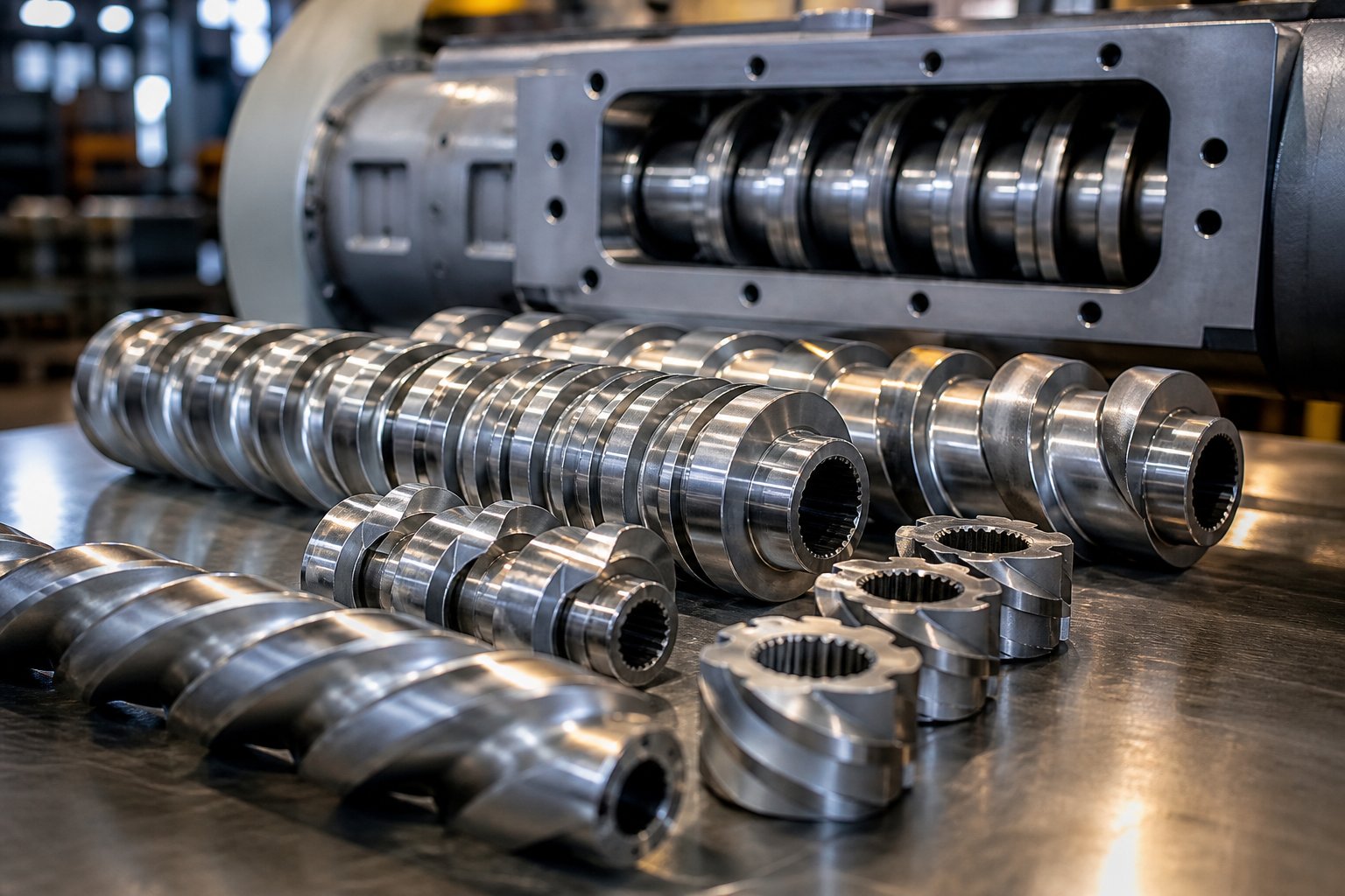
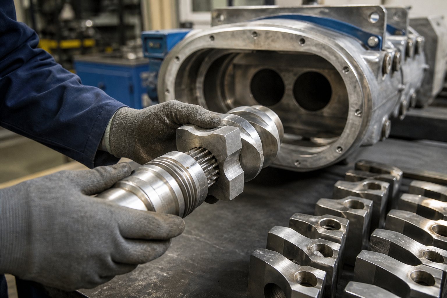
Twin screw elements are modular, interchangeable components that slide onto splined shafts inside co-rotating twin screw extruders. Each element is purpose-built for a specific processing function — conveying, melting, mixing, devolatilizing, or pressurizing material — and engineers can rearrange, swap, and replace individual elements independently to customize screw profiles for any given processing task.
That definition captures the essential idea, but the real significance runs deeper. Unlike a traditional single-screw extruder, where the screw is typically machined as one continuous piece with fixed geometry, a twin screw extruder uses a segmented design. Dozens of individual elements are stacked along each shaft, locked in place by the spline connection, and held together by a tip bolt. You can pull the screws from the barrel, slide off specific segments, and rebuild an entirely different screw profile in hours — sometimes minutes.
Defining Twin Screw Elements and Their Role in Extrusion
So what does a screw actually do inside an extruder? It performs five critical jobs: conveying raw material forward from the feed throat, melting solid polymer through a combination of shear energy and barrel heat, mixing additives or fillers into the melt, removing trapped volatiles and moisture under vacuum, and building enough pressure to push molten material through the die. In a single-screw machine, one fixed geometry has to handle all of these tasks in sequence. In a modular twin screw extruder, each of these functions gets its own dedicated element type — conveying elements, kneading blocks, and specialized mixing elements — each engineered with distinct flight geometry, pitch, and channel depth to excel at one particular job.
This is precisely why co-rotating twin screw extruders dominate applications like plastics compounding, masterbatch production, and polymer recycling. When you're processing a glass-fiber-filled nylon compound on Monday and switching to a carbon black masterbatch on Wednesday, you need the ability to reconfigure your screw profile without buying a new screw. Modular screw elements for a twin screw extruder make that flexibility a practical reality.
Why Modular Element Design Changed Polymer Processing
Before modularity became standard, changing a screw's processing characteristics meant ordering a completely new screw — an expensive, time-consuming commitment. The modular concept changed the economics entirely. Process engineers gained the freedom to experiment: adding a kneading block here to improve dispersion, swapping in a larger-pitch conveying element there to reduce fill level near a vent port, or inserting a reverse element to create a melt seal exactly where it's needed.
This iterative, hands-on approach to screw profile optimization is what separates experienced extruder operators from those who struggle with inconsistent output quality. Yet the knowledge needed to make smart element choices — element taxonomy, geometry fundamentals, profile design logic, wear patterns, and troubleshooting strategies — is typically scattered across dozens of technical papers, supplier catalogs, and tribal knowledge passed between engineers on the plant floor.
The sections ahead bring all of that information into one unified reference. You'll find detailed comparisons of every major element type, clear explanations of the geometric parameters that govern performance, a step-by-step screw profile design workflow, and practical guidance on wear indicators and material selection. Whether you're specifying elements for a new extruder or diagnosing underperformance on an existing line, the foundation starts with a closer look at the engineering geometry that makes twin screw modularity possible in the first place.
How Twin Screw Elements Differ from Single Screw Designs
The modular flexibility described above raises an obvious question: why can't single screw extruders use the same interchangeable element approach? The answer lies in a fundamental difference in screw geometry — one that dictates how material moves, how channels self-clean, and ultimately, whether standardized segments are even feasible.
The Intermeshing Self-Wiping Geometry Explained
Co-rotating twin screw extruders rely on a profile concept patented by Rudolf Erdmenger in 1957 — and it remains the foundation of every modern co-rotating machine. The core principle is elegant: the cross-sectional shape of one screw is the mathematical conjugate of the other. Picture two identical lobed profiles rotating in the same direction, positioned so that the flight tip of one screw continuously sweeps the channel root of its neighbor. This creates a self-wiping action where virtually no material can stagnate on a screw surface, because the adjacent screw constantly scrapes it away.
Why does this matter for processing? Stagnant material in an extruder degrades. It chars, cross-links, or decomposes — then breaks free as contamination in your product. The Erdmenger self-wiping screw profile eliminates dead zones by design. Every rotation pushes material from one screw channel into the intermeshing zone and transfers it to the opposing screw. As Jim Frankland of Plastics Technology explains, the twin screw can "essentially transfer the entire channel full of polymer from one screw to the other multiple times, permitting full-channel mixing" — something a single screw physically cannot replicate.
This screw-to-screw material transfer is also what enables twin screws to apply high shear in small, controlled increments. Material passes through the tight intermeshing gap, experiences intense shear for a brief moment, then relaxes in the open channel volume of the opposite screw. The cycle repeats at every intermeshing point along the barrel length. The result is thorough dispersive mixing without the excessive melt temperature rise that plagues single screw mixers requiring flow restrictions to achieve comparable shear rates.
Why Modularity Works for Twin Screws but Not Single Screws
Here is the connection that often goes unexplained: the self-wiping geometry is what makes modular element design possible. Because each element's cross-sectional profile is mathematically defined by just two fixed parameters — the centerline distance between the two shafts and the outer screw diameter — every element that conforms to those dimensions will automatically maintain the correct intermeshing relationship with its counterpart on the adjacent shaft. Swap a large-pitch conveying element for a kneading block, and the conjugate geometry still works. The wiping action remains intact. The clearances stay consistent.
Single screw extruders lack this geometric constraint. A single screw operates alone inside a smooth barrel bore, relying on the friction between the polymer and the barrel wall to generate forward drag flow. There is no second screw to define a conjugate profile against, no intermeshing geometry to standardize. The screw's performance depends on the continuous, carefully calculated transition of channel depth, flight pitch, and compression ratio along its entire length. Cutting that optimized geometry into interchangeable segments would break the graduated compression profile that a single screw needs to function properly.
The key geometric differences between these two designs can be summarized as follows:
- Number of flights: Co-rotating twin screw elements typically feature two flights (bilobal profile), though trilobal designs exist for specific applications. Single screws almost always use a single flight, occasionally two or three in barrier or mixing sections.
- Self-wiping capability: Twin screws achieve continuous self-cleaning through the conjugate intermeshing profile. Single screws have no inherent self-wiping mechanism — material can accumulate in channel dead spots, particularly in deep-channel feed zones.
- Free volume characteristics: The open cross-sectional area available for material inside the screw channel — known as free volume — is a critical design parameter in twin screws. It directly controls the fill level at a given throughput, dictates how much melt surface area is exposed during devolatilization, and determines pressure generation capacity. Twin screws typically run starved (partially filled), giving engineers precise control over fill level by adjusting feed rate independently of screw speed. Single screws run fully filled in the metering zone, offering far less flexibility.
- Residence time distribution: The intermeshing region in twin screws acts as a series of flow dividers, narrowing the residence time distribution and ensuring that nearly all material experiences similar processing history. Single screws exhibit broader residence time distributions because material near the barrel wall moves faster than material near the screw root, and no screw-to-screw transfer exists to homogenize the flow.
That final point — residence time distribution — has profound practical consequences. A narrow distribution means consistent product quality pellet to pellet. A broad distribution means some material is over-processed while other material is under-mixed, a root cause of many quality complaints in single screw compounding attempts.
The free volume concept deserves special attention because it connects element geometry directly to process control. When you select a large-pitch conveying element, you're creating a channel with high free volume — material moves quickly, fill level stays low, and exposed surface area is maximized. That's ideal beneath a vacuum vent port where you want volatile gases to escape from thin films of melt. Switch to a small-pitch element, and the free volume per unit length drops. The channel fills more completely, pressure builds, and the element becomes effective at pushing melt through a die or creating a melt seal upstream of a vent zone.
Every decision about element selection — pitch, disc width, stagger angle, flight geometry — ultimately comes back to manipulating these fundamental characteristics that the co-rotating twin screw intermeshing profile makes possible. The real question for process engineers is not whether twin screws outperform singles for compounding tasks, but which specific element types to deploy for each processing zone and material challenge.
Types of Twin Screw Extruder Elements Compared Side by Side
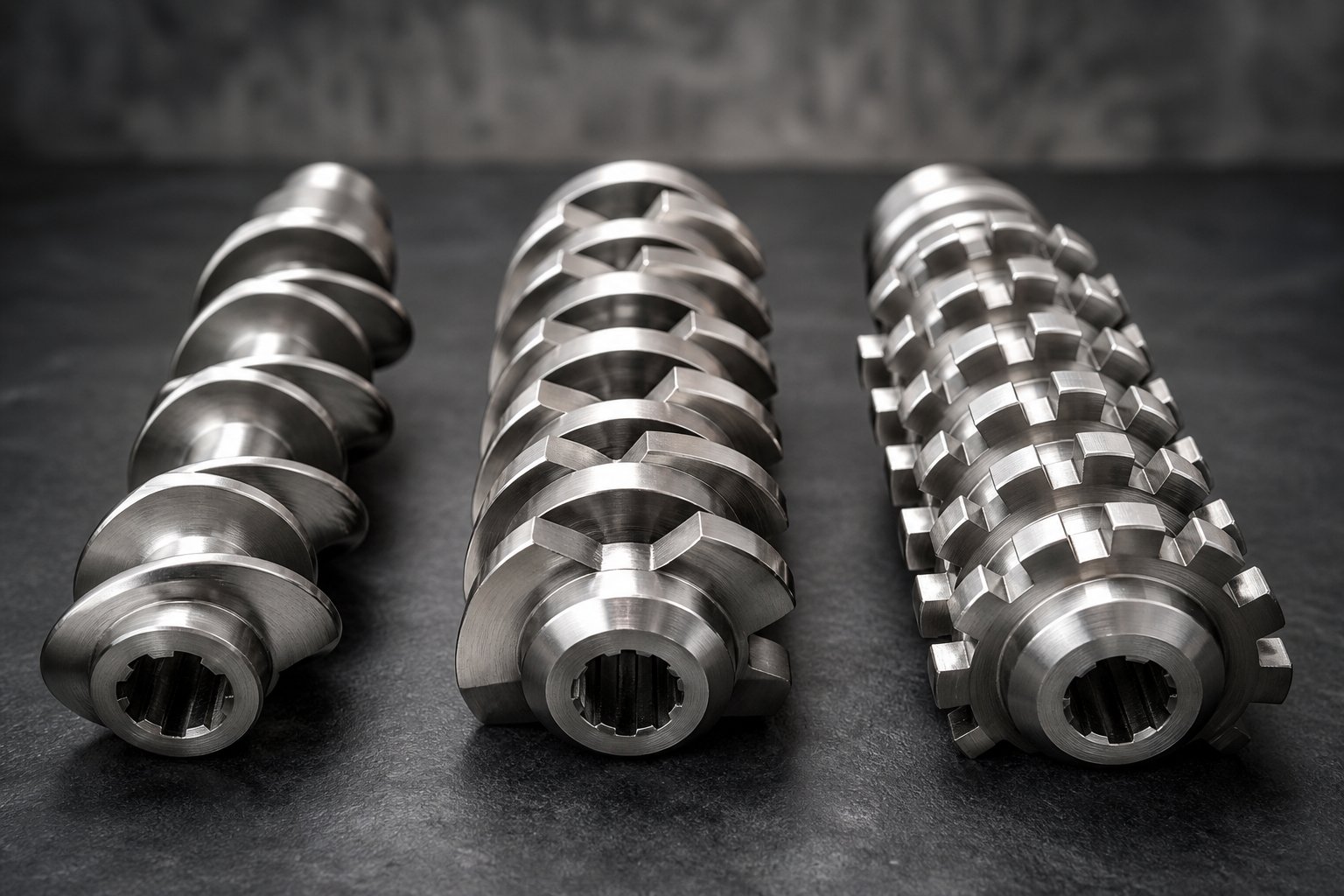
Knowing that the intermeshing geometry enables modularity is only half the picture. The real power of a co-rotating twin screw extruder emerges when you understand the three distinct families of elements available — and more importantly, when you know exactly which family to reach for in each processing zone. Every element on a splined shaft falls into one of three categories: conveying elements, kneading discs (kneading blocks), or specialized mixing elements. Each one manipulates the melt in a fundamentally different way, and selecting the wrong type — or placing the right type in the wrong zone — is one of the most common causes of underperformance.
Before diving into each category individually, consider a direct comparison across the parameters that matter most on the plant floor:
| Parameter | Conveying Elements | Kneading Discs (Kneading Blocks) | Specialized Mixing Elements |
|---|---|---|---|
| Geometry | Continuous helical flights with defined pitch and channel depth; classic Erdmenger self-wiping profile | Stack of individual disc-shaped lobes offset by a stagger angle; no continuous helical flight | Toothed, grooved, or slotted profiles that break conventional flight geometry; often non-self-wiping |
| Primary Function | Material transport, solids intake, pressure generation, and devolatilization support | Dispersive mixing — breaking agglomerates, melting solids, and imposing high shear stress on melt | Distributive mixing — splitting, recombining, and spatially redistributing melt streams at lower shear |
| Typical Placement | Feed zone, transitions between functional zones, vent zones, and discharge/metering zone | Plasticizing (melting) zone and intensive mixing zones where filler dispersion or polymer blending is required | Downstream mixing zones after melting, particularly where gentle homogenization or color distribution is needed |
| Conveying Behavior | Forward (standard) or reverse (left-handed); strong positive displacement pumping action | Forward, neutral, or reverse depending on stagger angle and disc offset direction | Typically mild forward conveying; some designs are conveying-neutral |
| Shear Intensity | Low to moderate — shear occurs mainly at flight tips and barrel wall | Moderate to very high — shear concentrates at disc tips, disc faces, and the intermeshing zone between screws | Low to moderate — designed to maximize flow splitting rather than peak stress |
| Impact on Material | Minimal thermal or mechanical degradation; controls fill level and residence time distribution | Significant energy input; can raise melt temperature and torque rapidly; essential for deagglomeration but risks degradation if overused | Gentle redistribution with minimal temperature rise; ideal for heat-sensitive formulations and fiber preservation |
This side-by-side view reveals a key insight: no single element type can do everything well. Conveying elements move material but barely mix it. Kneading blocks mix aggressively but generate heat and can degrade sensitive polymers. Specialized mixing elements distribute uniformly but lack the shear intensity to break stubborn agglomerates. Building an effective screw profile means combining all three families in the right sequence and proportion.
Conveying Elements and Their Pitch Variations
Conveying elements are the workhorses of any twin screw profile — they appear in almost every zone, and they typically account for the largest portion of the total screw length. Their geometry looks like a traditional helical screw flight: a continuous, self-wiping Erdmenger profile with a defined pitch and channel depth. Simple in concept, yet pitch selection has an outsized influence on everything from throughput to devolatilization efficiency.
Pitch is the axial distance the flight travels in one complete revolution. When you increase pitch, each revolution moves more material forward, the channel stays partially filled at a given feed rate, and residence time in that section drops. When you decrease pitch, conveying capacity falls, the channel fills more completely, and local pressure increases. That single variable — pitch — lets process engineers tune a conveying element for dramatically different jobs:
- Large-pitch elements (e.g., 1.5D to 2D pitch): Used in the feed zone to quickly accept pellets or powder from the hopper and move them downstream without compaction. The high free volume prevents bridging and ensures smooth intake, especially for low-bulk-density materials. Also positioned beneath vacuum vent ports to create partially filled channels that expose maximum melt surface area for volatile removal.
- Medium-pitch elements (e.g., 1D pitch): General-purpose transport between processing zones. They maintain a moderate fill level and provide smooth transitions between aggressive mixing sections.
- Small-pitch elements (e.g., 0.5D to 0.75D pitch): Placed in the metering or discharge zone to build pressure against the die. The reduced free volume forces the channel toward full fill, generating the pressure needed to push melt through downstream tooling such as strand dies, underwater pelletizers, or sheet dies.
- Reverse-pitch (left-handed) conveying elements: These push material backward against the overall flow direction, creating a restrictive seal. They increase fill level and pressure upstream and are often placed ahead of vent ports to establish a melt seal that prevents gas from escaping upstream instead of through the vent.
While conveying elements do generate some shear — particularly in the narrow gap between the flight tip and barrel wall — they are not designed for intensive mixing. CFD simulation research from Paderborn University confirms that conveying elements produce significantly lower distributive mixing quality compared to kneading blocks or toothed mixing elements, with mixing index (MQ) values roughly double those of dedicated mixing geometries under identical conditions. Their contribution to any screw profile is primarily about controlled material transport, fill management, and pressure development — all prerequisites for making the actual mixing elements perform effectively.
Kneading Discs and Their Dispersive Mixing Role
If conveying elements are the workhorses, kneading discs are the heavy lifters. A kneading block consists of multiple individual disc-shaped lobes stacked along the shaft, each rotated by a defined stagger angle relative to its neighbor. There are no continuous helical flights — instead, the offset disc geometry forces melt through a repeating sequence of compression, shear, and expansion as it passes each disc tip and the intermeshing zone between the two screws.
Three design parameters define a kneading block's behavior:
- Disc width: Wider discs create longer shear zones per disc, intensifying dispersive action on each pass. Narrower discs produce more frequent flow interruptions per unit length, generating more interfaces where melt accelerates and decelerates, which enhances both dispersive and distributive mixing. As a general rule, wider discs favor high-shear dispersion while narrower discs deliver a better balance of distribution and dispersion.
- Stagger angle (offset angle): The angular offset between adjacent discs controls whether the block conveys material forward, holds it in place, or pushes it backward. Low stagger angles (30-45 degrees) produce forward-conveying blocks with moderate mixing. A 90-degree offset creates neutral blocks with zero net conveying — material oscillates across the discs, drastically increasing residence time and shear exposure. Reverse stagger angles create backward-pumping blocks used for melt seals and maximum dispersive intensity.
- Number of discs per block: More discs in a single block extend the mixing zone length, increasing the total number of shearing passes and overall energy input. Fewer discs create shorter, more targeted mixing events with less cumulative temperature rise.
The twin screw kneading block function is primarily dispersive: breaking up agglomerates of pigment, filler particles, or immiscible polymer phases by imposing shear stresses that exceed the cohesive strength holding those clusters together. This is why kneading blocks dominate the plasticizing zone (where they help complete melting through intense mechanical energy input) and the primary mixing zone (where they deagglomerate fillers and disperse additives).
However, kneading blocks come with a trade-off. Every increment of mixing intensity translates to additional viscous heating and higher torque demand on the motor. Overloading a profile with aggressive kneading blocks — too many discs, too steep a stagger angle — is one of the most common configuration mistakes, leading to excessive melt temperatures, polymer degradation, and energy waste. The key is applying kneading blocks surgically: just enough dispersive action to achieve the required particle size reduction, and no more.
Specialized Mixing and Distributive Elements
When the goal shifts from breaking things apart to spreading them evenly, specialized distributive mixing elements for the twin screw extruder take over. These elements use geometries that deliberately depart from the classic self-wiping Erdmenger profile. Instead of continuous flights or stacked discs, they feature teeth, slots, grooves, or interrupted channels designed to repeatedly split and recombine the melt stream — achieving excellent spatial uniformity without imposing the peak shear stresses that kneading blocks generate.
The most common sub-variants include:
- Toothed mixing elements (ZME / TME): These elements feature rows of interlocking teeth rather than continuous flights. Material is forced through narrow passages between teeth, divided into many small streams, and recombined downstream. Research from Paderborn University found that toothed mixing elements achieved the best distributive mixing quality among five tested element types — outperforming even full-length 90-degree kneading blocks — while simultaneously generating high maximum shear stresses on individual particles. This dual capability makes them exceptionally versatile.
- Screw mixing elements (SME): Sometimes called "comb" or "slotted" elements, these start with a standard conveying profile but add slots or cuts through the flights. These interruptions allow material to flow both over and through the flight, dramatically increasing the number of flow splits per revolution. SMEs are popular for color homogenization and additive distribution where gentle handling is essential.
- Blister rings and restriction elements: While not mixing elements in the traditional sense, these disc-like restrictions create localized high-pressure zones upstream and low-pressure zones downstream. They are commonly placed ahead of vent ports to establish a melt seal, ensuring that vacuum is applied to a partially filled zone where volatiles can escape rather than to a fully pressurized melt.
- Turbine-type and gear-type mixing elements: These specialized designs borrow from the geometry of gear pumps or turbine blades. They excel at low-shear distributive mixing for applications like reactive extrusion or blending heat-sensitive bio-based polymers, where even moderate kneading block intensity would cause thermal degradation.
The practical value of this third element family becomes especially clear when you're processing fiber-reinforced compounds. Aggressive kneading blocks will shorten glass or carbon fibers — directly degrading the mechanical properties you're trying to achieve. Distributive mixing elements can uniformly spread those fibers throughout the matrix without excessive breakage, preserving fiber aspect ratio and the compound's structural performance.
Choosing between these three element categories is rarely an either/or decision. Effective screw profiles blend all three in a carefully sequenced arrangement: conveying elements to transport and control fill, kneading blocks to melt and disperse, and specialized mixing elements to homogenize and distribute. The geometry parameters that govern each element's behavior — pitch, stagger angle, disc width, flight clearances — are what ultimately translate design intent into processing reality. Understanding exactly what these parameters mean and how they interact is the next critical piece of the puzzle.
Essential Screw Element Terminology and Geometry Parameters
You have seen how pitch, stagger angle, and disc width appeared repeatedly in the element comparisons above — almost like a shorthand language that experienced engineers use to describe what each component does. But here is the problem: if you cannot define those terms precisely, you cannot read an element specification sheet, predict how a particular geometry will behave, or communicate clearly with a supplier about what you need. Every twin screw element is ultimately defined by a handful of measurable geometric parameters. Master those parameters, and you gain the ability to decode any element designation, anticipate its processing effect, and make confident swaps during profile optimization.
Think of this section as your dictionary. Each term below connects a physical dimension to a processing outcome — and together, they form the vocabulary you need to speak the language of twin screw flight geometry parameters fluently.
Pitch, Lead, and Flight Geometry Parameters
These four parameters describe the helical shape of a conveying element's flight and directly control how quickly — and how forcefully — material moves through any given barrel section.
- Pitch: The axial distance between two consecutive flights measured along the screw axis. Imagine standing at one flight crest and looking downstream to the next crest on the same flight — that gap is the pitch. A large pitch means each revolution sweeps material over a longer axial distance, resulting in fast conveying and low fill. A small pitch compresses more flights into the same barrel length, slowing material down and building pressure. As NC State's extrusion processing reference notes, increasing the pitch of a screw element increases the shear input on the material — a detail that may seem counterintuitive until you consider the higher drag velocity acting over a longer helical path.
- Lead: The axial distance the material advances in one full revolution of the screw. For a single-flighted element, lead equals pitch. For the bilobal (two-flighted) elements typical of co-rotating twin screws, lead equals pitch multiplied by the number of flights. So a two-flighted element with a 20 mm pitch has a 40 mm lead — meaning one complete shaft rotation moves material 40 mm forward. Confusing pitch with lead is one of the most common specification errors, and it can result in ordering elements that convey at half or double the intended rate.
- Channel depth: The radial distance from the screw root (the bottom of the channel) to the tip of the flight. Deeper channels hold more material per unit length, increasing free volume and reducing shear rate in the channel. Shallower channels restrict volume and raise shear. As a rule, channel depth decreases in the order: conveying zone > compression zone > metering zone, reflecting the progressive shift from bulk transport to pressure-building as material moves toward the die.
- Flight thickness (flight width): The width of the flight land — the flat surface at the outermost tip of the flight that rides against the barrel wall with minimal clearance. This land is responsible for the wiping action that keeps the barrel surface clean and prevents material stagnation. Thicker flight lands increase the wiping contact area and provide more structural rigidity, but they reduce the open channel width available for material flow. Thinner flight lands maximize channel volume but wear faster and are more vulnerable to mechanical damage from hard contaminants.
These four parameters are deeply interconnected. Increasing pitch while holding channel depth constant raises the helix angle of the flight, changing the ratio of drag flow to pressure flow in the channel. Increasing channel depth at the same pitch boosts free volume but reduces the element's ability to generate forward pressure. Engineers who understand the screw element pitch and lead definition — and how these dimensions cascade into conveying rate, fill level, and shear — can predict an element's behavior before it ever touches polymer.
Overflight Gap, Tip Angle, and Clearances
If pitch and channel depth define the big picture of a conveying element's performance, clearances define the fine print. The gaps between the element and the barrel wall — and between the two intermeshing screws — are measured in fractions of a millimeter, yet they exert disproportionate control over leakage flow, shear rate, and self-wiping effectiveness.
- Overflight gap (flight clearance): The radial gap between the flight tip and the inner barrel wall. For conventional twin screw extruders, this clearance is typically on the order of 0.001 times the barrel diameter — a few hundredths of a millimeter on small machines, up to roughly 0.1 mm on larger ones. This narrow gap serves two competing roles. First, it allows the flight to wipe the barrel wall, preventing material buildup and ensuring self-cleaning behavior. Second, it creates a thin film through which a small amount of melt leaks backward from the high-pressure side to the low-pressure side of the flight. Research on leakage-flow modeling has demonstrated that the volume of this backflow — and the shear rate imposed on material passing through the gap — are both highly sensitive to the clearance dimension. Even modest increases in overflight gap clearance due to wear can measurably reduce a twin screw's pumping efficiency and alter the shear history of the melt.
- Tip angle: The angular geometry of the flight tip as seen in cross-section. A blunt, flat-topped tip creates a wider wiping surface and a more uniform shear field across the clearance. A sharper, more tapered tip concentrates shear into a narrower band and slightly increases the ratio of drag flow to pressure flow at the barrel wall. Tip angle selection is often a compromise between wear resistance (blunt tips last longer) and processing performance (sharper angles can improve conveying efficiency for certain polymer viscosities). In practice, most standard twin screw elements use a flat or slightly rounded tip geometry optimized for the Erdmenger self-wiping profile.
- Intermeshing clearance: The gap between the flight tip of one screw and the root of the opposing screw in the intermeshing zone. This clearance is closely related to the overflight gap and is defined by the same centerline-distance-to-diameter relationship that governs the entire self-wiping profile. Material passing through this gap experiences the highest shear rates in the entire extruder cross-section — a key mechanism driving dispersive mixing. As this clearance increases through wear, both mixing efficiency and self-wiping performance degrade simultaneously.
Why do tight tolerances matter so much? Because the self-wiping action that defines co-rotating twin screw elements depends on maintaining these micro-scale clearances within their design envelope. When flight tips erode and the overflight gap widens by even 50 percent, three things happen at once: leakage flow increases (reducing net forward pumping), the shear rate in the clearance drops (weakening dispersive mixing), and material begins to accumulate on the barrel wall (compromising the self-cleaning behavior that prevents degradation). This is why monitoring clearance dimensions during scheduled inspections is one of the most cost-effective quality protection measures available.
Stagger Angle in Kneading Blocks
Kneading blocks do not have pitch or lead in the traditional sense — they are not helical. Instead, their behavior is governed by a single angular parameter that is unique to disc-based elements: the stagger angle.
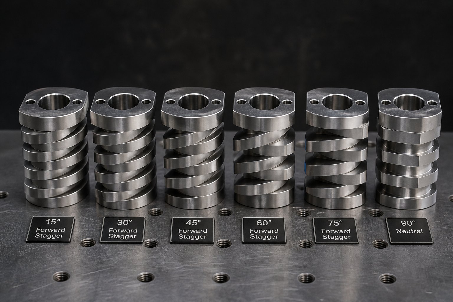
The kneading block stagger angle meaning is straightforward: it is the angular offset between each adjacent disc in the block, measured in the direction of screw rotation. Imagine looking down the shaft at a kneading block's cross-section. The first disc sits at 0 degrees. The second is rotated, say, 45 degrees clockwise. The third is at 90 degrees. That consistent 45-degree step between each disc is the stagger angle.
This single number controls two critical processing variables simultaneously:
- Conveying behavior: A small forward stagger angle (such as 30 degrees) creates a near-helical path that pushes material downstream — the block still conveys, though less efficiently than a true conveying element. As the angle increases toward 90 degrees, the forward-pumping effect weakens until it reaches zero at a neutral (90-degree) configuration. Reverse stagger angles flip the effect entirely, pushing material backward and creating a restriction that raises upstream fill and pressure.
- Mixing intensity: Wider stagger angles force material to traverse more abrupt transitions between disc faces. At each transition, the melt is squeezed through the gap between the disc tip and the barrel wall, subjected to intense shear, then released into the open volume behind the next disc. More transitions per unit length and longer dwell at each transition mean higher cumulative shear exposure. A 90-degree neutral block delivers the most intense mixing because material cannot escape downstream — it circulates across the disc tips repeatedly until forward-conveying elements downstream pull it away.
Understanding pitch, lead, overflight gap, and stagger angle transforms element specification sheets from cryptic part numbers into actionable processing instructions. An engineer who knows that a KB45/5/30R designation describes a 45-degree forward-staggered kneading block with five discs over 30 mm of length can immediately predict its moderate mixing intensity, positive conveying contribution, and suitability for initial melting — without consulting a single catalog illustration.
These geometry parameters do not operate in isolation. The disc width within a kneading block interacts with stagger angle to fine-tune the balance between dispersive and distributive mixing. A wide disc at 60 degrees delivers more shear per disc passage than a narrow disc at the same angle, because the material spends more time under the disc tip before reaching the next flow interruption. Narrow discs, by contrast, multiply the number of flow divisions per unit length, promoting distributive redistribution of the melt. Engineers who pair stagger angle selection with disc width selection can dial in exactly the mixing character their formulation demands.
With this geometric vocabulary in hand, the natural next step is exploring how different stagger angle progressions translate into radically different melting and mixing outcomes — and why the sequence of angles along the shaft often matters more than any individual block's geometry.
Kneading Disc Stagger Angles and Mixing Mechanics
Stagger angle determines whether a kneading block gently nudges material forward, holds it in place for intensive work, or actively forces it backward to create a pressurized seal. Yet many process engineers treat kneading blocks as interchangeable mixing devices, reaching for whatever is closest on the shelf. The result? Either too much shear — degrading the polymer and spiking melt temperature — or too little mixing — leaving agglomerates intact and color streaks visible in the final product. Choosing between a forward vs reverse kneading block configuration is not a matter of preference. It is a processing decision with direct, measurable consequences for product quality, energy consumption, and throughput.
Forward-Conveying Kneading Blocks and Their Processing Effect
When the stagger angle between adjacent discs is relatively shallow — typically 30 or 45 degrees in the direction of screw rotation — the offset creates a quasi-helical path that pushes material downstream while simultaneously shearing it across each disc face. You can think of these blocks as a hybrid: part conveying element, part mixer. The material does not linger. It moves forward with each revolution, passes over disc tips, and experiences moderate dispersive shear along the way.
This combination of transport and mixing makes forward-staggered kneading blocks ideal for two specific jobs:
- Initial melting (plasticizing zone): Solid pellets or powder arriving from the feed zone need mechanical energy input to soften and begin melting. A 30-degree or 45-degree forward kneading block introduces that energy gradually, avoiding the kind of sudden, intense shear that would spike melt temperature beyond the set point. As twin screw configuration principles confirm, forward kneading blocks allow most of the material to undergo controlled and constant shear, keeping the material temperature low compared to more aggressive configurations.
- Gentle distributive premixing: Before additives encounter an intense dispersive zone, a forward-staggered section can pre-blend materials at relatively low shear, ensuring a more uniform feed into the high-intensity mixing zone downstream. This prevents localized overconcentration of fillers or pigments that can lead to hot spots and inconsistent dispersion.
A 30-degree block conveys more aggressively and shears less intensely per revolution than a 45-degree block. The 45-degree variant strikes what many experienced compounders consider the best general-purpose balance — meaningful mixing without excessive residence time. As the stagger angle increases, the forward motion decreases, causing material to back up and enabling more intense work on the polymer per screw revolution.
Neutral and Reverse-Conveying Kneading Block Configurations
Increase the stagger angle to 90 degrees and something dramatic happens: the kneading block stops conveying entirely. A 90 degree neutral kneading block functions as a pure mixing element — it neither pushes material forward nor backward. The discs are offset at right angles to each other, so there is no helical progression. Material sits in the block, tumbling across disc tips and through intermeshing gaps, until forward-conveying elements or upstream pressure push it downstream.
Why would you deliberately stall material flow? Because residence time in the mixing zone increases dramatically, and every additional millisecond of exposure to the high-shear intermeshing region drives more thorough dispersive mixing. Stubborn agglomerates — tightly bound carbon black clusters, mineral filler aggregates, or poorly wetted pigment particles — need that extended shear history to break apart. A neutral block delivers it without the mechanical violence of a reverse element.
Reverse-staggered kneading blocks take things further. At stagger angles of -30 or -45 degrees (offset against the direction of conveying), the block actively pumps material backward. This creates a pressurized dam in the barrel, forcing the upstream zone to fill completely. The practical effects are twofold: extremely high local shear stress on every particle passing through the block, and the formation of a melt seal that prevents gas or volatile compounds from migrating upstream. Reverse kneading blocks are essential tools for demanding dispersive tasks like deagglomerating tightly bound pigment particles in masterbatch production, and they are frequently positioned just upstream of vacuum vent ports to seal the melt before the low-pressure devolatilization zone.
However, reverse elements come with a cost. The kneading disc stagger angle effect on mixing is never free — backward pumping generates significant viscous heating and imposes heavy torque loads on the drive system. Overuse of reverse blocks is one of the fastest routes to polymer degradation, excessive melt temperature, and premature equipment wear. Experienced screw designers typically limit reverse kneading blocks to the specific locations where nothing else can deliver the required mixing intensity or melt seal.
The following table maps each stagger angle range to its processing behavior, providing a quick-reference framework for element selection:
| Stagger Angle | Conveying Behavior | Mixing Type | Relative Shear Intensity | Typical Application |
|---|---|---|---|---|
| 30° (forward) | Strong forward conveying | Mild dispersive + distributive | Low | Initial melting, gentle premixing, transitional zones |
| 45° (forward) | Moderate forward conveying | Balanced dispersive + distributive | Moderate | General-purpose plasticizing and mixing; most common starting point for screw design |
| 60° (forward) | Weak forward conveying | Primarily dispersive | Moderate-High | Filler deagglomeration in compounds with moderate shear sensitivity |
| 90° (neutral) | Zero net conveying | Intensive dispersive | High | Demanding pigment dispersion, breaking stubborn agglomerates, completing melting of high-viscosity polymers |
| -30° to -45° (reverse) | Backward pumping | Maximum dispersive | Very High | Melt seal creation before vent ports, extreme dispersion for carbon black or nano-fillers, reactive extrusion barrier zones |
How Disc Width Modifies Mixing Behavior
Stagger angle tells you how aggressively a kneading block works the material — but disc width determines how it works. Imagine two kneading blocks, both set at a 45-degree stagger, both occupying the same 60 mm of barrel length. One uses 5 wide discs (12 mm each), the other uses 10 narrow discs (6 mm each). The stagger angle is identical. The mixing character is not.
Wide discs create a broad, sustained shear zone. As each disc rotates, it plows through the melt pool accumulated in front of it, smearing and compressing material against the barrel wall over the full width of the disc face. The shear forces here are quite high, making wide discs the go-to choice when dispersive action is the priority — for example, when you need to rupture cohesive agglomerates of carbon black aggregates that resist gentle mixing.
Narrow discs work differently. Instead of plowing, they slice. Each thin disc cuts through the melt in a scissoring action, dividing the material stream at every disc transition. With more discs packed into the same axial length, the melt experiences more divisions and recombinations per unit length. This repeated splitting and layering is the essence of distributive mixing — spatially rearranging material to achieve uniformity without necessarily imposing peak shear stress. Narrow disc kneading blocks are the preferred configuration when you want to distribute color concentrate evenly through a polymer matrix, or when you need to blend additives into a heat-sensitive resin that cannot tolerate the temperature rise from wide-disc dispersive action.
The relationship between kneading disc width and shear intensity can be summarized simply: wider discs mean fewer, more powerful shear events per block length; narrower discs mean more frequent, gentler flow interruptions per block length. When paired with stagger angle selection, disc width gives engineers a second axis of control. A wide-disc block at 90 degrees delivers the most aggressive dispersive mixing available in a standard twin screw element toolkit. A narrow-disc block at 30 degrees delivers gentle distributive blending with strong forward conveying. Every combination in between allows precise calibration of mixing character to match the formulation's requirements.
This level of control over mixing mechanics is precisely what makes modular screw design so powerful — and why getting the sequence wrong can be so costly. The stagger angle progression along the barrel, combined with the disc width at each stage, dictates whether material melts smoothly or overheats, whether fillers disperse uniformly or survive as visible specks, and whether the polymer exits the die with the target properties or arrives degraded. Translating these element-level decisions into a complete, zone-by-zone screw profile is where theory meets the demands of real-world production.
Step-by-Step Screw Profile Design from Feed to Discharge
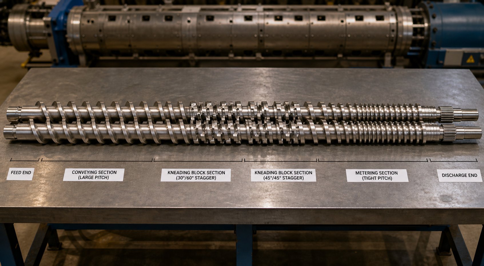
Selecting the right stagger angle and disc width for a single kneading block is one thing. Arranging dozens of individual elements across the full barrel length — so that every zone transitions smoothly into the next, every function happens at the right location, and no single section creates a bottleneck — is an entirely different challenge. This is the twin screw extruder screw profile design guide that brings element-level knowledge together into a complete, actionable workflow.
Designing a screw profile is, as NC State's extrusion processing reference puts it, "a blend of art and science." No universal gold standard exists because every material exhibits unique flow properties influenced by temperature, shear rate, and extruder geometry. But that does not mean the process is guesswork. A disciplined, zone-by-zone approach — anchored in your formulation's requirements — turns screw profile design from tribal knowledge into a repeatable engineering method.
Before touching a single element, work through this decision checklist to define the constraints that will drive every downstream choice:
- Identify the base polymer and its rheology — Is it shear-thinning? Heat-sensitive? What is its melting point or glass transition temperature? High-viscosity resins demand more mechanical energy input for melting and generate more viscous heat, which limits how aggressive your kneading blocks can be.
- Determine additives and filler loading — Are you incorporating 5% color concentrate or 60% calcium carbonate? High filler loadings require more intensive dispersive mixing and wear-resistant element materials. Low loadings may need only distributive blending.
- Set target throughput — Throughput determines how quickly material moves through each zone. Higher rates demand larger-pitch feed zone elements to prevent starving, and more aggressive pressure-building elements near the die to compensate for increased flow resistance.
- Define mixing intensity requirements — Does the formulation need gentle distributive blending (color masterbatch into a carrier resin) or aggressive dispersive deagglomeration (nano-fillers, tightly bound pigment clusters)?
- Identify thermal constraints — What is the maximum allowable melt temperature before the polymer degrades, discolors, or cross-links? This ceiling directly limits the total energy input from kneading blocks and reverse elements.
- Map zones to element types — With the above answers in hand, assign specific element families and geometries to each barrel section, working from feed throat to die face.
That final step — mapping zones — is where the real design work happens. Every twin screw barrel can be divided into three to five functional zones, each with distinct element requirements. Here is how to select screw elements for each zone, starting where the material first enters the machine.
Feed Zone and Solids Conveying Element Selection
The feed zone has one job: accept raw material from the feeder and move it downstream as quickly and smoothly as possible. Sounds simple, but poor feed zone conveying element pitch selection is responsible for a surprising number of throughput limitations and processing instabilities.
Large-pitch conveying elements — typically in the range of 1.5D to 2D pitch (where D is the screw diameter) — are the standard choice here. Their deep channels and high free volume create an open pathway that prevents incoming pellets, granules, or powder from compacting against one another and bridging across the screw channel. This is especially critical for low-bulk-density materials like recycled flake, fluffy powders, or pre-expanded beads, where even moderate compaction can choke the feed throat and cause surging.
The relationship between the extruder's feed barrel configuration and initial element choices matters more than many engineers realize. Open-barrel feed sections (with a large port cut into the top of the barrel) expose material to the screw over a wide arc, maximizing intake. But that benefit disappears if the elements beneath the port have too small a pitch — the reduced channel volume cannot accept material as fast as gravity and the feeder deliver it. Conversely, using excessively large-pitch elements beyond the feed port wastes barrel length on high-speed transport that could be better used for melting or mixing.
A practical starting point: use your largest available pitch element directly beneath the feed opening, then step down to a medium pitch (around 1D) for one to two barrel sections downstream. This gradual transition compresses material gently, increasing interparticle contact and preparing it for the energy-intensive melting zone ahead — without creating an abrupt restriction that could cause upstream backup.
Melting, Mixing, and Devolatilization Zone Configuration
Once material passes the feed zone, the screw profile's character shifts from transport to transformation. Three distinct functional zones typically occupy the middle and downstream sections of the barrel, and each one requires a carefully matched combination of element types.
The plasticizing (melting) zone is where solid polymer first encounters enough mechanical and thermal energy to transition into a melt. This zone usually begins with forward-staggered kneading blocks — 30- or 45-degree offsets that introduce shear progressively while still conveying material downstream. The goal is to complete melting without overshooting the target melt temperature. For shear-sensitive polymers like PVC or certain bioplastics, this zone may use narrow-disc forward kneading blocks exclusively. For tough-to-melt crystalline polymers like HDPE or POM, wider discs at 60-degree stagger may be necessary to supply enough mechanical energy for rapid melting.
A short section of conveying elements typically follows the initial melting kneading blocks, providing a brief relaxation zone where the melt can cool slightly through barrel heat exchange before entering the next intensive section.
The mixing zone is where additives, fillers, and pigments are incorporated and dispersed. Element selection here depends entirely on the mixing intensity requirements identified in the checklist above. Demanding dispersive tasks — deagglomerating tightly bound carbon black or breaking up mineral filler clusters — call for 60- or 90-degree kneading blocks, potentially with wide discs. Gentler distributive tasks — spreading color concentrate or blending compatible polymer phases — favor narrow-disc kneading blocks or toothed mixing elements that achieve spatial uniformity without peak shear stress. Many profiles use a sequence of progressively more aggressive kneading blocks (30, then 45, then 60 or 90 degrees) to ramp up intensity gradually, minimizing the thermal shock that can occur when cold, unmelted material hits a high-shear element abruptly.
The devolatilization zone is one of the most misunderstood sections of any screw profile, yet the principles are straightforward. Its purpose is to expose as much melt surface area as possible to a low-pressure environment — typically under vacuum — so that trapped moisture, residual monomers, or dissolved gases can escape. As devolatilization expert Rob Jerman explains in Plastics Technology, a typical devolatilization zone consists of a partially filled screw section isolated between two filled, sealed regions. The upstream seal is created by a neutral or reverse element that forces the screw to be completely full, preventing air from passing from the rear of the extruder into the devolatilization zone. The downstream seal works similarly — often the die itself serves this function.
The devolatilization zone screw element configuration follows a specific logic: place a restrictive element (reverse conveying or reverse kneading block) upstream of the vent port to create the melt seal, then immediately transition to large-pitch conveying elements beneath the vent opening. These high-free-volume elements ensure the channel runs only partially filled, spreading the melt into thin films that maximize the surface-area-to-volume ratio. The thinner the film, the shorter the diffusion path for volatile molecules to reach the melt surface and escape into the vacuum. A useful rule of thumb is that each properly designed vent can reduce volatile concentration by roughly an order of magnitude — a triple-vented machine can bring a 50%-solids feed down to less than 0.1% residuals.
One critical design caution: the downstream seal of a devolatilization zone must not be too restrictive or too close to the vent port. If throughput is too high, screw speed too low, or the restriction too tight, the filled melt section can back up beneath the vent opening and flood into the vent — eventually blocking the vacuum line and shutting down the process.
Pressure-Building Discharge Zone Design
Everything upstream — feeding, melting, mixing, devolatilizing — is wasted effort if the screw profile cannot build enough pressure to push melt through the die at a stable, uniform rate. The discharge zone is where that pressure develops, and the element selection here is governed by a simple principle: progressively reduce pitch to progressively increase fill level and pressure.
A typical discharge zone starts with medium-pitch conveying elements (around 1D) that transition into small-pitch elements (0.5D to 0.75D) approaching the die. This gradual reduction in free volume forces the melt to fill the channels completely, generating the hydraulic pressure needed to overcome the resistance of the die, screen pack, and any downstream tooling like pelletizers or sheet dies. The final element before the die tip is often the smallest pitch available for the extruder size.
The balance here is delicate. Use elements with too small a pitch too early, and you over-pressurize the melt, generating unnecessary viscous heating and increasing torque demand on the motor. Use elements with too large a pitch near the die, and the screw never builds enough pressure — leading to surging output, inconsistent strand diameter, or die drool. The optimal progression depends on the die's pressure-drop characteristics and the target throughput. Higher throughput rates require more pressure-building length. Higher-viscosity polymers generate more pressure per unit length but also more heat, which may necessitate compromising on throughput to stay within the thermal window.
Taken together, these zone-by-zone decisions form a complete screw profile that reads like a processing story from left to right: accept material, melt it, mix in the additives, remove the volatiles, and pressurize the melt for shaping. Every element choice along that path reflects a trade-off between conveying efficiency, mixing intensity, thermal energy input, and pressure development. The profile is never truly "finished" — it evolves as formulations change, throughput targets shift, or wear gradually alters element clearances and performance. Recognizing how elements degrade over time — and knowing which material of construction to specify for each processing challenge — is essential for keeping a well-designed profile performing as intended over months and years of production.
Element Material Selection and Wear Pattern Indicators
A screw profile that runs flawlessly in week one will not deliver the same performance six months later. Every revolution grinds polymer, filler particles, and reinforcing fibers against flight tips, disc faces, and channel walls — gradually eroding the precise clearances that make self-wiping geometry work. Twin screw element wear patterns and indicators are not random. They follow predictable paths determined by element type, compound abrasiveness, and operating conditions. Recognizing those patterns early — and choosing the right element material from the start — is the difference between planned maintenance and an emergency shutdown.
How Different Element Types Wear Over Time
Not all elements degrade the same way. Each geometry concentrates contact forces in different locations, producing distinct wear signatures that experienced engineers learn to read like a diagnostic map.
Conveying elements bear the brunt of abrasive wear on their flight tips — the narrow land that rides against the barrel wall with sub-millimeter clearance. The leading edge of each flight, where incoming material first strikes the rotating surface, also erodes progressively. Over time, the sharp machined corners of screw flights appear rounded, smooth, and occasionally polished — a telltale sign of abrasive erosion. As flight tips flatten, the overflight gap widens, leakage flow increases, and net forward pumping efficiency drops. You'll notice throughput declining before you ever pull the screws for inspection.
Kneading discs experience a double assault. Their tip surfaces wear against the barrel wall just like conveying flights, but the disc faces — the flat surfaces where melt is sheared and compressed between adjacent discs — also erode from the constant high-shear interaction with abrasive particles. This dual-surface degradation is why kneading blocks in mineral-filled compound lines often need replacement before the conveying elements on the same shaft.
Specialized mixing elements, particularly toothed designs with narrow tooth features and thin wall sections, are the most vulnerable to erosion. Their fine geometries offer less material volume to sacrifice before the tooth profile degrades to the point where flow-splitting capability is lost. A toothed mixing element that has lost its sharp tooth edges delivers distributive mixing only marginally better than a worn conveying element.
Regardless of element type, wear manifests through the same downstream consequences: increased overflight gap, loss of self-wiping capability, reduced conveying efficiency, and degraded mixing performance. The insidious part is that these effects compound — as clearances open, more material leaks backward, fill levels change, residence time distribution broadens, and product consistency suffers in ways that are difficult to attribute without physical inspection.
Material Selection Based on Processing Demands
The question of when to replace twin screw extruder elements is closely tied to what those elements are made of. Choosing the right base material and surface treatment for your specific compound delays that replacement date significantly — sometimes by years.
Screw element material selection for abrasive compounds follows a clear hierarchy driven by formulation severity:
- Nitrided steel (e.g., 38CrMoAlA): The workhorse for general-purpose compounding. Gas nitriding produces a hard surface layer (typically 500-570°C treatment temperature) that resists moderate abrasion at a reasonable cost. Suitable for unfilled polymers, lightly filled compounds, and color concentrates without hard pigments. When your formulation contains fewer than 20% non-abrasive fillers, nitrided steel delivers an excellent balance of cost, machinability, and wear resistance.
- Powder metallurgy tool steels (PM-HIP): Manufactured through hot isostatic pressing of pre-alloyed powders, these steels achieve a uniform microstructure with evenly distributed hard carbide particles throughout the matrix — not just on the surface. This makes them dramatically more durable than nitrided steel when processing glass-fiber-filled engineering plastics, where short, stiff fibers act like microscopic cutting tools against every surface they contact. PM-HIP elements can last three to five times longer than nitrided alternatives in 30-40% glass-fiber-reinforced nylon or polyester compounds.
- High-wear-resistance HIP alloy steels (e.g., WR5, WR13, CPM series): These premium materials incorporate ultra-high levels of strong carbide-forming elements like vanadium and tungsten, producing extremely high wear resistance that far exceeds ordinary high-speed steel. They are specified for the most punishing applications: highly filled mineral compounds at 60%+ loading, aggressive flame retardant packages, or continuous processing of recycled streams containing metallic contaminants.
- Nickel-based alloys: Corrosive processing environments — fluoropolymers like PVDF and PTFE, halogenated flame retardants, or reactive extrusion with acidic byproducts — attack steel elements chemically rather than mechanically. Nickel-based alloys form a stable passivation layer that resists this chemical attack, protecting the element even when the pH of decomposition products drops to levels that would pit or dissolve standard steel.
- Tungsten carbide coatings (HVOF sprayed): When the base material alone cannot survive the abrasive environment, high-velocity oxygen fuel (HVOF) spraying deposits a dense tungsten carbide layer onto element surfaces. The tungsten carbide coated screw elements benefits are substantial: surface hardness exceeding 1200 HV, exceptional resistance to abrasion from glass fibers, CaCO3, and carbon black, and the ability to extend service life by multiples in applications that would consume even PM-HIP elements within months. The coating bonds metallurgically to the substrate, resisting the peeling and delamination issues that have limited older hard chrome plating approaches.
The key insight here is that material selection is not a cost decision made in isolation — it is an operating economics calculation. Spending three times more on PM-HIP elements that last five times longer reduces both replacement part costs and production downtime for screw pulls. The most expensive element is the cheap one that fails mid-run.
Beyond material choice, recognizing the visual and measurable indicators that signal replacement is critical for preventing quality problems before they reach your customers:
- Visible scoring on flight lands: Deep grooves running circumferentially around flight tips indicate adhesive wear from metal-to-metal contact — often caused by insufficient screw support within the barrel or contamination with hard foreign particles.
- Measurable increase in tip clearance: A practical guideline is that elements should be replaced when the outer diameter has worn by approximately 5% off the starting diameter over three-quarters of the element length. Beyond this threshold, self-wiping performance degrades significantly.
- Declining product quality: Unmixed gels, visible filler agglomerates, color streaks, or increasing levels of black specks (from degraded material accumulating in widened clearances) are downstream symptoms of upstream wear.
- Increased specific energy consumption: As elements wear, the extruder motor must work harder to achieve the same throughput and mixing result. Tracking kilowatt-hours per kilogram of output over time creates a trend line that flags gradual wear before physical inspection confirms it.
Inspection and Replacement Best Practices
Pulling screws for inspection is not a casual task, but treating it as routine maintenance — rather than an emergency response to quality complaints — pays for itself many times over.
The physical process begins with heating the barrel to operating temperature (or slightly above) to soften residual polymer, then retracting the screw shafts from the barrel bore. Once extracted, individual elements slide off the splined shafts in sequence. Each element should be cleaned, labeled with its position on the shaft, and measured with calibrated tools — a micrometer for outer diameter readings at multiple points along the element length, and feeler gauges for checking the remaining clearance between disc faces in kneading blocks.
Document every measurement. A simple spreadsheet tracking element position, original OD, current OD, and date of measurement creates a wear history that reveals which barrel zones degrade fastest — information that directly informs future material selection decisions. Zones that consistently consume elements faster than others may benefit from upgrading to a harder material grade in those specific positions, rather than upgrading the entire screw set at significantly higher cost.
Establish a regular inspection interval based on your compound's abrasiveness. For unfilled or lightly filled polymers on nitrided steel elements, annual inspections may suffice. For highly filled or glass-fiber-reinforced compounds, quarterly or even monthly checks are warranted — especially during the first production campaign on a new formulation, when wear rates are still unknown. As industry best practice recommends, checking inside the extruder barrel on a regular basis allows wear to be assessed in the early stages and replacement parts to be ordered before additional damage is caused.
Keep a set of critical spare elements on hand — particularly the kneading blocks and small-pitch metering elements that tend to wear fastest. Waiting weeks for replacement parts while running on degraded elements costs far more in off-spec product than maintaining a modest spare parts inventory. The specific elements worth stocking depend on your application, your compound's demands, and the processing zones where your wear tracking data shows the highest attrition rates.
Industry-Specific Element Selection Across Applications
Wear resistance and material grade matter — but they only tell you how long an element will last, not which element to install in the first place. That decision depends on what you are actually making. A screw profile optimized for a 60% calcium carbonate-filled polyolefin compound looks nothing like one designed for a high-pigment-loading masterbatch, and neither one would survive a week in a post-consumer recycling line without significant modifications. Each application imposes a distinct set of processing priorities — mixing intensity, thermal sensitivity, filler abrasiveness, devolatilization demand, pressure stability — and the element choices that satisfy those priorities vary dramatically.
Yet many compounders default to a single "general-purpose" profile and wonder why performance suffers when they switch applications. The reality is that screw elements for plastics compounding applications need to be selected with a specific end product in mind. Here is how element priorities shift across four of the most common twin screw extrusion applications.
Plastics Compounding and Filled Compound Considerations
Compounding highly filled polymers is arguably the most demanding application for modular screw elements. Imagine feeding 70-80% calcium carbonate or talc into a polyolefin matrix — the polymer content drops below 30%, torque requirements shift, and the sheer volume of mineral filler introduces enormous quantities of entrained air that must be managed carefully. As Plastics Technology details, extruders with high free volume (Do/Di ratios of 1.65 or higher) are best suited for these formulations because the deeper channels accommodate the bulk of low-density fillers without choking.
The element selection challenge in high-filler compounding revolves around a central tension: you need aggressive kneading blocks for dispersion, but the mineral particles destroy those same elements through relentless abrasive wear. Screw profiles must balance mixing intensity against polymer degradation from excessive shear — a balance made even harder by the fact that less than 30% of the mixture is polymer that needs melting, meaning torque demand is relatively low but residence time in mixing zones must be sufficient for complete filler incorporation.
Several element-specific strategies apply to filled compound production:
- Feed zone: Large-pitch conveying elements are non-negotiable. Low-bulk-density fillers bring so much entrained air that undersized feed elements cause vent flooding and material backup. Side feeders introducing mineral filler downstream demand axially open screw zones (partially filled sections) both upstream and downstream of the feed point to allow air to escape through back vents and front vents.
- Kneading block selection near side feeders: A common refinement involves using a wide kneading block with a 30-degree stagger as the first element after a side feeder, rather than the more typical 45-degree. The 30-degree stagger conveys filler downstream slightly faster, which can eliminate back-vent flooding in borderline processing conditions. If the process needs just a bit more incorporation time, switching to a 60-degree wide kneading block slightly reduces conveying capacity and increases residence time in the mixing zone.
- Material grade: PM-HIP tool steels or tungsten carbide coatings are essential in the mixing zones where mineral particles concentrate. Nitrided steel elements in these positions may last only weeks under heavy filler loading.
- Discharge zone: A melt pump downstream of the extruder is strongly recommended for highly filled compounds — it decouples the pressure-building section from the die, reducing discharge temperature and preventing vacuum-vent blockage from melt backup.
Masterbatch, Recycling, and Pelletizing Applications
While compounding prioritizes filler incorporation and wear resistance, other applications shift the emphasis to entirely different element characteristics.
Masterbatch production is all about extreme dispersive mixing. Pigment particles arrive as tightly bound agglomerates — sometimes clusters of clusters — that must be broken down to individual particles to deliver consistent, streak-free color in the end user's molding or extrusion process. Twin screw element selection for masterbatch production therefore leans heavily on tight kneading disc configurations: narrow stagger angles (60 and 90 degrees), often with wide discs to maximize shear per disc passage. Multiple sequential kneading block zones spaced along the barrel create repeated high-shear events that progressively improve dispersion quality with each pass.
- Priority element characteristics: High-intensity kneading blocks (60-90 degree stagger, wide discs), toothed mixing elements for final distributive homogenization, reverse elements to create melt seals between mixing stages.
- Key risk: Excessive melt temperature from over-aggressive kneading sequences. Carrier resins like LDPE and EVA are heat-sensitive, and degraded carrier creates gels and specks that defeat the purpose of precise color matching.
- Practical tip: Insert short conveying-element "relaxation zones" between successive kneading block stages. These allow the melt to cool slightly through barrel heat exchange before entering the next high-shear section.
Recycling applications present a fundamentally different challenge. The feedstock is inconsistent — mixed polymers, variable moisture content, trace contaminants, and unpredictable melt flow behavior. A recycling extruder screw profile configuration must prioritize gentle melting and aggressive devolatilization over dispersive mixing intensity. As Charlie Martin of Leistritz explains, the co-rotating twin screw excels at multi-stage venting and moisture removal — capabilities that are essential for processing washed post-consumer flake with residual water — but the closely intermeshing geometric tolerances also make it vulnerable to damage from hard contaminants like metal fragments or stone particles in the feed stream.
- Priority element characteristics: Large-pitch conveying elements for high free volume beneath multiple vent ports, forward-staggered kneading blocks (30-45 degrees) for gentle melting without excessive thermal degradation of already-stressed polymer chains, reverse elements positioned upstream of each vacuum vent to establish effective melt seals.
- Key risk: Foreign objects — a stray bolt, a stone fragment — can lock up tightly intermeshing screws and cause expensive damage. Metal detection at the feed throat and conservative kneading block configurations (avoiding the tightest clearance elements) help mitigate this risk.
- Practical tip: Edge-trim reclaim from film and sheet lines is one of the most proven recycling applications for twin screw extruders. The TSE devolatilizes moisture from in-house trim — bypassing the drying step entirely — while allowing higher percentages of edge trim to be integrated back into the product stream.
Pelletizing operations shift the focus downstream to the discharge zone. Whether producing standard compound pellets via strand cutting, underwater pelletizing, or water-ring systems, the critical requirement is consistent, stable pressure at the die face. Modular screw segments for pelletizing extruders need to deliver uniform melt pressure without the fluctuations that cause strand breaks, uneven pellet size, or die drool.
- Priority element characteristics: Progressive pitch reduction in the metering zone (from 1D down to 0.5D), with sufficient barrel length dedicated to pressure building. An optional short kneading block at the end of the pressure-buildup section can introduce final dispersive mixing in a fully filled zone — a technique that helps resolve residual inhomogeneity in compounds that are nearly but not fully mixed.
- Key risk: Excessive discharge pressure raises melt temperature and accelerates wear in the metering zone. A gear pump between the extruder and die decouples pressure generation from the screw, stabilizing output and reducing thermal and mechanical stress on the final elements.
- Practical tip: Track pellet weight consistency as a proxy for pressure stability. Increasing variation over time often signals wear in the discharge-zone elements before other symptoms appear.
Where to Source Reliable Modular Screw Elements
One reality cuts across every application discussed above: no single screw profile covers all your production needs permanently. Compounding lines change formulations. Recycling operations encounter shifting feedstock quality. Masterbatch producers add new pigment systems that demand different kneading configurations. The practical consequence is that every serious twin screw operation needs ready access to a broad inventory of interchangeable elements — conveying segments in multiple pitches, kneading blocks across the full range of stagger angles and disc widths, and specialized mixing elements for distributive blending.
This is where supplier selection becomes a process-critical decision rather than a procurement formality. You need a supplier that stocks modular screw segments and kneading blocks compatible with your extruder platform, covers the full element taxonomy required for compounding, pelletizing, masterbatch, and recycling applications, and can deliver replacement elements without lead times that leave your line running on worn components. NANHAIYA's segment screw product line is built around exactly this requirement — providing twin screw extruder users with a comprehensive range of modular screw elements, kneading blocks, and segment screws designed for broad compatibility across co-rotating platforms. For operations that switch between application types or need to maintain spare element inventories for rapid troubleshooting, having a single source that covers conveying, mixing, and kneading elements across multiple configurations simplifies both procurement and profile optimization.
Sourcing the right elements is only half the equation, though. Even the best-selected, highest-quality elements will underperform if the screw profile itself contains configuration errors — and certain mistakes are so common that they deserve their own dedicated troubleshooting framework.
Common Configuration Mistakes and How to Fix Them
You have selected the right element materials, matched kneading block stagger angles to your formulation, and designed a zone-by-zone profile that looks great on paper. Then the extruder starts running — and something is off. Melt temperature is 20 degrees above target. Filler agglomerates survive the mixing zone and show up as specks in the pellets. The vent port floods with polymer. The feed zone surges every few minutes.
These are not exotic failures. They are the everyday consequences of common screw element configuration mistakes that even experienced compounders make — and the modular nature of twin screw elements means every one of them can be corrected without buying a new machine. You just need to know which element to swap, where to move it, and why.
Common Screw Profile Configuration Mistakes
Most twin screw extruder screw profile troubleshooting starts with the same handful of errors. They recur across applications because each one involves a subtle misjudgment in balancing competing processing demands — shear versus temperature, fill level versus devolatilization, conveying rate versus pressure. The table below maps the four most frequent configuration mistakes to their visible symptoms, underlying root causes, and the specific element-based corrections that resolve them.
| Configuration Mistake | Symptoms | Root Cause | Recommended Element-Based Correction |
|---|---|---|---|
| Over-aggressive kneading block sequence | Melt temperature exceeds set point by 15-30 degrees C; yellowing or discoloration in heat-sensitive polymers; elevated torque readings; degraded mechanical properties in finished product | Too many kneading blocks in series, excessively wide discs, or use of 90-degree and reverse blocks where 45-degree forward blocks would suffice — generating more viscous heating than the barrel cooling system can remove | Replace one or more 90-degree neutral blocks with 45-degree forward-staggered blocks; substitute wide discs for narrow discs to shift from dispersive to distributive mixing; insert a short conveying element "relaxation zone" between sequential kneading stages to allow barrel cooling to take effect |
| Insufficient mixing intensity | Visible filler agglomerates, color streaks, or undispersed pigment particles in extrudate; inconsistent pellet color; poor additive distribution detected in downstream testing | Wrong kneading disc stagger angles selected (e.g., 30-degree blocks where 60 or 90 degrees are needed), too few kneading elements in the mixing zone, or kneading blocks placed too far upstream before the polymer is fully melted — wasting shear energy on solids rather than melt | Increase stagger angle in the primary mixing zone (swap 30-degree for 45 or 60-degree blocks); add an additional kneading block stage downstream where polymer is fully molten; consider adding toothed mixing elements after the kneading zone for improved distributive homogenization |
| Poor devolatilization performance | Residual moisture or volatile content exceeds specification; bubbles or voids in pellets; vent port flooding (polymer rising into the vacuum line); unstable vacuum readings | Elements beneath the vent port have too little free volume (pitch too small), creating a fully filled zone where volatiles cannot escape; or the melt seal upstream of the vent is absent or too far from the vent opening, allowing gas to travel backward instead of exiting through the port | Replace elements under the vent port with large-pitch conveying elements (1.5D to 2D) to create a partially filled, high-surface-area zone; add a reverse conveying element or reverse kneading block immediately upstream of the vent to establish a proper melt seal; verify that the downstream restriction does not back up melt into the vent zone |
| Feed zone bridging and surging | Intermittent throughput fluctuations visible as output surging; erratic torque readings; feeder reports inconsistent material uptake; audible knocking or vibration near the feed barrel | Conveying elements in the feed zone have too small a pitch for the material's bulk density — the reduced channel volume cannot accept material as fast as the feeder delivers it, causing compaction and intermittent blockage across the screw channel | Switch to larger-pitch conveying elements (1.5D to 2D) directly beneath the feed port; for very low-bulk-density materials like fluffy recycled flake, consider single-flighted feed elements that maximize open channel volume; ensure the first downstream pitch reduction occurs gradually rather than abruptly |
Notice a pattern? Every correction involves changing a specific element or short sequence of elements — not redesigning the entire profile. That is the practical payoff of modularity. A screw pull, a targeted swap, and a restart can resolve problems that would otherwise require weeks of trial and error with process parameters alone.
Troubleshooting Process Issues Through Element Swaps
Imagine you're running a color masterbatch and the quality lab reports persistent pigment streaks. Your first instinct might be to increase screw speed — more shear should mean better dispersion, right? Sometimes. But higher speed also raises melt temperature, lowers fill level throughout the profile, and reduces residence time in every mixing zone. You might fix the streaks while creating a thermal degradation problem that is harder to detect.
A smarter approach starts at the screw. How to fix poor mixing in a twin screw extruder often comes down to a single element swap in the right position. Here are the most common troubleshooting moves that experienced process engineers reach for:
- Reducing shear without losing mixing: Swap a 90-degree neutral kneading block for a 45-degree forward-conveying one. The material still encounters a kneading zone, but it moves through faster, spending less time under peak shear. Melt temperature drops. If dispersion remains acceptable, the problem was excessive residence time in the mixing section — not insufficient shear intensity.
- Creating a melt seal before a vent port: A screw element swap for devolatilization problems often involves adding a single reverse conveying element or a short reverse kneading block (two to three discs at -30 degrees) directly upstream of the vacuum port. This forces the screw to run fully filled at that point, preventing gas from migrating backward toward the feed zone and directing all volatiles upward through the vent opening. As Technovel's screw configuration guidance emphasizes, controlling fill state near the vent is often more critical to devolatilization success than vacuum level itself.
- Improving feed intake for low-bulk-density materials: Pull the first two or three elements after the feed port and replace them with the largest pitch available for your extruder. The increased free volume gives fluffy or irregularly shaped feedstock room to enter the screw channel without compaction. This single change can increase effective throughput by 10-20% on difficult-to-feed materials like recycled film flake or expanded polymer beads.
- Adding distributive mixing without thermal penalty: When you need better color uniformity or additive distribution but cannot tolerate additional melt temperature rise, insert a toothed mixing element downstream of the final kneading zone. Toothed elements split and recombine the melt stream many times per revolution — achieving excellent spatial uniformity — without the sustained high-shear exposure that makes kneading blocks generate heat. NC State's extrusion research confirms that toothed mixing elements deliver distributive mixing with essentially zero dispersive shear contribution, making them ideal for this specific troubleshooting role.
- Fine-tuning discharge pressure stability: If pellet weight variation increases over a production run or strand breaks become more frequent, the metering zone may not be building enough pressure. Replacing the last conveying element before the die with a smaller-pitch variant (stepping from 1D to 0.75D, for example) increases fill level and pressure in the final barrel section. This is also a common first response when wear in the discharge zone has widened clearances enough to reduce pumping efficiency.
Each of these swaps takes minutes to execute once the screws are pulled — and each one targets a specific process symptom with a specific geometric change. That targeted, modular approach is far more effective than the alternative: adjusting barrel temperatures, screw speed, and feed rate in circles while hoping the symptom resolves itself.
Building a Complete Twin Screw Element Strategy
Troubleshooting one problem at a time works in the short term. But the operations that consistently produce high-quality compound — batch after batch, formulation after formulation — take a more strategic view. They maintain a complete inventory of interchangeable elements: conveying segments across a range of pitches, kneading blocks in every standard stagger configuration (30, 45, 60, 90, and reverse), narrow and wide disc variants, and toothed or slotted mixing elements for distributive blending. With that inventory on the shelf, every profile adjustment becomes a same-day decision rather than a purchase-order delay.
Think of it this way: your screw profile is not a static design — it is a living system that evolves with every new formulation, every throughput target change, and every millimeter of wear on the elements already installed. The ability to respond quickly depends entirely on having the right replacement and optimization elements available when you need them.
This is precisely where supplier breadth becomes a competitive advantage. A supplier that offers only conveying elements leaves you scrambling for kneading blocks from a second source — with different tolerances, different lead times, and uncertain compatibility. NANHAIYA's segment screw product line addresses this gap by providing a comprehensive range of modular twin screw elements — conveying segments, kneading blocks in the full spectrum of stagger angles and disc widths, and mixing elements — all designed for broad compatibility across co-rotating extruder platforms. Whether you are optimizing a compounding profile, troubleshooting devolatilization in a recycling line, or building a spare parts inventory for rapid element swaps across multiple machines, having a single source that covers the complete element taxonomy simplifies procurement, ensures dimensional consistency, and keeps your troubleshooting options open.
The difference between an extruder that underperforms and one that consistently hits targets is rarely the machine itself. It is the elements on the shaft — their geometry, their material, their arrangement, and the speed at which you can change them when the process demands it. Every concept covered in this guide — from the Erdmenger self-wiping profile to stagger angle mechanics to wear pattern recognition — leads to the same conclusion: mastering your twin screw elements is mastering your process.
Frequently Asked Questions About Twin Screw Elements
1. What are twin screw elements and how do they work?
Twin screw elements are modular, interchangeable components that mount onto splined shafts inside co-rotating twin screw extruders. Each element serves a specific processing role — conveying, melting, dispersive mixing, distributive blending, devolatilizing, or pressure building. Because their cross-sectional geometry is mathematically defined by the shaft centerline distance and screw diameter, any element conforming to those dimensions can be freely swapped with another while maintaining the self-wiping intermeshing relationship. This allows process engineers to reconfigure an entire screw profile in hours by sliding elements on and off the shaft, tailoring the extruder for different polymers, filler loadings, or throughput targets without purchasing a new screw. Suppliers like NANHAIYA offer comprehensive segment screw product lines (https://www.nhyscrew.com/products/segment-screw) covering conveying segments, kneading blocks, and mixing elements for broad extruder compatibility.
2. What is the difference between conveying elements and kneading blocks in a twin screw extruder?
Conveying elements feature continuous helical flights that transport material forward, control fill level, and build pressure. Their pitch determines conveying speed — large pitch moves material quickly with low fill, while small pitch slows flow and increases pressure. Kneading blocks, by contrast, consist of stacked disc-shaped lobes offset by a stagger angle with no continuous helix. They impose high shear stress on the melt, breaking agglomerates and dispersing fillers through repeated compression and expansion cycles at each disc tip. Conveying elements generate low-to-moderate shear and are placed in feed zones, vent zones, and metering sections. Kneading blocks deliver moderate-to-very-high shear and occupy the plasticizing and intensive mixing zones. Effective screw profiles combine both families — conveying elements manage material flow while kneading blocks handle the energy-intensive melting and dispersion tasks.
3. How does kneading disc stagger angle affect mixing performance?
Stagger angle is the angular offset between adjacent discs in a kneading block, and it directly controls both conveying behavior and mixing intensity. A 30-degree forward stagger conveys material downstream while providing mild dispersive mixing — ideal for initial melting. A 45-degree stagger offers a balanced combination of transport and shear, making it the most common general-purpose choice. Increasing to 60 degrees weakens conveying and raises shear. At 90 degrees, the block becomes conveying-neutral, holding material in place for intensive dispersive action against stubborn agglomerates. Reverse stagger angles (-30 to -45 degrees) actively push material backward, creating melt seals and generating maximum shear — useful upstream of vacuum vent ports or for extreme pigment deagglomeration. Pairing stagger angle with disc width (wide for dispersive, narrow for distributive) gives engineers precise control over mixing character.
4. When should twin screw extruder elements be replaced?
Elements should be replaced when wear compromises self-wiping geometry and processing performance. Key indicators include visible scoring or rounding on flight lands, measurable increases in tip clearance (a common guideline is replacement when the outer diameter has worn by approximately 5% over three-quarters of the element length), declining product quality such as unmixed gels or color streaks, and rising specific energy consumption (kWh/kg). Kneading blocks in abrasive filler lines typically wear fastest due to dual-surface erosion on both tips and disc faces. Establishing a regular inspection schedule — quarterly for glass-fiber or mineral-filled compounds, annually for unfilled polymers — and tracking dimensional measurements over time helps predict replacement timing before quality problems reach customers.
5. How do you fix poor mixing or high melt temperature in a twin screw extruder?
Both problems are usually correctable through targeted element swaps rather than broad process parameter changes. For excessive melt temperature, replace 90-degree neutral kneading blocks with 45-degree forward-staggered blocks, substitute narrow discs for wide discs to reduce peak shear, or insert short conveying-element relaxation zones between sequential kneading stages to allow barrel cooling. For poor mixing, increase stagger angles in the primary mixing zone (swap 30-degree blocks for 60 or 90 degrees), add a second kneading block stage downstream where the polymer is fully molten, or install toothed mixing elements after the kneading zone for improved distributive homogenization without additional heat generation. Having a complete inventory of interchangeable elements on hand — available from suppliers like NANHAIYA (https://www.nhyscrew.com/products/segment-screw) — enables same-day corrections instead of waiting on purchase orders.
Written by
Nanhaiya Technical Team
Zhoushan Nanhaiya Plastic Machinery Co., Ltd.
The Nanhaiya technical team supports screw and barrel manufacturing projects through application review, technical communication, custom manufacturing coordination, and production and quality control.
Discuss Your Application
Related Articles
More insights on screw barrel technology and plastics processing.

What Nobody Tells You About Screw Barrel For Plastic Machine Design
Oct 10, 2026
Learn how screw barrel for plastic machine design affects melt quality, throughput, and wear life. Covers geometry, resin matching, troubleshooting, and sourcing.
Read Article
Single Screw Extruder for Sheet: Stop Guessing, Start Specifying
Oct 9, 2026
Learn how to specify a single screw extruder for sheet production. Covers screw geometry, resin-specific processing, troubleshooting, and maintenance best practices.
Read Article
PE Pipe Extruder Machine: What Datasheets Won't Tell You
Oct 9, 2026
Learn how a PE pipe extruder machine works, key specs explained, material grade selection, maintenance tips, and buyer guidance beyond the datasheet.
Read ArticleLooking for something else?
Search by material, symptom or product and jump straight to the relevant page.
These are navigation suggestions based on keyword matching — not a quotation, not a delivery commitment, and not a substitute for engineering review. Final specification is confirmed by our engineers against your drawings and processed material.
Need help with screw barrel selection?
Share your machine model, processed material and application. Our team can help with pricing and technical support.