

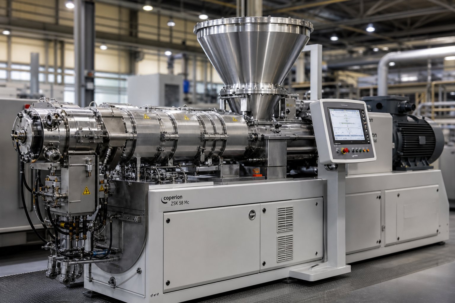
What a Twin Screw Compounding Extruder Actually Does
When your compound pellets show inconsistent color, uneven filler distribution, or unexplained degradation, the root cause almost always traces back to how your machine processes material. Before diagnosing what goes wrong, you need a sharp understanding of what the equipment is designed to do in the first place.
What Defines a Twin Screw Compounding Extruder
A twin screw compounding extruder is a machine that uses two intermeshing, co-rotating or counter-rotating screws inside a heated barrel to melt, mix, and homogenize polymers with additives, fillers, and reinforcements. Its core purpose is to create entirely new material formulations — not to shape finished products like pipes, films, or profiles. That distinction matters more than most processors realize.
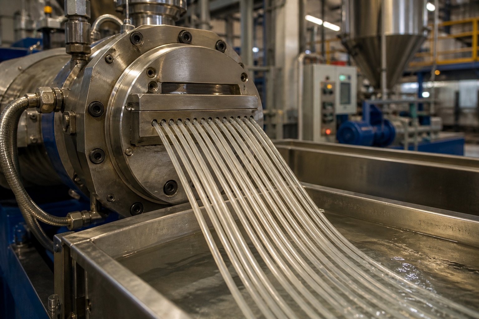
Think of it this way: a profile extruder pushes molten plastic through a shaping die. A compounding extruder, on the other hand, takes a base polymer and intimately blends it with secondary materials — colorants, flame retardants, glass fiber, mineral fillers, stabilizers — to produce a uniform compound. The output is typically pellets, cut from strands at a strand die or formed through an underwater pelletizer. Those pellets then become the raw material for downstream forming processes like injection molding or film extrusion.
This is what separates compounding from general-purpose extrusion. You're not making a product shape. You're engineering a material recipe at the molecular and micro-structural level.
Why Compounding Demands Twin Screws
So why can't a simpler machine handle this job? Compounding demands three capabilities that only twin screws deliver simultaneously: positive conveying, self-wiping action, and modular screw configurations.
Positive conveying means the intermeshing flights physically push material forward rather than relying solely on frictional drag against the barrel wall. This gives you consistent throughput regardless of material viscosity or filler loading. Self-wiping action — where one screw continuously sweeps the surface of the other — prevents material from stagnating and degrading inside the barrel. And modularity is what truly sets these machines apart: engineers can rearrange conveying elements, kneading blocks, and mixing elements along the screw shaft to fine-tune mixing intensity, residence time, and thermal history for each specific formulation.
A compounding twin screw extruder gives processors the ability to dial in exactly the right balance between shear energy and gentle conveyance. Too much shear, and you degrade the polymer. Too little, and your fillers remain as undispersed agglomerates. Every engineering decision — screw configuration, barrel zone temperatures, venting strategy, L/D ratio — directly shapes the quality of the final compound.
Twin screw compounding extruders are the industry standard for both formulation development and production-scale compounding because no other equipment architecture offers the same combination of modular flexibility, self-wiping reliability, and precise control over every stage of the mixing process.
Each of those engineering decisions carries real consequences for compound quality and machine uptime — consequences that become painfully visible when even one parameter drifts out of its operating window.
Compounding vs Extrusion vs Blending Defined
Here's where a surprising number of processors get tripped up — they use the terms compounding, extrusion, and blending interchangeably. These are not the same process. Confusing them leads to mismatched equipment choices, incorrect process parameters, and compounds that never hit spec. Let's draw the lines clearly.
Compounding Defined and Distinguished from Extrusion
Compounding is the process of melt-mixing a base polymer with one or more additives — fillers, stabilizers, pigments, reinforcements — to engineer a new material with specific target properties. The goal is material creation. You're building a recipe at the melt level, and the typical output is uniform pellets ready for downstream forming. A twin screw compounding extruder handles this job by feeding ingredients into the barrel, melting and intimately mixing them through carefully sequenced screw elements, and pushing the homogenized melt through a strand die or into an underwater pelletizer.
Extrusion, by contrast, is a forming process. It takes an already-formulated material — often those very pellets produced during compounding — and shapes it into a continuous profile, film, pipe, or sheet by forcing the melt through a shaping die. The purpose isn't to change the material's formulation. It's to give it geometry. An extruder for polymer profile production, for instance, cares about dimensional accuracy and surface finish rather than dispersive mixing quality.
The confusion is understandable because both processes use screw extrusion equipment. But the intent is fundamentally different: one creates materials, the other creates shapes.
Where Blending Fits In
Blending sits inside the broader compounding category. It refers specifically to combining two or more polymers — think PC/ABS alloys, PP/EPDM blends, or PA/PPO combinations — to achieve a property profile that neither resin delivers alone. You might blend a rigid polymer with an elastomer to balance stiffness and impact strength, or combine an amorphous resin with a semicrystalline one for improved dimensional stability.
What makes blending particularly demanding is that most polymer pairs are immiscible. Achieving a fine, stable morphology — where one phase is uniformly dispersed as small droplets within the other — requires both distributive and dispersive mixing. Twin screw extrusion excels here because modular screw configurations let engineers position kneading blocks precisely where the blend morphology needs to develop, controlling droplet breakup through targeted shear and extensional flow.
The table below breaks down all three processes side by side — a comparison that clarifies exactly where each fits in the plastics processing chain and what plastic compounding equipment each one typically requires.
| Process | Purpose | Typical Output | Equipment |
|---|---|---|---|
| Compounding | Melt-mix polymer with additives, fillers, or reinforcements to create a new material formulation | Pellets (strand-cut or underwater-pelletized) | Twin screw compounding extruder with strand die or pelletizer |
| Extrusion | Shape an already-formulated material into a continuous geometric form | Profiles, pipes, films, sheets, coatings | Single screw or twin screw extruder with shaping die |
| Blending | Combine two or more polymers to achieve a balanced property profile (subset of compounding) | Pellets of polymer alloy or blend | Twin screw extruder with intensive mixing screw configuration |
Notice the equipment column — compounding and blending both rely on twin screw technology because the mixing demands are far beyond what simple melt conveyance can deliver. That raises an obvious question: what exactly makes twin screws mechanically superior to single screw designs for these tasks?
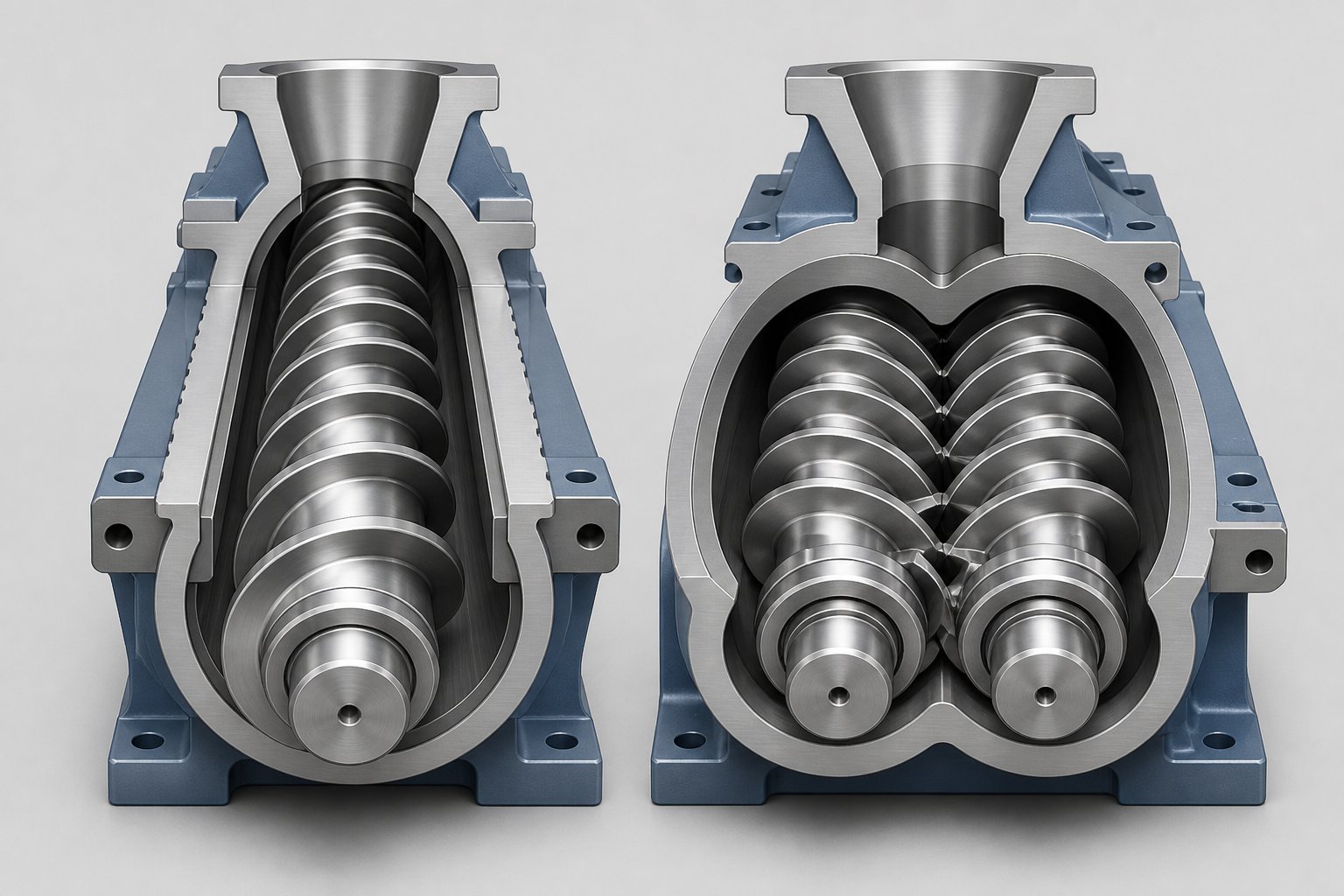
Single Screw vs Twin Screw Extruder Side by Side
The answer comes down to how each machine moves and works the material. These aren't just two versions of the same concept — they rely on fundamentally different conveying mechanics, and those mechanics dictate everything from mixing quality to filler loading limits.
How Single Screw and Twin Screw Extruders Differ Mechanically
A single screw extruder uses one rotating screw inside a smooth barrel. Material moves forward primarily through drag flow — friction between the polymer and the barrel wall drags melt along the screw channel. This mechanism works well when the feed is consistent pellets and the job is straightforward melting and pressure generation. But it creates a problem for compounding: the material essentially rides along with the screw rather than being actively worked between independent mechanical surfaces.
Twin screw extruders, sometimes called double screw extruders, operate on a completely different principle. Two intermeshing screws rotate inside a figure-eight barrel bore, and their overlapping flights create positive displacement conveying. Material is physically pushed forward by the intermeshing geometry rather than depending on barrel-wall friction. Imagine two gears transferring material between their teeth — that's closer to how a twin screw extruder machine handles feed.
This mechanical difference has cascading effects. Positive displacement means twin screw extruders can handle powders, low-bulk-density fillers, and inconsistent recycled feedstock that would starve or surge in a single screw system. The intermeshing zone also generates intense shear and extensional flow exactly where material transfers between screws, creating mixing events that a single screw simply cannot replicate. And because one screw continuously wipes the other's surface, material stagnation — a major source of thermal degradation — is virtually eliminated.
Performance Comparison for Compounding Applications
The table below puts these differences into practical terms across the parameters that matter most when you're evaluating screw extruders for compounding work.
| Parameter | Single Screw Extruder | Twin Screw Extruder |
|---|---|---|
| Mixing Efficiency | Low to moderate; limited to shear along barrel wall | High; intermeshing creates both dispersive and distributive mixing |
| Throughput Flexibility | Throughput tied directly to screw speed | Throughput adjustable independently of screw speed via starve feeding |
| Residence Time Distribution | Broad and difficult to control | Narrow and controllable through screw configuration |
| Self-Wiping Capability | None; material can stagnate in channels | Full self-wiping in co-rotating designs; minimizes degradation |
| Modular Screw Design | Fixed screw geometry; changes require a new screw | Fully modular; elements rearranged on a splined shaft |
| Venting Capability | Limited; requires special screw sections | Excellent; multiple vent ports with controlled melt seals |
| Filler Loading Capacity | Limited; typically below 40% by weight | High; routinely handles 60–80% filler with side stuffers |
| Typical Application | Pipe, profile, film, and sheet extrusion from pre-compounded pellets | Compounding, masterbatch, reactive extrusion, recycling, polymer blends |
The pattern is clear. Every parameter critical to compounding — mixing intensity, residence time control, modularity, venting, filler capacity — favors twin screw extruders. That's not a matter of one architecture being "more advanced." It's a matter of mechanical fit: the positive-displacement, self-wiping, modular design of twin screws was engineered specifically for the demands of material formulation.
When a Single Screw Still Makes Sense
Does this mean single screw extruders have no role in compounding? Not quite. For light-duty tasks — color concentrate letdown at low percentages, simple additive incorporation into a pre-compounded base, or remelting an already uniform pellet for direct sheet extrusion — a single screw can be perfectly adequate. The material doesn't need intensive mixing; it needs stable melting, consistent pressure, and reliable output to the die.
The mistake engineers make is assuming that what works for simple additive letdown will also work for dispersing nano-fillers, blending immiscible polymers, or processing high-moisture recycled feedstock. It won't. Those tasks demand the mechanical advantages only twin screws provide — and choosing the wrong architecture doesn't just reduce quality; it creates the exact processing problems covered later in this article.
Yet even within the twin screw category, the choice isn't finished. Co-rotating and counter-rotating configurations serve very different roles, and selecting the wrong one introduces its own set of compounding headaches.
Co-Rotating vs Counter-Rotating Configurations Compared
Both configurations use twin screws inside a figure-eight barrel bore. Both offer positive conveying advantages over single screw designs. But the direction those screws rotate — same way or opposite — changes everything about shear intensity, material flow patterns, residence time, and ultimately, which compounding jobs the machine can handle well.
Pick the wrong configuration, and you'll fight the machine on every run. Here's how to match the rotation to the task.
Co-Rotating Intermeshing Twin Screw Extruders
In a co-rotating twin screw extruder, both screws turn in the same direction — either both clockwise or both counterclockwise. This creates a distinctive figure-eight flow pattern where material continuously transfers from one screw to the other at the intermeshing zone. Imagine the polymer melt tracing an infinity loop as it moves down the barrel. That constant hand-off between screws is what produces the configuration's defining strengths.
First, self-wiping action. Because the flights of one screw sweep across the surface of the other during rotation, material can't stagnate or adhere. Dead zones are virtually eliminated. This matters enormously for heat-sensitive polymers and long production runs where even small amounts of stagnant material degrade, carbonize, and eventually contaminate the product stream.
Second, intense mixing. The intermeshing region generates high shear stress as material passes between the screws and between screw flights and the barrel wall. Add kneading blocks into the screw configuration, and you introduce elongational flow components that are critical for breaking apart filler agglomerates and refining polymer blend morphology. As Technovel's extrusion specialists note, the combination of shear fields between screws and barrel — along with the free configurability of screw elements — allows processors to deliberately control where and how much energy enters the material.
Third, operational flexibility. Co-rotating twin-screw extruder designs dominate the compounding industry because they handle the broadest range of applications: filled compounds with mineral or glass reinforcement, polymer blends and alloys, color masterbatch, reactive extrusion involving grafting or chain extension, and even nanocomposite production with carbon nanotubes or cellulose nanofibers. The modular screw architecture lets engineers reconfigure the same machine for vastly different formulations simply by rearranging elements on the shaft.
High screw speeds — commonly 300 to 900+ rpm on modern machines — drive high throughput rates while maintaining the mixing intensity that compounding demands. If your application requires intensive distributive and dispersive mixing, rapid melting, devolatilization, or reactive processing, co-rotating is almost always the correct starting point.
Counter-Rotating Intermeshing and Parallel Configurations
Counter-rotating extruders flip the script. The twin screws turn in opposite directions, and the material flow mechanism changes fundamentally. Instead of transferring between screws in a figure-eight pattern, material gets drawn into roughly closed C-shaped chambers between the screw flights and moves forward in discrete pockets. Think of two meshing gears pulling material through — the conveying action resembles positive displacement pumping more than the open-channel mixing characteristic of co-rotating designs.
This creates a calendering effect at the intermeshing zone. Material passing between counter-rotating screws undergoes compressive and elongational deformation rather than the high-shear kneading typical of co-rotating machines. The result is gentler, more controlled mixing with significantly less shear-induced heat generation. For materials that degrade easily at elevated temperatures — rigid PVC being the classic example — this gentler approach is not just preferred; it's essential.
Counter-rotating machines operate at lower screw speeds and higher degrees of fill, which keeps melt temperature low and residence time predictable. The tight intermeshing clearance also produces stable pressure buildup with minimal fluctuation — a major advantage for direct extrusion of pipes, profiles, and sheets where dimensional consistency matters.
Within the counter-rotating category, you'll encounter two distinct geometries. A conical twin screw extruder uses screws that taper from a large diameter at the feed end to a smaller diameter at the discharge. This converging barrel geometry naturally compresses material as it moves forward, providing high torque at the feed zone (where the large diameter gives mechanical advantage) and efficient pressure generation at the die end. Conical counter-rotating designs are the workhorse of PVC pipe and profile extrusion. Parallel counter-rotating extruders, by contrast, maintain a constant screw diameter throughout and offer more uniform processing characteristics — they're less common but still found in specialty applications requiring gentle mixing with consistent shear history.
Choosing the Right Configuration for Your Application
The practical question is straightforward: does your compounding task need intensive mixing at high speed, or gentle processing with tight thermal control? The comparison table below maps the key performance parameters of co-rotating and counter-rotating twin screw extruder configurations side by side, so you can match your specific application to the right architecture.
| Parameter | Co-Rotating | Counter-Rotating |
|---|---|---|
| Screw Rotation | Both screws turn in the same direction | Screws turn in opposite directions |
| Self-Wiping | Full self-wiping; minimal dead zones | Limited self-wiping; material retained in C-shaped chambers |
| Speed Range | High (typically 300–900+ rpm) | Low to moderate (typically 10–150 rpm) |
| Mixing Intensity | High shear and elongational mixing; excellent distributive and dispersive capability | Moderate; calendering-based dispersive mixing with lower shear |
| Residence Time Distribution | Narrow and highly controllable via screw configuration | Very narrow in conical designs; broader in parallel counter-rotating |
| Typical Applications | Filled compounds, polymer blends, masterbatch, reactive extrusion, nanocomposites, recycling | PVC pipe and profile, heat-sensitive materials, direct extrusion forming |
| Throughput Range | Wide range; scalable from lab (kg/h) to production (tons/h) | Moderate; optimized for stable output in direct extrusion |
Notice the pattern. Co-rotating configurations are built for versatility and mixing power — they handle the chaotic complexity of compounding different formulations on the same production line. Counter-rotating configurations are precision tools for specific material families where thermal sensitivity overrides the need for mixing intensity.
Most compounding operations processing engineering plastics, masterbatch, recycled materials, or filled compounds will land squarely in the co-rotating column. If you're running rigid PVC and need the lowest possible melt temperature with stable die pressure, counter-rotating — especially the conical twin screw extruder variant — is your machine.
Choosing the correct rotation direction sets the foundation. But even the right configuration will underperform if the screw design itself — the specific arrangement of conveying elements, kneading blocks, and mixing sections along the barrel length — isn't engineered to match your formulation's demands. That's where L/D ratio selection and screw element design take center stage.
Screw Design Principles and L/D Ratio Selection
Here's the part most equipment discussions skip entirely — and it's arguably the single most impactful engineering decision you'll make. You can choose the right rotation direction, buy a premium twin-screw extruder machine, and still produce poor compounds if the screw design and L/D ratio don't match your formulation's processing demands. These two parameters determine how much working length you have, where mixing occurs, how long material stays in the barrel, and whether your compound exits the die properly devolatilized or riddled with voids.
Let's break both down in practical terms.
What L/D Ratio Means and Why It Matters
L/D ratio — length-to-diameter ratio — is simply the screw's working length divided by its nominal diameter. A 50 mm diameter screw with a 2,000 mm working length has a 40:1 L/D ratio. Sounds like a basic spec, but this number dictates the available processing real estate for every unit operation your compound requires: solids conveying, melting, mixing, venting, and pressure building. Each of these operations needs dedicated barrel length. Run out of space, and you're forced to compromise — usually on mixing quality or devolatilization, which shows up immediately in pellet quality.
For most compounding applications, twin screw extrusion process designs fall within the 32:1 to 48:1 L/D range. What drives you toward the short or long end of that window? Four factors:
- Number of unit operations: A simple color compounding job — feed, melt, mix, pelletize — fits comfortably at 32:1 to 36:1. Add side feeding of fillers, a secondary mixing zone, and a vacuum vent, and you'll need 40:1 or longer.
- Required residence time: Reactive extrusion applications — grafting maleic anhydride onto polyolefins, chain-extending PET, or crosslinking silane compounds — need the polymer melt to spend enough time in the reaction zone for chemistry to complete. Longer L/D ratios of 44:1 to 48:1 provide that time without sacrificing throughput.
- Filler loading level: High-fill compounds (60–80% CaCO3, talc, or barium sulfate) typically require split feeding via side stuffers positioned partway down the barrel. Each side-stuffer port, along with its downstream mixing section, consumes barrel length. These formulations routinely demand 40:1 or greater.
- Venting requirements: Multi-stage devolatilization — common when processing hygroscopic polymers or recycled materials with high moisture — requires separate vent ports, each preceded by its own melt seal zone. Every vent stage adds roughly 4 to 8 diameters of barrel length.
The takeaway is straightforward. Short L/D ratios (32:1 or below) suit thermally sensitive materials and simple formulations that don't need extensive venting or multiple feed points. Long L/D ratios (40:1 to 48:1) give you room for complex, multi-stage processes. Choosing too short an L/D for a demanding formulation forces you to run slower or accept incomplete mixing — choosing too long wastes energy, increases residence time unnecessarily, and risks thermal degradation in materials that can't tolerate the extended heat exposure.
Screw Element Types and Modular Design
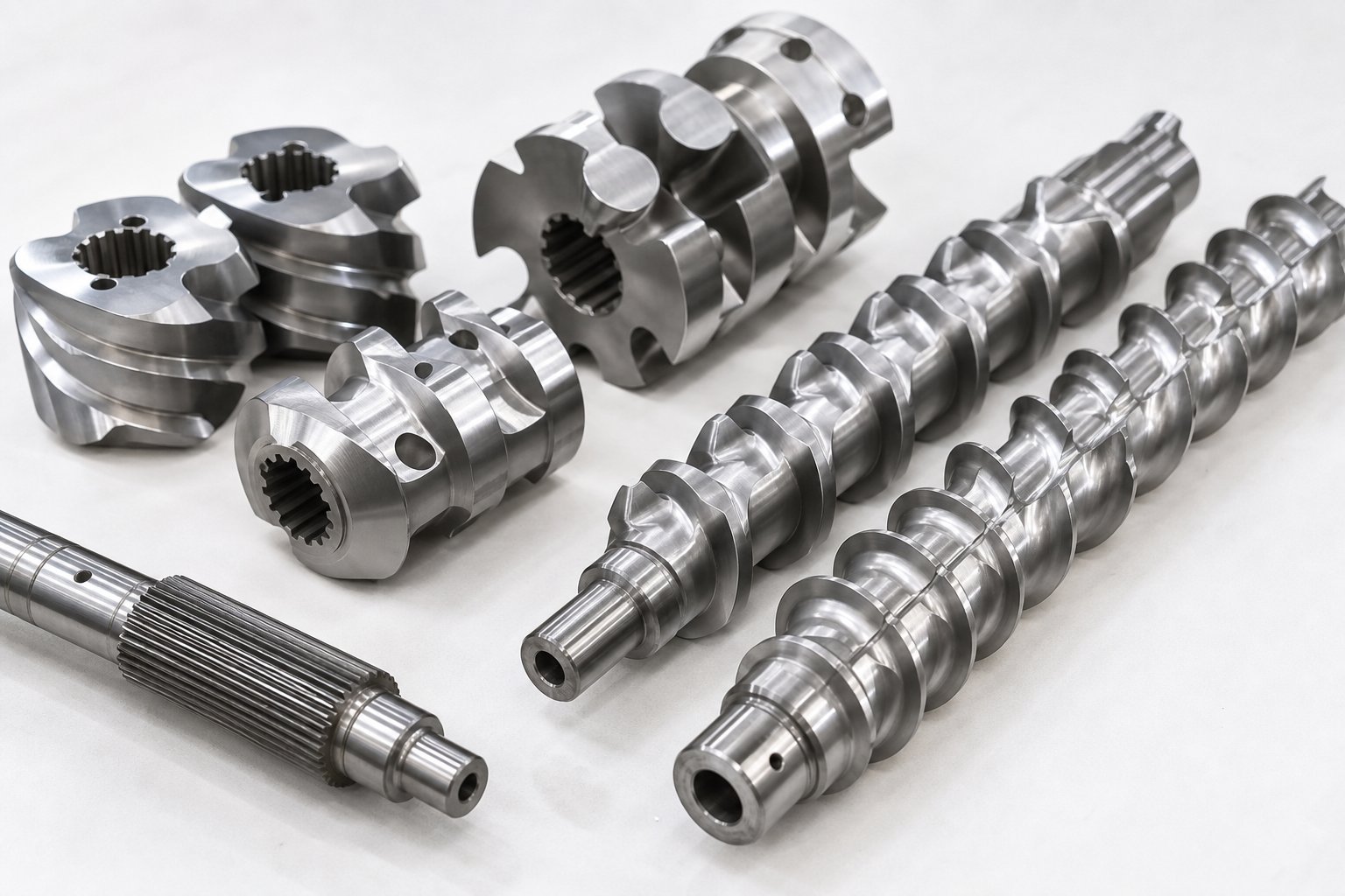
The L/D ratio gives you the playing field. Screw element selection decides how you use it. This is where double screw extruder machine designs become genuinely powerful — the modular architecture of twin screws lets engineers assemble entirely different screw configurations on the same splined shaft, transforming the machine's behavior without changing a single piece of hardware beyond the elements themselves.
Every screw profile is built from three primary element categories, each performing a distinct role in the twin screw extrusion process:
- Conveying elements (forward pitch): These are the workhorses of material transport. Deep-flighted forward conveying elements move material downstream with minimal shear input. They dominate the feed zone, where the priority is pulling raw material into the barrel efficiently, and the discharge zone, where the goal is building die pressure. Pitch variations — tighter pitch generates more pressure, wider pitch increases volumetric throughput — allow engineers to fine-tune conveying behavior along the screw length.
- Reverse conveying elements (left-handed pitch): These elements push material backward, creating restrictive melt seals. Placing a short reverse element upstream of a vent port forces the screw channels to fill completely, forming a pressure dam that prevents vent flooding. Reverse elements also increase local fill level and residence time, which can be beneficial for mixing — or destructive if overdone on heat-sensitive materials.
- Kneading blocks: The primary mixing elements in any twin screw configuration. A kneading block consists of a series of lobed disks stacked at offset angles — commonly 30, 45, 60, or 90 degrees. The stagger angle determines the balance between distributive mixing (spreading material uniformly) and dispersive mixing (breaking apart agglomerates through high shear). Narrow stagger angles like 30 degrees provide gentle, forward-conveying distributive mixing. A 90-degree stagger — known as a neutral kneading block — conveys nothing forward and maximizes shear intensity. NC State Extension's research on screw functionality confirms that reverse kneading blocks push material backward and create maximum restriction, making them the most aggressive mixing option in the toolbox. Wider kneading disks promote dispersive mixing, while narrower disks lean toward distributive action.
- Toothed mixing elements: These specialized elements feature rows of teeth rather than continuous flights. They generate distributive mixing through splitting and recombining material streams without the intense shear that kneading blocks produce. Toothed elements are valuable for blending operations where you need thorough homogenization without risking fiber breakage in glass-fiber compounds or droplet over-refinement in polymer blends.
- Blister rings and restriction elements: Solid or near-solid elements that create flow restrictions at specific barrel positions. They're used to build melt seals for vacuum venting zones or to separate functional zones with different fill levels. A blister ring forces all material through a narrow annular gap, generating a pressure spike that isolates upstream and downstream sections.
An engineer designing a screw configuration arranges these elements sequentially along the shaft to create distinct functional zones — and each zone handles a specific stage of the compounding process. A typical compounding screw profile might look like this: wide-pitch conveying elements in the feed zone to accept raw material, transitioning to tighter-pitch compression elements for initial densification, followed by an aggressive kneading block section for melting and primary mixing, then forward conveying elements to decompress the melt ahead of a vent port, a reverse element to seal the vent zone, another kneading section for secondary mixing after side-fed filler addition, and finally tight-pitch conveying elements for pressure buildup at the die.
This modular approach is what makes compounding machinery built around twin screw architecture so remarkably versatile. The same physical machine — same barrel, same gearbox, same motor — can process a 70% calcium carbonate filled PE compound in the morning and a 15% glass fiber reinforced nylon after lunch. All that changes is the arrangement of elements on the screw shaft and the barrel temperature profile. No other extrusion technology offers this level of process flexibility from a single platform.
Screw element selection and arrangement is the most powerful process variable available to compounding engineers — it determines mixing intensity, residence time, shear history, and devolatilization capacity, all within the same machine frame.
Yet even a perfectly configured screw profile can't overcome one persistent problem: volatiles trapped in the melt. Moisture, air, residual monomers, and reaction byproducts all need a way out — and how you design the venting scheme determines whether those volatiles escape cleanly or show up as bubbles, splay, and surface defects in your finished pellets.
How Venting and Devolatilization Work in a Plastic Twin Screw Extruder
Bubbles in pellets. Splay marks on molded parts. Unexplained molecular weight loss in your compound. These symptoms share a single upstream cause: volatiles that never left the melt during compounding. Moisture, entrapped air, residual monomers, and reaction byproducts all become quality killers if they remain locked inside the polymer matrix when pellets are cut at the die face. And here's the catch — most downstream processors running single screw machines have zero venting capability. Whatever volatiles your compounding machines leave behind will only reveal themselves later, as surface defects, voids, or degraded properties in the finished part.
That makes venting one of the most consequential — and least discussed — unit operations in twin screw compounding.
Why Venting Is Essential in Compounding
Every compounding formulation introduces volatile species into the barrel. Water arrives with hygroscopic polymers like nylon, PET, and polycarbonate, or with mineral fillers that carry surface moisture. Air gets entrained when low-bulk-density powders — talc, calcium carbonate, fumed silica — are fed into the extruder through side stuffers. Reactive extrusion processes generate gaseous byproducts: water of condensation from chain extension, alcohol from silane crosslinking, or acetic acid from certain coupling agents. Even pre-dried pellet-fed systems trap interstitial air between granules during feeding.
If these volatiles stay in the melt, they nucleate voids inside the pellet. Those voids collapse or re-expand during downstream processing, producing splay, silver streaks, and porosity. Worse, moisture at high melt temperatures triggers hydrolysis in condensation polymers, permanently breaking chains and destroying mechanical properties. A nylon 6,6 compound pelletized with just 0.1% residual moisture can lose significant tensile strength before it ever reaches an injection mold.
A plastic twin screw extruder accommodates venting through a clever use of its modular screw architecture. Engineers position reverse conveying elements or restrictive kneading blocks at specific locations along the screw profile, creating fully filled "melt seals" that act as pressure dams. Immediately downstream of each melt seal, forward conveying elements with wide pitch create a partially filled, low-pressure zone. It's in these decompression zones — where the screw channels are only partially full of melt — that vent ports are located. The low fill level exposes thin films of polymer surface to the vent opening, giving trapped volatiles a path to escape.
Effective devolatilization depends on creating thin melt films in partially filled screw channels — the thinner the film, the shorter the diffusion path for volatiles migrating from the melt interior to the exposed surface.
Atmospheric vs Vacuum Venting
Not all venting situations demand the same level of extraction. The two primary approaches — atmospheric and vacuum — serve different roles, and most compounding lines use both.
Atmospheric venting uses open vent ports on the barrel that allow moisture, air, and volatile gases to escape at ambient pressure. No vacuum pump, no piping — just an open barrel section positioned over a low-fill screw zone. This approach works well for removing large volumes of entrained air, particularly at side-feeder locations where low-bulk-density powders carry substantial air into the barrel. As industry expert Adam Dreiblatt explains, atmospheric vents downstream of side feeders are designed specifically to release the air introduced with particulate fillers — and the lower the filler's bulk density, the more air volume requires venting.
Atmospheric venting is sufficient for pre-dried materials with moderate volatile content, or as a first-stage removal of bulk moisture before a downstream vacuum stage finishes the job. Its simplicity is an advantage: fewer components, lower maintenance, and no risk of vacuum-related melt foaming.
Vacuum venting connects the vent port to a vacuum pump system, reducing the pressure above the melt surface to increase the driving force for mass transfer. When you lower the partial pressure of the volatile species above the melt, you shift the thermodynamic equilibrium — volatiles that would stay dissolved at atmospheric pressure now have enough driving force to diffuse out of the polymer. Most compounding lines operate vacuum vents in the range of 100 to 300 mbar (approximately 20 to 27 inches of mercury).
Vacuum venting is essential when you need to hit very low residual volatile targets — for food-contact compounds, medical-grade materials, or hygroscopic polymers prone to hydrolytic degradation. It's also critical for recycled and post-consumer materials, which often arrive with inconsistent and elevated moisture levels that atmospheric venting alone can't handle. Compounding recycled feedstock without vacuum venting is a recipe for porous pellets and unpredictable downstream performance.
A practical rule of thumb from devolatilization engineering: each vacuum vent stage can reduce volatile concentration by roughly an order of magnitude. A single vent might bring 1% moisture down to 0.1%. A second vent stage drops it further toward 0.01%. This is why machines processing solvent-laden polymer solutions or high-moisture recycled streams often feature three or four vacuum vent ports in sequence — each stage peeling away another layer of residual volatiles.
Vent Port Placement and Process Design
Where you place vents along the barrel matters as much as whether you use atmospheric or vacuum extraction. Position a vent incorrectly, and you'll either flood it with melt or fail to extract volatiles efficiently.
The foundational rule is straightforward: every vent port must sit in a partially filled screw zone, sandwiched between an upstream melt seal and a downstream conveying section. The upstream melt seal — typically formed by reverse elements or an aggressive kneading block — prevents the vacuum from pulling air backward through the machine. The downstream conveying elements ensure material moves away from the vent opening rather than backing up into it. If the backup length — the length of filled screw needed to develop die pressure — creeps upstream and reaches the vent opening, melt flows out of the vent port, blocking it and shutting down devolatilization entirely.
Multiple vent ports become necessary for demanding applications. A screw extruder granulator line processing high-moisture recycled polyester, for example, might use an atmospheric vent near the feed zone for bulk air removal, a second atmospheric vent at the side feeder for filler air displacement, and one or two vacuum vents in the downstream section for final devolatilization. Each vent stage requires its own melt seal, its own decompression zone, and enough barrel length to generate the thin melt films needed for efficient mass transfer.
Designing a venting scheme that actually works — rather than one that floods, under-vents, or wastes barrel length — follows a logical sequence:
- Identify the volatiles to remove: Determine whether you're dealing with moisture, air, residual monomers, reaction byproducts, or a combination. Each has different vapor pressures and diffusion characteristics that affect extraction difficulty.
- Determine the required vacuum level: Atmospheric venting handles bulk air and moderate moisture. Low residual targets (below 0.05%) typically require vacuum in the 100–200 mbar range. Ultra-low specifications for food or medical applications may push vacuum levels even lower.
- Position the melt seals: Each vent port needs a dedicated upstream melt seal. Place reverse elements or restrictive kneading blocks at the correct barrel positions to create the pressure dams that isolate the vent zone from adjacent processing sections.
- Select vent port locations: Position each vent in the partially filled zone immediately downstream of its melt seal. Ensure enough conveying length between the vent and the next melt seal or die to prevent backup flooding. Side vents or heated vent inserts can reduce contamination from polymer buildup in the vent housing.
- Size the vacuum system: Match the vacuum pump capacity to the expected volume of volatiles. Under-sizing leads to poor vacuum levels and incomplete devolatilization; over-sizing wastes energy. Consider whether a liquid-ring pump, dry-running pump, or roots-type blower best suits the vapors being extracted.
Each of these steps consumes barrel length — which circles back directly to L/D ratio selection. A twin screw compounding extruder with a 32:1 L/D might accommodate a single vacuum vent for a straightforward formulation. Add a second vent stage, a side feeder with its own atmospheric vent, and a reactive mixing zone upstream, and you'll quickly find yourself needing 44:1 or longer. The venting scheme can't be an afterthought. It must be designed into the screw and barrel layout from the start, or you'll spend your production hours fighting vent floods, chasing residual specs, and wondering why your pellets never come out clean.
Venting removes what shouldn't be in the compound. But some of the toughest compounding challenges have nothing to do with volatiles — they come from the materials themselves. High filler loadings that wear barrels within weeks, immiscible polymer blends that refuse to develop stable morphology, and recycled feedstock with contamination that no vent port can fix all demand material-specific process strategies.
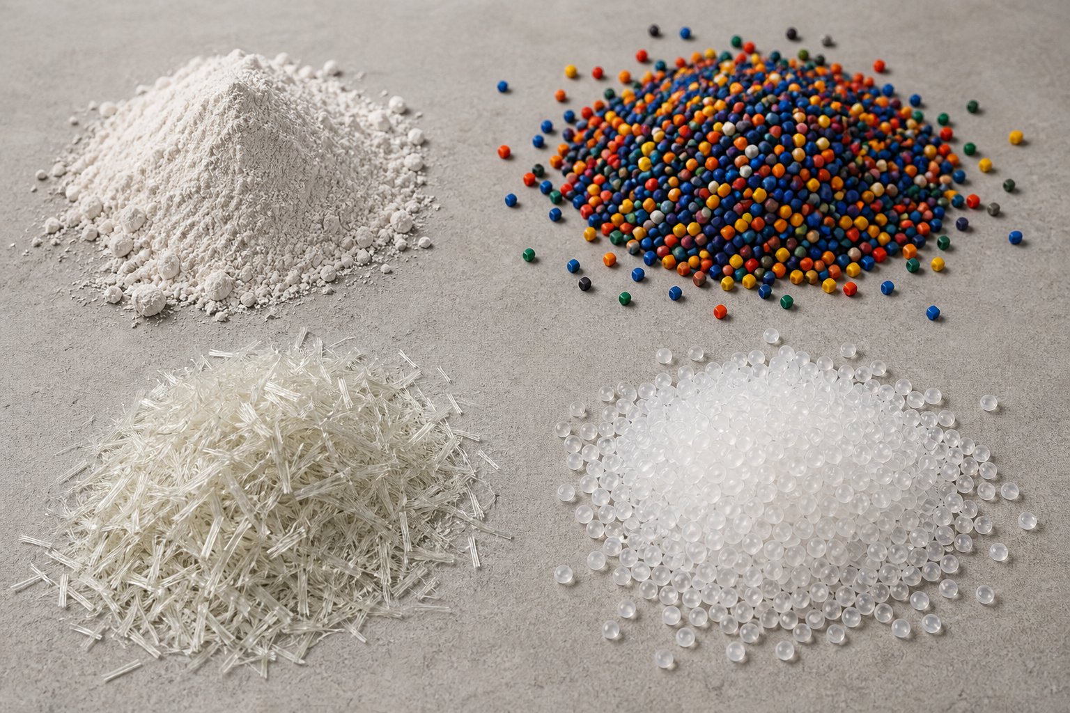
Material-Specific Compounding Challenges and Solutions
Every formulation punishes your equipment and process in its own way. A screw configuration that produces flawless 40% talc-filled polypropylene compounds may completely fail when you switch to 70% calcium carbonate in polyethylene — even on the same machine, at the same screw speed. The fillers are different, the polymer matrices behave differently, and the failure modes have nothing in common.
This is where general-purpose advice stops being useful. Real compounding performance depends on matching process parameters — screw design, barrel temperature profiles, feed strategy, and venting — to the specific demands of the material you're running. Below, the four most common application categories are broken down with the practical guidance engineers actually need.
High-Filler-Loading Compounds
Imagine trying to incorporate 70% or 80% by weight of calcium carbonate into a polyethylene matrix. The polymer — which needs to melt, flow, and wet every particle surface — now makes up less than 30% of the formulation. That ratio inverts every assumption about how a plastic compounding machine should run.
The first challenge is feeding. Mineral fillers like CaCO3, talc, and barium sulfate arrive as fine powders with low bulk densities, meaning they carry enormous volumes of entrained air relative to their mass. You can't dump all that powder into the main feed hopper alongside polymer pellets. The air overwhelms the barrel's venting capacity, and the powder-to-pellet ratio at the feed throat starves the conveying zone. Instead, high-fill formulations require split-feed configurations — the polymer enters through the main hopper, melts in the upstream barrel zones, and then mineral filler is introduced downstream through two or three side stuffers positioned along the barrel length.
Even with split feeding, air management remains critical. As compounding specialists Roman Segiet and Mark Spalding explain, the loss-in-weight feeder should sit as close as possible above the side-feeder hopper — connected by a flexible sleeve — so the powder doesn't aerate during free-fall transport through the feed pipe. The side-feeder screws themselves should run only slightly faster than the minimum needed to prevent backup, keeping screw channels full and minimizing additional air intake.
Back vents upstream of each side feeder and front vents downstream of the incorporation zone provide escape routes for entrained air. But if the filler isn't conveyed downstream and incorporated fast enough, unincorporated powder can flood back through these vent openings — creating housekeeping nightmares and inconsistent filler levels in the product. Switching the first kneading block after the side feeder from a standard 45-degree stagger to a 30-degree wide kneading block can resolve borderline back-vent flooding by slightly accelerating downstream conveyance. Conversely, a 60-degree stagger increases residence time and fill in the incorporation zone when the filler needs more time to wet out.
Wear is the other unavoidable reality. Mineral fillers are abrasive — talc and calcium carbonate erode barrel liners and screw element surfaces with every revolution. At 70–80% loading, barrel and screw wear rates accelerate dramatically, particularly in the pressure-buildup section near the die. Extruders with high free volume — indicated by a Do/Di (outer-to-inner screw diameter) ratio of 1.65 or higher — provide deeper channels that accommodate the high volumetric demands of these formulations. And a melt pump at the discharge decouples die pressure from the extruder, reducing mechanical wear in the final barrel zones while preventing vacuum-vent blockage caused by pressure propagation upstream.
Color Masterbatch and Additive Concentrates
Masterbatch compounding is a different animal entirely. The filler is a pigment rather than a mineral, and the success metric isn't just incorporation — it's dispersion quality. An undispersed pigment agglomerate as small as 50 microns can cause visible specks, color streaks, or filter blockage when downstream processors let down the masterbatch into their base resin. Your customer sees every defect your twin screw compounding extruder failed to eliminate.
Achieving excellent pigment dispersion requires high shear in the mixing zone. Kneading blocks with aggressive stagger angles — 60-degree and 90-degree neutral blocks — generate the intense shear stress needed to break apart primary pigment agglomerates and distribute individual particles uniformly through the carrier resin. The carrier itself matters: it must melt cleanly, provide good wetting of the pigment surface, and remain compatible with the downstream processor's base polymer. A mismatch between carrier viscosity and pigment surface chemistry leads to re-agglomeration downstream, even if dispersion looked acceptable at the pelletizer.
Feed strategy plays a critical role. Coperion's process engineers recommend limiting color pigment powder in the main feed to roughly 15% of the total formulation to prevent feed-intake problems caused by powder aeration. For loadings above 20% — and masterbatch formulations routinely reach 40% to 80% pigment — split feeding between the main hopper and one or more side feeders is essential. The polymer melts upstream, forming a molten matrix ready to wet out pigment particles as they enter through the downstream side feeder.
Devolatilization also deserves attention in masterbatch production. Air entrained with pigment powder creates porosity in the pellet if it isn't vented before pelletizing. Porous pellets are weaker, more prone to strand breakage at the pelletizer, and can cause inconsistent color letdown ratios for downstream processors. A vacuum vent positioned after the final mixing zone strips residual air and any volatile components, producing dense, uniform pellets. At very high pigment loadings — approaching 80% — strands become brittle, making underwater pelletizing the more reliable cutting method.
Polymer Blends and Reactive Compounding
When you blend two immiscible polymers — say, polycarbonate with ABS, or polypropylene with EPDM rubber — you're not just mixing. You're engineering a morphology. The target is typically a fine dispersion of one polymer phase as uniformly sized droplets within a continuous matrix of the other. Droplet size directly controls the blend's mechanical properties: too large, and impact strength suffers; too small, and you may sacrifice processability or transparency.
Achieving this target morphology requires a deliberate mixing strategy. Kneading blocks positioned in the screw profile generate the shear and elongational stresses that break the dispersed phase into progressively finer droplets. But here's the nuance — excessive shear can over-refine the morphology or thermally degrade one component, while insufficient shear leaves coarse, inconsistent phase domains. Engineers working on a benchtop twin screw extruder during development often run systematic trials varying kneading block sequence, stagger angle, and screw speed to map the relationship between shear input and resulting droplet size before scaling to production.
Reactive compounding adds another layer of complexity. In reactive extrusion, chemical reactions occur inside the twin screw extruder barrel while the polymer is being processed. The machine isn't just mixing — it's functioning as a continuous chemical reactor. This demands precise temperature control to initiate and sustain the reaction, adequate residence time for chemistry to reach target conversion, and enough mixing intensity to ensure uniform reaction throughout the melt — all provided by longer L/D ratios, typically 44:1 to 48:1.
Common reactive extrusion applications include:
- Maleic anhydride grafting onto polyolefins — creating functional groups that improve adhesion to glass fibers, minerals, and polar polymers
- Chain extension of condensation polymers — rebuilding molecular weight in recycled PET or polyamides using reactive additives
- Silane crosslinking of polyethylene — introducing moisture-curable crosslinks for wire and cable insulation
- Compatibilizer synthesis in situ — forming graft copolymers at the interface of immiscible blends during processing
- Controlled degradation (vis-breaking) — deliberately reducing polypropylene molecular weight for melt-blown nonwoven applications
Each of these reactions generates byproducts — water, alcohols, unreacted monomers — that must be removed via vacuum venting downstream of the reaction zone. A polyester extruder running chain-extension chemistry, for instance, needs one or two vacuum ports positioned after the reactive mixing section to strip condensation byproducts before pelletizing. Skipping this step leaves residual volatiles that continue reacting during storage, shifting compound properties after the material has left your plant.
Recycled and Post-Consumer Materials
Recycled feedstock breaks every rule that virgin material processors rely on. Melt flow is inconsistent from batch to batch. Contamination — paper labels, adhesive residues, trace metals, mixed polymer fractions — arrives in unpredictable concentrations. Moisture content swings wildly depending on storage conditions and the efficiency of upstream washing and drying operations. And molecular weight degradation from prior processing cycles means the material you receive is already partially damaged before it reaches your extruder.
These challenges demand aggressive process adaptations. Multiple venting zones are essential — often a combination of atmospheric vents near the feed zone for bulk moisture and air removal, plus one or two vacuum vents downstream for final devolatilization. Recycled PET in particular is hygroscopic and susceptible to hydrolytic chain scission at processing temperatures; even small amounts of residual moisture cause irreversible molecular weight loss and brittleness in the finished compound.
Filtration systems — continuous screen changers or melt filters positioned between the extruder discharge and the pelletizer — catch solid contaminants that would otherwise end up as inclusions in your pellets. The screen mesh size becomes a tradeoff: finer screens catch more contamination but generate higher back pressure and require more frequent changes. Automatic screen changers that swap filter elements without stopping production are standard on high-volume recycling lines for exactly this reason.
Additive strategies also shift when processing recycled materials. Chain extenders restore molecular weight lost during prior processing cycles — critical for recycled PET and polyamide compounds. Antioxidant packages need to be more robust than those used with virgin resin because the stabilizer systems in the original material have already been partially consumed. Compatibilizers become necessary when mixed polymer streams — post-consumer HDPE contaminated with PP, for instance — can't be separated completely during sorting. Without compatibilization, the immiscible polymer fractions form weak phase boundaries that destroy impact strength and elongation.
A laboratory twin screw extruder proves invaluable at this stage. Recycled feedstock variability means what worked last month may not work with the next incoming lot. Running small-batch trials on a lab-scale machine — testing screw configurations, additive levels, and temperature profiles against each new material batch — saves hours of production downtime and tons of off-spec pellets compared to troubleshooting directly on the production line.
Across all four application categories, one component absorbs the worst punishment: the barrel. Abrasive fillers grind away barrel liners. Corrosive additives attack metallurgy from the inside. High-pressure zones in the discharge section accelerate wear at the tightest tolerances. And when barrel wear progresses beyond its limits, every other process optimization you've made — screw design, venting, feed strategy — starts losing effectiveness because the conveying and mixing geometry no longer matches the original engineering intent.
Why Barrel Selection Defines Compounding Success
Most processors treat the barrel as a static shell — a piece of hardware you bolt onto the machine and forget about until something goes visibly wrong. That mindset is expensive. The twin screw barrel is an active participant in every compounding operation. It provides the thermal interface for heating and cooling zones, withstands relentless abrasive and corrosive attack from fillers and additives, and maintains the tight tolerances with screw flights that make efficient conveying and mixing possible. When barrel performance degrades, every upstream process optimization — your carefully configured screw elements, your venting scheme, your feed strategy — starts losing effectiveness.
Understanding what goes on inside that barrel wall, how to recognize when wear has crossed the threshold, and what to look for in a replacement barrel separates plants that run smoothly from those chasing unexplained quality problems for months.
How Barrel Metallurgy Affects Compounding Performance
The barrel bore is where polymer melt meets metal under extreme conditions. Temperatures routinely reach 200 to 350 degrees Celsius. Pressures in the discharge section can exceed 100 bar. And the material flowing through — loaded with glass fibers at Mohs 5.5 to 6.5, calcium carbonate particles, titanium dioxide, or corrosive flame retardant decomposition products — grinds and attacks the bore surface with every screw revolution.
Barrel liner materials are selected specifically to resist the dominant wear mechanism in your process. The choice isn't one-size-fits-all — it's a direct function of what your compound contains:
- Nitrided steel barrels: The baseline option. Gas nitriding hardens the bore surface to approximately 950 to 1,100 HV with a case depth of 0.3 to 0.7 mm. Adequate for unfilled commodity polymers like polyethylene and polypropylene where abrasive wear is minimal. The limitation is that the hardened layer is shallow — once abrasion wears through the nitrided case, the softer substrate underneath erodes rapidly.
- Iron-boron bimetallic liners: A centrifugally cast, metallurgically bonded liner inside an outer steel shell. Bore hardness typically reaches 60 to 72 HRC with liner thickness of 2.0 to 2.5 mm. This is the dominant choice for general abrasive compounding — mineral-filled polyolefins, talc-reinforced polypropylene, glass-fiber-reinforced nylon. The high chromium and tungsten carbide content in the liner resists sliding abrasion far longer than nitrided surfaces.
- Nickel-based alloy liners: When your formulation attacks chemically — PVC releasing hydrogen chloride, halogenated flame retardants generating corrosive gases, or fluoropolymers evolving hydrogen fluoride — nickel-matrix bimetallic liners provide the passive film formation that resists chemical dissolution. Industry data shows corrosive wear rates for nitrided 4140 steel in rigid PVC service running 0.08 to 0.15 mm per 1,000 hours, compared to just 0.01 to 0.03 mm for high-nickel, high-chromium bimetallic constructions.
- Tungsten carbide liners: The premium option for severely abrasive compounds — 40% or higher glass fiber loading, ceramic microspheres, or high-throughput mineral-filled production where barrel life directly drives total cost of ownership. Coating hardness exceeds 1,100 HV, but the higher cost is justified only when the abrasion intensity warrants it.
The twin screw and barrel work as a system. A mismatch between liner metallurgy and compound chemistry creates the exact conditions for accelerated wear — and once bore tolerances open up, every performance metric suffers.
Signs of Barrel Wear and When to Replace
Barrel wear doesn't announce itself with a sudden failure. It creeps in gradually, and the symptoms often get misattributed to other causes. Here's what to watch for:
Declining output at the same screw speed. As the clearance between screw flight OD and barrel bore widens, leakage flow increases — polymer slips backward across the flight tip instead of being conveyed forward. You'll see throughput drop 8% to 15% before most operators even suspect barrel wear as the cause. The instinct is to increase screw speed to compensate, which only accelerates the wear cycle.
Loss of pressure stability. A worn bore can't maintain the tight sealing action that generates consistent die pressure. You'll notice pressure fluctuations at the melt pump or die adapter — fluctuations that weren't there six months ago and don't respond to temperature or feed-rate adjustments.
Poor mixing quality. This is the symptom that's hardest to trace back to the barrel. When bore clearances increase, the shear field between screw flights and barrel wall weakens. Kneading blocks that once generated excellent dispersive mixing now allow agglomerates to slip past. You see undispersed pigment specks, filler agglomerates, or inconsistent color distribution — and you blame the screw configuration when the real culprit is the barrel.
Increased melt temperature. Wider clearances mean more material recirculates inside the barrel rather than moving forward efficiently. The extra residence time and internal friction generate heat that shows up as elevated melt temperatures — even when barrel zone setpoints haven't changed. For heat-sensitive materials, this thermal penalty triggers degradation, discoloration, and molecular weight loss.
If your melt temperature keeps climbing despite stable barrel setpoints and unchanged screw speed, barrel wear is the most likely cause — and the most commonly overlooked one.
The reliable way to track wear progression is bore measurement at regular intervals. Using a telescoping bore gauge or laser micrometer, measure the barrel bore diameter at multiple points along its length — focusing on the high-wear zones: the feed section, kneading block regions, and the pressure-buildup section near the die. Industry practice recommends inspection every 1,500 to 2,000 operating hours as a baseline, or every 800 to 1,200 hours when processing abrasive compounds above 30% filler loading. Document each measurement in a wear log. Trends — not single readings — tell you when replacement is approaching and let you schedule the changeover during planned downtime rather than waiting for a production crisis.
Selecting Replacement and Custom Barrels
When bore measurements confirm replacement is needed, the procurement decision carries real production consequences. A poorly specified replacement barrel doesn't just cost money — it resets your wear clock to zero with an inadequate starting point. Here's what matters most:
Dimensional accuracy. The replacement barrel must match your machine's original bore geometry within tight tolerances. A parallel twin screw extruder barrel with bore dimensions even 0.05 mm off-spec creates uneven clearances that accelerate wear on one side while leaving the other underutilized. Confirm that any prospective supplier provides CMM-verified dimensional inspection data — not just nominal specifications from a catalog drawing.
Liner metallurgy matched to your application. This is where the analysis from the previous section pays off. If you're compounding glass-fiber-reinforced engineering plastics, specifying a nitrided barrel as a replacement just because it's cheaper will put you right back in the same wear situation within months. Match the liner material to your compound's abrasion and corrosion profile — iron-boron bimetallic for abrasive mineral fills, nickel-based alloys for corrosive PVC or FR compounds, tungsten carbide for severe glass-fiber duty.
Custom configurations for specific machine platforms. Not all twin screw extruder manufacturers use identical barrel designs. Bore spacing, heating channel geometry, cooling port locations, barrel segment lengths, and clamping interfaces vary across OEM platforms. Your replacement barrel supplier needs the engineering capability to produce barrels that fit your specific machine — whether it's a Coperion, Leistritz, KraussMaffei, JSW, or any other platform — without requiring mechanical modifications that compromise alignment or thermal uniformity.
Supplier responsiveness for production-critical replacements. A worn barrel waiting for a replacement that takes 16 weeks to arrive means 16 weeks of declining output, rising melt temperatures, and worsening compound quality. Evaluate suppliers not just on metallurgical capability but on lead time and willingness to expedite critical orders. Compounding producers running 24/7 operations can't afford to wait.
For operations seeking replacement or custom-engineered twin screw barrels — whether for compounding, masterbatch production, recycling, or pelletizing applications — suppliers like NANHAIYA offer parallel twin screw barrel configurations designed for high-wear processing environments. Evaluating options from specialized barrel manufacturers alongside your OEM's offerings gives you a broader view of available metallurgies, lead times, and cost structures — particularly for plants running abrasive or corrosive formulations that demand more than standard replacement parts can deliver.
The barrel sets the physical boundary conditions for everything happening inside your compounder. Get the metallurgy right, monitor wear before it silently degrades your process, and choose replacement barrels with the same engineering rigor you apply to screw design. Skip any of those steps, and you'll find yourself troubleshooting symptoms — output drops, quality drift, thermal instability — that no screw configuration change or process parameter adjustment can fix, because the root cause is the metal surrounding your screws, not the elements spinning inside them.
Troubleshooting Common Twin Screw Compounding Problems
You've selected the right barrel metallurgy, configured your screw elements for the formulation, and dialed in your venting scheme. Production starts — and something still isn't right. Output fluctuates. Pellets show discoloration. Fillers refuse to disperse. Melt oozes from vent ports. These problems hit every compounder eventually, and the difference between a quick recovery and days of lost production comes down to how systematically you diagnose the root cause.
Most twin-screw extruders share the same handful of failure modes, regardless of manufacturer or formulation. Here's what goes wrong, why it happens, and what to do about it.
Output Surging and Inconsistent Throughput
When your pelletizer line speed stays constant but pellet weight drifts up and down, or your strand diameter visibly pulses, you're dealing with output surging. This is one of the most frustrating problems on a twin screw plastic extruder because the causes can originate anywhere from the feed hopper to the discharge end.
Start at the feeder. Starve-feeding imbalances — where the gravimetric feeder's actual delivery rate fluctuates around its setpoint — create throughput waves that propagate through the entire barrel. Inconsistent raw material bulk density is a common trigger: when a new lot of powder arrives with different particle size distribution or moisture content, the feeder's calibration no longer matches the material's flow behavior. Bridging in the feed hopper, where powder compacts into an arch above the feed throat and then collapses in slugs, produces the same surging pattern.
Downstream, worn screw elements cause slippage. As conveying element flight tips wear down and clearances with the barrel bore open up, the positive displacement conveying action weakens. Material leaks backward across worn flights instead of moving forward consistently. This effect compounds over time — if you're running used extrusion equipment or machines with high accumulated hours, worn elements in the pressure-buildup zone are often the hidden culprit behind chronic surging that doesn't respond to feeder adjustments.
An improper screw speed-to-feed-rate ratio also destabilizes output. Running screw speed too high relative to the feed rate creates an excessively starve-fed condition where the screws are nearly empty. Small variations in feed delivery then represent a large percentage change in fill level, amplifying throughput oscillations. Reducing screw speed until the specific throughput (kg/hr per rpm) falls within the recommended operating window for your machine typically smooths things out.
Material Degradation and Discoloration
Yellow-tinged pellets. Brown specks. A burnt smell at the die. Thermal degradation during compounding destroys compound properties and generates scrap — and the causes are almost always traceable to excessive thermal energy input.
Barrel temperatures set too high for the polymer being processed are the most obvious source. But the more insidious cause is shear-induced viscous heating from overly aggressive kneading blocks. A 90-degree neutral kneading block section that's longer than necessary generates enormous mechanical energy input, raising melt temperature far above the barrel setpoint. The polymer doesn't care what your temperature controller reads — it responds to the actual melt temperature, which in heavily worked zones can exceed the setpoint by 20 to 40 degrees Celsius.
Dead spots — areas where material stagnates and overheats — are another degradation source. In co-rotating twin-screw extruders, self-wiping geometry minimizes this risk, but it doesn't eliminate it entirely. Material can accumulate in barrel transitions, vent housings, adapter flanges, and die channels where flow paths create recirculation zones. Regular purging and inspection of these areas catches buildup before it carbonizes and sheds black specks into the product stream.
Excessive residence time amplifies all of these effects. If your L/D ratio is longer than the formulation requires, or if throughput is running well below the machine's design capacity, material spends more time at elevated temperature than it should. The systematic approach to reducing degradation follows a clear sequence: first, review the barrel temperature profile and lower zones near the mixing sections. Second, evaluate whether kneading block sections can be shortened or replaced with less aggressive stagger angles. Third, optimize throughput — running faster through the same screw configuration reduces average residence time and limits thermal exposure.
Poor Dispersion and Undispersed Agglomerates
You pull a strand sample, stretch it thin under a light, and see specks — pigment clusters, filler agglomerates, or gel particles that should have been broken apart during mixing. Poor dispersion is a mixing zone problem, but the root cause isn't always insufficient shear.
Incorrect kneading block stagger angles are the first place to look. If your mixing section uses only 30-degree or 45-degree forward-conveying kneading elements, the shear intensity may be too low for the agglomerate strength of your filler or pigment. Switching to 60-degree or 90-degree kneading blocks increases dispersive mixing energy. But be careful — adding shear without considering the consequences discussed in the degradation section above trades one problem for another.
Feed sequence matters more than many engineers realize. Coperion's process engineering team emphasizes that introducing pigment powder through the main feed alongside polymer pellets at loadings above 15% creates feed-intake problems due to powder aeration. Side-feeding the pigment or filler into an already molten polymer stream downstream ensures proper wet-out — the liquid polymer matrix can immediately begin penetrating and breaking apart agglomerates upon contact, rather than trying to simultaneously melt pellets and disperse powder in the same zone.
Material pre-treatment is the frequently overlooked variable. Some pigments and fillers arrive with hard agglomerates that formed during storage or shipping. Pre-drying hygroscopic fillers before compounding prevents moisture-bonded agglomerates from surviving the mixing zone. In extreme cases, pre-deagglomeration in a high-intensity mixer before feeding into the extruder gives the twin screw compounding extruder a head start that no amount of kneading block optimization can replicate.
Vent Flow and Die Drool
Material flowing out of a vent port — vent flooding — forces immediate operator intervention and shuts down effective devolatilization. The cause is almost always a melt seal that isn't doing its job. As Adam Dreiblatt of CPM Century Extrusion details, melt reaches the vacuum vent when the backup length — the length of filled screw needed to generate die pressure — extends upstream far enough to reach the vent opening. This happens when the screen pack fouls, die holes partially freeze off, or screw and barrel wear in the pressure-buildup section reduces pumping efficiency over time.
The solutions depend on which mechanism is driving the backup. Fouled screens require increasing screen area or installing an automatic screen changer. Worn pumping elements need replacement. If the issue is structural — the vent port is simply too close to the discharge end — relocating the vacuum vent one barrel section upstream or adding a melt pump to decouple die pressure from the extruder's pumping section provides a permanent fix. When vacuum itself is pulling melt out — visible as a steady drop on the vacuum gauge indicating air is being sucked through the barrel — the melt-seal elements upstream of the vent aren't creating enough restriction. More aggressive reverse elements or tighter-clearance sealing discs are the corrective action.
Die drool — the slow accumulation of material around the die face — has different origins. Low-molecular-weight polymer fractions migrate to the surface and ooze from the die lip. Incompatible additives that don't fully incorporate into the melt matrix bleed out under pressure. Certain lubricants and processing aids, if overdosed, exacerbate the problem. Die design also contributes: sharp die-lip edges and improper land lengths create flow instabilities that encourage drool buildup. When evaluating used extruder equipment for a new compounding line, inspect the die adapter and strand die surfaces carefully — worn or damaged die components inherited from previous service can introduce drool issues that have nothing to do with your formulation.
Quick-Reference Troubleshooting Matrix
The table below consolidates the four major problem categories into a scannable reference you can keep near the extruder control panel. It won't replace systematic root-cause analysis, but it narrows the search space fast when production time is on the line.
| Problem | Common Causes | Corrective Actions |
|---|---|---|
| Output Surging / Inconsistent Throughput | Feeder calibration drift; raw material bulk density variation; hopper bridging; worn conveying elements; screw speed too high relative to feed rate | Recalibrate feeders for current material lot; install hopper agitator or vibrator; replace worn screw elements; reduce screw speed to increase specific throughput; verify feed-rate-to-screw-speed ratio |
| Material Degradation / Discoloration | Excessive barrel temperatures; too-aggressive kneading blocks generating shear heat; dead spots in barrel transitions or vent housings; excessive residence time from low throughput or oversized L/D | Lower barrel zone temperatures near mixing sections; shorten kneading block sections or reduce stagger angles; purge and inspect dead zones; increase throughput to reduce residence time; audit melt temperature vs. barrel setpoints |
| Poor Dispersion / Undispersed Agglomerates | Insufficient shear in mixing zone; kneading block stagger angles too low; filler or pigment fed through main hopper instead of side feeder; material not pre-dried or pre-deagglomerated | Switch to higher-angle kneading blocks (60° or 90°); implement side-feeding for fillers above 15% loading; pre-dry hygroscopic fillers; pre-deagglomerate hard pigment clusters before feeding; verify polymer is fully molten before filler introduction |
| Vent Flooding / Die Drool | Melt backup reaching vent port due to screen fouling or worn pumping elements; insufficient melt-seal restriction upstream of vent; die lip wear; incompatible additives or lubricant overdose | Increase screen area or install auto screen changer; replace worn pumping elements; use more restrictive melt-seal elements; install melt pump to decouple die pressure; inspect and refurbish die lips; review additive compatibility and dosing levels |
Every entry in this matrix connects back to the engineering fundamentals covered throughout this article — screw element selection, barrel condition, venting design, feed strategy, and L/D ratio. Troubleshooting isn't guesswork. It's the process of tracing a visible symptom back through the system to the specific parameter that drifted out of its operating window. The engineers who resolve problems quickly aren't the ones with the most experience. They're the ones who understand how each component in their twin screw compounding extruder interacts with every other — and who check the simple things first before chasing exotic explanations.
Twin Screw Compounding Extruder FAQs
1. What is the difference between a twin screw compounding extruder and a single screw extruder?
A twin screw compounding extruder uses two intermeshing screws with positive displacement conveying, self-wiping action, and modular screw elements to intensively mix polymers with fillers, pigments, and additives. A single screw extruder relies on drag flow along the barrel wall, which limits its mixing capability. Twin screws handle high filler loadings (60-80%), offer narrow residence time distribution, and support multiple vent ports — making them the standard for compounding. Single screws are better suited for simpler tasks like pipe, film, or sheet extrusion from pre-compounded pellets.
2. How do I choose between co-rotating and counter-rotating twin screw extruders?
Co-rotating twin screw extruders are the dominant choice for most compounding applications — filled compounds, masterbatch, polymer blends, reactive extrusion, and recycling — because they deliver high-speed self-wiping action, intense distributive and dispersive mixing, and broad operational flexibility. Counter-rotating extruders operate at lower speeds with gentler mixing and very narrow residence time distribution, making them ideal for heat-sensitive materials like rigid PVC. Conical counter-rotating designs are particularly common for PVC pipe and profile extrusion where low melt temperature and stable die pressure are critical.
3. What L/D ratio should I use for my twin screw compounding extruder?
Most compounding applications use L/D ratios between 32:1 and 48:1. Simple color compounding fits comfortably at 32:1 to 36:1. Adding side feeders, multiple mixing zones, or a single vacuum vent pushes the requirement to 40:1 or higher. Reactive extrusion, multi-stage devolatilization, and high-filler-loading formulations with split feeding typically demand 44:1 to 48:1. Choosing too short an L/D forces compromises on mixing or venting quality, while an unnecessarily long L/D wastes energy and increases the risk of thermal degradation from extended residence time.
4. Why is my twin screw compounding extruder producing degraded or discolored pellets?
Degradation and discoloration typically result from excessive thermal energy input. Common causes include barrel temperatures set too high, overly aggressive kneading blocks (especially long 90-degree neutral sections) generating shear heat that raises melt temperature 20-40 degrees Celsius above the barrel setpoint, material stagnating in dead zones at barrel transitions or vent housings, and excessive residence time from running low throughput on an oversized L/D machine. Systematically lower mixing-zone barrel temperatures, shorten or soften kneading block sections, purge and inspect dead zones, and increase throughput to reduce heat exposure.
5. How often should I inspect and replace the barrel on a twin screw compounding extruder?
Industry practice recommends bore measurements every 1,500 to 2,000 operating hours for standard compounds, or every 800 to 1,200 hours when processing abrasive formulations above 30% filler loading. Key wear indicators include declining output at the same screw speed, pressure instability at the die, worsening dispersion quality, and rising melt temperatures despite stable barrel setpoints. When selecting replacement barrels, match liner metallurgy to your compound's wear profile — nitrided steel for unfilled polymers, iron-boron bimetallic for mineral-filled compounds, nickel-based alloys for corrosive formulations, and tungsten carbide for severe glass-fiber applications. Specialized suppliers like NANHAIYA offer custom parallel twin screw barrels engineered for high-wear compounding environments.
Written by
Nanhaiya Technical Team
Zhoushan Nanhaiya Plastic Machinery Co., Ltd.
The Nanhaiya technical team supports screw and barrel manufacturing projects through application review, technical communication, custom manufacturing coordination, and production and quality control.
Discuss Your Application
Related Articles
More insights on screw barrel technology and plastics processing.

What Nobody Tells You About Screw Barrel For Plastic Machine Design
Oct 10, 2026
Learn how screw barrel for plastic machine design affects melt quality, throughput, and wear life. Covers geometry, resin matching, troubleshooting, and sourcing.
Read Article
Single Screw Extruder for Sheet: Stop Guessing, Start Specifying
Oct 9, 2026
Learn how to specify a single screw extruder for sheet production. Covers screw geometry, resin-specific processing, troubleshooting, and maintenance best practices.
Read Article
PE Pipe Extruder Machine: What Datasheets Won't Tell You
Oct 9, 2026
Learn how a PE pipe extruder machine works, key specs explained, material grade selection, maintenance tips, and buyer guidance beyond the datasheet.
Read ArticleLooking for something else?
Search by material, symptom or product and jump straight to the relevant page.
These are navigation suggestions based on keyword matching — not a quotation, not a delivery commitment, and not a substitute for engineering review. Final specification is confirmed by our engineers against your drawings and processed material.
Need help with screw barrel selection?
Share your machine model, processed material and application. Our team can help with pricing and technical support.