

What Is a Twin Screw Barrel Extruder and Why the Barrel Demands Attention
Defining the Twin Screw Barrel Extruder System
When engineers discuss twin screw extrusion, the conversation almost always gravitates toward screw geometry — flight pitch, kneading block arrangement, element sequencing. The barrel? It gets reduced to a passive shell. That perception is a costly oversight.
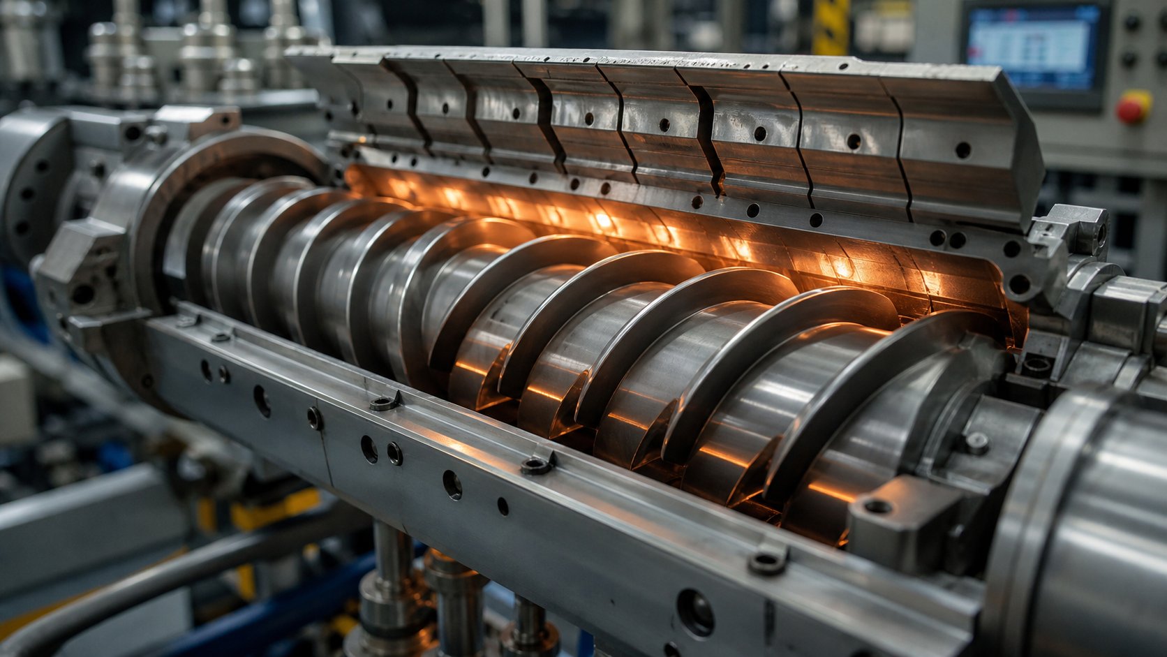
A twin screw barrel extruder is an integrated processing system in which two intermeshing screws rotate inside a precisely engineered barrel to continuously convey, melt, mix, and shape materials. The barrel serves as an active processing component — providing independently controlled heating and cooling zones, segmented modular configurations, engineered wear-resistant surfaces, and ports for venting, side feeding, and liquid injection.
This definition moves beyond the basic extruders meaning most people encounter — a machine that pushes material through a die. A twin-screw extruder is far more nuanced. It functions as a series of interconnected unit operations, and the barrel defines the thermal, pressure, and geometric environment in which every one of those operations takes place.
Why the Barrel Matters More Than You Think
Search for "twin screw extruder" online, and you'll find dozens of articles covering screw rotation direction, mixing theory, and application lists. Very few dedicate meaningful space to barrel construction, material selection, or modular segmentation strategy. Yet barrel bore tolerance directly affects mixing uniformity. Barrel metallurgy determines service life under abrasive or corrosive conditions. And barrel segment configuration — where vent ports, side feeders, and closed sections are positioned — fundamentally shapes what a twin screw extruder can and cannot do.
This article corrects that imbalance. It covers the mechanical interplay between barrel and screw, compares co-rotating and counter-rotating configurations in structured detail, examines barrel materials from nitrided steel to tungsten carbide coatings, and maps specific barrel layouts to real processing applications. Whether you're an engineer optimizing a twin screw extrusion process or a buyer evaluating replacement barrel options, the sections ahead provide the technical depth and practical guidance that generic overviews leave out.
How the Barrel and Screw System Works Together
Imagine dropping a handful of plastic pellets into one end of a machine and pulling out a perfectly homogenized, temperature-controlled melt stream from the other. Between those two points, an extraordinary amount of physics happens — and none of it is possible without the barrel and screws functioning as a single, tightly coordinated extruder system.
The screws generate conveying force, shear, and distributive mixing. But they don't operate in a vacuum. Every rotation happens inside a barrel bore that provides the containment pressure, thermal energy, and geometric boundaries the process depends on. Remove the barrel's contribution, and the screws are just spinning metal. Understanding how these components interact — zone by zone, from feed throat to die — is the foundation for getting the most out of any extruder twin screw configuration.
Material Flow from Feed Zone to Discharge
Raw material enters the system through the feed throat, typically as pellets, powder, or flake. From this point forward, it passes through a series of functional zones along the barrel length, each defined by a specific combination of barrel geometry, temperature setting, and screw element design. Here's how each zone contributes to the transformation:
Feed zone. Large-pitch, deep-flighted conveying elements on the screws pull material into the barrel. The barrel section here is usually liquid-cooled to prevent premature melting, which would cause bridging and feed instability. The open channel design and high free volume keep solid material moving forward smoothly.
Melting and transition zone. As material advances, barrel heaters raise the temperature while kneading blocks on the screws introduce mechanical shear. The combination of external heat transfer through the barrel wall and internal viscous dissipation from screw rotation gradually transforms solid feedstock into a uniform melt. Barrel temperature in this zone typically ranges from 150°C to 280°C, though high-performance polymers may require settings up to 450°C.
Mixing zone. This is where dispersive and distributive mixing reach their peak intensity. Kneading blocks, gear-type mixing elements, and specialized distributive elements on the screws work against the barrel's tight bore to generate the shear fields that break up agglomerates and distribute additives evenly throughout the melt. The barrel provides both the thermal envelope and the pressure containment that make this high-energy mixing possible.
Venting and degassing zone. Not every screw extrusion process requires venting, but many do. In these sections, large-pitch conveying elements reduce the degree of fill, expanding the melt's free surface area inside the barrel. Atmospheric or vacuum vent ports in the barrel then draw off moisture, trapped air, residual monomers, and volatile contaminants. Reverse elements upstream create a melt seal that prevents material from flowing backward into the vent opening.
Metering zone. The final barrel section stabilizes pressure and flow. Shallow-flighted forward conveying elements compress the melt into a consistent stream, building the back pressure needed to push material through the die at a steady rate. The barrel's temperature control in this zone keeps the melt at its target processing window, preventing last-stage degradation or viscosity variation.
How Barrel and Screw Interaction Drives Processing Quality
Here's where things get critical for engineers evaluating screw extruder performance. The gap between the screw flight tip and the barrel bore wall — often called the tip clearance — is typically just 0.1% to 0.5% of the barrel's internal diameter. That tiny dimension has outsized consequences.
When barrel bore tolerance is tight and consistent, material passes through a uniform shear field at every screw rotation. The result is predictable residence time distribution, even melt temperature, and homogeneous mixing — exactly what processors need for consistent product quality. When the bore wears unevenly or clearances open up beyond specification, material leaks past screw flights, shear rates drop in worn areas, and the entire melt stream becomes less uniform. You'll notice rising specific energy consumption, inconsistent output, and quality drift long before the barrel looks visibly damaged.
The barrel's role extends well beyond being a cylindrical container. In a modern twin screw barrel extruder, the barrel is an active processing partner that performs several essential functions simultaneously:
- Thermal regulation — Independent heating and cooling zones along the barrel length allow precise temperature profiling. Each barrel segment can be controlled separately, enabling processors to fine-tune melting behavior, control reaction rates, and prevent thermal degradation.
- Pressure containment — The barrel withstands the internal pressures generated by screw rotation, melt compression, and die resistance, maintaining the sealed environment required for stable screw extrusion.
- Wear resistance — Barrel bore surfaces must endure continuous abrasion from filled polymers, corrosion from chemically aggressive melts, and adhesive wear from metal-to-metal contact — all while holding dimensional tolerances measured in hundredths of a millimeter.
- Process flexibility through segmentation — Modular barrel systems let processors reconfigure zone layouts by swapping individual barrel sections, adapting the same machine to different products without purchasing entirely new equipment.
- Integration of auxiliary ports — Side feeder openings for downstream filler addition, vent ports for degassing, and liquid injection ports for reactive additives or processing aids are all engineered into specific barrel segments, giving the extruder system its multi-functional capability.
This barrel-screw interplay is what separates a well-engineered twin screw extrusion line from a machine that merely pushes material forward. The screws determine what forces act on the material. The barrel determines the environment in which those forces operate. Change one without accounting for the other, and the entire process shifts — sometimes in ways that only show up as subtle quality defects downstream.
The question, then, is not whether to pay attention to barrel design — it's which barrel configuration best matches the specific demands of your process. And that starts with understanding how different screw rotation directions fundamentally change what the barrel needs to deliver.
Co-Rotating vs Counter-Rotating Twin Screw Configurations Compared
Screw rotation direction is not a minor specification line buried in a datasheet. It reshapes everything — the flow pattern inside the barrel, the shear intensity the material experiences, the pressure profile along the extruder length, and ultimately, which applications the machine can serve. Understanding the differences between a co rotating twin screw extruder and its counter-rotating counterpart is essential for anyone making equipment or barrel configuration decisions. And yet, most comparisons skim the surface. Let's go deeper.
Co-Rotating Twin Screw Extruders and Their Advantages
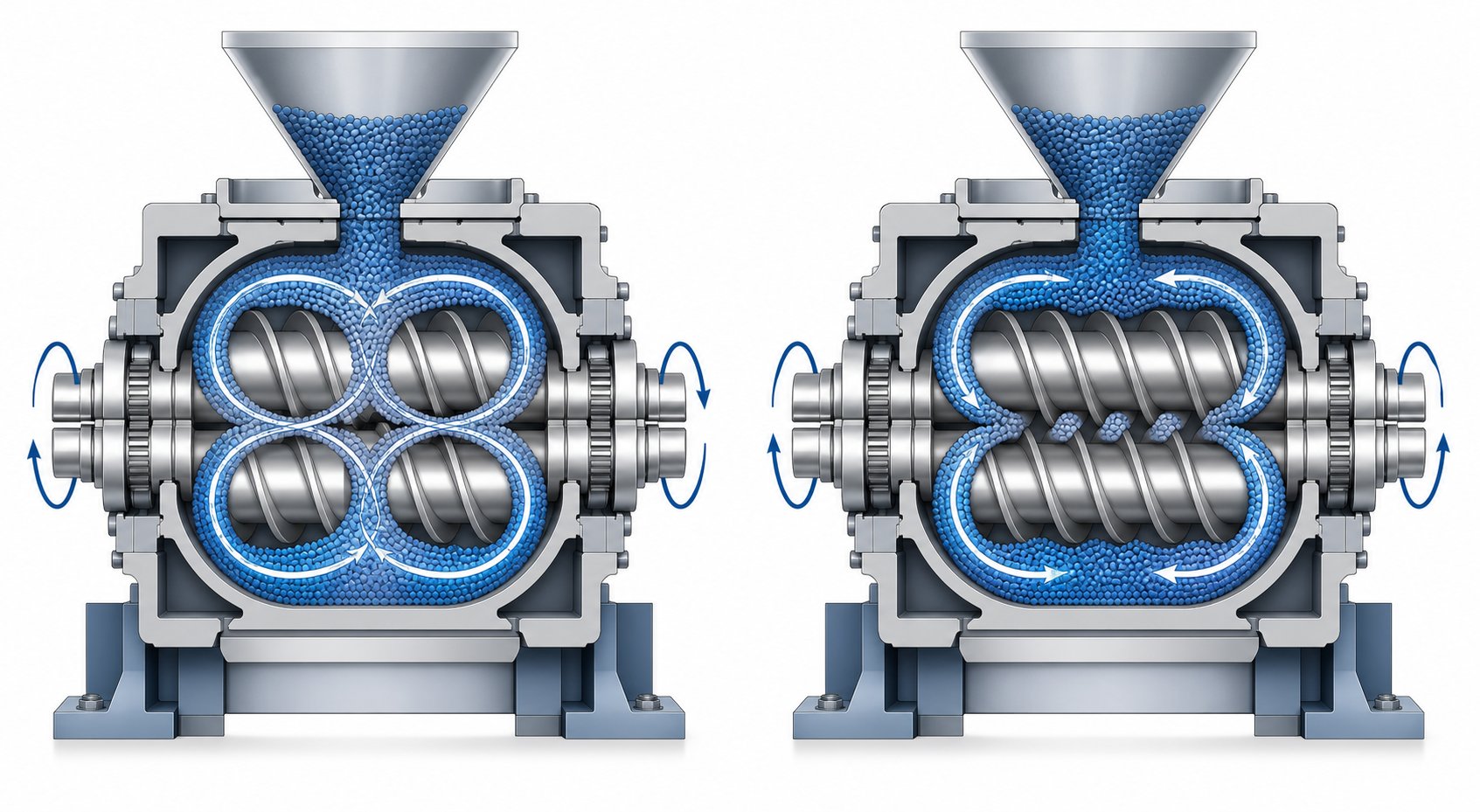
In a co-rotating configuration, both screws turn in the same direction — either both clockwise or both counterclockwise. A fully intermeshing geometry is standard, meaning the flights of one screw closely engage the channels of the other. This creates a distinctive figure-eight ("∞"-shaped) flow pattern where material is forcibly handed off from one screw to the next at each intermeshing region.
What does that mean in practice? Two things that matter enormously for processing quality.
First, the self-wiping action. Because the screws continuously sweep each other's surfaces, material cannot stagnate or adhere to the barrel bore or screw channels. Dead zones are virtually eliminated. This keeps the residence time distribution narrow — a critical advantage when processing thermally sensitive polymers or running reactive extrusion where even small pockets of overheated material cause defects.
Second, intense and controllable mixing. High shear fields develop both in the gap between the two screws and between each screw flight tip and the barrel wall. When kneading blocks are introduced into the screw configuration, they add an elongational flow component that further enhances dispersive mixing — breaking down filler agglomerates, controlling phase morphology in polymer blends, and promoting mass transfer during chemical reactions. The ability to freely combine screw elements lets engineers precisely dial in where and how much energy enters the material along the barrel.
These characteristics explain why the co rotating twin screw extruder dominates compounding operations. Whether the task is incorporating inorganic fillers, nanoparticles, or cellulose nanofibers, producing masterbatch, or running reactive polymerization, the co-rotating platform offers the mixing intensity and process flexibility these applications demand. Typical screw speeds range from 200 to 1,200 RPM depending on screw diameter and application, with higher speeds pushing throughput and shear but requiring careful thermal management through the barrel's cooling zones.
Counter-Rotating Configurations and When They Excel
Flip one screw's rotation direction, and the processing physics change fundamentally. In a counter-rotating twin screw extruder, the screws turn in opposite directions. Material entering the intermeshing zone is drawn in and compressed between the screws, advancing forward in approximately closed "C-shaped" chambers rather than flowing in the open figure-eight pattern of co-rotating systems.
This positive displacement conveying mechanism — resembling a gear pump — delivers exceptional conveying stability. Output volume stays consistent even when material properties fluctuate, and the tight intermeshing clearance creates near-sealed transport chambers that resist backflow. Pressure builds steadily and predictably, which is exactly what profile and pipe extrusion require.
The shear profile is equally distinctive. Instead of the aggressive kneading action of co-rotating systems, counter-rotating screws produce a calendering effect at the intermeshing region. Material undergoes repeated compressive and elongational deformation under relatively gentle conditions. Shear-induced heat generation stays low, and the extrusion temperature can be held well below thresholds that would degrade thermally sensitive materials.
This is precisely why counter-rotating configurations are the industry standard for rigid PVC processing. PVC's low decomposition temperature and poor melt flow make it a poor match for high-shear co-rotating systems. Counter-rotating extruders handle it by operating at high fill levels, low screw speeds, and reduced temperatures — producing stable, high-quality pipes, sheets, and profile extrusion products without triggering degradation.
When evaluating co rotating and counter rotating twin screw extruder options, geometry adds another layer of differentiation. Counter-rotating systems come in two primary forms:
- Parallel twin screw extruder — Both screws maintain a consistent diameter along their full length. This geometry suits continuous production of profiles, pipes, and products demanding uniform shear distribution and extended residence time. It is the more common configuration for high-volume PVC extrusion lines.
- Conical twin screw extruder — The screws taper from a larger diameter at the feed end to a smaller diameter at the discharge end. This creates a natural compression zone that enhances melting and builds pressure efficiently within a shorter barrel length. The compact footprint and high torque transmission make conical designs well-suited for medium-capacity lines where floor space is limited.
Co-rotating systems, by contrast, almost exclusively use a parallel geometry — the modular screw element approach that defines their flexibility depends on consistent shaft diameters throughout the barrel length.
Choosing Between Configurations Based on Your Process
Picking the right twin screw configuration is not about which design is "better" in absolute terms. It's about matching the machine's physics to your material and process requirements. The table below maps the key decision criteria side by side — a structured comparison that clarifies where each configuration genuinely excels.
| Criteria | Co-Rotating Twin Screw | Counter-Rotating Twin Screw |
|---|---|---|
| Mixing Intensity | High — excellent distributive and dispersive mixing via figure-eight flow and kneading elements | Moderate — relies on calendering and elongational deformation for gentler dispersion |
| Pressure Generation | Moderate — rhythmic fluctuations typical; separate gear pump sometimes added for die feeding | High — positive displacement conveying produces stable, consistent pressure buildup |
| Self-Wiping Capability | Excellent — fully intermeshing geometry eliminates dead zones and material stagnation | Limited — C-shaped chamber flow restricts self-wiping action between screws |
| Typical Applications | Polymer compounding, masterbatch, reactive extrusion, nanocomposites, devolatilization | PVC pipes, profiles, sheets, cable coatings, direct extrusion of heat-sensitive materials |
| Shear Sensitivity Handling | Requires careful element selection and barrel cooling to manage heat buildup in sensitive materials | Inherently gentle — low shear and low screw speed minimize thermal degradation risk |
| Throughput Range | Wide — scalable from laboratory units to high-volume production lines exceeding several tons per hour | Moderate to high — counter-rotating units can achieve 1.5 to 2x output per screw diameter for profile extrusion |
| Screw Speed Range | 200 to 1,200+ RPM depending on diameter and application | 5 to 50 RPM typical for parallel; up to 150 RPM for some conical designs |
| Geometry Options | Parallel only (modular element system requires consistent shaft diameter) | Both parallel and conical — conical offers compact design with natural compression |
| Process Flexibility | Very high — modular screw and barrel segments allow rapid recipe changes | More constrained — screw geometry is tightly coupled to intermeshing clearance requirements |
Here's the practical takeaway: if your process revolves around intensive compounding, multi-component formulations, or reactive chemistry, a co-rotating platform gives you the mixing power and configurability you need. If stable conveying, gentle processing, and high-pressure direct extrusion define your requirements — especially with PVC or other thermally sensitive materials — the counter-rotating design delivers exactly those strengths.
What both configurations share, however, is a deep dependence on barrel design. Whether the barrel needs to withstand aggressive shear heating in a high-speed co-rotating compounder or provide precise low-temperature control in a counter-rotating PVC line, its construction materials and segmented architecture determine how well the system actually performs over thousands of production hours.
Barrel Design, Materials, and Modular Segmentation Explained
The previous comparison of co-rotating and counter-rotating configurations made one thing clear: regardless of which screw rotation direction a processor chooses, the twin screw barrel is the component that determines how long the system runs, how precisely it controls temperature, and how gracefully it handles abrasive or chemically aggressive materials. Screws get redesigned and swapped routinely. The barrel, by contrast, is the long-term investment — and getting its material and configuration wrong costs far more than a replacement set of kneading blocks.
Yet barrel specifications rarely receive the engineering scrutiny they deserve. Most procurement discussions focus on screw diameter, L/D ratio, and motor power. The barrel's metallurgy, lining type, and segment layout tend to be treated as afterthoughts. That's a mistake, because the barrel extruder's bore surface is in constant contact with the melt under pressure, temperature, and mechanical stress — conditions that can destroy an inadequately specified barrel in a fraction of the time a properly matched one would last.
Barrel Construction Materials and Wear-Resistant Linings
Every polymer extruder barrel faces three simultaneous threats: abrasive wear from hard fillers grinding against the bore surface, corrosive attack from chemically aggressive polymers and additives, and adhesive wear from screw flight tips contacting the barrel wall when clearances tighten under thermal expansion or screw deflection. The barrel material must resist all three — but the balance between them shifts dramatically depending on what you're processing.
Here's a breakdown of the primary material options and where each one fits:
Nitrided steel (e.g., 38CrMoAlA). The workhorse choice for general-purpose applications. Through gas nitriding, the barrel bore develops a hardened surface layer while the core retains ductility. Nitrided steel barrels offer good hardness and moderate corrosion resistance, making them a cost-effective starting point for processors running unfilled or lightly filled polymers at standard production volumes. The trade-off is limited performance when abrasive fillers like glass fiber or calcium carbonate enter the picture — the nitrided layer simply doesn't hold up under sustained abrasive loading.
Bimetallic linings — iron-based alloys. When abrasion resistance needs to jump significantly, processors move to bimetallic barrel construction. An iron-based alloy liner — such as iron-chromium-nickel carbide steel (e.g., alpha-101 type) — is centrifugally cast or inserted into a standard steel barrel body. Hardness values in the HRC 60 to 64 range provide substantial resistance to glass fiber abrasion, mineral fillers, and recycled material contaminants. This is the go-to specification for compounding lines running 20% to 40% glass-fiber-reinforced engineering plastics.
Bimetallic linings — nickel-based alloys. Corrosion becomes the dominant concern when processing PVC, fluoropolymers, or formulations containing flame retardants that release hydrochloric or hydrofluoric acid during melting. Nickel-based alloy linings, including Hastelloy-type compositions, deliver superior chemical resistance. HaC alloy barrels are common choices for fluoroplastics processing, while powder nickel-based alloy liners provide a combined wear and corrosion solution for demanding environments that face both threats simultaneously.
Tungsten carbide and powder metallurgy linings. For the most extreme wear conditions — think high-loading mineral-filled compounds, ceramic-particle-laden recycled streams, or extended-run production lines where any unplanned downtime carries enormous cost — tungsten carbide-enriched linings and advanced powder metallurgy inserts represent the top tier. These linings offer the highest abrasion resistance available and can extend barrel life severalfold compared to standard bimetallic options. The trade-off is cost: these barrels command a significant premium, and machining or reworking them after installation is far more difficult.
Specialty stainless steels (e.g., 316L). In food-grade and pharmaceutical extrusion, corrosion resistance and material purity outweigh abrasion concerns. 316L stainless steel barrels provide excellent rust and corrosion resistance while meeting regulatory cleanliness standards. Their abrasion resistance is modest, but the applications they serve — food ingredients, pharmaceutical excipients — rarely involve hard fillers.
Choosing the right material isn't a one-variable decision. It depends on the intersection of the polymer being processed, the type and loading of fillers or additives, the chemical aggressiveness of the melt and its byproducts, and the expected annual production volume. A twin screw barrel running unfilled polypropylene for 2,000 hours per year has fundamentally different requirements than one compounding 40% glass-fiber-reinforced nylon around the clock.
The table below maps these material options against the criteria that matter most when specifying or replacing a barrel for any extruder for polymer processing:
| Barrel Material / Lining | Wear Resistance | Corrosion Resistance | Relative Cost | Typical Applications | Service Life Characteristics |
|---|---|---|---|---|---|
| Nitrided Steel (38CrMoAlA) | Moderate | Moderate | Low | Unfilled or lightly filled general-purpose polymers | Adequate for standard duty; shorter life with abrasive fillers |
| Iron-Based Bimetallic (Fe-Cr-Ni Carbide) | High (HRC 60-64) | Low to Moderate | Medium | Glass-fiber-reinforced compounds, mineral-filled polymers | Significantly extended life under abrasive conditions |
| Nickel-Based Bimetallic (HaC / Ni Alloy) | Moderate to High | Very High | Medium-High | PVC, fluoropolymers, flame-retardant compounds | Excellent chemical durability; moderate abrasion life |
| Powder Nickel-Based Alloy Liner | High | High | High | Dual wear-and-corrosion environments; demanding compounds | Strong combined performance under mixed threat conditions |
| Tungsten Carbide / Powder Metallurgy | Very High | Moderate | Very High | High-fill mineral compounds, ceramic-laden recycled streams | Maximum abrasion life; cost-justified at high production volumes |
| 316L Stainless Steel | Low | Very High | Medium | Food-grade extrusion, pharmaceutical processing | Long corrosion life; limited by abrasion in filled applications |
Modular Barrel Segmentation and Its Processing Advantages
If barrel metallurgy determines how long the system lasts, barrel segmentation determines how versatile it can be. Modern twin screw barrel extruders almost universally employ a modular barrel design — individual barrel sections, typically 4 to 5 L/D each, that bolt together to form the complete processing length. This isn't just a manufacturing convenience. It's a strategic architecture that transforms a single machine into a multi-product platform.
Imagine you're running a compounding line that today produces a 30% calcium-carbonate-filled polyethylene. Next week, the schedule calls for a glass-fiber-reinforced nylon that needs downstream fiber feeding and vacuum venting. With a one-piece barrel, you'd need an entirely separate extruder — or an expensive, time-consuming barrel swap. With a modular system, you rearrange barrel segments: swap a closed section for one with a side feeder opening, add a vacuum vent barrel where a closed segment sat before, and adjust your temperature zone layout accordingly. The same machine serves both recipes.
Each barrel segment type serves a distinct process function:
- Closed barrel sections — These fully sealed segments handle the majority of the processing length. They provide the containment needed for melting, high-pressure mixing, and metering zones. Closed sections with internal cooling bores and cartridge heaters deliver the precise temperature control that keeps the melt within its processing window.
- Side feeder barrel sections — A side opening connects to a twin screw side stuffer that pushes downstream additives — glass fibers, mineral fillers, pigments, or secondary polymers — directly into the melt stream. Positioning side feeders downstream of the primary melting zone protects shear-sensitive additives from the high-energy melting region and reduces fiber breakage in reinforced compounds.
- Atmospheric and vacuum vent barrel sections — Open-top barrel segments allow gases to escape from the melt. Atmospheric vents handle moisture removal from hygroscopic polymers, while vacuum vent ports connected to a vacuum pump pull residual monomers, solvents, and volatile contaminants from the melt. Multiple venting locations along the barrel can remove substantial quantities of volatiles — sometimes 30% or more of the feed stream's volatile content.
- Liquid injection barrel sections — A small threaded port connects to a liquid injection gun or metering valve, enabling precisely controlled introduction of liquid additives such as plasticizers, peroxides for reactive extrusion, coupling agents, or colorant dispersions directly into the melt.
The financial logic of modularity is straightforward. Instead of purchasing dedicated extruder lines for each product family, a processor invests in one twin screw barrel extruder platform and a library of barrel segments. Changeovers between product recipes happen in hours rather than weeks. Capital expenditure drops. Floor space requirements shrink. And when a single barrel segment wears out from processing an abrasive formulation, only that segment needs replacement — not the entire barrel assembly.
This modular philosophy extends to maintenance strategy as well. Processors can stock critical spare segments — particularly the high-wear sections positioned in kneading and mixing zones — and swap them during scheduled downtime without removing the entire barrel from the machine frame. The result is higher overall equipment availability and a dramatically lower cost-per-operating-hour compared to monolithic barrel designs.
Barrel segmentation, however, only delivers its full value when the segment layout is designed in concert with the screw element configuration. A vent port barrel segment is useless if the screw underneath it doesn't include upstream melt seal elements. A side feeder opening placed too close to a kneading block will cause backflow and feed instability. The barrel's modular layout and the screw's element sequence must be planned as a unified processing recipe — which is exactly where screw element geometry and configuration strategy come into play.
Screw Element Geometry and Configuration Strategy
A modular barrel gives you the physical infrastructure — heating zones, vent ports, side feeder openings. But the barrel alone doesn't determine what happens to the material inside it. That job belongs to the extruder screw elements threaded onto the shaft, each one engineered to perform a specific function at a specific location along the processing length. Think of it this way: the barrel defines where things can happen, and the screw elements define what happens there.
Designing a screw profile is, as NC State Extension research puts it, "a blend of art and science." No universal template exists because every material behaves differently under heat and shear. What does exist is a well-defined toolkit of element types — and a set of proven sequencing principles that guide how those elements combine into a functional twin screw extrusion process.
Types of Screw Elements and Their Functions
Every screw plastic extruder configuration draws from the same fundamental element categories. Each category serves a distinct purpose, and the interplay between them determines mixing quality, melt temperature, and throughput stability.
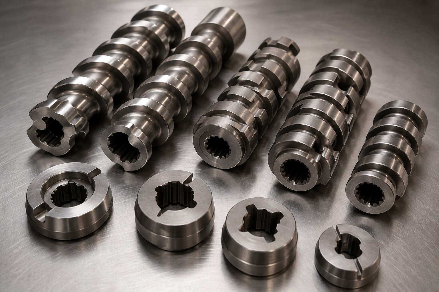
- Conveying elements (forward-pitch flights) — These are the workhorses of material transport. Deep-flighted conveying elements pull solid feedstock into the barrel at the feed zone and push melt forward toward the die. A deeper channel design provides higher screw volume for efficient conveyance without imparting significant shear or breaking down ingredients. Wider pitch increases throughput capacity; narrower pitch builds more forward pressure.
- Kneading blocks (narrow and wide disc configurations) — Kneading elements are the primary mixing workhorses. They consist of multiple lobed discs stacked at offset angles along a short segment. Wider kneading discs promote dispersive mixing — breaking down agglomerates through high shear stress — while narrower discs favor distributive mixing, spreading the dispersed phase evenly without aggressive particle size reduction. The stagger angle between discs matters too: forward-angled kneading blocks are less aggressive and maintain some conveying action, neutral (90-degree) blocks maximize energy input by halting forward flow, and reverse-angled blocks push material backward, creating maximum restriction and the highest shear intensity.
- Reverse elements (left-hand pitch) — These elements convey material opposite to the main flow direction. Their purpose isn't to move material backward permanently — it's to create localized pressure buildup and melt seals. Positioned upstream of vent ports, reverse elements prevent molten polymer from escaping through vent openings. They also extend residence time in the zones immediately preceding them, which is useful when the process needs more time for melting, mixing, or chemical reaction.
- Toothed mixing elements — These specialized elements feature rows of interlocking teeth rather than continuous flights. They generate distributive mixing without significant dispersive shear, making them ideal for blending temperature-sensitive additives or achieving homogeneity in already-melted polymer systems where further particle breakdown is unnecessary.
- Slotted distributive mixing elements — Variations on conveying elements with slots or grooves cut into the flights, these elements split and recombine the melt stream repeatedly. They enhance distributive mixing at relatively low energy input — a valuable tool when uniform colorant distribution or gentle additive incorporation is the goal.
Screw Configuration Strategy Along the Barrel Length
Individual elements only become meaningful when arranged into a deliberate sequence — a processing recipe written in metal. Here's how experienced engineers typically structure a plastic extrusion screw configuration from feed throat to die, and why each zone's element selection must align with the barrel segment beneath it.
Feed zone: Deep-flight, wide-pitch conveying elements dominate. The priority is pulling material in quickly and moving it forward without restriction. The barrel section here is usually cooled, and the screw design supports that by avoiding any elements that would generate heat through shear. Pitch in this zone commonly ranges from 2.5 to 3.5 times the screw diameter, depending on feedstock form — powders need higher volume capacity than pellets.
Melting and mixing zones: Conveying pitch tightens, and kneading blocks appear. Forward kneading elements initiate melting through viscous dissipation. As the material transitions to a fully molten state, wider kneading blocks or neutral-stagger blocks take over to deliver the dispersive and distributive mixing that breaks filler agglomerates and homogenizes multi-component formulations. The barrel segments in these zones carry the highest heating loads — and often the highest cooling demands, since shear-generated heat can push melt temperatures above target if left unchecked.
Melt seal and venting zones: A short section of reverse elements creates a fully filled, pressurized melt seal just upstream of each vent port. This seal prevents the melt from flowing backward into the vent opening. Immediately downstream, large-pitch conveying elements reduce the degree of fill, expanding the melt's free surface area so that volatiles — moisture, trapped air, residual monomers — can escape efficiently through the barrel's vent port. Without the reverse element creating a proper seal, venting fails entirely, regardless of how well the barrel's vent section is designed.
Metering zone: Shallow-pitch conveying elements compress the melt into a consistent, pressurized stream ready for die extrusion. The barrel's temperature control in this final zone maintains the melt within its processing window, while the screw elements ensure steady volumetric output that minimizes surging at the die.
Here's the critical point that ties everything back to barrel design: the screw configuration and the barrel zone layout must be planned together as a unified system. A kneading block positioned under a vent port barrel segment will block devolatilization. A side feeder barrel opening aligned with a reverse element will cause backflow and feed jamming. Every change to one side of the equation — swapping a barrel segment, adding a vent port, repositioning a side feeder — demands a corresponding check on the screw element sequence beneath it.
When problems emerge during production — incomplete melting, poor filler dispersion, excessive melt temperature, or degraded product color — experienced processors troubleshoot by adjusting the extruder screw configuration. Replacing a neutral kneading block with a forward-angled one reduces shear input. Adding a short conveying section between two kneading zones gives the material a brief thermal recovery period. Shortening a reverse element reduces backpressure and residence time. Each modification shifts the energy balance inside the barrel, and the barrel's heating and cooling zones must be re-tuned to match.
This interdependence between screw geometry and barrel environment is exactly why specifying a twin screw barrel extruder requires more than picking a screw diameter from a catalog. The real performance envelope is defined by a set of technical specifications — L/D ratio, torque density, speed range — that together determine how much processing flexibility the barrel-screw system can actually deliver.
Key Technical Specifications Every Engineer Should Evaluate
Screw element geometry and barrel segmentation define what a twin screw barrel extruder can do. Specifications define what it can do at scale — how much material it processes per hour, how much energy it delivers into the melt, and how many functional zones fit within its processing length. Yet specification sheets for twin screw extruder machines can feel like alphabet soup: L/D, OD/ID, Nm/cm³, kW, RPM. Without understanding what each number actually controls, engineers risk over-specifying expensive capacity they'll never use — or under-specifying a machine that bottlenecks production within months of installation.
This section breaks down the specifications that matter most, explains how they interact, and provides a framework for matching them to real application requirements.
L/D Ratio and What It Means for Processing Capability
The length-to-diameter ratio — universally written as L/D — is the single most important dimensional specification on any double screw extruder machine. It tells you the available processing length relative to the screw diameter. A 40:1 L/D on a 50 mm twin screw extruder, for example, means the barrel's active processing section is 2,000 mm long.
Why does this matter? Because every functional zone along the barrel — feed, melting, mixing, venting, metering — occupies a certain number of diameters. More zones require more length. And more length means a higher L/D ratio.
Industry data from Plastics Today puts the typical L/D range for high-speed energy input (HSEI) co-rotating twin screw extruders at 32:1 to 48:1, with configurations up to 60:1 possible for specialized processes. Other industry sources cite ranges extending to 68:1 for the most complex compounding operations. The right ratio depends entirely on what the process demands:
- 32:1 to 36:1 — Sufficient for straightforward tasks like simple pelletizing, color concentrate production, or single-additive blending where one mixing zone and minimal venting are adequate.
- 40:1 to 48:1 — The sweet spot for most compounding applications. This range accommodates a full melting zone, one or two intensive mixing sections, at least one vacuum vent, and a proper metering zone. Engineering plastic compounding — think glass-fiber-reinforced nylon or flame-retardant polycarbonate — typically falls here.
- 52:1 to 68:1 — Required when the process stacks multiple unit operations in series: upstream melting, mid-barrel side feeding of fillers, multiple kneading zones for staged dispersion, two or more vacuum vent sections for thorough devolatilization, and extended metering for output stability. Reactive extrusion, high-fill mineral compounding, and processes involving both liquid injection and downstream venting push into this territory.
Here's the practical trade-off: longer barrels cost more, occupy more floor space, and increase residence time — which can cause thermal degradation in heat-sensitive polymers. Shorter barrels save capital but may force compromises on mixing quality or venting capability. The L/D ratio is not a "bigger is better" specification. It's a capacity envelope that must match the number of process steps your application requires.
For early-stage development work, a laboratory twin screw extruder — typically in the 16 mm to 27 mm screw diameter range — allows engineers to test formulations and validate screw configurations at small scale before committing to production-size equipment. A lab scale extruder running at the same L/D ratio and similar OD/ID geometry as the planned production machine provides scale-up data that translates reliably to full-size systems. This is why many compounding operations maintain a laboratory extruder alongside their production lines: it's far cheaper to optimize a screw configuration on 5 kg/hr than on 500 kg/hr.
Screw Diameter, Torque, and Speed Specifications
L/D ratio tells you how long the processing section is. Screw diameter, torque, and speed tell you how much work the machine can do within that length. These three specifications are deeply interrelated — changing one shifts the balance of the other two — and together they define the twin-screw extruder machine's throughput capacity, energy input capability, and shear intensity.
| Specification | What It Measures | Why It Matters | Relationship to Barrel Selection |
|---|---|---|---|
| Screw Diameter (OD) | The outside diameter of each screw, typically ranging from 20 mm (lab scale) to 180 mm+ (high-volume production) | Production capacity scales approximately with the square of the screw diameter — doubling diameter roughly quadruples throughput potential. Diameter also determines the physical size of the barrel bore and the machine's overall footprint. | Barrel bore must be machined to extremely tight tolerances matched to the screw OD. Larger diameters require thicker barrel walls to contain higher internal pressures and accommodate more powerful heating/cooling systems. |
| Specific Torque (Md/a³) | Torque per screw shaft divided by the cube of the centerline distance between screws (expressed in Nm/cm³). This normalizes torque across different machine sizes. | Defines how much mechanical energy the drive can deliver into the process material. Higher specific torque enables processing of high-viscosity polymers, heavily filled compounds, and formulations requiring intense kneading — without exceeding the shaft's mechanical limits. | Higher torque ratings generate greater forces on the barrel bore. Barrels paired with high-torque drives must use materials and wall thicknesses engineered to withstand the increased mechanical stress without deformation or accelerated wear. |
| Maximum Screw Speed (RPM) | The highest rotational speed the drive and gearbox can deliver to the screw shafts, ranging from 300 RPM on older designs to 1,200+ RPM on modern HSEI machines | Screw speed directly controls shear rate and, combined with feed rate, determines specific throughput (kg/hr per RPM). Higher speeds increase production rate and mixing intensity but also raise melt temperature through viscous dissipation. | High-speed operation intensifies thermal cycling and abrasive wear on the barrel bore. Barrels for high-RPM machines require superior wear-resistant linings and more responsive cooling systems to manage the elevated heat generated at the screw-barrel interface. |
| OD/ID Ratio | The ratio of the screw's outside diameter to its root (inside) diameter — typically between 1.22 and 1.71 for co-rotating twin screws | A higher OD/ID ratio provides greater free volume in the screw channel, increasing conveying capacity and enabling higher throughput. A lower ratio yields deeper shaft cross-sections capable of transmitting more torque. The ratio represents a fundamental design trade-off between volume and strength. | The OD/ID ratio defines the geometry of the barrel bore's figure-eight cross-section. Barrel segments must be manufactured to match the specific OD/ID geometry of the screw set — mismatched ratios cause uneven clearances, localized wear, and processing inconsistency. |
| Motor Power (kW) | The rated power of the main drive motor, linked to torque and speed by the relationship: Power = Torque × Speed | Sets the upper limit on total energy available for the process. A useful derived metric is specific energy — kW applied divided by kg/hr throughput — which indicates how much mechanical energy each kilogram of material receives. Typical specific energy values range from 0.10 to 0.50 kW·hr/kg depending on the application. | Motor power determines the thermal load the barrel must manage. Higher power input means more viscous heat generation inside the barrel bore, demanding more aggressive cooling capacity and potentially higher-grade barrel materials to handle sustained thermal stress. |
One relationship deserves special emphasis: torque and speed are linked through the gearbox ratio. As the Plastics Today technical analysis explains, a 200 kW motor geared for 600 RPM delivers the same shaft torque as a 400 kW motor geared for 1,200 RPM. The difference is that the higher-speed configuration doubles the available RPM range — useful only if the process benefits from elevated screw speeds. If your application runs comfortably at 300 RPM, specifying a 1,200 RPM drive adds cost without adding value.
Matching Specifications to Application Requirements
A specification sheet is only useful if you know how to read it against your actual process needs. Here's a practical framework for evaluating whether a given double screw extruder's specifications match your material, throughput, and quality targets.
Start with the material. High-viscosity engineering polymers like polycarbonate demand high specific torque — the drive must deliver enough energy to plasticate and mix a resistant melt. Low-viscosity polymers like certain polyesters or waxes need less torque but may require higher screw speeds to achieve adequate mixing. Abrasive formulations shift the barrel specification toward harder linings. Chemically aggressive melts push toward corrosion-resistant barrel metallurgy.
Size by throughput. Production capacity scales roughly with the cube of screw diameter for volumetrically limited processes. A useful scale-up relationship from industry practice: Qtarget = Qreference × (ODtarget / ODreference)³. If a 27 mm laboratory twin screw extruder produces 100 kg/hr of a given formulation, a geometrically similar 75 mm production machine can theoretically approach 2,100+ kg/hr. Real-world factors — heat transfer limitations, devolatilization constraints — often reduce this, but the cube-law provides a solid starting estimate.
Define the process complexity. Count the functional zones your recipe requires: feed, melt, mix, side feed, second mix, vent, meter. Each zone consumes roughly 4 to 8 L/D. Add them up, and you have your minimum L/D requirement. If the total exceeds 48:1, you're either looking at an extended-length barrel configuration or a two-stage extrusion system.
Check the energy balance. Calculate the specific energy your process historically requires (or estimate it from similar applications). Multiply by target throughput to get required applied power. Verify the machine's motor rating, gearbox efficiency, and available torque at your expected operating RPM can deliver that power continuously without running above 80% torque — a comfortable margin that avoids tripping mechanical safety limits during normal production variability.
Verify barrel compatibility. This is the step most specification reviews skip. Confirm that the barrel's bore tolerance, lining material, cooling capacity, and segment configuration are matched to the screw set's geometry and the application's wear environment. A perfectly sized drive paired with an under-specified barrel produces a machine that hits throughput targets on day one and loses output consistency within months as the bore wears.
The specification sheet tells you what the machine was designed to do. The barrel tells you how long it will keep doing it.
Engineers evaluating twin screw extruder machines — whether for new installations, production scale-ups, or barrel replacement programs — benefit from treating these specifications not as isolated numbers but as an interconnected system. Screw diameter sets the throughput ceiling. L/D ratio sets the process complexity ceiling. Torque and speed set the energy input ceiling. And the barrel, through its material, geometry, and thermal management, determines whether the system actually reaches those ceilings reliably over thousands of operating hours.
With the technical specifications framework in place, a natural next question emerges — not about twin screw systems in isolation, but about how they compare to the simpler, lower-cost single screw alternative. For many processors, the real decision isn't which twin screw to buy, but whether a twin screw is the right architecture at all.
Twin Screw vs Single Screw Barrel Extruder Decision Framework
That question — twin screw or single screw? — is one of the highest-stakes decisions in plastics processing. It determines capital outlay, operational complexity, product quality ceiling, and long-term flexibility. Yet the answer isn't always "twin screw." Plenty of applications run beautifully on a single screw extruder at half the capital cost and a fraction of the maintenance burden. The trick is knowing which side of the line your process falls on.
What's missing from most industry discussions is a structured, honest comparison that goes beyond vague statements like "twin screw extruders offer better mixing." Better how? By how much? And at what cost? Let's break this down mechanically, then map the performance trade-offs in a format that supports real purchasing and engineering decisions.
Fundamental Mechanical Differences
A single screw extruder uses one rotating screw inside a smooth cylindrical barrel. Material moves forward primarily through drag flow — friction between the polymer and the barrel wall propels the melt toward the die. Output is pressure-dependent: change the die resistance, and the throughput shifts. There is no intermeshing geometry to create positive displacement, no self-wiping action to prevent material from stagnating in low-flow corners. Dead zones exist, particularly in the transition between screw flights and barrel wall, and residence time distribution is inherently broad.
Twin screw extruders operate on fundamentally different physics. The twin screws intermesh inside a figure-eight barrel bore, creating either the open transfer flow of co-rotating systems or the sealed C-chamber displacement of counter-rotating designs. In both cases, conveying is far less dependent on barrel wall friction. Co-rotating twin-screw extruders achieve near-positive displacement through their intermeshing geometry, while counter-rotating configurations function as true positive displacement pumps. This means output remains stable regardless of changes in melt viscosity, die pressure, or feedstock form.
The self-wiping action of intermeshing twin screws eliminates the dead zones that single screw extruders simply cannot avoid. Material cannot accumulate and degrade in stagnant pockets. Residence time distribution tightens dramatically — a critical advantage for heat-sensitive polymers and for any process where consistent thermal history determines product quality.
Feed flexibility adds another mechanical distinction. Single screw systems are typically flood-fed: the hopper stays full, and the screw's rotation speed determines feed rate. Twin screw extruders are usually starve-fed using a separate loss-in-weight feeder, which decouples feed rate from screw speed. This independence lets engineers adjust screw RPM for mixing intensity without changing throughput — a degree of process control that simply doesn't exist in most single screw setups.
Performance and Application Trade-Offs
Mechanical differences translate directly into measurable performance gaps — and equally measurable cost differences. The table below maps twin screw extruders against single screw systems across the criteria that engineers and procurement teams evaluate most frequently.
| Criteria | Twin Screw Barrel Extruder | Single Screw Barrel Extruder |
|---|---|---|
| Distributive Mixing Quality | Excellent — modular kneading blocks and specialized mixing elements provide precise control over blend homogeneity | Low to moderate — relies on shear between screw flight and barrel wall; supplemental mixing sections (e.g., Maddock, Saxton) can improve but not match twin screw capability |
| Dispersive Mixing Quality | Excellent — high shear fields at intermeshing zone and kneading blocks break agglomerates effectively | Limited — insufficient shear for breaking down hard filler agglomerates or achieving fine-phase morphology in polymer blends |
| Feed Flexibility | Wide — handles pellets, powders, flakes, regrind, and fibers through starve-fed operation | Narrow — flood-fed operation strongly favors uniform pellets; powders and irregularly shaped feedstocks cause inconsistent feeding |
| Throughput Consistency | High — near-positive displacement conveying maintains stable output despite viscosity or pressure fluctuations | Moderate — output is pressure-dependent and varies with melt viscosity changes |
| Process Flexibility and Recipe Changes | Very high — modular screw elements and barrel segments allow rapid reconfiguration for different formulations | Low — screw geometry is typically fixed; changing the processing recipe often requires a new screw |
| Material Residence Time Control | Precise — starve feeding, modular element design, and adjustable screw speed provide tight residence time distribution | Broad — drag-flow mechanism produces wider residence time distribution with limited control |
| Capital Cost | Higher — typically 2 to 3 times the cost of a comparable single screw system | Lower — simpler mechanical design with fewer precision components reduces upfront investment |
| Operating Cost | Moderate to high — higher energy input per kilogram for intensive mixing; offset by higher throughput rates in compounding applications | Lower — less shear energy input per kilogram for simple melting and conveying tasks |
| Maintenance Complexity | Higher — modular screw elements, segmented barrels, and tighter clearances require more skilled maintenance and more frequent inspections | Lower — single screw and one-piece barrel designs are mechanically simpler with longer intervals between service |
| Barrel Wear Rates | Higher — intense intermeshing action, high screw speeds, and abrasive compound formulations accelerate bore wear | Lower — drag-flow conveying produces less aggressive barrel wall contact under comparable conditions |
| Self-Wiping / Dead Zone Elimination | Excellent — intermeshing geometry continuously sweeps all surfaces, preventing material stagnation and degradation | None — dead zones exist at flight-barrel transitions; prone to material hangup and thermal degradation streaks |
| Best-Fit Applications | Polymer compounding, masterbatch production, reactive extrusion, devolatilization, nanocomposites, recycling with contaminant removal, multi-component formulations | Simple melting and conveying of pre-compounded pellets, single-resin profile extrusion, film and sheet extrusion from uniform feedstock, pipe extrusion of non-filled polymers |
Look at the capital cost row carefully. Twin screw extruders command a significant premium — and that premium is justified only when the process genuinely requires the mixing, flexibility, or feed handling capabilities that screw extruders with twin screws deliver. Paying double or triple for a machine and then running it on a simple single-material pellet-to-profile application wastes capital that could be invested elsewhere.
When a Single Screw Extruder Is the Better Choice
Balanced decision-making requires acknowledging where twin screw extruders are not the right answer. Several common processing scenarios genuinely favor the simpler, less expensive single screw platform:
- Pre-compounded pellet processing. When the material arrives as a fully formulated, pre-mixed pellet — already containing all pigments, stabilizers, and fillers in proper dispersion — the extruder's only job is to melt, convey, and pressurize. A single screw does this efficiently with lower energy consumption and simpler operation. Film lines, sheet lines, and blow molding extruders running pre-compounded resin rarely benefit from twin screw mixing capability.
- Single-resin profile and pipe extrusion. Window profiles, siding, and non-filled pipe applications require stable melt conveying and consistent pressure at the die — not intensive mixing. Single screw extruders, especially when paired with barrier-flight screw designs, deliver precisely the stable melt stream these applications need at a fraction of the twin screw cost.
- Budget-constrained operations with simple material requirements. For processors running one or two straightforward formulations at moderate volumes, the lower capital cost, simpler maintenance, and reduced operator skill requirements of a single screw system translate into a meaningfully better return on investment. The additional capability of twin screws goes unused — and unused capability is simply wasted money.
- High-volume, continuous production of single materials. Dedicated extrusion lines that run the same resin 24/7 — think commodity PE film or PP strapping — benefit from the single screw's mechanical simplicity and long maintenance intervals. Process flexibility isn't needed when the process never changes.
Choose twin screw when mixing intensity, feed flexibility, or multi-component formulations drive your process requirements. Choose single screw when simplicity, lower capital cost, and single-material processing define your operation.
The decision framework above applies to the machine architecture. But even after choosing the twin screw platform, the real engineering work — and the real performance differentiation — happens at the barrel configuration level. Which barrel zones, materials, and port layouts best match the specific application you're targeting? A compounding line processing glass-fiber-reinforced nylon demands a radically different barrel setup than a recycling line pelletizing contaminated post-consumer waste. Mapping those application-specific barrel configurations is where general knowledge becomes actionable engineering guidance.
Barrel Configuration Guide Mapped to Processing Applications
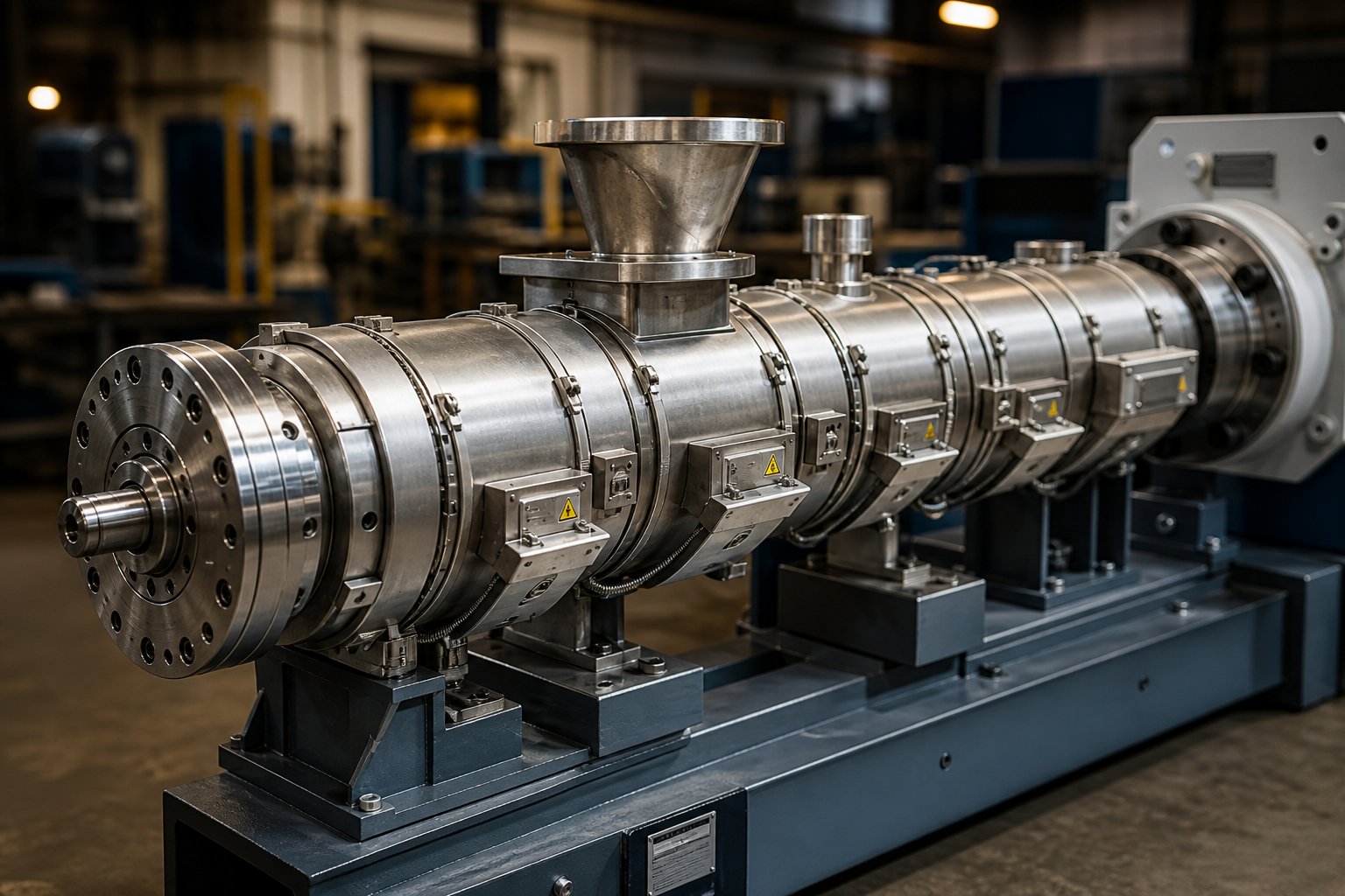
Every processing application places a different set of demands on the barrel — different thermal loads, different wear profiles, different port requirements. A compounding twin screw extruder running 40% glass-fiber-reinforced nylon needs a radically different barrel layout than a recycling line processing contaminated post-consumer flake. Yet most equipment guides treat barrel configuration as an afterthought, offering generic zone diagrams that ignore the real-world variables driving barrel selection.
This section maps common processing applications directly to recommended barrel configurations — zone counts, port placements, material specifications, and screw element strategies. Think of it as a practical blueprint you can reference when specifying a new line, reconfiguring a modular barrel, or evaluating whether your current setup truly matches the job you're asking it to do.
Polymer Compounding and Masterbatch Production
Compounding is the application that pushes every barrel specification to its limits simultaneously. A twin screw compounding extruder must melt a base polymer, incorporate one or more fillers or additives at precise loadings, achieve thorough dispersive and distributive mixing, remove moisture and volatiles, and deliver a homogeneous melt at stable pressure to the pelletizing die — all within a single barrel length.
High L/D ratios — typically 40:1 to 48:1, extending to 52:1 or beyond for complex formulations — are standard. The extra processing length accommodates multiple kneading zones for staged mixing intensity, side feeder ports for downstream filler addition, and vacuum vent sections positioned near the discharge end for moisture and volatile removal. A standard compounding barrel assembly, as described in Haisi Extrusion's technical overview, typically follows this sequence: feed barrel at zone 1, several closed barrels for melting and initial mixing, a side-feeding barrel at zone 4 or 5 for downstream filler introduction, additional closed barrels for further mixing, a vacuum degassing section near the end, and a final closed barrel before the die head.
Barrel material requirements escalate sharply when abrasive fillers enter the picture. Glass fiber, calcium carbonate, talc, and mineral fillers grind relentlessly against the barrel bore — especially at side feeder zones and downstream kneading sections where filler concentration in the melt is highest. Iron-based bimetallic linings are the minimum specification for moderate filler loadings (20% to 30%), while tungsten carbide or powder metallurgy liners become cost-justified at higher loadings or in continuous 24/7 production environments. For processors sourcing custom or replacement barrels engineered for these high-wear compounding conditions, NANHAIYA's parallel twin screw barrel offers configurations designed specifically for compounding and masterbatch operations where abrasion resistance and bore dimensional stability are critical.
Masterbatch production follows similar barrel logic but adds an additional emphasis on dispersive mixing for pigment and additive concentrate applications. A twin screw plastic extruder running color masterbatch may require wider kneading blocks or multiple kneading zones to achieve the particle fineness needed for thin film or fiber applications — as Leistritz's technical analysis notes, highly dispersive mixing applications run at comparatively lower throughput rates because the material needs more time in zones where shear effects and extensional flow fields are dominant.
Recycling and Pelletizing Operations
Recycling applications impose a unique challenge: the feedstock itself is unpredictable. Post-consumer and post-industrial waste streams arrive with variable contamination levels, inconsistent moisture content, mixed polymer fractions, and degraded molecular weight. The barrel configuration must accommodate this variability without sacrificing output quality or accelerating component wear.
Multiple venting zones are the defining feature of recycling barrel layouts. Contaminated feedstock releases moisture, volatile organic compounds, residual inks, adhesive residues, and decomposition byproducts during melting. A single vent port is rarely sufficient. Most recycling configurations include at least two vent sections — one atmospheric vent early in the barrel for initial moisture flash-off, and one or two vacuum vent ports downstream for deeper devolatilization. As noted in Leistritz's devolatilization guidance, vent efficiency depends on surface area renewal and residence time under the vent — factors controlled by screw speed and degree of fill in those zones.
Gentle metering sections are equally important. Recycled polymers have already undergone one or more thermal processing cycles, which means their molecular chains are partially degraded. Aggressive kneading in the metering zone pushes melt temperature higher and accelerates further degradation. Experienced processors use forward-pitch conveying elements and mild mixing geometries in the final barrel sections to preserve whatever molecular weight remains.
For a screw extruder granulator setup in a recycling plant, barrel material selection must account for the hard contaminants commonly found in recycled streams — metal fragments, sand, glass particles, and paper fiber residue. Bimetallic barrel linings rated for abrasive service extend bore life significantly compared to standard nitrided steel. Replacement barrels for recycling lines — such as those available from NANHAIYA's parallel twin screw barrel program — are often specified with enhanced wear resistance to handle the unpredictable abrasive loads that recycled feedstocks introduce.
Reactive and Specialty Extrusion Applications
Reactive extrusion transforms the twin screw barrel extruder from a mixing device into a continuous chemical reactor. Applications include grafting reactions, controlled degradation (vis-breaking), polymer chain extension, and in-situ polymerization. What sets reactive configurations apart is the barrel's role in managing chemistry, not just thermomechanical processing.
Liquid injection ports become essential. Peroxides, silane coupling agents, chain extenders, and reactive monomers must be introduced at precisely controlled locations along the barrel — typically into a partially filled melt section where mixing elements immediately downstream incorporate the liquid before the reaction advances. The barrel's temperature zone control takes on heightened importance because reaction kinetics are temperature-sensitive: a 10°C deviation in the wrong zone can shift conversion rates, molecular weight distribution, or grafting efficiency outside acceptable limits.
A polyester extruder running reactive chain extension, for example, requires tight thermal control across at least six to eight independent heating and cooling zones to maintain the narrow processing window that prevents hydrolytic degradation while allowing the chain extension reaction to proceed. The barrel segments in the reaction zone often run with intensified cooling to counteract the exothermic heat generated by the chemical reaction itself.
Food and pharmaceutical extrusion applications shift the balance in the opposite direction — toward gentle processing. A plastic twin screw extruder configured for food-grade starch cooking or pharmaceutical hot-melt extrusion uses conveying-dominant screw profiles with minimal kneading intensity. Barrel materials switch from wear-focused bimetallic linings to 316L stainless steel for regulatory compliance and cleanability. Lower screw speeds, reduced L/D ratios (often 25:1 to 36:1), and precisely managed barrel temperatures protect thermally and shear-sensitive ingredients from degradation.
The table below consolidates these application-specific recommendations into a single reference, mapping each processing application to its recommended barrel configuration parameters.
| Application Type | Recommended L/D Ratio | Typical Number of Zones | Key Barrel Features | Barrel Material Recommendation | Critical Screw Element Arrangement |
|---|---|---|---|---|---|
| Polymer Compounding (unfilled or lightly filled) | 40:1 to 48:1 | 8 to 10 | 1 side feeder port, 1 vacuum vent, optional atmospheric vent | Nitrided steel or iron-based bimetallic for moderate wear | Wide kneading blocks in primary mixing zone; narrow kneading for distributive blending; reverse elements before vent |
| High-Fill Compounding (glass fiber, mineral fillers >20%) | 44:1 to 52:1 | 10 to 12 | 1-2 side feeder ports for downstream filler addition, 1-2 vacuum vents, back-venting option at feed | Iron-based bimetallic (minimum); tungsten carbide or powder metallurgy liners for highest filler loads | Forward narrow kneading blocks after side feeder for gentle fiber incorporation; reverse kneading for melt seal upstream of vacuum vent |
| Masterbatch / Color Concentrate | 40:1 to 48:1 | 8 to 10 | 1 atmospheric vent, optional vacuum vent for moisture-sensitive carriers | Iron-based bimetallic for pigment abrasion resistance | Multiple kneading zones with wide discs for dispersive pigment breakdown; neutral kneading blocks for maximum shear intensity |
| Recycling and Pelletizing (post-consumer / post-industrial) | 40:1 to 48:1 | 8 to 12 | 2-3 vent ports (atmospheric + vacuum) for contaminant removal; optional side feeder for additive dosing | Iron-based bimetallic for abrasive contaminant resistance | Extended melting zone with moderate kneading; gentle forward-pitch metering zone to minimize thermal degradation; reverse elements for melt seals at each vent |
| Reactive Extrusion (grafting, chain extension, vis-breaking) | 44:1 to 56:1 | 10 to 14 | 1-2 liquid injection ports, 1-2 vacuum vents for byproduct removal, 6-8+ independent temperature zones | Nickel-based bimetallic or powder alloy for corrosive reaction byproducts | Medium kneading intensity at injection zone for rapid liquid incorporation; extended conveying zones for controlled residence time; reverse elements for melt seal before vent |
| Food / Pharmaceutical Extrusion | 25:1 to 36:1 | 5 to 8 | Liquid injection port for plasticizers or active ingredients; atmospheric vent for steam release | 316L stainless steel for regulatory compliance and cleanability | Conveying-dominant profile with minimal kneading; narrow forward kneading blocks only where gentle mixing is needed; no reverse elements to avoid excessive residence time |
| Twin Screw Extruder Plastic Pelletizing (virgin resin) | 32:1 to 40:1 | 6 to 8 | 1 atmospheric vent, optional vacuum vent; simple die-face or strand pelletizing discharge | Nitrided steel for standard polymers; bimetallic for engineering plastics | Standard conveying and moderate kneading for homogenization; shallow-pitch metering elements for stable die pressure |
Notice how each application demands a different combination of barrel length, port placement, lining metallurgy, and screw element strategy. A compounding extruder running high-fill glass fiber needs bimetallic linings and downstream side feeders. A recycling line needs multiple vent ports and gentle metering. A reactive extrusion setup needs liquid injection and intensified temperature control. No single barrel configuration serves all of these — which is precisely why modular barrel systems and application-matched replacement barrels deliver such high return on investment.
What all these configurations share, however, is vulnerability to the same enemy: wear. Regardless of how perfectly a barrel is specified at installation, every hour of production erodes the bore surface, widens clearances, and gradually degrades the processing precision that the entire system depends on. Understanding how that wear happens — and when to act on it — is what separates processors who maintain consistent quality from those chasing quality drift they can't explain.
Barrel Wear Mechanisms, Monitoring, and Maintenance Best Practices
Every barrel specification discussed so far — the bimetallic linings, the modular segmentation, the precise bore tolerances — exists to serve one purpose: keeping the gap between screw flight and barrel wall within the narrow dimensional window that makes consistent processing possible. The moment that gap widens beyond specification, everything downstream suffers. Output drops. Melt temperature rises. Product quality drifts. And unless you understand why the bore is wearing and how fast, the problem compounds silently until it forces an unplanned shutdown.
Barrel wear is not a question of if — it's a question of which mechanism, how quickly, and what to do about it. For any twin screw and barrel system running in production, proactive wear management is the difference between scheduled maintenance and emergency downtime.
Understanding Barrel Wear Mechanisms
Three distinct mechanisms attack the barrel bore surface during operation. Each leaves a different signature, progresses at a different rate, and demands a different prevention strategy. Knowing which one dominates your process is the first step toward controlling it.
Abrasive wear. This is the most common form of wear in twin screw extruders, and it's driven by hard particles grinding against the barrel bore. Glass fibers, calcium carbonate, talc, silica, titanium dioxide, and contaminants in recycled feedstock all act as abrasive agents. As Xtrutech's wear analysis notes, abrasive wear is dependent on the amount of material produced rather than simply the hours the extruder has been running. The sharp machined edges of screw elements and barrel bore surfaces gradually become rounded, smooth, and occasionally polished. The rate depends on filler hardness, particle size, filler loading percentage, and the velocity at which material passes over metal surfaces — which means kneading zones and side feeder entry points experience the most aggressive abrasion.
Corrosive wear. Chemical reactions between the processing material and the barrel's metal surface cause the bore to pit, dimple, or develop surface irregularities. Acidic polymers like PVC release hydrochloric acid during thermal processing. Fluoropolymers generate hydrofluoric acid. Flame retardant additives, certain colorant chemistries, and decomposition byproducts from degraded recycled materials all contribute corrosive attack. Even condensation on internally cooled barrel sections can trigger localized corrosion if moisture contacts the bore surface at elevated temperatures. Corrosive wear is insidious because it often proceeds beneath the surface before becoming visible — by the time pitting appears during a visual inspection, the bore has already lost significant dimensional integrity.
Adhesive wear. This happens when metal contacts metal directly. In a twin screw barrel extruder, the plastic extruder screw flights are supported by the molten polymer flowing through the barrel during production. When the screws rotate without adequate melt support — during startup, shutdown, or idle periods at high speed — the shafts deflect and the flight tips contact the barrel wall. The result, as Xtrutech describes, is flattened screw flight outer diameters and score marks on the barrel bore. If the twin screws deflect and contact each other, scratches appear on the tips, flanks, and roots of the screw flights. Adhesive wear is the most preventable of the three mechanisms — controlled startup and shutdown procedures that maintain material in the barrel during screw rotation eliminate most metal-to-metal contact events.
In practice, most extruder screw and barrel systems experience a combination of all three mechanisms, with one dominating depending on the material and operating conditions. Recognizing the early warning signs before wear reaches a critical threshold is essential for planning maintenance rather than reacting to failures.
- Declining output consistency — Throughput begins fluctuating at constant screw speed because material leaks backward over worn flight tips instead of conveying forward.
- Increasing melt temperature at constant screw speed — As Plastics Technology's analysis explains, worn clearances reduce the heat-transfer coefficient at the barrel wall while requiring higher screw speeds to maintain rate, both of which push discharge temperature upward.
- Visible wear marks on removed screws — Rounded flight tips, polished surfaces in kneading zones, and scoring on flight flanks all indicate corresponding barrel bore deterioration.
- Rising specific energy consumption — The extruder draws more power per kilogram of output because a larger proportion of screw energy dissipates as heat through widened clearances rather than doing useful work on the material.
- Product quality variations — Inconsistent color dispersion, undispersed filler agglomerates, gel particles, or fluctuating mechanical properties in finished products all point toward degraded mixing uniformity caused by bore wear.
Barrel Lifespan Factors and Monitoring Approaches
How long does a barrel actually last? There's no universal answer because barrel lifespan is the product of multiple interacting variables — not a fixed number you can read from a catalog. The dominant factors include:
Material abrasiveness. A barrel running unfilled polypropylene may last five to ten times longer than one compounding 40% glass-fiber-reinforced nylon at the same throughput. Filler hardness, particle angularity, and concentration are the strongest predictors of abrasive wear rate.
Filler loading percentage. Wear accelerates nonlinearly with filler content. Going from 20% to 40% glass fiber does not simply double the wear rate — it may triple or quadruple it because the higher filler concentration increases the frequency of abrasive particle contact with the barrel bore.
Barrel material and lining quality. A nitrided steel barrel running an abrasive compound may last a fraction of the time a properly matched bimetallic or tungsten carbide-lined barrel would. The lining selection discussion from earlier in this article directly determines how many production hours the bore surface can withstand before tolerances fall out of specification.
Operating temperatures. Elevated barrel temperatures soften most metallic surfaces slightly, reducing their hardness and accelerating wear. Uneven heating caused by faulty barrel heaters can also warp the barrel, as Plastics Technology notes, causing thermal distortion that forces the screw against the bore wall in localized areas.
Screw-to-barrel clearance maintenance. Running a worn screw inside a new barrel — or vice versa — creates uneven clearance distribution that accelerates wear on the newer component. Both elements of the extruder screw and barrel system should be evaluated together, not independently.
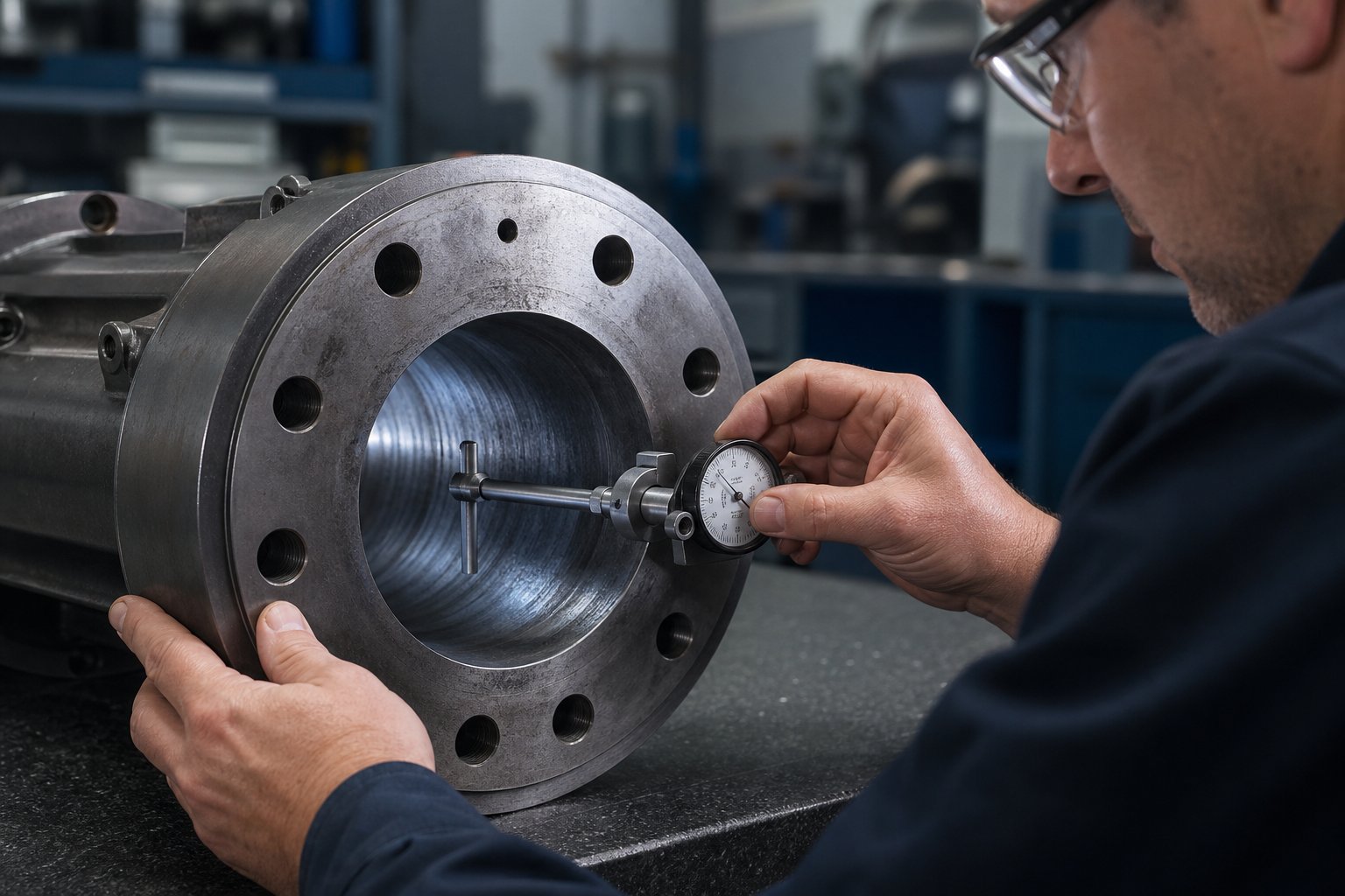
Bore measurement is the primary monitoring tool. Using precision bore gauges or specialized measurement instruments inserted through the barrel bore, technicians measure the internal diameter at multiple points along the barrel length. Industry guidelines from Xtrutech suggest that barrel liners should be considered for replacement when the bore diameter has increased by approximately 5% from its starting dimension over a length of one screw diameter. For screw elements, the corresponding guideline is approximately 5% reduction from the starting outer diameter over three-quarters of the element length. Monthly visual inspection of the barrel bore — particularly in kneading zones and downstream of side feeders where wear concentrates — catches degradation early enough to order replacement components before damage cascades.
A useful benchmark from Plastics Technology's engineering data: a barrel with an iron-based bimetallic liner typically lasts approximately three times the service life of a screw running under the same conditions. This asymmetry makes sense — the screw flights bear the brunt of direct abrasive contact, and their smaller cross-section wears faster than the larger barrel bore surface. It also means screw replacement frequency becomes a useful indirect indicator of barrel condition: if you've replaced screws three times without measuring the barrel, the bore is almost certainly out of tolerance.
Replacement and Refurbishment Best Practices
When bore measurements confirm that wear has reached the action threshold, processors face a decision: refurbish the existing barrel or replace it entirely? The right answer depends on the severity of wear, the barrel's construction, and the economics of your specific operation.
Refurbishment options include re-boring the barrel to a larger internal diameter and fitting oversized screw elements to match, or re-lining a worn barrel with a new bimetallic or alloy liner. Refurbishment typically costs less than a new barrel and can be completed faster — a compelling advantage when production schedules are tight. However, refurbishment has limits. Each re-boring operation removes wall thickness, reducing the barrel's pressure containment capability and thermal mass. A barrel can generally be refurbished only once or twice before the remaining wall thickness falls below the minimum required for safe operation.
Full replacement is the better long-term investment when wear is severe, when the original barrel material was under-specified for the application, or when the cost difference between refurbishment and replacement is small relative to the expected additional service life. Replacing a worn nitrided steel barrel with a properly matched bimetallic-lined replacement, for instance, may cost more upfront but deliver three to five times the service life — making it the lower cost-per-operating-hour option by a wide margin. The same economic logic from Plastics Technology's guidance applies: the decision should be driven by the economics of the process, weighing the cost of the new or refurbished component against the production losses from reduced rate and quality.
One critical caution from industry practice: a screw should never be refurbished more than three times. Each re-application of hard facing welds new material onto a base that has been thermally cycled repeatedly, increasing the risk of delamination between the hard facing and the base metal. The same principle applies to barrel liners — repeated refurbishment degrades the metallurgical bond between the liner and the barrel body.
Regardless of whether you refurbish or replace, one principle is non-negotiable: the replacement barrel's metallurgy must match the specific wear environment of your application. A recycling line chewing through contaminated post-consumer feedstock needs a different lining than a food-grade extruder running clean starch formulations. Sourcing a generic barrel because it fits the machine dimensions — without verifying that its material composition matches your wear profile — is a shortcut that leads to premature failure and another unplanned replacement cycle.
Keeping a spare barrel segment or complete barrel assembly in stock eliminates extended downtime during replacement. When the production barrel reaches the end of its service life, the spare goes in during a scheduled maintenance window, and the worn barrel goes out for refurbishment or recycling. This extruder technology best practice — maintaining a rotating inventory of critical wear components — keeps the line running while worn parts are serviced offline.
Wear management, bore monitoring, and replacement planning are the operational disciplines that protect the investment you've made in barrel materials, modular segmentation, and application-specific configurations. But they're reactive by nature — they respond to wear that has already occurred. The final piece of the puzzle is proactive: knowing how to select and source the right barrel from the outset so that every specification decision, from metallurgy to segment layout, is matched to the application before the first pellet hits the feed throat.
How to Select and Source the Right Twin Screw Barrel
Understanding barrel wear, material options, and modular configurations is valuable — but only if that knowledge translates into better purchasing decisions. Engineers who can recite the differences between iron-based and nickel-based bimetallic linings still end up with under-performing barrels when the sourcing process itself lacks structure. The gap between technical knowledge and procurement execution is where most barrel selection mistakes happen.
With the twin screw extruders market projected to account for 55.0% of extruder and compounding machine revenue in 2026, the pool of twin screw extruder manufacturers and barrel suppliers has expanded significantly — especially across Asia-Pacific markets where China alone holds over a third of global plastics production capacity. More options mean more opportunities, but also more risk of selecting a supplier whose metallurgical capability doesn't match the promises on their website. A systematic approach eliminates that risk.
Building Your Twin Screw Barrel Specification Checklist
Before contacting a single supplier, you need a complete specification document that captures every parameter your barrel must satisfy. Skipping this step — or leaving it incomplete — is how procurement teams end up comparing quotes on barrels that aren't actually equivalent. Follow these steps in sequence:
- Identify your application and material requirements. Document the polymer being processed, filler types and loading percentages, chemical additives, and any corrosive byproducts (HCl from PVC, HF from fluoropolymers). Include the full range of formulations the barrel will encounter — not just the primary product. A barrel specified for unfilled polypropylene will fail prematurely if your production schedule occasionally includes 30% glass-fiber-reinforced nylon.
- Determine the required L/D ratio and screw diameter. Count the functional zones your process demands — feed, melting, mixing, side feeding, venting, metering — and allocate 4 to 8 L/D per zone. The total sets your minimum barrel length. Screw diameter follows from your throughput target using the cube-law scaling relationship discussed in the specifications section. If you're replacing an existing barrel, match the original dimensions unless process changes justify a configuration upgrade.
- Specify barrel material and lining based on the wear environment. Use the wear mechanism analysis from earlier: abrasive-dominant applications need iron-based bimetallic or tungsten carbide linings, corrosive environments require nickel-based alloys, and food-grade operations call for 316L stainless steel. Document the expected dominant wear mechanism and any secondary threats. This single specification decision has the largest impact on service life and total cost of ownership.
- Define needed barrel features — vent ports, side feeders, injection points. Map out exactly which barrel segments require open ports and which must remain closed. Specify atmospheric versus vacuum vent configurations. Note any liquid injection requirements and the port diameter and thread standard needed. For modular barrels, document the segment sequence so suppliers quote the correct combination of segment types.
- Establish torque and speed requirements. The barrel must withstand the mechanical loads generated by the drive system. Higher specific torque ratings and elevated screw speeds generate greater forces on the barrel bore and increased thermal cycling. Confirm that the barrel wall thickness, material grade, and cooling capacity are rated for the machine's maximum operating parameters — not just the current production settings.
- Evaluate supplier capabilities for custom configurations. If your application requires non-standard segment layouts, specialized port placements, or unusual lining combinations, verify that potential suppliers can deliver custom configurations with the same quality assurance applied to their standard catalog items. Custom barrels are only as good as the supplier's engineering and manufacturing depth.
This checklist becomes your Request for Quotation (RFQ) foundation. When every supplier receives the same detailed specification, their quotes become genuinely comparable — and the differences in twin screw extruder price reflect real capability gaps rather than specification ambiguity.
Evaluating Barrel Suppliers and Manufacturers
A specification document tells suppliers what you need. Evaluating suppliers tells you who can actually deliver it. Not all twin-screw extruder manufacturer operations that offer barrels possess the same depth of metallurgical expertise, quality control rigor, or production capability. The criteria below separate specialist barrel manufacturers from resellers who simply broker components from third-party foundries.
- Metallurgical expertise and material traceability. Can the supplier explain why they recommend a specific lining alloy for your application — not just which one? Reliable twin screw extruder manufacturers provide material certificates (EN 10204 3.1 or equivalent) documenting the alloy chemistry, hardness values, and heat treatment parameters for every barrel they ship. Suppliers who cannot produce these documents on request are likely sourcing barrels from uncertified subcontractors.
- Custom segmented barrel configuration capability. Modular barrel systems require precision machining of individual segments, accurate alignment of cooling bores and heater pockets across segment joints, and consistent bore tolerance from first segment to last. Ask for dimensional inspection records showing bore concentricity and surface finish across assembled multi-segment barrels. This is where manufacturing depth separates specialists from assemblers.
- Quality control processes for bore tolerance and surface finish. Bore tolerance in twin screw barrels is measured in hundredths of a millimeter. Suppliers should demonstrate CMM (coordinate measuring machine) inspection capability or equivalent precision measurement, with documented acceptance criteria for bore diameter, roundness, and surface roughness. Request sample inspection reports from recent production runs.
- Production lead times and inventory management. A barrel that takes 16 weeks to deliver when your production line is down for wear creates enormous opportunity cost. Evaluate whether the supplier stocks standard barrel segments for common machine platforms or manufactures everything to order. Suppliers with consignment stock programs or regional warehousing reduce your exposure to extended downtime during unplanned replacements.
- After-sale technical support. The best barrel suppliers don't disappear after shipment. They provide installation guidance, bore measurement protocols, wear monitoring recommendations, and troubleshooting support when barrel-related processing issues arise. This ongoing relationship becomes especially valuable when you're evaluating whether a worn barrel should be refurbished or replaced — a decision that requires the supplier's metallurgical judgment, not just a sales quote.
- Application-specific experience. A supplier experienced in barrels for compounding glass-fiber-reinforced engineering plastics may not have equivalent expertise in barrels for food-grade extrusion or reactive processing. Match the supplier's documented application history to your specific processing environment.
For processors exploring their barrel sourcing options, NANHAIYA's parallel twin screw barrel program offers a practical starting point — particularly for compounding producers, masterbatch manufacturers, recycling plants, and pelletizing operations sourcing replacement or custom barrels designed for high-wear plastic processing applications. Their product page provides configuration details relevant to processors evaluating barrel options across these application categories.
Beyond individual suppliers, consider how your evaluation fits the broader market context. The extruder and compounding machines market is projected to grow from USD 82.3 billion in 2026 to USD 124.2 billion by 2036, with supplier pricing increasingly reflecting barrel metallurgy and wear control as key value differentiators. In a twin screw extruders market moving up the materials curve — where over half of new installations specify bimetallic barrel construction — procurement teams still buying commodity nitrided assemblies risk running equipment that no longer matches the polymers being processed inside it.
The cheapest barrel to purchase is almost never the cheapest barrel to operate. Specify based on total cost of ownership, not purchase price.
Whether you're sourcing a twin screw extruder for sale evaluation, requesting replacement barrel quotes, or specifying a complete barrel-screw system for a new production line, the framework above ensures every decision — from material selection to supplier qualification — is anchored in application-specific engineering rather than catalog shopping. The barrel may not be the most visible component of your extrusion line, but as every section of this article has demonstrated, it's the one that determines how long, how consistently, and how profitably the entire system runs.
Twin Screw Barrel Extruder FAQs
1. What is the difference between co-rotating and counter-rotating twin screw extruders?
Co-rotating twin screw extruders have both screws turning in the same direction, producing a figure-eight flow pattern with excellent self-wiping action and high mixing intensity — ideal for compounding and reactive extrusion. Counter-rotating extruders spin screws in opposite directions, creating sealed C-shaped chambers that generate high pressure with lower shear, making them the standard choice for PVC pipe and profile extrusion. Counter-rotating designs also come in parallel and conical geometries, with conical variants offering a compact footprint and natural compression for medium-capacity lines.
2. How do I choose the right barrel material for a twin screw extruder?
Barrel material selection depends on three factors: the abrasiveness of your fillers, the chemical aggressiveness of the melt, and your production volume. Nitrided steel suits general-purpose unfilled polymers. Iron-based bimetallic linings handle glass fiber and mineral fillers at moderate to heavy loadings. Nickel-based alloys resist corrosive attack from PVC, fluoropolymers, and flame retardants. Tungsten carbide coatings serve extreme abrasion in high-fill or continuous production. For food or pharmaceutical applications, 316L stainless steel meets regulatory and cleanability standards. Suppliers like NANHAIYA offer parallel twin screw barrels with application-matched linings for compounding, recycling, and pelletizing operations.
3. What does L/D ratio mean on a twin screw extruder and how do I select it?
L/D ratio is the barrel's active processing length divided by the screw diameter. It determines how many functional zones — feeding, melting, mixing, venting, and metering — fit within the barrel. Ratios of 32:1 to 36:1 handle simple pelletizing. Most compounding applications need 40:1 to 48:1 for adequate mixing and venting. Complex processes involving multiple side feeders, reactive injection, and multi-stage devolatilization may require 52:1 to 68:1. Longer barrels add cost and residence time, so the goal is matching L/D to the exact number of process steps your formulation requires.
4. When should I replace a twin screw extruder barrel instead of refurbishing it?
Replace rather than refurbish when bore wear is severe, when the original barrel material was under-specified for the application, or when the remaining wall thickness after re-boring would fall below safe pressure containment limits. A barrel can typically be refurbished only once or twice before walls become too thin. Full replacement with a properly matched bimetallic lining often costs more upfront but delivers three to five times the service life, making it the lower cost-per-operating-hour choice. Always match the replacement barrel's metallurgy to your specific wear profile — abrasive, corrosive, or adhesive — rather than choosing a generic fit.
5. What are the main advantages of a modular segmented barrel design?
Modular barrel segmentation lets processors reconfigure a single twin screw extruder for multiple products by rearranging individual barrel sections. Each segment can incorporate side feeder openings, atmospheric or vacuum vent ports, liquid injection ports, or remain fully closed. This reduces capital expenditure because one machine platform serves many recipes. It also cuts maintenance costs — when a single high-wear segment degrades, only that piece needs replacement rather than the entire barrel assembly. The key is designing the segment layout in concert with the screw element configuration so that vent ports, melt seals, and feeder openings align correctly.
Written by
Nanhaiya Technical Team
Zhoushan Nanhaiya Plastic Machinery Co., Ltd.
The Nanhaiya technical team supports screw and barrel manufacturing projects through application review, technical communication, custom manufacturing coordination, and production and quality control.
Discuss Your Application
Related Articles
More insights on screw barrel technology and plastics processing.

Extruder Machine Decoded: From Raw Pellet To Finished Product
Oct 6, 2026
Learn how an extruder machine works, compare single-screw vs. twin-screw types, and get expert guidance on specs, troubleshooting, and selection.
Read Article
PE Pipe Making Machine Decoded: From Raw Resin to Flawless Pipe
Oct 4, 2026
Learn how a PE pipe making machine works, from resin to finished pipe. Covers components, material grades, automation, troubleshooting, and buyer selection tips.
Read Article
PVC Profile Making Machine Decoded: From Raw Resin To Profit
Oct 3, 2026
Learn how a PVC profile making machine works — extrusion process steps, key technical parameters, die design, calibration methods, maintenance, and total cost of ownership.
Read ArticleLooking for something else?
Search by material, symptom or product and jump straight to the relevant page.
These are navigation suggestions based on keyword matching — not a quotation, not a delivery commitment, and not a substitute for engineering review. Final specification is confirmed by our engineers against your drawings and processed material.
Need help with screw barrel selection?
Share your machine model, processed material and application. Our team can help with pricing and technical support.