

Understanding the Twin Screw and Barrel as a Unified System
Imagine two helical screws spinning in precise synchronization inside a barrel machined to tolerances measured in hundredths of a millimeter. That interaction — metal against polymer against metal — determines whether you produce premium compound or costly scrap. Yet most technical resources treat the screw and the barrel as separate topics, leaving engineers to piece together the full picture on their own.
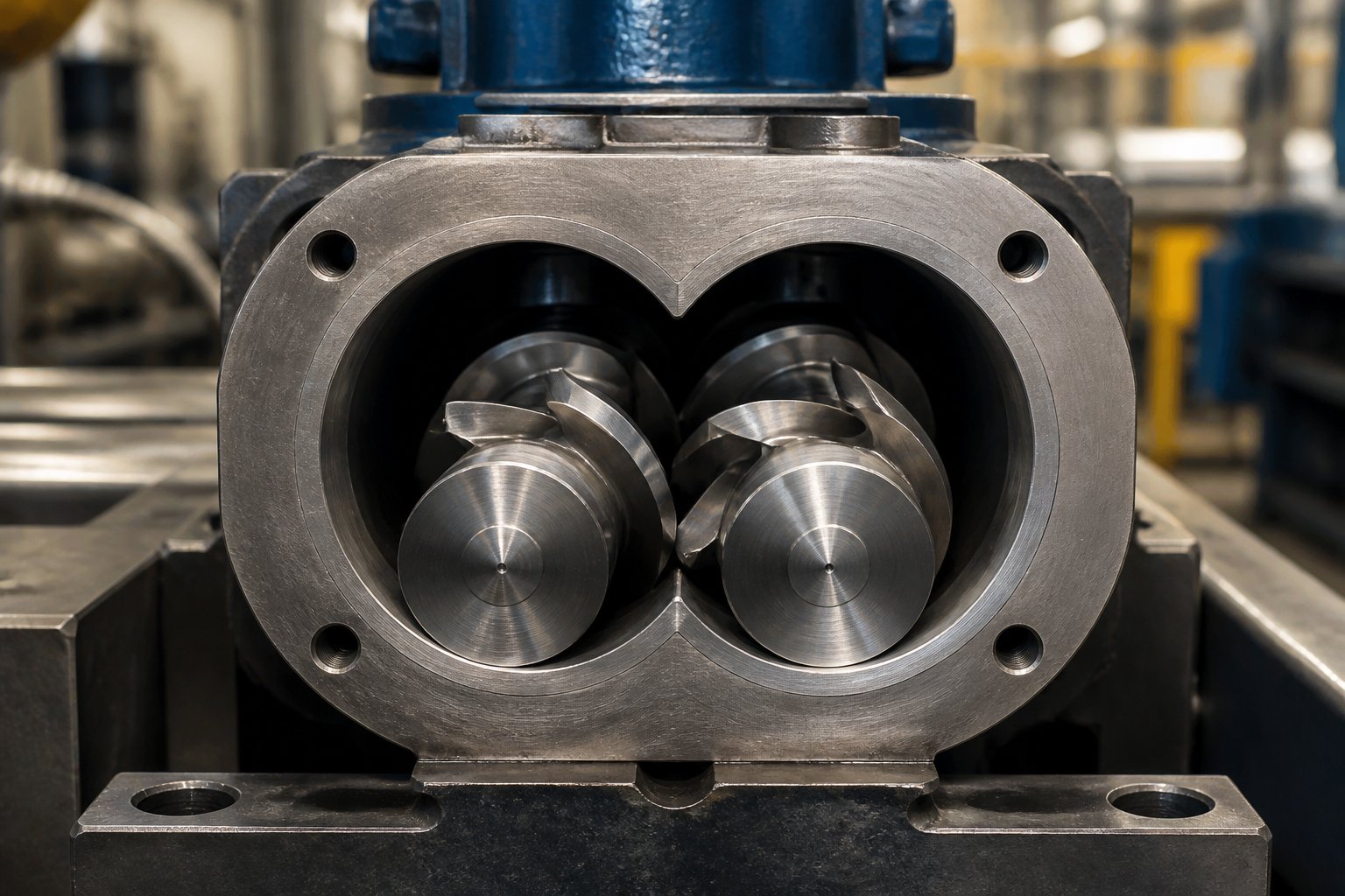
A twin screw and barrel system consists of two intermeshing screws — either co-rotating or counter-rotating — housed within a figure-eight bore barrel. Working together, these components convey, melt, mix, and shape polymers and compounds in a continuous, highly controllable process used across compounding, pelletizing, recycling, and masterbatch production.
That definition captures the hardware, but it only hints at why the system view matters so much. This article goes deeper — covering screw element types, barrel section functions, metallurgy and liner technology, polymer-to-configuration matching, temperature zone management, wear lifecycle planning, and a practical selection framework you can apply to your next project.
What Is a Twin Screw and Barrel System
At its core, every twin screw barrel configuration relies on the synergy between screw geometry and barrel construction. The screws do not simply push material forward. Depending on their element design, they can build pressure, generate intense shear, distribute additives, or create back-pressure zones — all within a single machine. The barrel, meanwhile, provides structural containment, thermal management through independently controlled heating and cooling zones, and strategically placed openings for feeding, venting, or side-stuffing additives.
Whether a facility runs a co-rotating setup for high-shear compounding or a counter-rotating configuration for gentle PVC processing, the twin screw extruder's performance hinges on how well its two halves — the rotating elements and the stationary barrel — complement each other.
Why the Screw-Barrel Relationship Matters
Here is what many overlook: screw element selection directly drives barrel wear patterns. A high-intensity kneading block concentrates shear energy on a specific barrel zone, accelerating abrasion right at that point. Flip the equation, and barrel metallurgy constrains which screw configurations are practical — a nitrided steel liner simply cannot withstand the same glass-fiber loads that a tungsten carbide liner handles routinely.
Treating extruder screws and barrels as independent purchasing decisions often leads to mismatched wear rates, unexpected downtime, and inflated cost of ownership. The sections that follow approach both components as a single engineered system, giving you the technical depth to make coordinated decisions — from element sequencing and liner chemistry all the way through to maintenance scheduling and supplier evaluation.
Screw Element Types and Their Roles in Processing
Every extruder screw profile is essentially a recipe — a carefully ordered sequence of individual elements, each contributing a specific function to the overall process. Change one element and you shift shear intensity, residence time, or melt temperature in ways that ripple through the entire barrel. Understanding what each element does, and where it belongs along the screw, is the foundation of effective twin screw and barrel design.
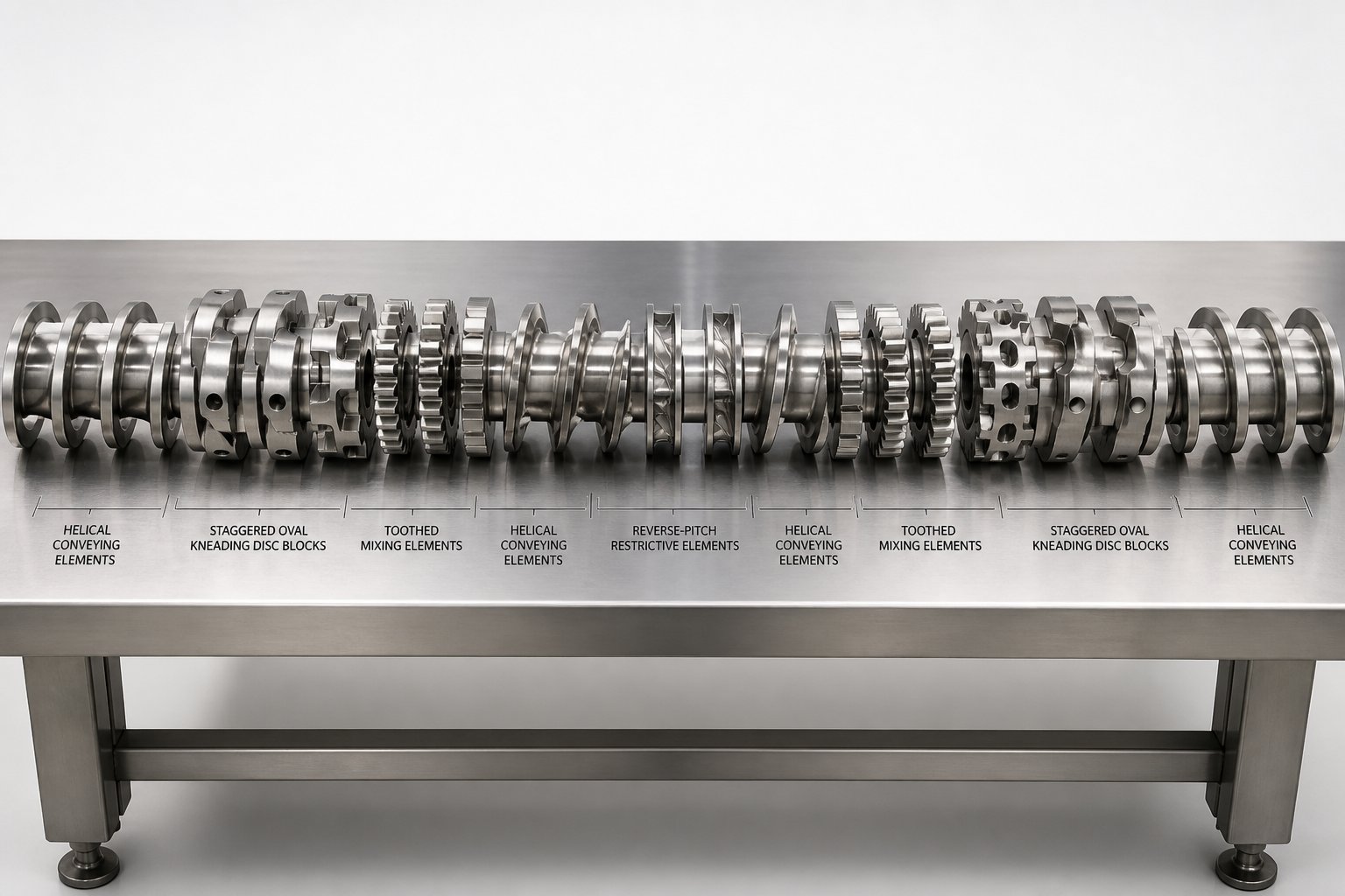
Four major element categories make up the vast majority of profiles used in twin screw compounding, pelletizing, and masterbatch production. They typically appear along the screw shaft in this order:
- Conveying elements — helical flights that transport material forward, with varying pitch to control feed rate and pressure.
- Kneading blocks — staggered disc arrangements that deliver high-shear dispersive and distributive mixing to melt and homogenize polymers.
- Mixing elements — toothed, gear, or turbine-type geometries that distribute additives with lower shear intensity than kneading blocks.
- Restrictive (barrier) elements — reverse-pitch flights or reverse kneading blocks that create back-pressure, increase fill level, and extend residence time.
Each category serves a distinct purpose, yet their real power emerges from how they interact within a single screw configuration. Let's break them down.
Conveying and Kneading Elements Explained
Conveying elements are the workhorses of solids transport. Their deep-flighted, helical geometry moves pellets, powders, or already-molten polymer downstream without imparting significant shear. You'll notice these elements at the feed throat — where a large-pitch design maximizes volumetric intake — and again after kneading zones, where a tighter pitch rebuilds pressure and pushes the melt toward the next processing section. As NC State Extension research explains, conveying capability decreases as pitch decreases, giving engineers a simple lever for fine-tuning pressure profiles along the barrel.
Kneading blocks are where the real transformation happens. A kneading block consists of a series of oval discs, each offset from the previous one by a specific stagger angle. That angle is the single most important variable controlling shear intensity:
- 30° stagger — gentle forward conveying with moderate mixing. Ideal as a transition element at the entrance to a melt zone, easing material from conveying flights into higher-shear regions.
- 60° stagger — strong energy input with reduced forward pumping. This is the primary workhorse for melting crystalline polymers and dispersing agglomerates.
- 90° stagger — a neutral element that imparts maximum shear without pushing material forward. It acts as a melt dam, increasing local fill and ensuring complete melting before the polymer advances.
Disc width matters just as much as angle. Industry analysis from Plastics Technology highlights that wider discs force more polymer over the tip of each paddle and through the narrow gap between disc and barrel wall — the highest-shear zone in the entire extruder. Narrower discs slice through the melt more gently, favoring distributive mixing over heat generation. By combining different stagger angles and disc widths within a single kneading section, a plastic extruder screw profile can be tuned from mild to aggressive without swapping hardware elsewhere in the machine.
Reverse kneading blocks deserve special mention. Flipping the stagger direction so discs rotate counterclockwise (on a right-handed screw) pumps material upstream, creating an intense restriction. This is the most severe melting element available and is typically reserved for high-melt-point engineering plastics or crystalline polymers that resist melting under milder conditions.
Mixing and Restrictive Elements for Process Control
Imagine you've already melted the polymer and need to blend in a color concentrate or distribute a liquid additive uniformly — without driving melt temperature any higher. That's where mixing elements shine. Toothed mixing elements (sometimes called ZME or TME types) use rows of interlocking teeth rather than continuous discs to split and recombine the melt stream repeatedly. The result is excellent distributive mixing with near-zero dispersive shear, preserving sensitive additives, pigment particles, or fiber lengths that kneading blocks would damage.
Gear-type and turbine-style mixing elements follow a similar philosophy. They redirect melt flow across multiple channels, promoting homogeneity through division and recombination rather than brute-force shearing. Engineers typically position these extruder screws elements downstream of the melt zone — after kneading is complete — to polish the blend before it reaches the die.
Restrictive elements occupy the opposite end of the intensity spectrum. A reverse-pitch conveying element, for instance, actively pushes material backward, generating a pressure seal that increases fill level and residence time upstream. This pressure seal serves several purposes: it ensures complete melting before material passes the restriction, it creates the melt seal necessary for effective downstream venting, and it increases back-mixing for improved homogeneity. The length of a restrictive element is typically kept shorter than the screw diameter to avoid excessive pressure spikes and localized overheating.
When would an engineer choose a restrictive element over a reverse kneading block? Restrictive conveying elements generate a harder seal and higher localized pressure, making them the go-to for vacuum venting sections where any melt leakage past the seal would compromise devolatilization. Reverse kneading blocks provide a softer restriction with more mixing action, making them better suited to the end of a melting section where gentle back-mixing improves melt quality without creating dangerous pressure peaks.
How Element Sequencing Affects Barrel Wear
Here is the detail that connects screw design directly to barrel longevity: every high-shear element concentrates mechanical energy and abrasive contact at a specific point along the barrel bore. A cluster of 60° and 90° kneading blocks generates intense heat and particle-to-wall friction in the barrel zone directly surrounding it. If the compound includes mineral fillers or glass fibers, that friction becomes aggressively abrasive — accelerating wear on the barrel liner at precisely those locations.
This means element placement is not just a process variable; it is a direct input to barrel liner selection. A barrel zone aligned with conveying elements may survive for years with a standard nitrided liner, while the adjacent zone housing kneading blocks might demand a tungsten carbide or bimetallic liner to achieve the same service life. Ignoring this relationship leads to uneven wear — some barrel sections degrade far faster than others, forcing premature shutdowns and costly partial replacements.
The interplay doesn't stop at abrasion. Corrosive off-gassing from certain polymers tends to concentrate near venting and compression zones, adding a chemical attack vector on top of mechanical wear. Mapping each extruder screw element to the barrel section it occupies — and selecting liner metallurgy accordingly — is one of the most cost-effective engineering decisions in the entire extrusion line. That metallurgical dimension is exactly where the discussion turns next.
Barrel Section Types and How They Shape Extrusion Performance
Screw elements define what happens to the polymer — but the barrel defines where and under what conditions those events occur. Every extruder barrel is not a single monolithic tube. In a twin screw system, it is a modular assembly of individual segments, each engineered for a distinct role in the process chain. Rearrange those segments and you fundamentally change the machine's capability, all without cutting metal or ordering a new barrel from scratch.
Four primary barrel section types form the building blocks of virtually every twin screw layout. The table below summarizes their functions, typical placement, and defining design features.
| Section Type | Primary Function | Typical Position Along Barrel | Key Design Feature |
|---|---|---|---|
| Feed barrel | Accepts raw material into the extruder | Barrel 1 (first position); occasionally Barrel 2 for back-vent configurations | Top opening sized for pellets or powders; often hardened or grooved liner for improved material intake |
| Closed barrel | Maintains pressure and temperature for melting, mixing, and pumping | Multiple positions between feed and discharge | Full 360-degree enclosure around the figure-eight bore; independent heating and cooling on all sides |
| Venting section | Removes moisture, volatiles, and trapped air from the melt | Upstream of the die (vacuum vent); adjacent to feed or side-feed zones (atmospheric vent) | Open port or vacuum connection on top of barrel; may include vent stuffers for foaming compounds |
| Side-feed section | Introduces fillers, fibers, or additives downstream into the melt stream | Mid-barrel, typically at Barrel 4 or 5 on a 40:1 L/D machine | Secondary figure-eight bore on the barrel side for a twin-screw side stuffer; often paired with an upstream atmospheric vent |
Each section type is typically four to six screw diameters long, independently heated, and — in modern designs — internally cooled through liquid channels. That modularity is what makes the twin screw extruder barrel uniquely flexible compared to single-screw systems, where adding a vent or feed point means modifying or replacing an entire one-piece barrel.
Feed Barrel and Venting Section Functions
The extruder feed barrel is the gateway to the entire process. Pellets, free-flowing granules, or powders drop through a top opening directly onto the rotating screws. To maximize material intake — especially for low-bulk-density powders — some feed barrels feature grooved or hardened liners that increase friction between the incoming material and the barrel wall, preventing the powder from simply spinning with the screws without advancing forward.
Sounds straightforward? It gets more nuanced with powders. Lightweight powders carry entrained air that resists being pulled down into the screws. A common solution, detailed by Plastics Technology, is a back-vent arrangement: the powder feeds into Barrel 2 while Barrel 1 remains open, giving the displaced air a clear escape path upstream. Without that relief, air backs up into the feed throat and chokes throughput.
Venting sections serve the opposite purpose — they let gases out rather than solids in. During compounding, polymers release moisture, volatile additives, or decomposition byproducts that must be extracted before the melt reaches the die. Atmospheric vents handle moderate gas volumes near feed zones and side stuffers, while vacuum vents positioned close to the discharge end pull residual volatiles under negative pressure. For hygroscopic polymers like nylon, or for recycled streams loaded with contaminants, effective venting is not optional — it is the difference between saleable pellets and porous, foaming scrap.
The placement of each vent deserves careful thought. Positioning a vacuum vent two barrel sections upstream of the die, rather than immediately before it, provides a pressure buffer that prevents molten polymer from backing up into the vent opening when head pressure fluctuates during a production run.
Closed Barrel and Side-Feed Section Design
Closed barrel sections are the most numerous segments in any extruder barrel assembly, and for good reason. They fully enclose the figure-eight bore on all four sides, providing maximum surface area for heating and cooling while maintaining the pressure needed for melting and intensive mixing. When kneading blocks or restrictive elements generate high localized pressures, the closed barrel section contains those forces and transfers heat in or out through its independently controlled thermal zones.
Side-feed sections add a second dimension of flexibility. Picture a scenario where you need to load 40% glass fiber into a PA6 melt. Feeding all that fiber at the main throat would expose it to the full melting and kneading sequence, shattering fibers into dust. Instead, a side-feed barrel positioned downstream allows the fiber to enter an already-molten polymer stream, preserving fiber length while achieving thorough wetting. The side stuffer — a small co-rotating twin-screw auger — pushes the additive directly into the barrel extruder through a secondary figure-eight bore machined into the side of the segment.
A more compact design, sometimes called a back-vent combi-barrel, combines the side-feed port with a small upstream atmospheric vent in a single barrel segment. This arrangement lets entrained air escape while fillers are being stuffed in — a critical detail when processing high volumes of low-bulk-density minerals like calcium carbonate or talc.
How Barrel Section Arrangement Drives Process Outcomes
Here is the point many engineers underestimate: barrel layout is not permanent. Because each segment bolts to the next, an extruder barrel can be reconfigured to match different formulations or process goals. Need to add a second vacuum vent for a high-volatile recycled resin? Swap a closed barrel for a vented one and adjust the screw profile underneath. Switching from a single-filler compound to a dual-additive formulation? Insert an additional side-feed section at a downstream position.
The key constraint is coordination. The sequence of feed, closed, vent, and side-feed extruder barrels must align with the screw element profile beneath them. A vent barrel is useless unless the screw elements directly upstream create a filled melt seal that prevents polymer from flowing backward out of the vent port. Similarly, a side-feed section works only if the screw elements in that zone are partially starved — meaning the channels are not completely full — so there is room for the incoming additive.
This interplay between barrel architecture and screw geometry is what makes twin screw extrusion so powerful — and so unforgiving when the two are mismatched. The same modular principle extends to barrel bore geometry itself, where the choice between parallel and conical configurations opens an entirely different set of trade-offs in torque, compression, and application fit.
Parallel vs. Conical Twin Screw Barrel Comparison
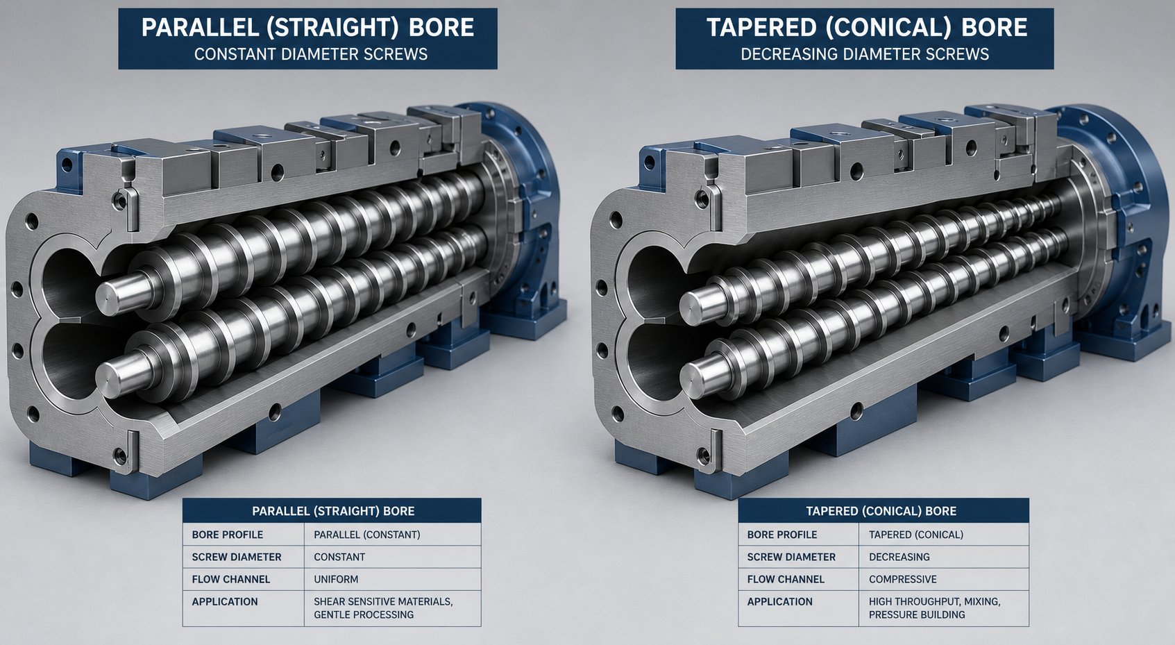
The modular barrel sections covered above all share one assumption: the bore is a straight, constant-diameter figure-eight from feed to discharge. That describes a parallel twin screw extruder — but it is not the only option. Conical twin screw extruders taper their bore (and screws) from a large-diameter feed end to a smaller discharge end, fundamentally changing how compression, torque, and shear behave along the machine. Choosing between these two geometries is one of the earliest — and most consequential — decisions in any extrusion project.
The table below puts the key differences side by side so you can compare at a glance.
| Dimension | Parallel Twin Screw Barrel | Conical Twin Screw Barrel |
|---|---|---|
| Bore geometry | Straight figure-eight bore; constant screw diameter along full length | Tapered figure-eight bore; screw diameter decreases from feed to discharge |
| L/D ratio range | 32:1 to 52:1 (and beyond with barrel extensions) | Typically 20:1 to 28:1; limited by taper geometry |
| Typical screw diameter range | 20 mm to 180+ mm | 35/70 mm to 80/156 mm (small end/large end) |
| Throughput capacity | High; scalable by extending barrel length or increasing screw speed | Moderate; output increases require larger taper diameters, not length |
| Shear characteristics | Tunable via modular screw elements; wide range from gentle to intensive | Progressive compression built into taper; less element-level tunability |
| Primary applications | Compounding, masterbatch, filled compounds, reactive extrusion, recycling | PVC pipe, PVC profile, PVC sheet, WPC (wood-plastic composite) |
| Relative cost | Higher initial investment (complex gearbox, modular elements) | Lower entry cost for dedicated PVC lines |
Those numbers tell part of the story. The engineering logic behind each geometry reveals why certain applications gravitate toward one configuration over the other.
Parallel Twin Screw Barrel Geometry and Advantages
A parallel twin screw extruder houses two screws of identical, constant diameter along their entire length inside a straight figure-eight bore. Most parallel machines run in a co-rotating configuration — both screws turn in the same direction — which produces an "infinity-pattern" material flow that delivers outstanding self-wiping behavior and intensive mixing. This is the design you'll encounter most often in compounding, pelletizing, and masterbatch operations worldwide.
Several advantages make the co rotating twin screw extruder the dominant platform for formulation-intensive work:
- Modular screw and barrel design. Individual conveying, kneading, mixing, and restrictive elements slide onto splined shafts, allowing rapid profile changes between production runs. The barrel segments are equally interchangeable, as described in the previous section.
- Higher L/D ratios. Because the bore diameter stays constant, barrels can be extended simply by adding more segments. Ratios of 40:1 to 52:1 are common, and some machines stretch beyond 60:1 for complex devolatilization or reactive extrusion tasks.
- Superior mixing flexibility. The ability to place kneading blocks, gear mixers, and restrictive elements at any point along the screw gives engineers fine-grained control over shear intensity, residence time, and melt temperature — critical when switching between unfilled polymers and highly loaded mineral or fiber compounds.
- Easier output scaling. Need more throughput? Stretching pitches on conveying elements or increasing screw speed delivers higher output without changing the barrel bore — a flexibility that Rollepaal's engineering comparison highlights as a key advantage over conical designs, where output increases typically require a physically larger taper diameter.
- Wider processing window. Parallel designs offer more freedom to adjust gelation, venting position, and pressure generation independently, reducing the risk of over-fusion or air inclusions — particularly relevant for PVC applications where conical machines can present narrow operating margins.
Historically, the gearbox was a weak point for parallel machines. Two output shafts sitting at a small center-to-center distance left limited room for bearings and gears, constraining torque capacity. Modern finite-element-optimized gearboxes have largely closed that gap. Today's parallel systems deliver torque densities from 5 Nm/cm³ on entry-level models to over 12 Nm/cm³ on premium platforms — sufficient for virtually all thermoplastic compounding and reactive extrusion scenarios.
Conical Twin Screw Barrel Geometry and Use Cases
Picture two screws that start wide at the feed end and taper down to a noticeably smaller diameter at the discharge. That converging geometry is the defining feature of a conical twin screw extruder, and it produces a natural compression effect — the decreasing channel volume forces material into progressively tighter space without requiring specialized barrier elements on the screw.
Most conical machines use a counter-rotating arrangement: the two tapered screws turn in opposite directions, conveying material forward in roughly closed "C"-shaped chambers. This design provides several practical benefits:
- High torque transmission at the feed end. Because the large end of the taper allows generous center-to-center distance between shafts, the gearbox can accommodate bigger bearings and sturdier gears. That translates into robust torque capacity without the engineering complexity that parallel gearboxes face.
- Compact footprint. The shorter L/D ratio (typically 20:1 to 28:1) and converging bore geometry produce a machine that occupies significantly less floor space than a parallel extruder of comparable throughput.
- Gentle, positive-displacement conveying. Counter-rotating intermeshing screws create near-sealed conveying chambers, minimizing back-flow and providing precise residence-time control — ideal for heat-sensitive materials like PVC dry blends, where excessive shear or prolonged heat exposure causes degradation.
- Built-in compression ratio. The taper itself acts as a compression device, generating the pressure needed for die feeding without relying heavily on restrictive screw elements. This simplifies screw design and reduces localized hot spots.
These strengths explain why the conical twin screw extruder dominates PVC pipe and profile production. PVC's narrow thermal processing window — the gap between adequate gelation and thermal degradation — demands gentle, controlled energy input, and the conical geometry delivers exactly that. Wood-plastic composite (WPC) extrusion also benefits from the strong feed-end torque that handles high-bulk-density wood-flour blends effectively.
The trade-off? Flexibility. Conical screws are typically one-piece designs, not modular. Changing the screw profile means replacing the entire screw set rather than rearranging individual elements. And because extending barrel length requires increasing the large-end diameter (not just adding segments), scaling output on a conical machine is mechanically more involved than on a parallel system.
Choosing Between Parallel and Conical Configurations
So which geometry fits your operation? The decision usually narrows down to two questions: what material are you processing, and how much formulation flexibility do you need?
Choose a parallel twin screw extruder when:
- You compound multiple polymer families (PP, PE, PA, PC, TPE) and need to switch formulations frequently.
- Your recipes include high filler loadings (calcium carbonate, talc, glass fiber) that demand tailored screw element profiles for each compound.
- Throughput targets require high L/D ratios, elevated screw speeds, or downstream devolatilization stages.
- You run masterbatch, reactive extrusion, or recycled-stream operations where modular barrel reconfiguration adds significant value.
Choose a conical twin screw extruder when:
- Your production is dedicated to PVC profiles, PVC pipes, or WPC lines with limited formulation variation.
- Compression ratio and feed-end torque are primary design priorities.
- Floor space is constrained and a shorter machine length is advantageous.
- Lower capital investment matters and the application does not require frequent screw-profile changes.
One common source of confusion: the term "double screw extruder" is frequently applied to both parallel and conical machines in product listings and trade catalogs. If you are evaluating a double screw extruder machine, always verify the actual bore geometry — parallel or conical — before comparing specifications, because the throughput capacity, shear behavior, and modularity differ fundamentally between the two. A double screw extruder machine labeled simply as "twin screw" could be either type, and assumptions based on the name alone can lead to costly mismatches.
For the majority of compounding and masterbatch applications, the parallel co-rotating configuration has become the industry default — its modular twin screw and barrel architecture, broad L/D range, and mixing versatility outweigh the higher initial investment for operations that process diverse formulations. Conical systems remain the proven, cost-effective choice for dedicated PVC and WPC processing lines where their natural compression and torque advantages align perfectly with the material's demands.
Regardless of which geometry you select, the barrel liner must withstand the specific combination of abrasion, corrosion, and thermal stress that your polymer and filler package imposes. That metallurgical dimension — the liner materials and technologies that protect the barrel bore — is where the next layer of engineering decisions begins.
Barrel Metallurgy and Liner Technology Demystified
The bore surface of an extrusion barrel takes a relentless beating. Every revolution of the screws drives abrasive filler particles, corrosive polymer off-gases, and superheated melt against the inner wall at pressures that can exceed 200 bar in kneading zones. How long that bore maintains its dimensional integrity — and therefore how long your screw and barrel system produces consistent output — depends almost entirely on one factor: the metallurgy of the liner.
Four primary liner technologies dominate modern extrusion barrels. Each offers a different combination of hardness, abrasion resistance, corrosion resistance, and cost. The table below provides a snapshot you can use as a quick-reference when evaluating barrel specifications.
| Liner Type | Hardness (HRC Range) | Abrasion Resistance | Corrosion Resistance | Best Application Match | Relative Cost |
|---|---|---|---|---|---|
| Nitrided steel | 65-70 HRC (surface) | Moderate | Moderate | Unfilled commodity polymers (PE, PP, PS) | 1.0x (baseline) |
| Bimetallic - Iron-based (Fe-Cr-B) | 58-62 HRC | High | Moderate | Moderately filled compounds (CaCO3, talc, mid-fiber) | 1.8-2.5x |
| Bimetallic - Nickel-based (Ni-Cr-B-W) | 60-65 HRC | High | High | PVC, CPVC, halogenated flame retardants | 2.0-3.0x |
| Tungsten carbide (WC-rich or HVOF WC) | 65-75 HRC | Very high | Moderate to high | Glass-fiber-filled engineering plastics, mineral-reinforced compounds | 3.0-5.0x |
| Powder metallurgic steel (CPM 10V/15V) | 60-64 HRC | Very high | Low to moderate | High-abrasion + impact-loading applications (mineral-filled HDPE, WPC) | 4.0-6.0x |
Those numbers tell you what each liner can handle in theory. The sections below explain how each one is made, where it excels, and where it falls short — so you can match the right metallurgy to your actual process conditions.
Nitrided Steel and Bimetallic Barrel Liners
Nitrided barrels represent the baseline option for extrusion barrels. The manufacturing process is straightforward: a single-piece barrel machined from nitriding-grade alloy steel — most commonly 38CrMoAlA, EN-41B, or Nitralloy 135M — is placed in a gas or plasma nitriding furnace at 500-550 degrees Celsius. Nitrogen atoms diffuse into the bore surface, creating a hardened case with surface hardness in the range of 950-1,100 HV (roughly 65-70 HRC equivalent).
The critical limitation? That hardened case is only 0.4 to 0.6 mm deep. Beneath it, the core steel retains its original toughness at around 280-320 HB — far too soft to resist abrasive wear. Once filler particles penetrate past that thin shell, wear accelerates rapidly and the barrel needs replacement. There is no second chance with a nitrided bore.
For unfilled or lightly filled commodity polymers — virgin PE, PP, PS — that shallow case is perfectly adequate. A well-manufactured nitrided barrel processing clean polyolefins can deliver five to ten years of reliable service at roughly half the capital cost of bimetallic alternatives. Over-specifying bimetallic for these applications wastes money with no operational benefit.
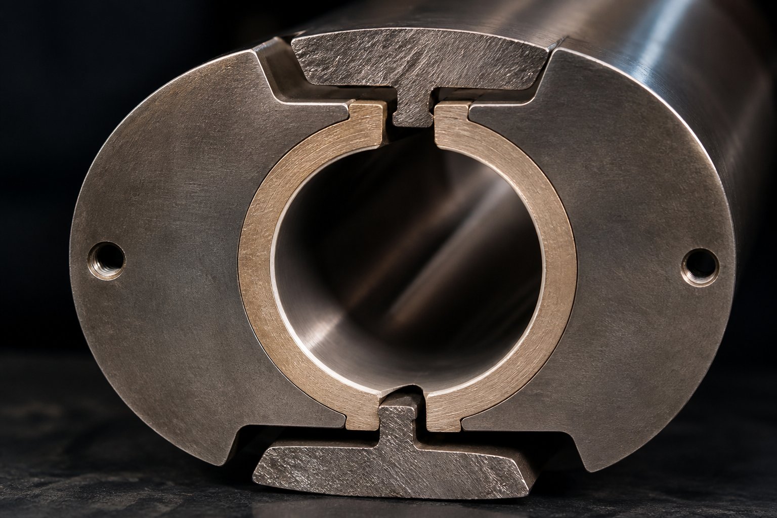
Bimetallic liners take an entirely different approach. Instead of hardening the surface of a single steel, the manufacturer centrifugally casts a wear-resistant alloy inside a structural steel shell. The barrel rotates at controlled speed while molten alloy is introduced at approximately 1,100 degrees Celsius, producing a metallurgical bond between the outer shell and a liner that is typically 1.5 to 3.0 mm thick — roughly five to six times the effective wear depth of a nitrided bore.
Two alloy families dominate bimetallic construction. Iron-based liners (Fe-Cr-B compositions with chromium, boron, and tungsten carbides in an iron matrix) reach 58-62 HRC and handle general abrasive service well — think calcium carbonate at 20-40% loading, talc-filled polypropylene, or mid-range fiber compounds. Nickel-based liners (Ni-Cr-B-W compositions) push hardness to 60-65 HRC while adding a critical advantage: corrosion resistance. When you process PVC, CPVC, or halogenated flame retardant compounds, hydrogen chloride gas forms at processing temperatures and attacks unprotected steel aggressively. Nickel-based alloys form passive surface films that resist that chemical attack, making them the standard extrusion screw barrel pairing for any chlorinated polymer line.
The cost premium for bimetallic construction typically runs 1.8x to 3.0x compared to nitrided, depending on alloy grade and barrel diameter. Yet field data consistently shows bimetallic liners lasting two to three times longer in moderate-wear service and three to seven times longer in severe-wear applications — making them the lower total-cost-of-ownership choice for any compound containing significant filler, fiber, or corrosive chemistry.
Tungsten Carbide and Powder Metallurgic Steel Options
When glass fiber at 30% or above enters the equation, even standard bimetallic liners face accelerated wear. Glass fiber acts as a continuous abrasive jet against the bore, with a Mohs hardness of 5.5 to 6.5 — hard enough to erode iron-based alloys at commercially unacceptable rates. This is where tungsten carbide liners earn their premium.
Tungsten carbide (WC-rich) liners embed extremely hard carbide particles within a nickel or cobalt matrix, reaching bore hardness of 65-75 HRC. HVOF (high-velocity oxygen fuel) thermal spray coatings push even higher, with coating hardness of 1,100 to 1,400 HV and porosity below 1%. In production environments processing 30% or more glass-fiber-reinforced PA66 or PBT, WC-rich bimetallic barrels routinely deliver service lives three to five times longer than standard iron-based bimetallic alternatives. For any glass-fiber compounding line, the question is not whether to specify tungsten carbide — it is which WC alloy grade and liner thickness to select.
One nuance worth noting: when the process combines abrasion with corrosion — such as glass-fiber-filled compounds containing halogenated flame retardants — the cobalt binder in conventional WC-Co liners becomes a vulnerability. Cobalt dissolves in HCl-rich environments. Substituting a nickel-chromium binder (WC-CrC-Ni or WC-CrC-NiCr compositions) reduces corrosion current density by five to eight times while maintaining hardness above 1,000 HV, according to published tribology research.
Powder metallurgic (PM) steels occupy a different niche. Grades like CPM 10V (2.45% C, 5.25% Cr, 9.75% V) are manufactured through a particle metallurgy process that produces an exceptionally uniform distribution of vanadium carbides — each individual carbide particle reaching approximately 2,500 HV hardness. Unlike conventionally cast tool steels, where carbide segregation creates weak zones, PM steels deliver consistent wear resistance throughout the cross-section.
What sets PM steels apart from tungsten carbide liners is toughness. WC coatings are brittle; they resist abrasion superbly but can crack under impact loading or substrate deflection on high-L/D barrels. PM steels combine high hardness (60-64 HRC) with significantly greater fracture resistance, making them the preferred choice for demanding applications where abrasion meets mechanical impact — such as mineral-filled HDPE processing or wood-plastic composite extrusion, where large, irregular particles create both sliding abrasion and repeated impact forces against the bore.
Matching Liner Selection to Process Demands
With four liner options on the table, how do you choose? The decision flows directly from your compound's dominant wear mechanism.
- Unfilled or lightly pigmented polymers (PE, PP, PS, ABS): Nitrided steel. The thin hardened case handles adhesive and mild abrasive wear at the lowest capital cost. Bimetallic is over-engineered for these applications.
- Moderately filled compounds (CaCO3 at 20-40%, talc, mica): Iron-based bimetallic. The 1.5-3.0 mm liner depth provides the wear reserve that nitrided bores cannot sustain under continuous filler abrasion.
- Corrosive polymer systems (PVC, CPVC, halogenated FR compounds): Nickel-based bimetallic. Corrosion resistance is non-negotiable here — nitrided 38CrMoAlA corrodes at rates of 0.08 to 0.15 mm per 1,000 operating hours in PVC service, while nickel-based alloys cut that rate by a factor of five or more.
- Glass-fiber-filled engineering plastics (PA, PBT, PC at 30%+ GF): Tungsten carbide or WC-rich bimetallic. Nothing else survives the abrasive intensity of continuous glass-fiber contact at acceptable service intervals.
- High-abrasion plus impact-loading applications (mineral-filled HDPE, WPC): Powder metallurgic steel (CPM 10V or CPM 15V). The combination of high hardness and superior toughness handles both wear modes simultaneously.
One practical detail that engineers frequently overlook: liner selection must be coordinated with screw element materials for balanced wear. Running a premium tungsten carbide barrel with a standard nitrided screw creates a hardness mismatch that accelerates screw wear while the barrel remains nearly pristine. The result is premature screw replacement and uneven clearance growth across the extrusion screw barrel assembly. Best practice calls for maintaining a hardness differential of two to four HRC between the screw and barrel surfaces — with the barrel slightly harder to protect the more expensive, less easily replaced component.
That coordinated approach extends beyond metallurgy alone. Different polymer families impose different combinations of abrasion, corrosion, and thermal stress — and each combination calls for a specific pairing of barrel liner, screw material, and machine configuration. Mapping those pairings systematically across major polymer types is the natural next step toward a fully integrated specification.
Matching Twin Screw and Barrel Configurations to Polymer Types
Barrel metallurgy protects the bore — but the right liner in the wrong machine configuration still produces subpar compound. Every polymer family brings its own mix of melt viscosity, thermal sensitivity, filler abrasiveness, and off-gas chemistry, and those properties dictate not just which liner to specify but which screw geometry, rotation direction, and element arrangement will deliver consistent results. The table below maps six major polymer families to their recommended configurations, giving you a single reference you can bring to any specification meeting.
| Polymer Family | Recommended Configuration | Barrel Liner Type | Key Screw Element Considerations |
|---|---|---|---|
| PP (unfilled and filled) | Parallel co-rotating | Nitrided (unfilled); iron-based bimetallic (CaCO3/talc filled); tungsten carbide (GF filled) | Moderate kneading with 30-60 degree blocks for melting; downstream mixing elements for additive distribution; side-feed barrel for fillers above 20% |
| PE (HDPE, LLDPE compounding) | Parallel co-rotating | Nitrided (unfilled); iron-based bimetallic (mineral filled) | Narrow kneading blocks to limit shear heating; high-pitch conveying elements to maintain throughput; restrictive elements for back-pressure in pelletizing |
| PVC (rigid profiles, pipe, sheet) | Conical counter-rotating (profiles/pipe); parallel counter-rotating (sheet/film) | Nickel-based bimetallic (corrosion resistance critical) | Minimal kneading; progressive compression via taper or gentle forward elements; no 90-degree blocks — thermal degradation risk too high |
| PA, PBT, PC (engineering plastics) | Parallel co-rotating | Tungsten carbide or PM steel (typically GF-reinforced); nickel-based bimetallic if flame-retardant additives present | Carefully sequenced kneading blocks to preserve fiber length; side-feed for glass fiber downstream of melt zone; distributive mixing elements (toothed/gear) preferred over aggressive kneading |
| TPE / TPU / TPV | Parallel co-rotating | Nitrided or iron-based bimetallic | Balanced dispersive-distributive mixing; moderate screw speed to control shear heat; multiple kneading sections with conveying breaks to manage melt temperature |
| Recycled mixed streams | Parallel co-rotating | Nickel-based bimetallic (contaminant variability demands corrosion resistance) | Multiple vacuum venting sections for volatile removal; screen changers at discharge; generous conveying zones to handle inconsistent bulk density |
That table compresses a lot of engineering judgment into a compact format. The sections below unpack the reasoning behind each recommendation.
Commodity Polymers and Filled Compounds
PP and PE represent the highest-volume families processed on any compounding extruder, and both favor parallel co-rotating machines for one simple reason: formulation variety. A single twin screw compounding extruder running PP might produce an unfilled homopolymer pellet in the morning and a 40% CaCO3-loaded compound by afternoon. That kind of flexibility demands modular screw elements and interchangeable barrel sections — features that conical machines do not offer.
For unfilled or lightly pigmented polyolefins, a nitrided barrel handles the job at the lowest capital cost. Add mineral fillers like talc or calcium carbonate, and the calculus shifts. Calcium carbonate at 30-40% loading creates steady abrasive wear across kneading and compression zones, making iron-based bimetallic liners the practical minimum. Glass-fiber-reinforced PP pushes the requirement further — tungsten carbide liners become essential when fiber content exceeds 20%, as the glass erodes standard bimetallic alloys at commercially unacceptable rates.
PVC stands apart from other commodity resins. Its narrow thermal processing window — often just 10-15 degrees Celsius between adequate gelation and the onset of degradation — rules out high-speed, high-shear co-rotating configurations for most profile and pipe applications. Conical counter-rotating machines deliver the gentle, positive-displacement conveying PVC demands, while their natural taper compression replaces aggressive kneading blocks entirely. The barrel liner must be nickel-based bimetallic, because PVC releases hydrogen chloride gas during processing. That acidic off-gas corrodes nitrided steel at rates that would destroy a barrel bore within months of continuous operation.
Engineering Plastics and Recycled Streams
Engineering plastics like PA6, PA66, PBT, and PC are almost always glass-fiber-reinforced — and fiber preservation is the central challenge. Research published in Polymers (MDPI) demonstrated that screw configurations containing kneading blocks produced significantly shorter fiber lengths compared to conveying-only profiles when compounding glass-fiber-reinforced polypropylene at 20-40 wt.% loading. The fiber length decreased most dramatically in the first 15 mm after fiber addition, regardless of screw configuration — highlighting the importance of where and how fibers enter the melt.
The practical takeaway for any plastic twin screw extruder processing GF-reinforced engineering resins: use a side-feed barrel to introduce fibers well downstream of the primary melt zone, minimize the number and aggressiveness of kneading elements after the fiber addition point, and favor toothed or gear-type distributive mixing elements that wet fibers without shattering them. Barrel liners in the fiber-processing zone must be tungsten carbide or PM steel — glass fiber's Mohs hardness of 5.5 to 6.5 overwhelms anything softer.
Recycled mixed-polymer streams present a different kind of complexity. The feedstock varies from batch to batch — different polymer ratios, unknown additive packages, residual moisture, paper labels, metal flakes, and volatile contaminants. A twin screw plastic extruder configured for recycling needs generous venting capacity: at minimum one atmospheric vent near the feed and one or two vacuum vents before the die. Screen changers at the discharge filter out solid contaminants that would otherwise damage downstream equipment or compromise pellet quality.
Barrel liners for recycling lines should default to nickel-based bimetallic. You simply cannot predict every corrosive species the feedstock will generate, and the cost of a barrel failure from unexpected chemical attack far exceeds the liner upgrade premium. The screw profile typically emphasizes extended conveying zones to handle variable bulk density, moderate kneading for melting mixed-crystallinity blends, and long residence under vacuum vents for thorough devolatilization.
How Temperature Zone Design Supports Each Polymer
Configuration and metallurgy get the machine right — but temperature zone layout determines whether the process actually runs within each polymer's safe window. Every polymer family places distinct demands on barrel heating and cooling.
Low-melt-point polymers like PE and PP require tight thermal control near the feed section. If barrel zones heat too aggressively at the inlet, premature melting creates a sticky layer on the screw flights that chokes solids conveying and starves downstream zones. A cooled or unheated first barrel section — sometimes called a "cold feed" approach — keeps the polymer solid through the initial conveying zone and allows the kneading elements further downstream to handle melting under controlled shear.
PVC demands the narrowest thermal corridor of any common resin. Typical processing temperatures hover between 170 and 195 degrees Celsius, and exceeding 200 degrees Celsius risks rapid degradation and HCl release. Each barrel zone must hold its setpoint within a few degrees, which is why conical counter-rotating machines for PVC often use cast-aluminum heaters with fast thermal response paired with forced-air cooling — simple but effective for the relatively low shear heat those machines generate.
Engineering plastics flip the thermal challenge. PA66, for example, melts at approximately 260 degrees Celsius and processes at barrel temperatures up to 290-300 degrees Celsius. Sustained high-temperature zones dominate the barrel layout, with precise cooling applied only at the die end to manage melt viscosity for clean strand cutting or underwater pelletizing. The compounding twin screw extruder must maintain elevated temperatures across six or more zones while simultaneously removing shear heat generated by kneading elements — a balancing act that pushes cooling systems to their limits.
TPE and TPU compounds sit between these extremes, with processing temperatures typically in the 180-220 degrees Celsius range. Their sensitivity to shear-induced overheating, however, makes cooling capacity more important than heating power in most zones. Viscous dissipation from mixing elements often pushes melt temperature 15-30 degrees above barrel setpoints, turning barrel cooling into the primary thermal control tool — a dynamic that deserves its own detailed examination.
Temperature Zone Management in Twin Screw Extrusion
Viscous dissipation pushing melt temperature 15-30 degrees above barrel setpoints is not an edge case — it is the everyday reality of high-speed compounding. In that reality, heaters and coolers are not just accessories bolted to the barrel; they are active process controls that interact directly with screw element design. Getting the thermal system right means understanding three common heating methods, two cooling approaches, and how their zone-by-zone layout must mirror the screw profile underneath.
Heating Methods and Zone Layout Principles
Every barrel segment in a modern twin screw extrusion line operates as an independent thermal zone, regulated by its own PID controller. The total number of zones depends on the machine's L/D ratio and the complexity of the process — a 40:1 L/D extruder with ten barrel sections typically runs eight to ten individually controlled zones, while a compact 20:1 conical machine might use only four or five.
Three heating technologies dominate the market, each with distinct thermal characteristics:
- Cartridge heaters. Cylindrical resistance elements inserted into bores drilled directly into the barrel wall. They deliver high watt density in a compact package, respond quickly to PID commands, and are easy to replace individually — making them the current state-of-the-art for modular parallel twin screw systems. Typical installations use multiple cartridges per zone, positioned symmetrically around the figure-eight bore to ensure even heat distribution.
- Cast-aluminum heaters. Aluminum blocks cast directly around the barrel segment, embedding resistance wire or tubular elements within the casting. They offer excellent thermal contact across a large surface area and are widely used on conical counter-rotating extruders for PVC, where gentle, uniform heating matches the polymer's narrow processing window. Response time is slower than cartridge heaters, but the thermal mass helps dampen temperature swings — an advantage for processes that favor stability over rapid adjustment.
- Induction heating. Electromagnetic coils generate eddy currents directly in the barrel steel, converting electrical energy to heat within the barrel wall itself rather than conducting it from an external element. The result is exceptionally fast response — useful for reactive extrusion or processes requiring rapid temperature ramps — and higher energy efficiency because heat losses through insulation are minimized. The trade-off is higher upfront cost and more complex control electronics.
Regardless of which heating method you use, zone layout must align with screw element transitions. The shift from conveying elements to a kneading block section often requires a deliberate temperature step-up. Why? Incoming pellets or powder carried by conveying flights are still partially solid. As they enter the high-shear kneading zone, external heat supplements shear-generated energy to initiate melting quickly and uniformly, preventing unmelted particles from reaching downstream mixing sections.
Venting zones demand a different thermal balance. Too much heat under a vent port lowers melt viscosity to the point where polymer flows up through the opening — a condition known as vent flooding. Too little heat risks solidifying the melt surface, plugging the vent. Experienced engineers typically set vent-zone barrels five to ten degrees below the adjacent upstream zone, maintaining enough fluidity for volatile escape without sacrificing melt seal integrity.
Cooling Systems and Shear-Heat Management
Here is the counterintuitive part of twin screw extrusion process thermal management: in high-speed compounding, heaters are often secondary. Research on plastication mechanisms confirms that viscous dissipation — heat generated when a viscous melt is subjected to intense shear — becomes the dominant heat source once the polymer is fully molten. Kneading blocks running at 400-800 RPM can inject more thermal energy into the melt than the barrel heaters provide, pushing actual melt temperature well above setpoints. At that point, cooling becomes the primary thermal control tool.
Two cooling approaches handle this challenge:
- Forced-air cooling. External blowers direct ambient air across the barrel surface or through dedicated air channels. Simple, low-cost, and maintenance-friendly, forced-air cooling works well on low-speed machines and conical PVC extruders where shear-heat generation is modest. Its limitation is thermal response time — air has roughly 3,500 times lower volumetric heat capacity than water, making it too slow for screw extrusion processes running at high RPM with aggressive kneading profiles.
- Liquid-channel cooling. Internal bores machined close to the barrel liner circulate water or oil through each zone. This design delivers significantly faster heat transfer than forced air, enabling tight temperature regulation even in zones where viscous dissipation generates intense, localized heat spikes. Modern barrel designs feature dual cooling inlets and outlets per zone to maximize flow rates and eliminate dead spots — a critical upgrade for machines exceeding 600 RPM.
The key engineering principle is straightforward: cooling capacity in each zone must be matched to the expected shear-heat generation of the screw elements occupying that zone. A barrel section housing aggressive 60-degree and 90-degree kneading blocks needs substantially more cooling flow than one containing simple conveying flights. Undersizing cooling in a high-shear zone leads to thermal runaway — melt temperature climbs beyond the setpoint, viscosity drops, shear stress decreases, and the process drifts out of control.
In practice, keeping all of this balanced comes down to a handful of actionable habits:
- Monitor actual melt temperature (via thermocouple or infrared probe) at the die, not just barrel setpoint — the gap between the two reveals how much shear heat the cooling system must remove.
- Watch for thermal overshoot in high-shear zones. If a zone consistently reads five or more degrees above setpoint with heaters at zero output, cooling capacity is the bottleneck.
- Verify cooling water flow rates during every preventive maintenance cycle. Scale buildup in cooling channels reduces heat transfer efficiency gradually — a slow degradation that is easy to miss until thermal control collapses.
- Adjust zone temperatures in concert with screw speed changes. Doubling RPM does not double shear heat linearly — viscous dissipation scales with shear rate and viscosity, so small speed increases near the operating limit can produce disproportionate temperature spikes.
Thermal management, in the end, is inseparable from mechanical wear. Zones that run hotter than intended accelerate liner degradation; cooling failures concentrate thermal stress at precisely the barrel sections already under the highest abrasive load from kneading elements. That convergence of thermal and mechanical stress is exactly what drives the wear patterns, failure modes, and lifecycle costs that determine whether a twin screw and barrel system delivers years of reliable output — or months of escalating maintenance headaches.
Wear Management and Lifecycle Planning for Twin Screw Systems
Thermal stress accelerating liner degradation, cooling failures concentrating damage in kneading zones, abrasive fillers grinding away bore tolerance hour after hour — all of these forces converge into a single operational reality: every twin screw and barrel system is wearing out from the moment it starts running. The question is never if wear will affect your output, but when it will cross the threshold where product quality, throughput, and profitability begin to suffer. Recognizing that threshold — and planning around it — separates reactive maintenance programs from genuinely cost-effective lifecycle strategies.
Identifying Wear Patterns in Screws and Barrels
Wear in twin screw extruders does not happen uniformly. Three distinct mechanisms attack the extruder screw and barrel at different locations, at different rates, and with different visual signatures. Diagnosing which mechanism dominates your system is the first step toward selecting the right countermeasure.
Adhesive wear occurs when metal surfaces make direct contact — screw flight tips rubbing against the barrel wall or intermeshing screw elements grazing each other. As Xtrutech's engineering team explains, twin-screw extruders are rigidly fixed at the gearbox end, with the screw shafts supported along their length primarily by the molten resin flowing through the barrel during production. When screws rotate at high speed between production runs — with no melt to act as a lubricating film — metal-to-metal contact intensifies. The telltale signs include flattened flight lands, score marks on the barrel bore, and scratches on the tips, flanks, and roots of screw flights. Automated features that slow the machine to an idling speed when torque drops below a set threshold can significantly reduce this type of damage during shutdowns and changeovers.
Abrasive wear is the most common degradation mechanism in compounding operations. Sharp filler particles — glass fiber, silica, calcium carbonate, titanium dioxide — act like sandpaper against machined surfaces. Industry experts note that some of the most aggressive fillers can reduce screw and barrel useful life by 50% or more compared to unfilled polymer service. Abrasive wear concentrates wherever pressure and shear are highest: kneading zones, compression sections, and restrictive element positions. Over time, sharp machined corners on screw elements appear rounded, smooth, and occasionally polished — a characteristic pattern that distinguishes abrasion from adhesive damage.
Corrosive wear results from chemical attack by acidic off-gases or reactive decomposition products. PVC processing releases hydrogen chloride; brominated flame retardants generate hydrogen bromide; fluoropolymers produce hydrofluoric acid. Unlike abrasion, which strikes hardest at high-shear zones, corrosive wear can distribute itself across venting and compression zones where hot gases contact barrel surfaces. The corroded metal appears dimpled or pitted rather than worn smooth, and the weakened surface becomes vulnerable to accelerated mechanical erosion — a compounding effect that can escalate rapidly once it begins.
In real-world operations, these mechanisms rarely act alone. A glass-fiber-filled PA66 compound with halogenated flame retardant attacks the bore through simultaneous abrasion and corrosion, demanding both high hardness and chemical resistance from the liner. Recognizing which mechanisms are active in your specific process guides every downstream maintenance decision.
- Rising motor load (amps or torque percentage) at constant screw speed and throughput — indicates increasing drag from tighter clearance zones or screw deflection caused by wear-induced imbalance
- Declining specific output rate (kg/hr per RPM) — a hallmark of increased flight clearance allowing melt to leak backward over worn flight tips
- Higher discharge melt temperatures at unchanged barrel setpoints — worn clearances reduce heat-transfer efficiency at the barrel wall and force higher screw speeds to maintain rate
- Product quality drift — gels, unmelted particles, color streaks, or inconsistent pellet size signal that mixing and melting efficiency have degraded
- Visible scoring, pitting, or polishing on screw elements or barrel bore surfaces during scheduled inspections
- Increased process variability — batch-to-batch fluctuations in melt pressure, torque, or temperature that were previously stable
Preventive Maintenance and Expected Wear Life
How often should you measure and inspect? The answer depends heavily on what you are processing. Twin-screw extruders running unfilled commodity polymers may operate for thousands of hours before measurable wear appears, while machines compounding 40% glass-fiber-reinforced engineering plastics can show significant bore enlargement in a fraction of that time. The level of abrasion, as Xtrutech points out, depends on material throughput rather than calendar time — a machine running 24/7 at high output accumulates wear far faster than one operating single shifts.
A practical maintenance schedule for most compounding operations includes the following checkpoints:
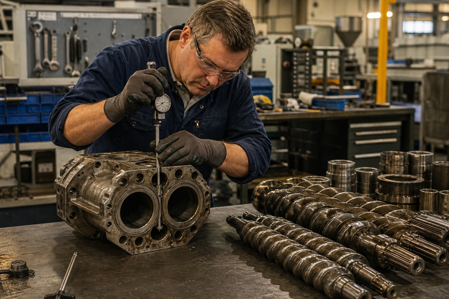
Bore gauging. Measure the barrel inside diameter at multiple points along its length using a telescoping bore gauge or internal micrometer. Focus measurements on zones aligned with kneading blocks and restrictive elements — these are the first areas to exceed tolerance. For moderate-wear applications, quarterly measurements provide a reliable trend line. For high-abrasion compounds, monthly checks are advisable. Industry guidelines suggest that a bore diameter increase of approximately 5% over the original specification across a length of one diameter (1D) signals replacement territory for barrel liners.
Screw OD measurement. Measure the outside diameter of each screw element using a micrometer or calipers. A reduction of roughly 5% from the starting diameter over three-quarters of the element's length is a common replacement threshold. Elements in kneading zones typically reach this point well before conveying elements do, so rotating or repositioning less-worn elements can extend overall screw set life between full replacements.
Screw element rotation and replacement. On modular parallel systems, individual elements can be repositioned along the shaft — moving a lightly worn conveying element into a higher-wear zone, for instance — to equalize wear across the full screw length. This practice extends the interval between full screw set purchases but requires careful tracking of each element's cumulative service hours and current dimensions.
Barrel liner re-sleeving. When bore measurements exceed allowable limits in isolated zones, some barrel segments can be re-sleeved — the worn liner is bored out and a new centrifugally cast liner is applied — rather than replacing the entire barrel. Re-sleeving costs roughly 50-70% of a new barrel segment but restores original bore dimensions and liner integrity, making it a cost-effective option for localized wear on otherwise sound barrel structures.
One critical caution from Plastics Technology's extrusion experts: a screw should never be refurbished more than three times. Each round of hard-facing weld overlay deteriorates the base metal, increasing the risk of delamination between the hard facing and the screw substrate. After three rebuilds, a new screw is the safer and often more economical choice.
Cost of Ownership and ROI Considerations
Purchasing a barrel based on invoice price alone is one of the most expensive mistakes a processor can make. The real cost of any screw and barrel system unfolds over its entire service life, and a total-cost-of-ownership (TCO) framework captures what the purchase order cannot.
Four variables drive TCO:
- Initial component cost. A nitrided barrel segment might cost 1.0x, while a tungsten carbide-lined segment costs 3.0-5.0x. Screw element costs follow a similar multiplier based on alloy grade and hard-facing specification.
- Expected wear life. That nitrided barrel processing a 30% glass-fiber compound might last 2,000-3,000 operating hours before exceeding bore tolerance. A tungsten carbide liner in the same service could deliver 8,000-12,000 hours — three to four times the life at three to five times the initial cost. On a per-hour basis, the premium liner is often the cheaper option.
- Downtime cost during changeover. Every barrel or screw replacement takes the line out of production. On a high-output compounding line producing $500-$1,000 per hour in margin, each hour of unplanned downtime dwarfs the price difference between liner grades. Fewer changeovers directly translate to higher annual throughput and revenue.
- Consequential quality costs. As wear progresses, product consistency deteriorates. Off-spec batches require rework or downgrading, consuming time and material that never appear on the barrel invoice but significantly erode profitability.
The trade-off becomes clear when you run the numbers for your specific operation. A lower-cost nitrided barrel replaced every six months may generate three or four changeovers per year — each consuming a full shift of downtime plus the cost of spare parts, labor, and lost production. A tungsten carbide liner lasting 18-24 months under the same conditions cuts changeovers to one every year or two, compressing total annual spend even though the per-unit barrel price is substantially higher.
The smartest approach? Request wear-life estimates from your barrel supplier based on your exact compound formulation, filler type and loading, throughput rate, and screw speed. Reputable manufacturers of screw extruders maintain wear databases compiled from field installations, and they can provide realistic projections that turn the TCO calculation from guesswork into an engineering decision. Pair those projections with your internal downtime cost and quality-loss data, and the optimal liner grade — and replacement interval — becomes a straightforward financial comparison rather than an assumption.
Keeping a spare screw set and critical barrel segments in inventory is equally important. Experienced process engineers recommend having replacements on hand so that when a worn component reaches end-of-life, the swap can happen during a planned maintenance window rather than forcing an emergency shutdown. The worn screw can then be evaluated for refurbishment or retirement on a timeline that does not hold up production.
Wear management, ultimately, is not a reactive repair activity — it is a design input. The liner grade you specify, the screw elements you sequence, the cooling capacity you provision, and the maintenance intervals you commit to are all interconnected decisions that determine whether your twin screw and barrel investment delivers predictable, economical output year after year. Pulling those decisions together into a single, structured selection framework is the final step toward a fully integrated specification — one that starts with the polymer on your bill of materials and ends with a maintenance schedule on your production calendar.
How to Select the Right Twin Screw and Barrel for Your Application
Liner grades, screw element sequences, polymer compatibility maps, thermal zone strategies, wear lifecycle projections — the preceding sections covered each of these topics in depth. But in practice, they do not exist in isolation. Every specification decision feeds into the next, and the order in which you make those decisions matters. Skip a step or sequence them incorrectly, and you risk specifying a barrel liner that does not match your screw metallurgy, or selecting a screw diameter that your facility's power supply cannot drive at the required RPM.
The following seven-step framework organizes the entire selection process into a logical sequence you can follow from project kickoff through purchase order — whether you are configuring a new twin screw extruder machine or upgrading an existing line.
- Define the polymer and additive package. Start with what you are processing, not what machine you want. List every polymer, filler, fiber, flame retardant, colorant, and liquid additive in your formulations. Note the most abrasive component, the most corrosive off-gas risk, and the highest processing temperature. This data set drives every downstream decision.
- Choose parallel vs. conical configuration. If you compound multiple polymer families, run masterbatch, or need formulation flexibility, parallel co-rotating is the default. If your production is dedicated to PVC profiles or pipe with limited recipe variation, conical counter-rotating earns its place. Verify the actual bore geometry — do not rely on generic labels like "double screw" without confirming whether the machine is parallel or conical.
- Determine L/D ratio and screw diameter. L/D ratio sets your available processing length — more zones for melting, mixing, venting, and side-feeding. A standard compounding line typically needs 40:1 to 44:1. Reactive extrusion or difficult-to-mix materials may push you to 52:1 or beyond. Screw diameter sets throughput capacity: larger diameters allow higher output but require proportionally larger motors and gearboxes. Match diameter to your target throughput range, leaving a 20-30% margin for future growth.
- Select barrel liner metallurgy. Map your compound's dominant wear mechanism — abrasive, corrosive, or combined — to the liner table from the metallurgy section. Unfilled polymers start with nitrided steel. Mineral-filled compounds need iron-based bimetallic. PVC and halogenated chemistries demand nickel-based bimetallic. Glass-fiber-reinforced engineering plastics require tungsten carbide or PM steel. Coordinate barrel liner hardness with screw element materials so neither component wears disproportionately.
- Specify the screw element profile. Work from the polymer compatibility map: define the kneading block angles, mixing element types, and restrictive element placement that match your resin and filler package. If you process glass fiber, position a side-feed downstream of the melt zone and minimize aggressive kneading after the fiber entry point. Build the profile on paper before ordering elements — changing a screw configuration after commissioning is far more expensive than getting it right during specification.
- Plan the temperature zone layout. Align heating and cooling zones with screw element transitions. Ensure adequate cooling capacity in high-shear kneading zones, maintain appropriate thermal balance at vent sections, and verify that the total number of independently controlled zones matches your process complexity. For engineering plastics requiring sustained high temperatures across multiple zones, confirm that heater watt density and cooling water flow rates can handle the thermal load at maximum throughput.
- Establish a maintenance and replacement schedule. Before the machine ships, define bore measurement intervals, screw element rotation plans, and replacement thresholds based on your compound's expected wear rate. Budget for spare screw sets and critical barrel segments so changeovers happen during planned windows rather than emergency shutdowns. Request wear-life projections from your barrel supplier — realistic estimates based on your specific formulation, throughput, and screw speed transform maintenance from guesswork into a predictable operating cost.
That sequence moves from material reality to machine specification to operational planning. Each step constrains the options for the one that follows, preventing the mismatches that plague projects where individual components are sourced independently without a system-level view.
Key Specifications to Evaluate When Sourcing
When you sit down with a twin-screw extruder manufacturer or barrel supplier, you need a common language of numbers — not vague descriptions. The table below lists the critical specifications to collect from any supplier before committing to a purchase, along with typical ranges and the practical reason each one matters.
| Specification | Typical Range | Why It Matters |
|---|---|---|
| L/D ratio | 32:1 to 52:1 (parallel); 20:1 to 28:1 (conical) | Determines available processing length for melting, mixing, venting, and side-feeding. Under-specifying L/D forces compromises in mixing intensity or devolatilization; over-specifying increases capital cost and may degrade heat-sensitive polymers through excessive residence time. |
| Screw diameter | 20 mm to 180+ mm | Sets throughput capacity. Larger diameters support higher output but require proportionally larger motors, gearboxes, and facility utilities. A 75 mm co-rotating twin screw extruder suits mid-volume engineering plastic compounding, while diameters above 90 mm target high-output commodity lines. |
| Maximum RPM | 300 to 1,200 RPM (parallel co-rotating); 50 to 200 RPM (conical counter-rotating) | Higher RPM increases throughput and shear-heat generation. Machines rated for 800+ RPM demand liquid-channel cooling and wear-resistant liners in kneading zones. Verify that the gearbox and motor can sustain max RPM at full torque without thermal derating. |
| Torque density | 5 to 12+ Nm/cm3 | Measures the mechanical strength available per unit of screw volume. High-torque machines (10-12 Nm/cm3) are essential for stiff polymers and high-filler compounds. Under-specifying torque causes frequent overload trips, production stops, and potential material degradation inside the barrel. |
| Number of temperature zones | 4 to 12+ | More zones allow finer thermal profiling. Engineering plastic compounding with multiple processing stages (melting, mixing, venting, die) typically requires 8 to 12 zones. Fewer zones may suffice for simple polyolefin compounding or dedicated PVC lines with narrow thermal windows. |
| Barrel liner material | Nitrided, bimetallic (Fe or Ni-based), tungsten carbide, PM steel | Must match the compound's dominant wear mechanism. Requesting the specific alloy grade, hardness range (HRC), and liner depth (mm) — not just a generic "bimetallic" label — ensures you get the protection your process actually requires. |
| Number and type of barrel openings | 1 to 3 feed ports; 1 to 3 vent ports; 0 to 2 side-feed ports | Defines process flexibility. Recycling lines and multi-additive formulations require more openings than simple single-polymer compounding. Each opening must align with the screw element profile beneath it. |
Collecting these data points from every supplier you evaluate creates an apples-to-apples comparison grid. A twin-screw extruder machine that looks cheaper on the quote may have lower torque density, fewer temperature zones, or a nitrided liner where your compound demands bimetallic — differences that translate directly into higher operating costs, shorter component life, and reduced product quality over the life of the investment.
Working with a Specialist Barrel Manufacturer
You can source a twin screw extruder from one supplier and barrels from another — but the best outcomes typically emerge when at least one partner in the supply chain specializes in barrel engineering for your specific application. A specialist barrel manufacturer brings three capabilities that generalist equipment vendors rarely match:
- Application-specific liner recommendations. Rather than offering a one-size-fits-all bimetallic option, specialists maintain wear databases across dozens of polymer and filler combinations. They can tell you whether an iron-based or nickel-based alloy is the right choice for your 35% CaCO3-filled PP, and whether a WC-CrC-Ni liner outperforms standard WC-Co for your glass-fiber-plus-flame-retardant PA66 compound — before you commit to a purchase.
- Custom barrel section configurations. Compounding, pelletizing, recycling, and masterbatch production each place different demands on barrel layout. A manufacturer that engineers custom parallel twin screw barrels for these applications can recommend the optimal sequence of feed, closed, vent, and side-feed sections — coordinated with your screw element profile — rather than shipping a generic barrel assembly that may or may not match your process needs.
- Screw-to-barrel material pairing guidance. As covered in the metallurgy section, running a premium barrel liner with mismatched screw elements creates uneven wear that shortens the life of the cheaper component. Specialist manufacturers understand these interactions and specify both components as a system, maintaining the two-to-four HRC hardness differential that maximizes combined service life.
NANHAIYA is one example of a specialist resource in this space. Their parallel twin screw barrel portfolio covers mixing, conveying, granulation, and high-wear plastic processing configurations, serving compounding, pelletizing, recycling, and masterbatch operations running twin-screw extrusion lines. For engineers evaluating parallel barrel options, their product page provides a useful starting reference for understanding what custom configurations are available and how barrel design connects to specific processing requirements.
Of course, no single supplier covers every scenario. When sourcing conical barrels for PVC lines, injection molding barrels, or rubber-processing components, you may need to engage different twin screw extruder manufacturers with the relevant specialization. The key principle remains the same regardless of supplier: evaluate manufacturing capability — product range, material options, quality certifications, custom engineering support, and documented wear-life data — rather than selecting on price alone.
A practical sourcing approach looks like this: share your full formulation details, throughput targets, and screw element profile with two or three qualified barrel suppliers. Ask each one to recommend a liner material, specify the expected wear life under your operating conditions, and quote both the initial barrel cost and the projected replacement interval. Then run the total-cost-of-ownership calculation from the previous section. The supplier whose recommendation delivers the lowest annual cost — accounting for component price, expected service hours, downtime during changeover, and quality risk — is the right partner for that application, regardless of where their quote falls on an invoice-price ranking.
Selection is not a single decision — it is a chain of interconnected choices that begins with the polymer on your bill of materials and ends with a maintenance calendar on the production floor. Follow the seven-step sequence, collect the specification data, engage suppliers who understand your application at the barrel-and-screw level, and you will build a twin screw and barrel system that delivers consistent output, predictable costs, and the flexibility to adapt as your product portfolio evolves.
Frequently Asked Questions About Twin Screw and Barrel Systems
1. What is the difference between a parallel and conical twin screw extruder?
A parallel twin screw extruder uses two screws of equal, constant diameter inside a straight figure-eight bore, offering modular element design, L/D ratios from 32:1 to 52:1, and superior formulation flexibility for compounding, masterbatch, and recycling. A conical twin screw extruder features tapered screws that decrease in diameter from feed to discharge, creating natural compression. Conical machines excel in dedicated PVC pipe and profile lines due to high feed-end torque, compact footprint, and gentle positive-displacement conveying that suits PVC's narrow thermal window. Choose parallel for multi-polymer flexibility and conical for dedicated PVC or WPC production.
2. How do I choose the right barrel liner for my twin screw extruder?
Barrel liner selection depends on the dominant wear mechanism in your process. For unfilled commodity polymers like PE or PP, nitrided steel offers adequate protection at the lowest cost. Moderately filled compounds with calcium carbonate or talc call for iron-based bimetallic liners. PVC and halogenated flame-retardant compounds require nickel-based bimetallic liners for corrosion resistance. Glass-fiber-reinforced engineering plastics at 30%+ loading demand tungsten carbide or powder metallurgic steel liners. Always coordinate barrel liner hardness with screw element materials — maintaining a 2-4 HRC differential — to prevent one component from wearing disproportionately faster than the other.
3. What are the main types of screw elements in a twin screw extruder?
Four major screw element categories are used in twin screw systems. Conveying elements use helical flights with varying pitch to transport material forward and build pressure. Kneading blocks consist of staggered oval discs at 30-, 60-, or 90-degree angles to provide dispersive and distributive mixing at different shear intensities. Mixing elements — toothed, gear, or turbine types — distribute additives with lower shear than kneading blocks, preserving sensitive fillers and fiber lengths. Restrictive (barrier) elements, such as reverse-pitch flights, create back-pressure and melt seals for venting. The sequence and combination of these elements along the screw shaft determines overall process performance.
4. How often should twin screw extruder barrels and screws be inspected for wear?
Inspection frequency depends on the material processed. For moderate-wear applications like unfilled or lightly filled polymers, quarterly bore measurements and screw OD checks provide a reliable wear trend. For highly abrasive compounds containing glass fiber or heavy mineral fillers, monthly measurements are advisable. Key indicators of excessive wear include rising motor load at constant throughput, declining specific output rate, higher discharge melt temperatures, and product quality drift such as gels or color streaks. A bore diameter increase of approximately 5% over one diameter length, or a screw OD reduction of about 5% over three-quarters of an element's length, typically signals the replacement threshold.
5. Why is temperature zone management critical in twin screw extrusion?
In high-speed compounding, viscous dissipation from kneading and mixing elements often generates more heat than barrel heaters provide, pushing melt temperatures 15-30 degrees Celsius above setpoints. This makes cooling — not heating — the primary thermal control tool in many zones. Each barrel zone must be independently regulated and aligned with the screw element transitions beneath it. Kneading zones need high cooling capacity to prevent thermal runaway, while venting zones require careful balance to avoid vent flooding or melt plugging. Monitoring actual melt temperature at the die, verifying cooling water flow rates, and adjusting zone setpoints in concert with screw speed changes are essential practices for maintaining consistent product quality and protecting barrel liners from thermally accelerated wear.
Written by
Nanhaiya Technical Team
Zhoushan Nanhaiya Plastic Machinery Co., Ltd.
The Nanhaiya technical team supports screw and barrel manufacturing projects through application review, technical communication, custom manufacturing coordination, and production and quality control.
Discuss Your Application
Related Articles
More insights on screw barrel technology and plastics processing.

What Nobody Tells You About Screw Barrel For Plastic Machine Design
Oct 10, 2026
Learn how screw barrel for plastic machine design affects melt quality, throughput, and wear life. Covers geometry, resin matching, troubleshooting, and sourcing.
Read Article
Single Screw Extruder for Sheet: Stop Guessing, Start Specifying
Oct 9, 2026
Learn how to specify a single screw extruder for sheet production. Covers screw geometry, resin-specific processing, troubleshooting, and maintenance best practices.
Read Article
PE Pipe Extruder Machine: What Datasheets Won't Tell You
Oct 9, 2026
Learn how a PE pipe extruder machine works, key specs explained, material grade selection, maintenance tips, and buyer guidance beyond the datasheet.
Read ArticleLooking for something else?
Search by material, symptom or product and jump straight to the relevant page.
These are navigation suggestions based on keyword matching — not a quotation, not a delivery commitment, and not a substitute for engineering review. Final specification is confirmed by our engineers against your drawings and processed material.
Need help with screw barrel selection?
Share your machine model, processed material and application. Our team can help with pricing and technical support.