

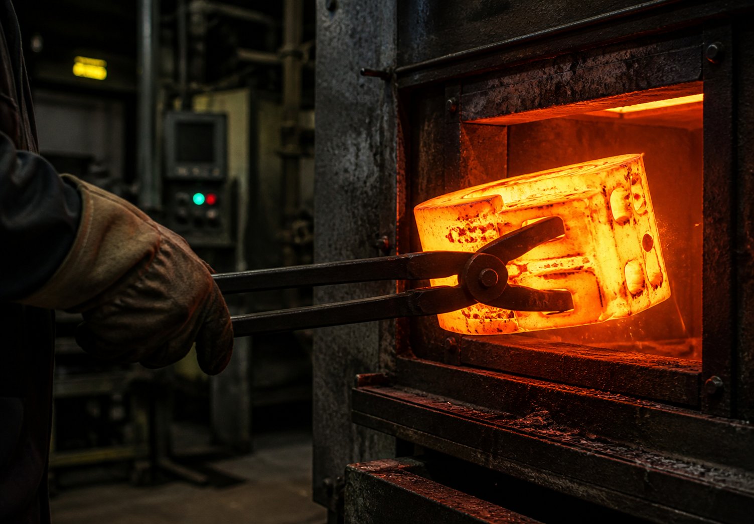
What Is SKD61 Hot Work Tool Steel
When a die casting die cracks after a few thousand shots, or a forging tool softens mid-run, the conversation almost always circles back to one question: was the right steel specified in the first place? More often than not, the answer involves SKD61 — and whether it was heat treated correctly.
SKD61 is a chromium-molybdenum-vanadium hot work tool steel classified under JIS G4404. Engineered for sustained performance at elevated temperatures, it is the most widely used die steel for tooling that contacts hot metal or molten alloys, including aluminum die casting dies, hot forging dies, and extrusion tooling.
If you've searched "skd61 la gi" or wondered about the skd61 材質 designation on a Japanese-supplied die block, you're looking at the same grade — one built specifically to resist the punishing thermal cycles that destroy lesser steels.
What SKD61 Means in the JIS Classification System
The SKD61 meaning traces directly to the Japanese Industrial Standards (JIS) naming convention. In this system, "SK" identifies a steel for tools, the "D" places it in the die steel subcategory, and "61" is the specific grade number. JIS G4404 groups alloy tool steels by function — cutting, cold work, and hot work — and SKD61 sits squarely in the hot work family alongside related grades like SKD6 and SKD62. This classification tells you immediately that the steel was formulated to hold up where temperatures regularly exceed 400-600 degrees Celsius under repeated mechanical loading.
Why SKD61 Matters for Hot Work Applications
Three properties set this SKD61 tool steel apart from general-purpose alternatives. First, it retains working hardness at temperatures that would soften carbon steels or lower-alloy grades. Second, its resistance to thermal fatigue — the network cracking caused by thousands of rapid heat-cool cycles — directly extends die service life. Third, it delivers enough toughness to absorb mechanical shock without chipping or catastrophic fracture, even at elevated temperatures. These characteristics don't appear by accident. They're the direct result of a carefully balanced alloy chemistry — one worth examining element by element.
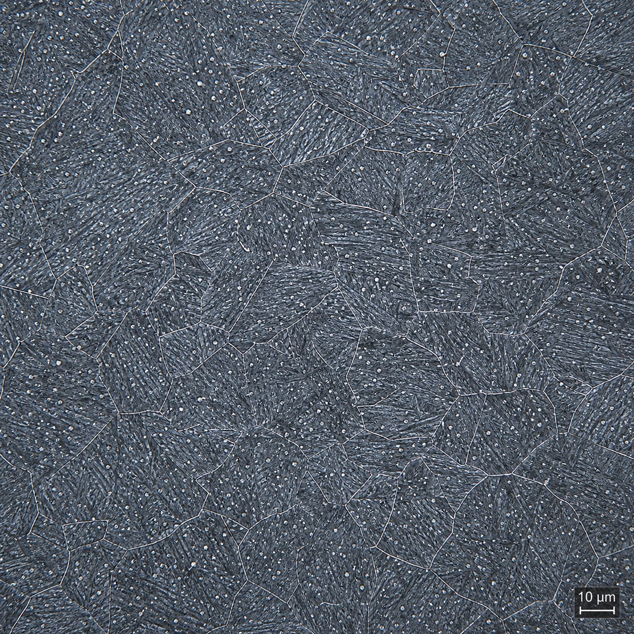
SKD61 Chemical Composition and the Role of Each Alloying Element
A composition table on a datasheet might look like a simple checklist — numbers that either pass or fail. But for a hot work die steel, every tenth of a percent in alloying content shifts the balance between hardness, toughness, and thermal stability. Understanding the SKD61 chemical composition isn't just academic. It's the foundation for predicting how the steel will respond to heat treatment, how long a die will last in service, and why two seemingly identical heats can perform very differently on the shop floor.
Element Ranges per JIS G4404
The table below presents the SKD61 composition as specified under JIS G4404, with each element's weight percentage range and its primary metallurgical function. Keep in mind that exact ranges can shift slightly depending on the standard revision a mill certifies against — always verify against the current JIS G4404 document and the actual mill test certificate for your specific heat.
| Element | Symbol | Weight Percentage Range | Primary Function |
|---|---|---|---|
| Carbon | C | 0.32 – 0.42% | Drives martensitic hardening; controls base hardness and strength |
| Silicon | Si | 0.80 – 1.20% | Deoxidation during steelmaking; improves oxidation resistance |
| Manganese | Mn | 0.25 – 0.50% | Assists hardenability and deoxidation; binds sulfur as MnS |
| Phosphorus | P | 0.030% max | Impurity — segregates to grain boundaries; kept as low as possible |
| Sulfur | S | 0.020% max | Impurity — forms sulfide inclusions that reduce ductility |
| Chromium | Cr | 4.50 – 5.50% | Hardenability, oxidation resistance, and carbide formation |
| Molybdenum | Mo | 1.20 – 1.60% | High-temperature strength; secondary hardening response |
| Vanadium | V | 0.80 – 1.20% | Fine grain control; hard, stable MC-type carbides for wear resistance |
Notice the tight control on impurities. Phosphorus and sulfur caps may look like footnotes, but they matter enormously under cyclic loading — phosphorus embrittles grain boundaries, and sulfur inclusions act as fatigue crack initiation sites. Premium SKD61 steel material produced through electroslag remelting pushes both elements well below these maximums, which is one reason ESR grades outperform conventional melts in demanding die casting applications.
How Each Alloying Element Shapes SKD61 Performance
Reading a mill certificate as a performance indicator — rather than just a pass-or-fail checklist — requires understanding what each element actually does inside the microstructure. Here's where the SKD61 material composition tells its real story.
Carbon (0.32 – 0.42%). Carbon is the engine behind martensitic transformation. It dissolves into austenite during heating, then locks into the crystal lattice during quenching to create the hard martensite that gives the steel its working hardness. The moderate range is intentional — enough carbon to reach useful hardness (typically 44–52 HRC after tempering), but not so much that the steel becomes brittle or prone to thermal shock cracking. In a hot work die, too much carbon is just as dangerous as too little.
Chromium (4.50 – 5.50%). At roughly 5%, chromium is the largest alloying addition after iron. It performs three critical jobs simultaneously. First, it dramatically increases hardenability, allowing thick die sections to transform fully to martensite during air cooling — which is why SKD61 is classified as an air-hardening grade. Second, it forms a thin, adherent oxide layer that protects the die surface from high-temperature oxidation. Third, chromium participates in carbide formation, contributing to wear resistance and temper stability. You'll notice that the ~5% Cr level is a hallmark shared across the entire H13/1.2344/SKD61 family — it's the sweet spot that balances hardenability against toughness.
Molybdenum (1.20 – 1.60%). If chromium is the workhorse, molybdenum is the strategist. Its most important contribution is the secondary hardening response — a phenomenon where hardness actually increases during tempering at 500–600 degrees Celsius instead of decreasing as you'd expect. This happens because molybdenum precipitates as fine, rod-shaped Mo₂C carbides within the tempered martensite matrix. These nano-sized particles pin dislocations, strengthening the steel at exactly the temperatures it encounters during service. Research from the International Molybdenum Association confirms that Mo₂C precipitation can contribute around 200 MPa of additional strength, and that molybdenum also slows the coarsening of other carbides — effectively extending the temperature window where the steel retains its working hardness. This is the element most responsible for preventing dies from softening during extended production runs.
Vanadium (0.80 – 1.20%). Vanadium is the strongest carbide former in the SKD61 steel chemical composition. It creates extremely hard, thermally stable MC-type vanadium carbides (VC) that resist coarsening even at sustained service temperatures of 500–600 degrees Celsius. These carbides serve a dual purpose: they provide excellent abrasion resistance at the die surface, and during austenitizing, they pin austenite grain boundaries to prevent grain coarsening — which directly preserves toughness. Imagine the vanadium carbides as anchors embedded throughout the microstructure, holding the grain structure fine and uniform. Without adequate vanadium, grain growth during heat treatment would reduce toughness and fatigue resistance, both critical properties for a die that cycles thousands of times between hot and cold.
Silicon (0.80 – 1.20%). Primarily carried over from steelmaking as a deoxidizer, silicon also provides modest improvements to oxidation resistance and adds some temper resistance through solid-solution strengthening. However, silicon near the top of its allowable range can reduce toughness — a tradeoff worth checking on the mill certificate for toughness-critical applications like hot forging dies.
Manganese (0.25 – 0.50%). Manganese supports hardenability and reacts with sulfur to form manganese sulfide inclusions, which are less damaging than iron sulfides and reduce the risk of hot shortness during forging. It's kept deliberately low because higher manganese content increases sensitivity to quench cracking — an unacceptable risk in expensive die blocks.
The Secondary Hardening Mechanism — Why It Matters
The real metallurgical signature of SKD61 — and the reason it outperforms plain carbon or low-alloy steels in hot work — is secondary hardening. Here's how it works: during the first temper cycle at 550–620 degrees Celsius, molybdenum and vanadium atoms that dissolved into the austenite during austenitizing begin precipitating out as ultra-fine Mo₂C and VC carbide particles. These particles are small enough (often in the nanometer range) to create powerful obstacles to dislocation movement, producing a hardness peak around 500–550 degrees Celsius that can exceed the as-quenched hardness of simpler steels tempered at the same temperature.
This isn't a subtle effect. It's the defining characteristic that separates hot work tool steels from grades that simply soften continuously during tempering. Without this secondary hardening response, a die operating at 400–600 degrees Celsius would lose its working hardness within the first few hundred production cycles. The interplay between Mo₂C and VC precipitation — combined with the chromium-driven hardenability that ensures a fully martensitic starting structure — is exactly what makes the SKD61 steel material the benchmark for hot work tooling worldwide.
Of course, unlocking this secondary hardening potential depends entirely on proper heat treatment parameters — the right austenitizing temperature to dissolve carbides into solution, the correct quench rate to form martensite, and precise tempering temperatures to trigger precipitation without overaging. That's a subject that deserves its own detailed treatment.
SKD61 Equivalent Materials Across International Standards
Every alloying element discussed above has a precise range defined by the JIS G4404 standard. But what happens when your drawing calls for SKD61 and your supplier quotes H13? Or when a European toolmaker specs 1.2344 and the die block arrives with a JIS mill certificate? Understanding which designations are true equivalents — and where subtle specification gaps can trip you up — is essential for anyone sourcing hot work tool steel across borders.
Global Equivalency Cross-Reference Table
The table below maps the most commonly referenced SKD61 equivalent material designations across major international standards. Each row represents the same fundamental 5% chromium hot work die steel, but the governing specification — and the exact allowable chemistry ranges within it — can differ.
| Standard Body | Designation | Standard Number |
|---|---|---|
| JIS (Japan) | SKD61 | JIS G4404 |
| AISI / ASTM (USA) | H13 | ASTM A681 |
| DIN / EN (Germany / Europe) | 1.2344 / X40CrMoV5-1 | DIN EN ISO 4957 |
| ISO (International) | X40CrMoV5-1 | ISO 4957 |
| GB (China) | 4Cr5MoSiV1 | GB/T 1299 |
| GOST (Russia) | 4Kh5MFS (4X5MФC) | GOST 5950 |
| Sweden (Uddeholm) | ORVAR Supreme / ORVAR 2M | Proprietary (based on H13 chemistry) |
| Sweden (ASSAB) | 8407 | Proprietary (based on H13 chemistry) |
| Austria (Bohler) | W302 / W303 | Proprietary (based on 1.2344 chemistry) |
| BIS (India) | T35Cr5Mo1V30 | IS 3748 |
| KS (South Korea) | STD61 | KS D 3753 |
You'll notice that proprietary designations from premium steelmakers like Uddeholm and Bohler appear alongside national standards. Grades such as ORVAR Supreme and W302 are engineered to the same base chemistry as the jis skd61 equivalent H13, but they're often produced through electroslag remelting or vacuum degassing processes that tighten inclusion counts and improve isotropy — distinctions that matter in high-cavity die casting or long-run forging applications.
Important Notes on Interchangeability
The question of h13 vs skd61 comes up constantly on engineering forums, and the short answer is that the two are near-identical. Both target the same Cr-Mo-V balance and deliver the same working hardness range of 44–52 HRC after proper heat treatment. For the majority of die casting and forging applications, SKD61 and H13 are functionally interchangeable.
The longer answer requires a closer look at the fine print. Several specification-level differences between standards can influence performance in edge cases:
- Carbon range. ASTM A681 permits carbon as wide as 0.32–0.45%, while JIS G4404 typically tightens this to 0.35–0.42%. A wider carbon range introduces more heat-to-heat variability in hardness response.
- Silicon range. The allowable Si window under ASTM (0.80–1.25%) is slightly broader than under JIS (0.80–1.20%). Silicon near the upper boundary can reduce toughness — a meaningful difference for hot forging dies subjected to repeated mechanical shock.
- Phosphorus and sulfur limits. JIS G4404 generally enforces tighter P and S maximums (0.020% S, 0.020% P in many mill practices) compared to ASTM A681's 0.030% caps for both elements. Lower impurity levels improve fatigue life and reduce the risk of grain boundary embrittlement under cyclic thermal stress.
- Manganese range. The Mn window under ASTM H13 (0.20–0.60%) is wider than the JIS specification (typically 0.25–0.50%), which can subtly affect hardenability and quench sensitivity in large cross-sections.
Do these differences mean you should never substitute one for the other? Not at all. For standard aluminum die casting and most hot forging operations, the overlap between SKD61 and H13 is more than sufficient. The chemistry windows share the same core ranges, and the metallurgical behavior under proper heat treatment is effectively identical.
Where caution is warranted is in critical applications — high-cavity die casting molds with tight tolerance requirements, aerospace forging dies, or tooling where the end customer mandates traceability to a specific standard. In those situations, don't assume interchangeability. Validate the actual mill certificate against your application requirements, and confirm that the heat treatment protocol matches the specific steel's composition — not just the generic grade name. ASTM A681, DIN EN ISO 4957, and JIS G4404 remain the authoritative source documents for resolving any ambiguity.
These specification details influence more than just procurement paperwork. The allowable chemistry ranges directly determine a steel's mechanical response — its hardness ceiling, toughness floor, and thermal fatigue resistance under real operating conditions.
Mechanical and Thermal Properties of SKD61
Knowing the chemistry of a steel is only half the picture. What really determines whether a die survives 100,000 shots or cracks at 10,000 is how that chemistry translates into measurable SKD61 properties — hardness, strength, toughness, and the thermal behavior that governs heat flow through the tool during every production cycle. Surprisingly, most technical references stop at a hardness number and a composition table. The thermal data that die designers actually need for cooling channel layout, cycle time optimization, and dimensional stability calculations is almost never published in one place. This section fills that gap.
Mechanical Properties at Room and Elevated Temperatures
The SKD61 mechanical properties listed below represent typical values for material heat treated to a working hardness of 44-52 HRC. Keep in mind that exact numbers depend heavily on three variables: the specific heat treatment cycle applied, the testing direction relative to the forging grain flow, and whether the steel is standard or ESR grade. Always confirm critical design values against the mill's certified test data for your specific heat — a datasheet average is a starting point, not a guarantee.
| Property | Typical Value (Metric) | Typical Value (Imperial) | Notes |
|---|---|---|---|
| Hardness after heat treatment | 44 - 52 HRC | 44 - 52 HRC | SKD61 HRC depends on tempering temperature and application |
| Tensile strength (ultimate) | 1200 - 1590 MPa | 174,000 - 231,000 psi | Increases with higher hardness; measured at 20 degrees C |
| Tensile strength (yield) | 1000 - 1380 MPa | 145,000 - 200,000 psi | Varies with heat treatment condition |
| Elongation | 8 - 14% | 8 - 14% | Higher elongation at lower hardness (44-46 HRC) |
| Impact toughness (Charpy V-notch, unnotched) | 15 - 25 J | 11 - 18 ft-lbs | Longitudinal direction; transverse values typically 60-75% of longitudinal |
| Elastic modulus | 215 GPa | 31,200 ksi | Measured at room temperature |
| Poisson's ratio | 0.27 - 0.30 | 0.27 - 0.30 | Standard for chromium hot work steels |
| Reduction of area | ~50% | ~50% | Indicates good ductility in properly heat treated condition |
A few things stand out in this data. The SKD61 hardness range of 44-52 HRC isn't a single target — it's a deliberate spectrum that engineers select based on the dominant failure mode they're designing against. Hot forging dies that absorb repeated mechanical impact typically run at 44-46 HRC, prioritizing toughness over wear resistance. Aluminum die casting dies, where erosion from high-velocity molten metal is the bigger threat, are usually tempered to 46-50 HRC. Extrusion tooling exposed to sustained high-pressure contact may push toward 50-52 HRC for maximum wear resistance, accepting a modest toughness tradeoff.
The impact toughness values also deserve attention. You'll notice a significant difference between longitudinal and transverse test directions — this anisotropy reflects the elongated sulfide and oxide inclusions aligned with the forging direction. ESR-grade material reduces this directional gap substantially, which is one reason premium grades are specified for dies where crack propagation direction can't be predicted or controlled.
At elevated temperatures — say 400-600 degrees Celsius, where hot work dies actually operate — tensile strength and yield strength drop significantly. The steel retains roughly 70-80% of its room-temperature strength at 400 degrees C and about 50-60% at 600 degrees C. This is where the secondary hardening carbides (Mo₂C and VC discussed earlier) earn their keep, resisting dislocation movement to maintain useful strength levels far longer than plain carbon or low-alloy alternatives.
Thermal Properties Critical for Hot Work Performance
Here's where most datasheets go silent — and where die design decisions are won or lost. The SKD61 thermal properties below directly influence how quickly a die extracts heat from molten metal, how much it expands during each shot cycle, and whether cooling channels are positioned correctly to prevent hot spots. If you've ever searched for an skd61 material properties pdf that includes temperature-dependent thermal data, this table consolidates the values you need.
| Property | 20 degrees C | 200 degrees C | 400 degrees C | 600 degrees C |
|---|---|---|---|---|
| Thermal conductivity (W/m-K) | 24.3 | 26.5 | 27.5 | 28.6 |
| Coefficient of thermal expansion (10-6/degrees C) | — | 10.4 (20-200) | 11.5 (20-400) | 12.4 (20-600) |
| Specific heat capacity (J/kg-K) | 460 | 500 | 540 | 590 |
The SKD61 steel density is approximately 7,750 - 7,800 kg/m³ (0.280 lb/in³), consistent with other 5% chromium hot work steels.
Why do these numbers matter in practice? Consider three scenarios that every die engineer faces:
- Thermal conductivity and cycle time. The skd61 thermal conductivity of roughly 24-29 W/m-K determines how fast the die can pull heat out of molten aluminum (or hot forging stock) and transfer it to the cooling channels. Higher conductivity means faster solidification, shorter cycle times, and better surface finish on the casting. Compared to stainless steels (15-20 W/m-K), SKD61 offers meaningfully faster heat extraction — but it's still well below copper alloys (300+ W/m-K), which is why copper inserts are sometimes used in high-heat-flux zones of die casting molds. Notice that conductivity increases with temperature: the steel actually transfers heat more efficiently at operating temperature than at room temperature, a beneficial characteristic for hot work applications.
- Thermal expansion and dimensional stability. A coefficient of thermal expansion around 10.4-12.4 x 10⁻⁶/degrees C means a 300 mm die dimension will grow by approximately 0.3-0.4 mm when the die surface reaches 400 degrees C. That expansion must be accounted for in cavity dimensions, parting line fit, and ejector pin clearances. Ignoring it leads to flash, dimensional drift on castings, or seized ejector pins. Die designers typically model expansion at the expected average operating temperature — not room temperature — and factor in that expansion coefficients increase at higher temperatures.
- Specific heat and preheat planning. The specific heat capacity tells you how much energy is required to raise the die temperature by one degree. Combined with the die mass and density, this value determines preheat furnace time and energy consumption. A heavy die block at 7,800 kg/m³ with a specific heat of 460-590 J/kg-K absorbs a substantial amount of thermal energy during preheating to the recommended 200-300 degrees C before production. Rushing this preheat step — or skipping it — creates steep thermal gradients between the die surface and interior, setting the stage for thermal fatigue cracking from the very first shot.
These thermal properties also interact with each other in ways that affect die longevity. A die surface that heats rapidly (driven by specific heat and conductivity) but expands against a cooler interior (governed by thermal expansion gradients) generates the compressive-tensile stress cycles that cause heat checking. The balance between conductivity, expansion rate, and cooling channel placement ultimately determines whether thermal fatigue cracks appear at 50,000 cycles or 500,000 cycles — a reality that makes proper heat treatment and die design inseparable decisions.
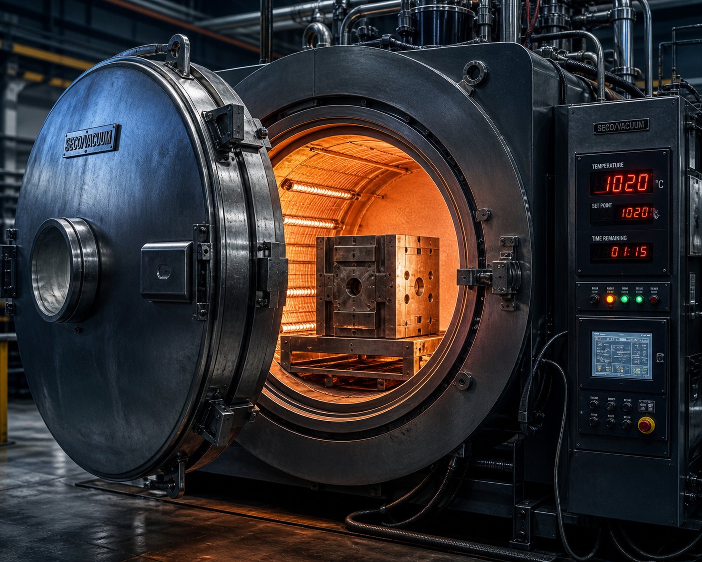
Heat Treatment Procedures for SKD61 Tool Steel
You can buy the cleanest ESR-grade block on the market, machine a perfect cavity, and polish it to a mirror finish — and still destroy the die in production if the SKD61 heat treatment is wrong. That's not an exaggeration. As a senior staff engineer at Honda of America put it plainly: heat treatment is the single most important factor in determining performance of the steel. Every mechanical property listed in the previous section — hardness, toughness, tensile strength — is a direct output of the thermal cycle the steel goes through after machining. Get it right, and the die runs for hundreds of thousands of shots. Get it wrong, and you'll be troubleshooting premature cracking, softening, or dimensional distortion within weeks.
For engineers researching nhiệt luyện thép skd61 or looking for practical guidance on how to process this grade, the procedure breaks into four sequential stages: preheating, austenitizing, quenching, and tempering. Each stage has a specific metallurgical purpose, and skipping or shortcutting any of them compromises the final result.
Austenitizing, Quenching, and Cooling Rate Guidance
Preheating — two stages to avoid thermal shock. SKD61 die blocks are poor thermal conductors relative to their mass. Heating a cold block directly to austenitizing temperature creates dangerous temperature gradients between the surface and core — gradients that can generate internal stresses large enough to crack the die before it ever enters production. The recommended practice uses two preheat holds:
- First preheat: approximately 500 degrees C (930 degrees F). Hold the block at this temperature until the difference between surface temperature and core temperature drops below roughly 110 degrees C (200 degrees F). This stage brings the entire cross-section above the stress-relief range uniformly. The core temperature ramp should not exceed about 220 degrees C per hour (400 degrees F per hour) to prevent thermal shock.
- Second preheat: approximately 850 degrees C (1560 degrees F). Hold until the surface-to-core temperature differential narrows to less than approximately 15 degrees C (25 degrees F), then maintain that temperature for an additional 30 minutes to ensure thorough equalization.
Imagine placing your hand flat on a cold block of steel and pouring boiling water on the back of your hand — the surface wants to expand, but the cold interior won't let it. The same destructive forces act inside a die block during rapid heating, except the stresses involved are high enough to propagate cracks. Proper preheating eliminates this risk.
Austenitizing — dissolving carbides into solution. The furnace is then raised to the austenitizing temperature range, typically 1010-1040 degrees C (1850-1900 degrees F). This is the step where chromium, molybdenum, and vanadium carbides partially dissolve back into the austenite matrix — loading the steel with the alloying elements it needs for secondary hardening during later tempering. The exact temperature within this range depends on the balance you need:
- Lower end (1010-1020 degrees C): Fewer carbides dissolve, preserving more grain-refining VC particles. This produces a tougher, more fatigue-resistant result — ideal for hot forging dies where mechanical shock is the primary failure mode.
- Upper end (1030-1040 degrees C): More carbides dissolve, increasing the secondary hardening potential. This yields higher attainable hardness and better hot wear resistance — suited for aluminum die casting dies and extrusion tooling.
Soaking time at austenitizing temperature depends on section thickness. A general guideline is 15-30 minutes per 25 mm (1 inch) of section thickness after the core reaches the target temperature — long enough for carbide dissolution but short enough to prevent excessive austenite grain growth. Oversized blocks or complex geometries require thermocouple verification, not estimates.
Quenching — the cooling rate that defines everything. This is where most heat treatment failures originate. The workpiece must be cooled rapidly enough from the austenitizing temperature to transform the austenite into martensite — while avoiding thermal shock or distortion. The NADCA guidelines for H13-family steels recommend a minimum cooling rate of about 28 degrees C per minute (50 degrees F per minute) between the austenitizing temperature and approximately 540 degrees C (1000 degrees F). Achieving this rate in less than roughly 18 minutes is the target for full martensitic transformation.
Three quenching media are common for SKD61:
- Pressurized gas (nitrogen or argon): The preferred method for most die casting dies. Vacuum furnaces with high-pressure gas quenching provide uniform cooling with minimal distortion and no surface decarburization. This is the cleanest, most controllable option.
- Oil quench: Provides faster cooling rates, suitable for thick sections where gas quenching may not achieve the minimum required rate. Oil introduces some risk of distortion and requires post-quench cleaning, but it ensures full transformation even in heavy blocks.
- Air cooling: Acceptable only for smaller cross-sections (generally under 150 mm). The relatively slow cooling rate of still air may be insufficient for thick dies, resulting in bainitic or pearlitic transformation products that reduce both hardness and toughness.
This is where the SKD61 CCT diagram becomes a practical decision-making tool. A Continuous Cooling Transformation diagram maps which microstructural phases — martensite, bainite, pearlite — form at different cooling rates. Reading a CCT diagram tells you, for your specific block thickness and quench medium, whether the cooling rate will fall safely to the left of the bainite nose (producing the fully martensitic structure you want) or land in the mixed-transformation zone that compromises properties. As Gear Solutions explains, CCT diagrams are particularly valuable because they allow predictions of hardness and microstructure for real-world continuous cooling — unlike isothermal TTT diagrams, which assume a constant-temperature hold that doesn't occur during actual quenching. One important caveat: published CCT diagrams represent a single composition within the allowable range. Variations in alloying elements between heats — especially chromium, molybdenum, and vanadium — shift the transformation curves, so treat published CCT data as a guide, not an absolute guarantee.
Tempering Procedures and Secondary Hardening Response
Quenching produces a hard but extremely brittle martensitic structure, often with significant retained austenite trapped in the matrix. The steel is essentially unusable in this as-quenched state — it would shatter under the mechanical and thermal loads of die casting or forging. Tempering transforms this brittle martensite into a tough, dimensionally stable tool steel, and for SKD61, the tempering stage is where the real performance magic happens.
Why double (or triple) tempering is mandatory. A single temper cycle is never sufficient for SKD61. The standard practice calls for at least two — and preferably three — full tempering cycles, each at 550-620 degrees C (1020-1150 degrees F), with complete cooling to room temperature between cycles. Multiple cycles are essential for two reasons:
- Retained austenite transformation. During each cooling from the tempering temperature, a portion of the retained austenite transforms to fresh, untempered martensite. The subsequent temper cycle then tempers this new martensite. Without multiple cycles, pockets of brittle, untempered martensite remain in the microstructure — acting as crack initiation sites during thermal cycling. Research on LPBF-manufactured H13 confirmed that retained austenite observed in as-built specimens disappeared only after solution treatment and proper tempering, underscoring the necessity of complete phase transformation.
- Dimensional stability. Each retained austenite-to-martensite transformation involves a volume change. If this transformation occurs in service rather than during controlled tempering, the die distorts — potentially seizing ejector pins, altering cavity dimensions, or cracking at tight-tolerance features. Triple tempering effectively exhausts the retained austenite supply before the die enters production.
The secondary hardening peak — where SKD61 maximum hardness develops. If you plot SKD61 hardness HRC against tempering temperature, you won't see the continuous decline typical of plain carbon steels. Instead, the curve shows a distinctive peak around 500-550 degrees C. This is the secondary hardening response described earlier — the precipitation of ultra-fine Mo₂C and VC carbides from the supersaturated martensite matrix. Studies on H13 tempered at 500 degrees C and 550 degrees C showed hardness recovery to 46-47 HRC (approaching the as-quenched baseline of 47.5 HRC), driven by finely dispersed carbide precipitation within the martensite laths.
The conceptual tempering curve for SKD61 looks like this:
- 200-400 degrees C: Hardness drops slightly as carbon migrates from the martensite lattice and epsilon carbides form. No secondary hardening occurs — the temperature is too low for Mo and V diffusion. Tempering at these temperatures leaves the steel under-tempered and dimensionally unstable for hot work applications.
- 450-550 degrees C: Hardness rises to a peak as Mo₂C and VC carbides precipitate. The SKD61 maximum hardness after tempering — typically 52-54 HRC depending on austenitizing conditions — occurs near this range. This is also where the skd61 硬度 (hardness) data referenced in Japanese technical literature centers.
- 575-650 degrees C: Hardness begins to decline as carbides coarsen and the martensite matrix over-tempers. However, tempering in this upper range delivers significantly higher toughness — the deliberate tradeoff made for applications where fracture resistance matters more than wear resistance.
- Above 650 degrees C: Rapid softening and carbide coarsening. Avoid this range — it destroys both hardness and toughness irreversibly.
A critical warning from research findings: over-tempering is just as damaging as under-tempering. H13 specimens tempered at 500 degrees C for 5 hours or at 550 degrees C for 3 hours showed significant hardness loss (dropping to 41-42 HRC) due to the accumulation and coarsening of carbide precipitates. The finely dispersed carbides that provide secondary hardening gathered into larger, less effective clusters — permanently degrading the steel's mechanical properties. This means tempering time must be controlled as carefully as temperature. Longer is not better.
Target hardness ranges by application. The tempering temperature you choose controls the final hardness, and the right target depends entirely on how the tool will be used:
| Application | Target SKD61 Hardness HRC | Tempering Temperature Range | Prioritized Property |
|---|---|---|---|
| Hot forging dies | 44 - 46 HRC | 600 - 620 degrees C | Maximum toughness and thermal fatigue resistance |
| Aluminum die casting dies | 46 - 50 HRC | 570 - 600 degrees C | Balance of toughness and erosion resistance |
| Extrusion tooling | 48 - 52 HRC | 550 - 580 degrees C | Wear resistance under sustained pressure |
| Plastic mold cores (high-temp resins) | 48 - 52 HRC | 550 - 580 degrees C | Wear resistance and surface hardness |
Improper heat treatment — not material defects, not design errors — is the most common root cause of premature SKD61 tool failure. A perfectly designed die made from premium steel will still fail early if the austenitizing temperature, quench rate, or tempering parameters are incorrect.
This reality makes the heat treatment specification just as important as the steel grade on a purchase order. Specifying "SKD61, 48 HRC" without defining the preheat stages, austenitizing temperature, quench medium, and number of tempering cycles leaves the actual performance up to chance. And when a die does fail prematurely, the investigation almost always traces back to one of these thermal processing steps — not to the steel itself.
Even with flawless heat treatment, though, no die lasts forever. The question becomes: what specific failure modes should you expect, and what practical steps can delay their onset?
Common Failure Modes in SKD61 Tooling and Prevention Strategies
A die doesn't just "break." It degrades through specific, predictable mechanisms — each with its own root cause, warning signs, and countermeasures. Understanding these SKD61 steel properties under real operating conditions, rather than just reading numbers on a datasheet, is what separates a tool that runs for 200,000 shots from one that's pulled for repair at 30,000. Three failure modes account for the vast majority of premature SKD61 tooling retirements: heat checking, erosion, and soldering. Each one attacks the die differently, and each demands a different prevention strategy.
Heat Checking and Thermal Fatigue Cracking
Imagine bending a paperclip back and forth until it snaps. That's essentially what happens to the surface of a die casting die — except the "bending" is driven by temperature, not your fingers, and it happens thousands of times per shift.
Heat checking is the network of fine, spider-web-like surface cracks that develops on SKD61 dies after prolonged exposure to cyclic thermal stress. It's the single most common failure mode in aluminum die casting and a leading cause of die retirement in hot forging operations. The mechanism works like this:
- Heating phase. When molten aluminum (around 670 degrees C) contacts the die surface, the outermost layer heats rapidly and tries to expand. But the cooler interior constrains that expansion, placing the surface under compressive stress.
- Cooling phase. Seconds later, water-based lubricant spray or cooling channel circulation cools the surface rapidly. The surface contracts, but the still-warm interior resists that contraction. The surface stress flips to tension.
- Crack initiation. After thousands of these compressive-tensile cycles, microscopic cracks nucleate at the surface — typically at stress concentrators like sharp radii, EDM-recast layers, or areas of locally high SKD61 material hardness where toughness is insufficient.
- Crack propagation. Once cracks form, the situation accelerates. Research published in the International Journal of Metalcasting (2025) by Okayasu and Shimazu revealed a critical finding: the protective compressive residual stress created by nitriding (~-425 MPa on unused surfaces) completely reverses to damaging tensile stress (~+200 MPa) in heat-checked zones. This stress reversal actively drives cracks deeper with every subsequent cycle. The same study found that molten aluminum infiltrates existing cracks, forming brittle iron-aluminum intermetallic compounds that wedge the cracks open and accelerate propagation.
The brutal reality? Heat checking can never be eliminated entirely. Every hot work die will eventually develop it. The goal is to delay onset and slow progression. Here's how:
- Optimized cooling channel design. Uniform heat extraction across the die surface minimizes localized hot spots — the zones where thermal gradients are steepest and heat checking initiates first. Conformal cooling channels, though more expensive to manufacture, can dramatically reduce surface temperature differentials compared to conventional straight-drilled lines.
- Proper preheat before production. Starting production with a cold die subjects the surface to the most severe thermal shock of its entire service life on the very first shot. Preheating the die to 200-300 degrees C before introducing molten metal reduces the initial temperature differential by 30-50%, significantly lowering the peak tensile stress generated during cooling.
- Controlled cycle times. Rushing cycle times to increase throughput amplifies the thermal gradient per cycle. Allowing adequate cooling time between shots — even a few extra seconds — can reduce peak surface temperature and lower the compressive-tensile stress amplitude that drives fatigue crack growth.
- Higher-toughness heat treatment parameters. This is where the previous chapter's guidance directly impacts die life. Tempering to a lower hardness (44-46 HRC instead of 48-50 HRC) by using a higher tempering temperature (600-620 degrees C) shifts the balance toward toughness and thermal fatigue resistance. The steel absorbs more cyclic strain before cracking. For die casting applications where heat checking is the dominant failure mode rather than erosion, this tradeoff is often the right call.
- Design out stress concentrators. Sharp internal corners, thin cross-sections, and abrupt geometry changes concentrate stress and serve as crack initiation sites. Generous radii and smooth transitions in die cavity geometry delay the onset of heat checking at these vulnerable locations.
Erosion, Soldering, and Wear Failure
While heat checking degrades the die surface gradually over thousands of cycles, erosion and soldering can cause localized damage much faster — sometimes destroying critical features in a fraction of the expected tool life.
Erosive wear occurs when high-velocity molten metal physically removes material from the die surface. In aluminum die casting, gate velocities routinely reach 30-50 meters per second. At those speeds, the liquid metal acts like a sandblaster, attacking sharp corners, gate entries, runner turns, and any feature that deflects the flow stream. Core pins positioned directly in the flow path are especially vulnerable — mold flow simulations have shown that poorly positioned gate angles can erode a core pin to failure in as few as 20,000 shots on a tool designed for hundreds of thousands of cycles. The SKD61 steel hardness in the 46-50 HRC range provides meaningful erosion resistance, but geometry and flow dynamics matter just as much as material properties. Mitigation strategies include:
- Redesigning gate angles to redirect high-velocity flow away from vulnerable features
- Applying surface treatments (nitriding, PVD coatings) to harden exposed surfaces beyond the base steel's capability
- Increasing die hardness in erosion-prone zones — though this requires balancing against reduced toughness
Soldering is a different beast entirely. It's not mechanical wear — it's a chemical reaction. Under the right combination of high temperature, high pressure, and extended contact time, molten aluminum bonds metallurgically with the iron in the die steel surface. The result is a layer of hard, brittle iron-aluminum intermetallic compounds (Fe₂Al₅ and FeAl₃) that welds the casting to the die. Parts stick, ejection forces spike, and attempts to remove soldered material often tear chunks from the die surface — causing more damage than the soldering itself.
Soldering tends to concentrate in areas where the die surface stays hottest longest: deep pockets with poor cooling, areas far from cooling channels, and surfaces where lubricant spray coverage is inconsistent. Prevention targets the root causes:
- Die surface finish. A polished surface reduces the mechanical interlocking that gives aluminum a foothold for chemical bonding. Rough surfaces or EDM-textured zones are far more susceptible.
- Lubricant selection and coverage. Die release agents create a barrier between the aluminum and the steel surface. Consistent, uniform spray coverage is critical — missed spots become soldering initiation sites.
- Protective surface treatments. Nitriding creates a nitrogen-rich compound layer that resists the iron-aluminum reaction. PVD coatings like CrN add an additional physical barrier. Both are discussed in detail in the next section.
- Temperature management. Keeping die surface temperatures below approximately 450 degrees C in aluminum contact zones significantly reduces the thermodynamic driving force for intermetallic formation.
Abrasive wear is the third mechanism — straightforward material removal caused by hard particles or rough surfaces sliding against the die. In die casting, solidified aluminum fragments, oxide particles, and debris from incomplete cavity evacuation all contribute. In hot forging, scale from the workpiece surface is the primary abrasive. Higher SKD61 material hardness (48-52 HRC) and stable vanadium carbides at the surface provide the best defense against abrasive wear, supplemented by nitriding or hard coatings where conditions are severe.
Die Repair Through Welding — Capabilities and Limitations
When erosion, soldering damage, or localized cracking occurs, the question becomes: repair or replace? For expensive die blocks, welding repair is often the economically preferred option — and SKD61 can be welded, though the process demands strict controls.
Successful weld repair of hardened SKD61 requires:
- Complete defect removal. All cracks, oxidized metal, and damaged material must be ground out before welding. If any portion of a crack remains beneath the weld deposit, it will continue propagating in service.
- Rounded groove preparation. A U-shaped groove is preferred over a sharp V-groove. Sharp internal angles concentrate stress and increase the chance of re-cracking at the repair site.
- Preheat to 300-400 degrees C. The preheat temperature should stay below the original tempering temperature of the die to avoid softening the base material. Preheating slows the cooling rate in the heat-affected zone, reducing the likelihood of hard, brittle untempered martensite forming adjacent to the weld.
- H13-matching filler wire. Using a filler that matches the base steel chemistry ensures the repaired area has comparable hardness and hot work performance after post-weld tempering. With proper filler and treatment, repaired zones can reach approximately 52-55 HRC.
- TIG (GTAW) welding. This process offers the best control over heat input and weld placement — critical for precision die repair where excessive heat can distort cavity dimensions or soften adjacent hardened surfaces.
- Post-weld heat treatment. The repaired die must be tempered after welding to relieve residual stress in the weld zone and heat-affected zone. Skipping this step invites delayed cracking — sometimes hours or days after the repair looks complete.
One honest caveat: even a well-executed weld repair produces a heat-affected zone with altered microstructure and SKD61 material properties that differ from the original base metal. The repaired zone typically exhibits reduced thermal fatigue life compared to virgin material. For critical cavity surfaces where heat checking resistance is paramount, weld repair extends useful life but rarely matches the performance of a new die insert. Repeated repairs to the same area compound this degradation — at some point, replacement becomes more cost-effective than another round of welding.
Failure prevention, then, is really a systems problem. Heat treatment sets the baseline toughness and hardness. Die design controls stress concentrations and thermal gradients. Process parameters manage the severity of each thermal cycle. And when all three are optimized together, the remaining question is whether surface treatments can push tool life even further — adding a protective barrier between the steel and the hostile environment it operates in.
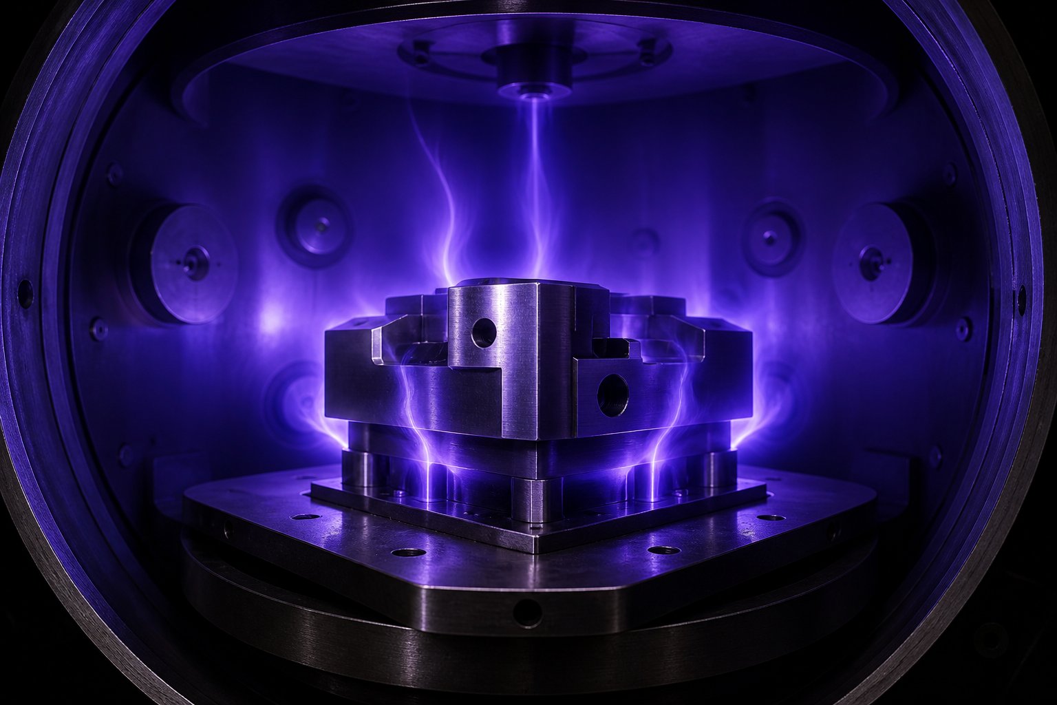
Surface Treatments That Maximize SKD61 Tool Life
That protective barrier between the steel and its hostile operating environment? It's not optional — it's often the difference between acceptable tool life and exceptional tool life. A properly heat treated SKD61 die at 48 HRC already resists erosion, soldering, and thermal fatigue far better than lower-alloy alternatives. But the die surface — the very layer that absorbs molten metal impact, thermal shock, and chemical attack — can be engineered independently from the core. Surface treatments add hardness, chemical inertness, or beneficial residual stresses precisely where they're needed most, without compromising the tough, shock-absorbing core underneath.
Nitriding and Its Impact on SKD61 Surface Hardness
Nitriding is the most widely applied surface treatment for SKD61 tooling, and for good reason. The process diffuses nitrogen atoms into the steel surface at temperatures typically between 500-580 degrees C, creating two distinct zones: a thin, extremely hard compound layer (also called the white layer) at the outermost surface, and a deeper diffusion zone beneath it where nitrogen atoms occupy interstitial sites and form fine alloy nitrides — primarily CrN — with the chromium already present in the steel.
The results are dramatic. The compound layer typically reaches 1000-1200 HV (equivalent to roughly 70+ HRC), while the diffusion zone provides a gradual hardness transition back to the core value. This hardened surface resists adhesive wear, erosive wear, and the iron-aluminum intermetallic bonding that causes soldering — all without altering the die's core toughness or dimensional stability.
Three nitriding methods are commonly used on SKD61 components:
- Gas nitriding. The die is placed in a sealed retort and exposed to a controlled ammonia atmosphere at 500-580 degrees C for 10-60 hours depending on the desired case depth. This is the most traditional approach, producing consistent results on complex geometries. Research by Advanced Heat Treat Corp. demonstrated that H13/SKD61 nitrided at 525 degrees C achieves case hardness above 70 HRC equivalent regardless of core hardness — confirming that even moderately hardened dies benefit substantially from the process.
- Ion (plasma) nitriding. A glow discharge plasma delivers nitrogen ions directly to the workpiece surface in a vacuum chamber. Plasma nitriding offers faster cycle times, better control over compound layer thickness and composition, and the ability to selectively mask areas that should not be nitrided. It produces a cleaner, more uniform gamma-prime compound layer — the preferred microstructure for thermal fatigue resistance, since compressive surface stresses are maintained more reliably.
- Salt bath nitriding. The workpiece is immersed in a molten salt bath containing cyanate and cyanide compounds at approximately 550-580 degrees C. This method is fast and cost-effective for smaller components like SKD61 ejector pins and SKD61 nitrided flat ejector pins. Standard mold components such as straight ejector sleeves with SKD61 and nitriding in JIS head configurations are routinely processed this way. However, environmental regulations increasingly restrict salt bath operations due to the cyanide-bearing waste stream.
One critical rule applies across all three methods: nitriding must always be performed after final heat treatment and tempering, at a processing temperature below the last tempering temperature. If the nitriding temperature exceeds the final temper, the core softens — undoing the careful heat treatment work that established the die's baseline properties. For SKD61 tempered at 580-620 degrees C, this leaves a comfortable processing window. As Advanced Heat Treat Corp. notes, processing temperatures above 1000 degrees F (538 degrees C) are typically feasible for H13-family steels since their hardness peaks near 1100 degrees F tempering, allowing expedited nitriding without core degradation.
PVD Coatings, CVD Coatings, and Shot Peening
Where nitriding modifies the steel's own surface chemistry, coatings add an entirely separate material layer on top of it. Physical vapor deposition (PVD) coatings — typically 1-5 micrometers thick — are the most common coating family applied to SKD61 die casting and molding components.
The three most widely used PVD coatings on hot work tool steel are:
- TiN (titanium nitride). The classic gold-colored coating. It provides good wear resistance, moderate hardness (~2300 HV), and reduces adhesive wear and soldering. A study published in Coatings (2024) by Sutoova et al. tested TiN, TiAlN, and CrAlSiN coatings on die casting inserts under real production conditions. The TiN-coated insert achieved the highest lifetime — 15,000 shots before surface roughness exceeded customer limits — outperforming both TiAlN (12,000 shots) and CrAlSiN (10,000 shots) despite having the highest initial surface roughness. The researchers attributed this to TiN's superior abrasive resistance and the possibility that its rougher surface texture captured more protective lubricant during casting cycles.
- TiAlN (titanium aluminum nitride). Harder than TiN (~3000 HV) and with higher oxidation resistance (stable to approximately 850 degrees C versus 550 degrees C for TiN). It performs well in sustained high-temperature contact zones. However, it has a higher friction coefficient than TiN, which can actually promote soldering in some aluminum die casting scenarios.
- CrN and CrAlSiN (chromium-based nitrides). These offer excellent corrosion resistance, lower friction coefficients than TiAlN, and good thermal stability. Hasco SKD61 ejector pins and core pins — widely used as standardized mold components across Asia and Europe — are frequently offered with CrN or similar PVD options for demanding applications. CrAlSiN in particular provides exceptional thermal stability, making it well-suited for extreme-temperature die casting operations.
CVD coatings (chemical vapor deposition) are deposited at much higher temperatures (850-1050 degrees C) than PVD (200-500 degrees C), producing thicker, more adherent layers. The tradeoff is significant: the high deposition temperature requires a full re-heat treatment of the die afterward, adding cost and complexity. CVD coatings are typically reserved for extreme-wear applications where nothing else lasts long enough — mandrels, extrusion dies, and high-volume forging tools where the coating's adhesion advantages justify the additional processing.
Shot peening takes a completely different approach. Rather than adding hardness or a chemical barrier, shot peening bombards the die surface with small, hard media to introduce compressive residual stresses into the subsurface layers. These compressive stresses directly oppose the tensile stresses generated during the cooling phase of each thermal cycle — effectively raising the threshold for thermal fatigue crack initiation. A study by Sintokogio demonstrated that shot peening the water cooling holes of SKD61 die casting dies induced compressive residual stresses of approximately 1500 MPa and effectively doubled die life compared to non-peened dies in actual production. The treatment also smoothed drilling tool marks inside cooling channels, reducing the stress concentration that otherwise serves as crack initiation sites.
The table below compares each surface treatment option across the key performance dimensions that matter for SKD61 tooling:
| Surface Treatment | Typical Surface Hardness | Key Benefits | Best Application |
|---|---|---|---|
| Gas nitriding | 1000 - 1200 HV | Wear resistance, soldering resistance, fatigue strength improvement | Die casting dies, extrusion tooling, ejector pins and sleeves |
| Ion (plasma) nitriding | 1000 - 1200 HV | Controlled compound layer, selective masking capability, compressive surface stress | Precision die casting inserts, components requiring selective treatment |
| Salt bath nitriding | 900 - 1100 HV | Fast cycle time, cost-effective for small components | Ejector pins, core pins, small standardized mold components |
| PVD coating (TiN) | ~2300 HV | Reduced adhesive wear and soldering, good abrasive resistance | Die casting inserts, core pins in aluminum contact zones |
| PVD coating (TiAlN) | ~3000 HV | High hardness, oxidation resistance to ~850 degrees C | High-temperature extrusion dies, sustained-contact tooling |
| PVD coating (CrN / CrAlSiN) | 2000 - 2500 HV | Corrosion resistance, lower friction, excellent thermal stability | Chemically aggressive environments, hasco SKD61 mold components |
| CVD coating | 2500 - 3500 HV | Thickest, most adherent layers; extreme wear resistance | High-volume extrusion dies, extreme-duty forging mandrels |
| Shot peening | No hardness increase (stress-based) | Compressive residual stress (~1500 MPa), delays thermal fatigue crack initiation | Cooling channel interiors, die cavity surfaces prone to heat checking |
A duplex approach — nitriding first, then applying a PVD coating on top — often delivers the best combined performance. The hard nitrided diffusion zone supports the thin PVD layer and prevents it from cracking under load, while the PVD layer provides chemical inertness against aluminum soldering. Many high-performance die casting operations have adopted this combination as their standard specification for critical cavity inserts and core pins.
Choosing the right surface treatment, though, isn't a one-size-fits-all decision. It depends on the specific processing conditions — the material being formed, the severity of wear and thermal cycling, corrosion risk from process chemicals, and the production volume that must be achieved before maintenance. For screw barrel components in plastics processing, where SKD61 and similar alloys are evaluated alongside surface-treatment options like nitriding and chrome plating, specialists such as NANHAIYA offer material and surface-treatment consultations that match treatment combinations to exact operating conditions — plastic type, filler abrasiveness, corrosion exposure, and throughput targets — ensuring each component is optimized as an integrated system.
Surface treatments push tool life significantly further than heat treatment alone can achieve. Yet the question remains: where exactly does SKD61 perform best, and which industries rely most heavily on its specific property profile?
SKD61 Applications Organized by Industry Process
The answer spans nearly every metalworking and molding operation where tooling contacts hot material under cyclic stress. But lumping all those uses into a single "hot work" label misses the point. Each application loads the steel differently — thermally, mechanically, chemically — and understanding why SKD61's property profile fits each process helps you specify the right hardness range, surface treatment, and grade tier for your specific situation.
Aluminum Die Casting Dies and Hot Forging Dies
Aluminum die casting is the single largest consumer of SKD61 worldwide, and it's easy to see why. The process subjects the die to every failure mode discussed earlier — simultaneously. Molten aluminum at roughly 670 degrees C floods the cavity at gate velocities exceeding 30 meters per second, creating erosive wear at gates and runners. The rapid thermal cycling from injection temperature down to cooling-channel temperature drives heat checking across the cavity face. And the chemical affinity between aluminum and iron promotes soldering on any surface that stays too hot for too long.
SKD61 addresses all three threats in a single alloy. Its secondary hardening response maintains working hardness at 46-50 HRC even after prolonged exposure to 400-600 degrees C. The ~5% chromium content provides oxidation resistance and supports the nitrided compound layer that combats soldering. And the toughness preserved by fine vanadium carbides absorbs thousands of thermal shock cycles before heat checking cracks propagate to critical depth. No other readily available steel grade delivers this combination as cost-effectively — which is why both H13 and SKD61 remain the default die materials for aluminum, zinc, and magnesium die casting operations globally.
Hot forging dies face a different balance of demands. Instead of high-velocity liquid metal, the die contacts solid workpieces at 900-1200 degrees C under massive compressive loads. Mechanical impact — not erosion — is the dominant threat. Here, toughness takes priority over surface hardness. Forging dies are typically tempered to 44-46 HRC to maximize resistance to gross cracking and chipping under repeated hammer blows. The thermal fatigue element is still present (the die surface cycles between forging temperature and lubricant spray temperature every stroke), but the mechanical loading is far more severe than in die casting. SKD61's ability to retain useful toughness at elevated temperatures — roughly 15-25 J Charpy V-notch impact energy even at working hardness — makes it the workhorse for drop forging, upset forging, and press forging of steel, titanium, and nickel-base alloy components.
Plastic Injection Mold Components and Hot Extrusion Tooling
SKD61 might seem like overkill for plastic injection molds — after all, most plastics process at temperatures well below the 400-600 degrees C range where hot work steels earn their keep. But two situations push mold designers toward this grade.
First, high-temperature engineering plastics. Resins like PEI (polyetherimide), PPS (polyphenylene sulfide), and PEEK require mold temperatures of 150-400 degrees C for proper crystallization and surface finish. At these temperatures, pre-hardened mold steels like P20 soften and lose dimensional accuracy. Industry comparisons confirm that SKD61 — with its ability to undergo deep heat treatment to 48-52 HRC — delivers the wear resistance and thermal stability that high-temperature resin processing demands, especially in high-volume or glass-fiber-filled applications where abrasive wear compounds the challenge.
Second, small but critical mold components that endure concentrated mechanical stress. Custom SKD61 mold core pins, for example, must withstand thousands of ejection cycles without bending, galling, or fracturing — all while maintaining tight dimensional tolerances inside a heated mold cavity. SKD61 mold core pins with threaded configurations are particularly common in demanding assemblies where the pin must be securely retained yet replaceable. Many toolmakers who buy SKD61 mold core pins with threaded ends source them from specialized manufacturers in Asia, where China SKD61 mold core pins and SKD61 mold core pins wholesale suppliers offer both standard catalog sizes and custom-machined specials at competitive lead times. The key quality checkpoint when evaluating any SKD61 mold core pins manufacturer is verifiable heat treatment — confirming that the pin reached proper austenitizing temperature, was quenched at an adequate rate, and received multiple tempering cycles to the specified hardness.
Hot extrusion tooling is the other major application area. When aluminum or copper alloy billets are forced through a die at 450-550 degrees C under sustained pressures exceeding 1000 MPa, the die must resist plastic deformation, erosive wear from metal flow, and thermal fatigue from repeated billet loading and unloading. SKD61 tempered to 48-52 HRC provides the hot hardness needed to prevent die deformation, while the stable vanadium carbide dispersion resists the abrasive wear that gradually opens die tolerances and degrades extruded profile dimensions.
Beyond these primary applications, SKD61 appears in a wide range of supporting tooling roles:
- Hot shear blades for cutting heated billets and forgings
- Isothermal forging dies where the die operates at the same temperature as the workpiece
- Mandrels for hot piercing and tube-making operations
- Brass forging dies exposed to dezincification risk and high contact temperatures
- Ejector pins and ejector sleeves — often nitrided for enhanced surface hardness — used as standard components across die casting and injection molding
Across every one of these applications, the common thread is temperature. When tooling operates above 200 degrees C under cyclic conditions, conventional steels soften, warp, or crack. SKD61's engineered alloy chemistry — and the secondary hardening mechanism it enables — is what keeps tools performing in this demanding thermal envelope. The difference between a standard-grade block and a premium ESR-grade block, though, can be just as consequential as the choice of steel grade itself.
ESR and Premium SKD61 Grades for Demanding Applications
Two die blocks arrive at the same heat treatment shop. Both carry mill certificates reading "SKD61, JIS G4404." Both meet the published chemistry ranges. Both receive identical austenitizing, quenching, and double-tempering cycles. Yet one die lasts 250,000 shots in an aluminum die casting cell while the other cracks at 80,000. What went wrong? Nothing visible on the certificate — the difference is buried inside the steel's microstructure, in the size, distribution, and quantity of non-metallic inclusions that no standard composition table captures.
This is where the melting route — how the steel was produced before it ever reached a machine shop — becomes the hidden variable that separates consistent long-run tooling from unpredictable early failures.
ESR vs. Conventional Melting and Why It Matters
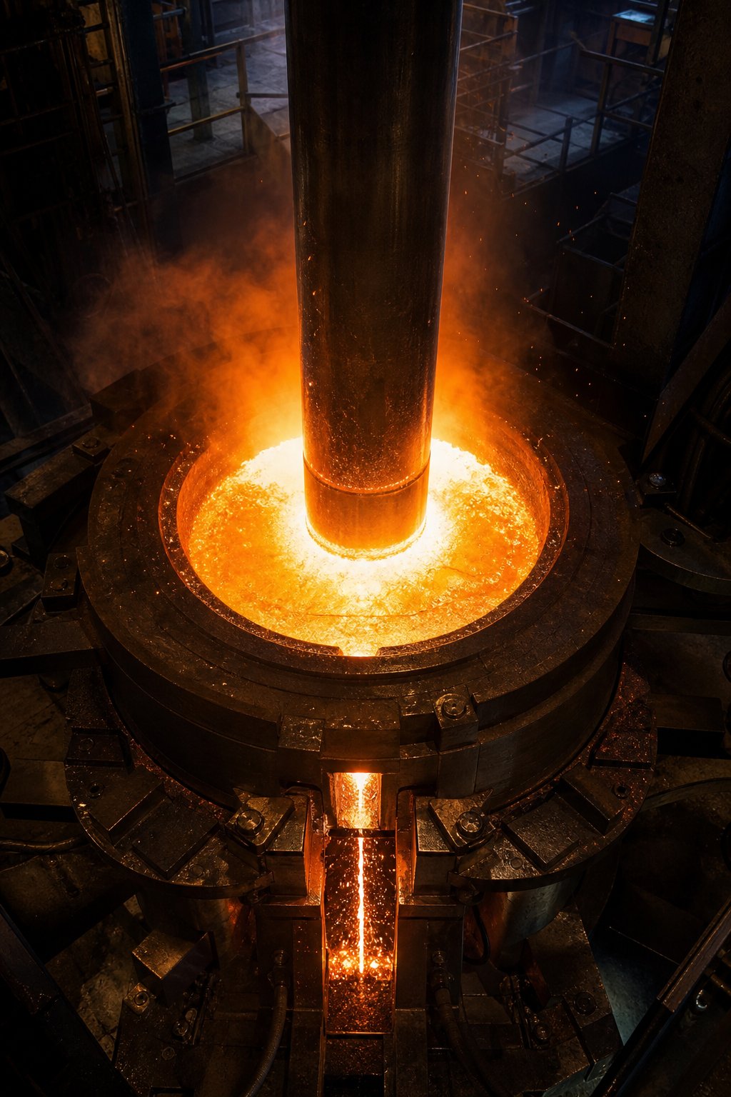
Electroslag Remelting (ESR) is a secondary refining process where a conventionally cast steel electrode is slowly remelted through a pool of superheated, electrically resistive slag. As metal droplets form at the electrode tip and pass through the molten slag, a series of chemical reactions strip out non-metallic inclusions — oxides, sulfides, and complex compounds — that would otherwise remain trapped in the final product. The remelted steel resolidifies progressively in a water-cooled mold, producing an ingot with a dramatically cleaner, more homogeneous internal structure.
The improvements aren't subtle. A peer-reviewed study published in Metals (2024) by Walek, Odehnalova, and Kocich quantified the difference between ESR-processed and vacuum-degassed (VD) structural steel from the same steelworks. The findings paint a clear picture of what ESR delivers:
- Inclusion size reduction. The average non-metallic inclusion size dropped from 19.8 micrometers (VD) to 9.5 micrometers (ESR) — a reduction of more than 50%. Maximum inclusion size fell from 50 micrometers to 28 micrometers.
- Inclusion morphology improvement. In ESR material, 90% of remaining inclusions were globular — the least damaging shape for fatigue resistance. Conventionally produced steel retained elongated and sharp-edged inclusions that act as far more effective stress concentrators.
- Dramatically better toughness. Notched toughness at 20 degrees C increased by 45.5%, and at -40 degrees C it increased by 29.7%. These aren't marginal gains — they represent fundamentally different crack resistance behavior under cyclic loading.
- Improved ductility without strength loss. Elongation increased by nearly 10% and reduction of area improved by 17.7%, even while tensile strength simultaneously increased by 4.2%. ESR eliminated the typical strength-versus-ductility tradeoff.
Why do smaller, fewer, rounder inclusions matter so much for a hot work die? Because inclusions are where cracks start. Every oxide stringer or sulfide cluster embedded in the steel acts as a microscopic stress concentrator — a pre-built initiation site for thermal fatigue cracking, mechanical fracture, or polishing defects. Under the thousands of thermal cycles a die casting die endures, these inclusion-initiated cracks propagate through the die wall, eventually reaching a critical length that forces retirement. Cleaner steel doesn't make the die invincible, but it pushes the crack initiation threshold significantly further into the tool's service life.
ESR also improves isotropy — the uniformity of properties in all directions. Conventionally forged steel develops elongated inclusion stringers aligned with the working direction, creating a measurable difference between longitudinal and transverse toughness. ESR material, with its smaller, globular inclusions and more uniform carbide distribution, narrows this gap. For dies where crack propagation direction is unpredictable — complex cavity geometries, multi-core assemblies — this directional consistency is essential. The same study confirmed that metallographic cleanliness ratings improved from K4 scale (highest contamination) under VD processing to K0-K2 levels under ESR, per the DIN 50602 standard.
Beyond inclusion control, ESR suppresses macrosegregation — the large-scale compositional banding that develops during conventional ingot solidification. Segregated zones experience different heat treatment responses than the surrounding matrix, creating localized hard spots or soft regions that concentrate stress and accelerate failure. The progressive solidification inherent to the ESR process produces a more chemically uniform cross-section, meaning the die responds more predictably and consistently to austenitizing, quenching, and tempering.
Selecting Between Standard and Premium SKD61 Grades
Does every die need ESR-grade material? Absolutely not. The decision comes down to a simple cost-benefit analysis: does the premium price of ESR steel pay for itself through extended tool life, reduced downtime, or improved part quality?
The table below frames the practical differences between the two SKD61 steel grade tiers:
| Characteristic | Standard SKD61 | ESR SKD61 |
|---|---|---|
| Inclusion content | Meets JIS G4404 limits; inclusions up to 50+ micrometers possible | Significantly reduced; average size typically under 10 micrometers |
| Isotropy (property uniformity) | Moderate — transverse toughness typically 60-75% of longitudinal | High — directional property gap substantially narrowed |
| Toughness (Charpy V-notch) | Standard range for the grade | Up to 45% higher at room temperature; ~30% higher at sub-zero temperatures |
| Polishability | Acceptable for most applications; occasional pit-outs from inclusions | Superior — fewer surface defects during high-gloss polishing |
| Typical applications | Moderate-duty forging dies, short-run die casting, standard ejector components | High-cavity die casting dies, long-run mold cores, aerospace forging tooling |
| Relative cost | Baseline | 15-30% premium (varies by supplier and section size) |
Standard-grade material — produced through electric arc furnace melting followed by ladle refining and vacuum degassing — is perfectly adequate for moderate-duty applications. Short production runs, lower-cavity dies, standard ejector pins, and tooling where replacement cost and downtime are manageable all fall into this category. When reviewing an SKD61 steel data sheet from a conventional mill, you'll see chemistry that meets the JIS specification, and hardness after heat treatment that falls within the expected 44-52 HRC window. For many shops, that's all they need.
ESR and vacuum-degassed premium grades justify their cost when the consequences of early failure are severe. Think high-cavity aluminum die casting molds running 24/7 where a single unplanned die change costs thousands of dollars in lost production. Or long-run plastic mold cores for medical or automotive components where surface quality standards demand zero polishing defects. Or large forging dies where the raw material cost is dwarfed by the machining and heat treatment investment — losing a die block early means losing weeks of shop time, not just the steel price. For buyers sourcing custom wholesale SKD61 steel in these premium tiers, verifying the melting route on the mill certificate is just as important as confirming the chemistry. An ESR designation — or equivalent certifications like NADCA Premium or Superior grade — provides documented assurance that the steel's internal quality matches the application's demands.
One additional consideration: CCT (Continuous Cooling Transformation) diagrams may differ slightly between standard and ESR grades of the same nominal composition. The lower inclusion content and more uniform alloying element distribution in ESR material can shift transformation curves marginally, potentially affecting the minimum cooling rate required for full martensitic transformation. In practice, this difference is small enough that the same heat treatment protocol works for both tiers — but for thick-section dies near the critical cooling rate threshold, it's worth reviewing the specific grade's CCT data rather than relying on generic published curves.
Ultimately, selecting between OEM SKD61 steel in standard versus premium tiers is a decision about failure cost, not material cost. When the cost of a cracked die — measured in downtime, scrap, expedited replacement, and customer delivery delays — exceeds the 15-30% premium for cleaner steel, the economics answer the question for you. And for shops producing bulk custom SKD61 steel orders for high-reliability applications, specifying the melting route upfront avoids the far more expensive discovery that conventional material wasn't clean enough after the die has already failed in production.
Selecting the Right SKD61 Specification for Your Application
Failure cost versus material cost. That framing applies not just to the standard-versus-ESR decision, but to every choice in the specification chain — grade tier, heat treatment parameters, surface treatment, and even which SKD61 steel supplier you trust with the order. Each decision interacts with the others. Specifying premium steel but skipping proper tempering wastes the investment. Choosing the right hardness but ignoring surface treatment leaves performance on the table. The engineers who get the best results treat these variables as a single integrated system, not a series of isolated line items on a purchase order.
Matching SKD61 Grade and Heat Treatment to Your Application
Five variables drive every specification decision: what process the tool supports (die casting, forging, plastic molding, extrusion), the operating temperature range, the expected production volume before maintenance, surface finish requirements on the formed part, and the budget available for tooling. Miss any one of these, and you're guessing — and guessing with a tool steel that costs hundreds or thousands of dollars per block is an expensive habit.
Here's the step-by-step framework that ties together everything covered in this article:
- Define operating conditions precisely. Identify the peak die surface temperature, the thermal cycling frequency, the contact material (molten aluminum, hot steel billet, glass-filled polymer), and the dominant failure mode you're designing against — heat checking, erosion, soldering, or mechanical fracture. This single step eliminates most specification errors before they start.
- Select standard versus ESR grade. For moderate-duty tools, short production runs, or applications where replacement cost is manageable, standard-grade SKD61 from a reputable SKD61 steel manufacturer delivers reliable performance at baseline SKD61 steel price levels. For high-cavity die casting molds, long-run mold cores, or any die where unplanned downtime costs dwarf the SKD61 material price premium, specify ESR or vacuum-degassed premium grades — and verify the melting route on the mill certificate, not just the chemistry.
- Specify heat treatment parameters and target hardness. Don't write "SKD61, 48 HRC" and assume the heat treater will figure out the rest. Define preheat stages, austenitizing temperature (lower end for toughness, upper end for wear resistance), quench medium, and number of tempering cycles. The target hardness range — 44-46 HRC for forging, 46-50 HRC for die casting, 48-52 HRC for extrusion — should be a deliberate engineering decision, not a default.
- Choose the appropriate surface treatment. Match the treatment to the threat: nitriding for soldering and wear resistance, PVD coatings for chemical inertness in aluminum contact zones, shot peening for thermal fatigue crack delay. A duplex approach — nitriding plus PVD — often delivers the best combined performance for critical die casting cavity inserts.
- Establish die maintenance and inspection intervals. Even a perfectly specified die degrades over time. Define inspection schedules for heat checking depth, erosion measurement at gates, and soldering buildup — then tie those inspections to predetermined maintenance actions (re-nitriding, weld repair, replacement) before damage reaches the point of catastrophic failure.
When sourcing material, the landscape of SKD61 steel suppliers ranges from integrated SKD61 steel factory operations that melt, forge, and heat treat in-house to SKD61 steel distributors that stock pre-cut blocks from multiple mills. SKD61 steel china suppliers have become major players in the global market, offering competitive pricing on both standard and premium grades. Regardless of source, the non-negotiable quality checkpoint remains the same: a traceable mill certificate that confirms chemistry, melting route, and delivery condition against your specified requirements.
Getting Expert Guidance on Material and Surface Treatment Selection
The five-step framework above works — but only when each step is informed by the others. Selecting a hardness target without considering the surface treatment that will follow, or choosing a surface treatment without factoring in the operating temperature, creates blind spots that show up as premature failures on the production floor.
Material selection without surface treatment planning leaves performance on the table. The steel grade, heat treatment cycle, and surface engineering must be specified as a unified system — not three independent decisions made by three different departments.
This integrated approach is especially critical for processing equipment components where material, treatment, and operating conditions are tightly coupled. Screw barrel assemblies in plastics processing, for instance, face a complex matrix of wear from abrasive fillers, corrosion from aggressive polymers, and thermal cycling from zone-to-zone temperature variation. Specialists like NANHAIYA apply exactly this systems-level methodology — recommending specific material and surface-treatment combinations (including alloys like SKD61, nitriding, chrome plating, and alternative wear-resistant options) based on the processor's plastic type, filler content, corrosion exposure, and production throughput. Rather than specifying a screw material in isolation and hoping the surface treatment compensates for any mismatch, their approach evaluates the entire operating environment first, then works backward to the material-treatment pairing that delivers the lowest total cost of ownership.
That same principle applies whether you're specifying a die casting die, a forging tool, or a mold core pin. The steel is not the solution — the system is. Get the chemistry, the heat treatment, and the surface engineering working together, and SKD61 delivers exactly what it was designed for: sustained, predictable performance at the temperatures where lesser steels fail.
Frequently Asked Questions About SKD61 Tool Steel
1. What is the difference between SKD61 and H13 tool steel?
SKD61 (JIS G4404) and H13 (ASTM A681) are near-identical 5% chromium hot work tool steels that share the same Cr-Mo-V alloy balance and deliver a working hardness of 44-52 HRC. However, minor specification differences exist. JIS G4404 typically enforces tighter phosphorus and sulfur limits (0.020% max vs. 0.030% max under ASTM), and the allowable silicon and carbon ranges differ slightly. These small variations can affect toughness and heat treatment response in critical applications. For standard aluminum die casting and most hot forging, the two grades are functionally interchangeable, but direct substitution in high-reliability tooling should be validated against actual mill certificate data and specific application requirements.
2. What is the recommended heat treatment for SKD61?
Proper SKD61 heat treatment involves four stages. First, two-stage preheating to approximately 500 degrees C then 850 degrees C to prevent thermal shock cracking. Second, austenitizing at 1010-1040 degrees C with soaking time based on section thickness (15-30 minutes per 25 mm). Third, quenching via pressurized gas, oil, or air cooling (for small sections) at a minimum rate of 28 degrees C per minute down to 540 degrees C. Finally, double or triple tempering at 550-620 degrees C with complete cooling to room temperature between cycles. Multiple temper cycles are mandatory to transform retained austenite and achieve dimensional stability. Target hardness ranges from 44-46 HRC for forging dies up to 48-52 HRC for extrusion tooling.
3. What are the main applications of SKD61 tool steel?
SKD61 serves any tooling application involving sustained high-temperature contact and cyclic thermal stress. Its largest use is aluminum die casting dies, where it resists erosion, soldering, and heat checking simultaneously. Hot forging dies for steel and titanium components rely on SKD61 tempered to 44-46 HRC for maximum toughness. It is also used in plastic injection mold cores for high-temperature resins like PEEK and PPS, hot extrusion dies for aluminum and copper profiles, ejector pins, ejector sleeves, hot shear blades, mandrels, and isothermal forging dies. Specialists like NANHAIYA (nhyscrew.com/services/custom-screw-design) also evaluate SKD61 alongside nitriding and chrome plating for screw barrel components in plastics processing equipment.
4. What causes SKD61 dies to fail prematurely?
The most common root cause of premature SKD61 failure is improper heat treatment - not material defects or design errors. Insufficient preheat stages, incorrect austenitizing temperature, inadequate quench rate, or skipping multiple tempering cycles all compromise the steel's mechanical properties. Beyond heat treatment errors, three operational failure modes dominate: heat checking (thermal fatigue cracking from cyclic heating and cooling), erosion (material removal by high-velocity molten metal at gate areas), and soldering (chemical bonding of aluminum to the die surface). Prevention strategies include optimized cooling channel design, proper die preheat to 200-300 degrees C before production, controlled cycle times, surface treatments like nitriding or PVD coatings, and selecting the correct hardness-toughness balance for the specific application.
5. Is ESR-grade SKD61 worth the extra cost?
ESR (Electroslag Remelted) SKD61 reduces average inclusion size by over 50%, improves Charpy V-notch toughness by up to 45%, and significantly enhances isotropy compared to conventionally melted material. These improvements translate directly to longer die life and more predictable performance under cyclic thermal stress. ESR is justified for high-cavity die casting molds running continuously, long-run mold cores requiring defect-free polished surfaces, and large forging dies where machining and heat treatment investment far exceeds the raw material cost. For moderate-duty applications, short production runs, or standard ejector components, conventional-grade SKD61 delivers reliable performance at lower cost. The decision ultimately hinges on whether the 15-30% material premium is offset by reduced downtime and extended tool life.
Written by
Nanhaiya Technical Team
Zhoushan Nanhaiya Plastic Machinery Co., Ltd.
The Nanhaiya technical team supports screw and barrel manufacturing projects through application review, technical communication, custom manufacturing coordination, and production and quality control.
Discuss Your Application
Related Articles
More insights on screw barrel technology and plastics processing.

What Nobody Tells You About Screw Barrel For Plastic Machine Design
Oct 10, 2026
Learn how screw barrel for plastic machine design affects melt quality, throughput, and wear life. Covers geometry, resin matching, troubleshooting, and sourcing.
Read Article
Single Screw Extruder for Sheet: Stop Guessing, Start Specifying
Oct 9, 2026
Learn how to specify a single screw extruder for sheet production. Covers screw geometry, resin-specific processing, troubleshooting, and maintenance best practices.
Read Article
PE Pipe Extruder Machine: What Datasheets Won't Tell You
Oct 9, 2026
Learn how a PE pipe extruder machine works, key specs explained, material grade selection, maintenance tips, and buyer guidance beyond the datasheet.
Read ArticleLooking for something else?
Search by material, symptom or product and jump straight to the relevant page.
These are navigation suggestions based on keyword matching — not a quotation, not a delivery commitment, and not a substitute for engineering review. Final specification is confirmed by our engineers against your drawings and processed material.
Need help with screw barrel selection?
Share your machine model, processed material and application. Our team can help with pricing and technical support.