

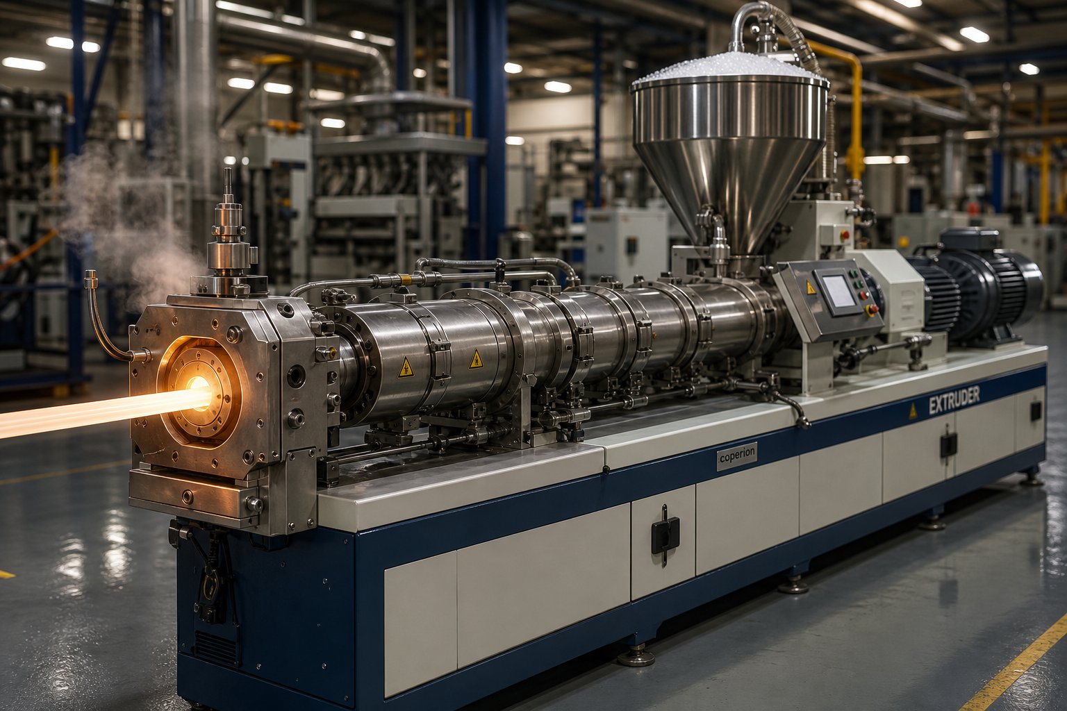
What Is a Single Screw Plastic Extruder and Why It Matters
Imagine a machine responsible for creating everything from the water pipes in your home to the plastic film wrapped around your groceries. That machine is almost certainly an extruder - and odds are, it has a single screw at its core. But what is a plastic extruder, exactly, and why does this particular design show up in nearly every plastics factory on the planet?
Definition and Working Principle
A single screw plastic extruder is a continuous-processing machine that uses one rotating screw housed inside a heated barrel to melt, mix, and push thermoplastic material through a shaped die, producing an uninterrupted profile. Raw plastic - typically fed as pellets, granules, or powder - enters through a hopper, gets conveyed forward by the screw's helical flights, and progressively melts through a combination of barrel heat and frictional shear energy. By the time the molten polymer reaches the die at the far end, it has been homogenized into a consistent melt stream ready to be shaped into its final form.
A single screw plastic extruder is a machine that uses a single rotating screw inside a heated barrel to melt, mix, and convey thermoplastic material through a shaped die, producing continuous products such as pipe, film, sheet, profiles, wire coating, and filament.
The elegance of this plastic extrusion machine lies in the screw itself. As it rotates - driven by a gearbox and motor - it performs three jobs simultaneously: it transports solid material forward, generates and transfers heat to melt the polymer, and builds the pressure needed to force the melt through the die. The melting process relies on both conductive heating from the barrel's external heaters and viscous dissipation, which is the heat generated by the polymer being sheared and compressed between the screw flights and barrel wall.
Why Single Screw Designs Dominate Plastics Processing
You might wonder why this design has remained the industry workhorse for decades. The answer comes down to four practical advantages that matter most on a factory floor:
- Simplicity: A single screw extruder has a straightforward mechanical structure - one screw, one barrel, one drive system. Fewer moving parts mean fewer failure points and easier troubleshooting.
- Lower capital cost: Compared to more complex alternatives, the initial investment is significantly smaller, making it accessible to operations of all sizes.
- Reliability: These machines are built for continuous, round-the-clock production. Their robust construction translates to long service life with relatively modest maintenance demands.
- Broad material compatibility: A well-configured single screw extruder handles the vast majority of commodity thermoplastics - polyethylene (PE), polypropylene (PP), polystyrene (PS), and PVC - as well as engineering polymers like ABS, PA, and even PEEK.
This combination of low cost, operational simplicity, and material versatility is precisely why the single screw extruder remains the default choice for producing pipes, blown and cast films, flat sheets, window profiles, wire and cable coatings, 3D-printer filament, and countless other products. It is, by a wide margin, the most commonly deployed extrusion technology in the plastics industry.
Single Screw vs Twin Screw at a Glance
If the single screw design is so dominant, where does a twin screw extruder fit in? The distinction is important for anyone evaluating equipment. A twin screw machine uses two intermeshing screws rotating inside a figure-eight barrel, providing superior mixing, degassing, and the ability to handle contaminated or highly filled materials. That extra capability comes at a price - higher capital cost, more complex maintenance, and greater operational complexity.
| Factor | Single Screw Extruder | Twin Screw Extruder |
|---|---|---|
| Design Complexity | Simple - one screw, one barrel | Complex - two intermeshing screws |
| Capital Cost | Lower | Higher |
| Mixing Capability | Adequate for most applications | Excellent - ideal for compounding |
| Maintenance | Easier and less frequent | More involved and costly |
| Best Suited For | Clean, consistent materials; pipe, film, sheet, profile production | Compounding, reactive extrusion, contaminated or blended feedstocks |
| Energy Efficiency | Generally higher for equivalent throughput | Can be higher per unit of qualified output in complex applications |
Think of it this way: for the majority of plastics processing tasks - where the feedstock is reasonably clean and the goal is to produce a shaped product efficiently - a single screw extruder is the right tool. Twin screw machines earn their place in compounding, reactive processing, and advanced recycling scenarios where intensive mixing and degassing are non-negotiable. The two technologies are complementary, not competing.
With that foundation in place, the real question becomes: what exactly is happening inside that barrel? The answer lies in understanding the individual components that make up the system - and how each one influences the quality of what comes out of the die.
Essential Components of an Extruder Machine for Plastic and How They Work Together
Every piece of extruder equipment on the factory floor might look like a single machine, but it is actually a tightly coordinated system of interdependent components. Swap out one element - or let it degrade - and the entire output shifts. Understanding what each part does, and how it communicates with everything else in the system, is the difference between running a line that produces consistent, high-quality product and one that generates scrap and headaches.
Here is a complete reference table you can bookmark. We will unpack each group in detail below.
| Component | Function | Key Design Consideration |
|---|---|---|
| Hopper | Stores and gravity-feeds raw material (pellets, granules, powder) into the barrel | Capacity sizing; inclusion of drying or blending attachments for moisture-sensitive resins |
| Feed Throat | Channels material from hopper into the barrel's feed opening; maintains cool temperature to prevent premature melting | Water-cooled jacket to avoid pellet bridging or sticking |
| Barrel (Cylinder) | Houses the screw; provides the containment vessel where melting and conveying occur | Liner material (nitrided steel, bimetallic alloys) chosen for abrasion and corrosion resistance |
| Screw | Conveys, melts, mixes, and pressurizes the polymer as it rotates | Geometry (L/D ratio, compression ratio, flight depth) matched to target polymer and application |
| Heating Bands | Supply external heat to the barrel to initiate and maintain polymer melting | Type (mica, ceramic, cast aluminum) affects heat transfer rate and energy efficiency |
| Cooling Channels / Fans | Remove excess heat to prevent thermal degradation and maintain set-point accuracy | Air-cooled vs. liquid-cooled; response speed must complement heater output |
| Thermocouple Sensors | Measure barrel zone temperatures and feed data back to the controller | J-Type (0-760 °C) is most common; dual-thermocouple setups minimize temperature fluctuations |
| Breaker Plate | Converts the screw's rotating spiral flow into uniform linear flow; supports the screen pack | Hole pattern (size, count, arrangement) determines pressure drop and flow uniformity |
| Screen Pack | Filters contaminants, unmelted particles, and gels from the melt stream | Mesh count selected for target filtration level; finer screens increase back pressure |
| Adapter | Connects the barrel/breaker-plate assembly to the die head; provides a smooth flow transition | Internal geometry must avoid dead spots where polymer can stagnate and degrade |
| Die Head | Shapes the molten polymer into the desired cross-sectional profile | Die geometry and land length tuned to specific product dimensions and polymer rheology |
The Hopper, Feed Throat, and Material Intake System
Processing begins before any plastic touches the screw. The hopper - essentially a funnel-shaped reservoir mounted on top of the barrel - stores raw material and feeds it by gravity into the feed throat. Sounds simple, right? It is, until the material refuses to flow. Powdery resins can bridge and form an arch above the opening. Hygroscopic polymers like nylon or PET can absorb moisture in the hopper, leading to splay defects downstream. That is why many operations integrate desiccant dryers, dehumidifiers, or gravimetric blenders directly at the hopper stage.
Beneath the hopper sits the feed throat, a short channel that directs material into the barrel's feed opening. This throat is deliberately water-cooled to keep temperatures low enough that pellets slide freely rather than softening and clogging. If the feed throat overheats - a common issue when cooling water flow drops - pellets will begin to stick and agglomerate, starving the screw of material and causing output fluctuations that ripple through the entire line.
Barrel, Heating Bands, and Temperature Control
The barrel is the containment vessel where transformation happens. It is a precision-machined steel cylinder, typically lined with hardened or bimetallic alloys to resist the abrasive and corrosive forces that different polymers impose. Inside this barrel, the plastic extruder screw rotates - and together they form the heart of the system. Any wear in the screw-barrel fit (increased clearance between the screw flights and barrel wall) directly undermines output rate, melt consistency, and dimensional accuracy of the final product.
Wrapped around the barrel's exterior are heating bands, divided into individually controlled zones. These heaters supply the external energy that initiates melting in the early barrel sections and fine-tunes melt temperature further downstream. Ceramic heater bands deliver faster heat transfer and better energy efficiency than older mica-style bands, a distinction that adds up over thousands of operating hours.
Temperature regulation, however, is not just about adding heat. Cooling channels or blower fans are installed alongside the heaters to remove excess thermal energy - particularly important because the plastic extrusion screw generates significant frictional (shear) heat as it works the polymer. The balance between heating and cooling is governed by thermocouple sensors embedded in the barrel wall. As noted in Davis-Standard's control-functionality overview, J-Type thermocouples are the industry standard, covering a range of 0 to 760 °C, and dual-thermocouple configurations - placing sensors in both the barrel and the heat source - can significantly reduce temperature fluctuations by allowing PID controllers to anticipate changes rather than merely react to them.
You will notice that temperature control appears deceptively simple from the operator panel: set a value, watch it stabilize. In reality, each zone's set-point interacts with neighboring zones, with screw speed, and with the polymer's own thermal properties. Getting this interplay right is what separates a well-tuned extruder from one that produces inconsistent melt.
Breaker Plate, Screen Pack, and Die Head Assembly
Once the polymer has been melted and homogenized by the screw, it encounters the breaker plate - a thick metal disk perforated with numerous holes, positioned between the end of the screw and the die. The breaker plate performs two critical jobs. First, it converts the screw's rotational, spiral-patterned melt flow into a straighter, more uniform stream. Second, it provides mechanical support for the screen pack - a stack of wire mesh screens that filters out contaminants, unmelted gels, and degraded particles before they reach the die.
The breaker plate converts the screw's spiral melt flow into a uniform, linear stream while supporting the screen pack - making it a critical link between the screw and the die.
Screen pack mesh count is a balancing act. Finer meshes catch smaller contaminants but increase back pressure and reduce throughput. Coarser meshes let more flow through but risk allowing impurities into the finished product. Operators select mesh combinations based on the cleanliness of the incoming resin and the quality demands of the end product.
Beyond the breaker plate, the adapter section provides a smooth geometric transition from the barrel's circular bore to the die head's specific profile shape. Any dead spots or stagnation zones inside the adapter can trap polymer, causing thermal degradation, black specks, and streaks in the extrudate. Good adapter design ensures a streamlined, fully swept flow path.
Finally, the die head itself shapes the melt into the finished cross-section - whether that is a round tube, a flat sheet, an annular blown-film bubble, or a complex window profile. Die geometry, land length, and internal flow-channel design are all calibrated to the specific polymer's viscosity behavior and the target product dimensions.
Every component described here contributes to one outcome: a stable, homogeneous melt stream delivered at consistent pressure through a precisely shaped opening. But the component that influences that outcome more than any other is the screw. Its geometry - the depth of its channels, the angle of its flights, and the way it transitions from feed to discharge - determines how efficiently the polymer melts, mixes, and moves. That geometry is worth examining on its own terms.
Understanding the Three Functional Zones of Single Screw Extrusion
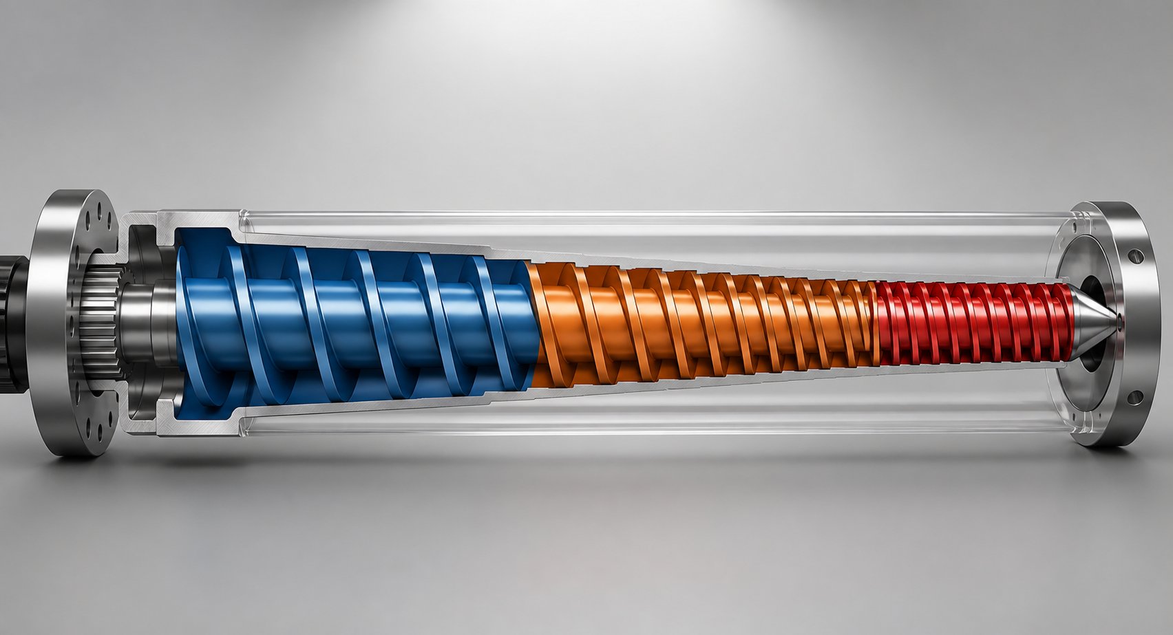
Picture the inside of a working barrel during screw extrusion. Solid pellets enter at one end, and a uniform molten stream exits the other. That transformation does not happen all at once. It unfolds progressively across three distinct functional zones engineered into the screw's geometry - each with a specific channel depth, a specific job, and a specific set of processing variables that determine whether the output is excellent or problematic.
Most suppliers ship a machine with a recommended screw and leave it at that. They rarely explain why the screw looks the way it does - why part of it is deep, why part of it tapers, and why part of it is shallow. Understanding these zones gives you a practical framework for diagnosing output problems, selecting the right screw for a new resin, and communicating intelligently with screw designers when standard configurations fall short.
- Feed Zone - deep, constant-depth channel for solids intake and conveying
- Compression (Transition) Zone - progressively shallower channel where melting occurs
- Metering Zone - shallow, constant-depth channel for melt homogenization and pressure generation
Feed Zone and Solids Conveying Mechanics
The feed zone is where the journey begins. It sits directly beneath the feed throat and typically occupies roughly 50% of the total screw length on a general-purpose design. Its channel - the space between the screw root and the flight tips - is at its deepest here, and that depth remains constant throughout the zone.
Why so deep? The screw needs to accept a large volume of loose, low-bulk-density pellets or granules and move them forward as a compacted solid bed. Gravity drops material from the hopper into this section, and the rotating flights push it along. But transport is not automatic. Solids conveying relies on a critical friction balance: the pellets must grip the barrel wall more than they grip the screw root. If the polymer slides freely against the barrel but sticks to the screw, conveying stalls. This is exactly why the feed throat is water-cooled - keeping the barrel entrance cool enough to maintain a high coefficient of friction against the pellets while preventing premature softening.
The processing variables that matter most in the feed zone are pellet geometry (shape, size, bulk density), barrel surface temperature at the feed opening, and screw speed. Inconsistent feed - whether from pellet bridging in the hopper, an overheated feed throat, or irregularly shaped regrind - will starve the downstream zones and produce the kind of output surging that no amount of downstream adjustment can fix.
Compression Zone and the Melting Process
As the solid bed moves forward, it enters the compression zone - sometimes called the transition zone. This section typically makes up about 25% of the screw length, and its defining feature is a gradually decreasing channel depth. Imagine the walls slowly closing in on the polymer as it travels.
This narrowing channel does several things simultaneously. It compacts the solid pellets tighter together, squeezing out trapped air that would otherwise cause voids or bubbles in the final product. It increases the pressure on the material, forcing it into intimate contact with the hot barrel wall where a thin melt film begins to form. And it dramatically increases shear forces as the gap between root and barrel shrinks, generating frictional heat within the polymer itself. As Allan Griff's extrusion manual explains, the compression zone depth "gets shallower, as if the walls were closing in on the plastic, and that builds pressure preventing the air between the particles from continuing down the barrel."
In many single screw extrusion machines, shear heating accounts for 60 to 80% of the total energy input required for melting - the barrel heaters contribute far less than most operators assume. The melting mechanism itself follows a well-studied pattern: a thin melt film forms against the hot barrel wall, the rotating screw scrapes this film off and collects it on the pushing side of the flight, and the remaining solid bed is continually exposed to fresh barrel surface for further melting.
The key processing variables here are compression ratio (the depth ratio between the feed and metering zones), the length of the transition, and barrel temperature set-points. A compression that is too aggressive can generate excessive pressure spikes and shear-induced degradation in heat-sensitive polymers. Too gentle, and pellets pass through unmelted.
The compression ratio - typically between 2:1 and 4:1 - defines how aggressively the screw compacts and melts the polymer. It is not a standalone spec; it must be paired with actual channel depths and the transition zone length to properly characterize a screw's melting behavior.
Metering Zone and Melt Delivery Consistency
By the time the polymer reaches the metering zone - the final section of a standard screw extruder - it should be fully or nearly fully molten. This zone returns to a constant channel depth, but one much shallower than the feed. A typical general-purpose screw might have a feed depth of 6 mm and a metering depth of 2 mm, reflecting a 3:1 compression ratio.
The metering zone is responsible for three things that directly determine product quality. First, it homogenizes the melt, ensuring uniform temperature and viscosity across the entire flow channel. Any residual unmelted particles or cool spots from incomplete melting upstream get worked out here through continued shear mixing. Second, it generates the stable, consistent pressure needed to push the melt through the breaker plate, screen pack, and die at a steady rate. Pressure fluctuations in the metering zone translate directly into dimensional variations in the extrudate - wall thickness changes in pipe, gauge inconsistencies in film, or weight variations in pelletizing. Third, the shallow channel and constant depth give this zone its name: it meters a predictable volumetric flow rate for a given screw speed, acting as the process's built-in flow regulator.
The variables that influence metering-zone performance are channel depth, screw speed (RPM), melt viscosity (which is temperature- and shear-rate-dependent), and the back pressure imposed by the downstream die and screen pack. Operators who chase higher output by simply increasing screw speed without considering metering-zone capacity often end up with poorly mixed melt and surging output - the metering section can only deliver what the upstream zones have properly prepared.
One modern refinement worth noting is the grooved feed section, found on many European-designed single screw extrusion machines. By machining axial or helical grooves into a water-cooled feed barrel liner, these systems dramatically improve solids conveying - especially for slippery, hard-to-feed polymers like HDPE. The trade-off is significant: because the grooved feed forces material forward so effectively, the screw design changes entirely. Feed zone depth decreases, metering zone depth increases, and in some cases the compression ratio approaches 1:1. A deeper metering channel, however, provides less shear mixing, so grooved-feed extruders typically require dedicated mixing elements or static mixers downstream to maintain melt quality.
These three zones - feed, compression, and metering - are not arbitrary labels. They represent a carefully engineered sequence of physical transformations that every polymer must undergo to emerge as a consistent, high-quality melt. The specific dimensions of each zone - channel depth, length, and taper - are what define a screw's geometry. And it is that geometry, more than any other single factor, that determines whether a screw extruder performs brilliantly or merely adequately with a given polymer.
Screw Geometry and Design Philosophy That Drives Performance
Two extrusion screws can look nearly identical on a shop floor - same diameter, same overall length, same polished steel finish. Install one and your HDPE pipe line runs flawlessly at 350 kg/h. Install the other and you get unmelted pellets in the extrudate, surging output, and a production manager on the phone. The difference? Geometry. The specific dimensional relationships built into an extrusion screw - its L/D ratio, compression ratio, flight depth profile, helix angle, channel width, and flight clearance - dictate everything from melting efficiency to melt temperature uniformity. Yet most equipment suppliers hand over a "general-purpose" screw and rarely explain why that particular geometry was chosen, or when it falls short.
This section breaks down those parameters in practical terms so you can evaluate whether a screw plastic extruder is properly configured for your specific polymer, output target, and quality standard.
L/D Ratio and Compression Ratio Explained
The length-to-diameter ratio (L/D) is the first number most engineers look at when sizing a single extruder screw. It expresses how much working length the screw provides relative to its bore size. A 90 mm screw with an effective length of 2,700 mm has a 30:1 L/D. A shorter version at 2,160 mm drops to 24:1.
Why does this matter? A longer L/D gives the polymer more residence time inside the barrel, which means more opportunity for heat transfer, melting, and mixing. As GS Extruder's screw parameter analysis notes, enhanced L/D ratios combined with optimized thermal gradients facilitate superior polymer blending and plasticization. The trade-off is real, though: longer screws demand more drive torque, tighter manufacturing tolerances, and greater sensitivity to shaft deflection - particularly on smaller-diameter machines where a stress analysis becomes essential.
Here is a practical framework for L/D selection:
- 20:1 to 24:1 - Suitable for thermally sensitive polymers (rigid PVC, certain fluoropolymers) where minimizing residence time prevents degradation. Also adequate for pre-compounded pellets that require less melting energy.
- 24:1 to 28:1 - The most common range for general-purpose extrusion of polyolefins, styrenics, and engineering thermoplastics.
- 30:1 to 36:1 - Used when higher throughput, intensive mixing, or processing of powder feedstocks demand extended working length. Also common on grooved-feed extruders and barrier-screw designs.
Compression ratio, the second fundamental parameter, compares the volume of the first full flight in the feed section to the last flight in the metering section. On a constant-pitch screw - which is the most common type - this simplifies to the ratio of feed-zone channel depth to metering-zone channel depth. A screw with a 6 mm feed depth and a 2 mm metering depth has a 3:1 compression ratio.
Different polymers demand different compression ratios because of their distinct melting behaviors and thermal sensitivities. The table below, drawn from published processing data, illustrates the range:
| Polymer | Typical Compression Ratio | Why This Range? |
|---|---|---|
| Polyethylene (PE) | 3.0 - 4.0 | Semi-crystalline; needs aggressive compression to melt efficiently |
| Polypropylene (PP) | 2.5 - 4.0 | Similar crystalline melting behavior to PE; broad processing window |
| Polystyrene (PS) | 2.0 - 4.0 | Amorphous; melts gradually over a wide temperature range |
| Rigid PVC (granules) | 2.0 - 3.0 | Heat-sensitive; lower compression reduces shear-induced degradation |
| ABS | 1.6 - 2.5 | Low compression protects rubber phase from excessive shear |
| Polycarbonate (PC) | 2.5 - 3.0 | High melt viscosity; moderate compression avoids excessive melt temperature |
| Polyamide 66 (PA66) | 3.7 | Sharp crystalline melting point demands precise compression design |
Notice the pattern: heat-sensitive and amorphous polymers tolerate - and often require - lower compression, while semi-crystalline resins with sharp melting points benefit from higher ratios that deliver more aggressive compaction and shear energy. Choosing the wrong compression ratio is one of the most common yet least discussed causes of poor melt quality on single screw lines.
Two other geometric parameters deserve attention alongside L/D and compression ratio. The helix angle - the angle between the screw flight and a plane perpendicular to the screw axis - influences both conveying efficiency and plasticization time. A 17°41' angle is the standard for most metering-section designs, though the optimal feed-section angle varies: roughly 30° for powder feedstocks, around 17° for cylindrical pellets, and approximately 15° for square-cut granules. Flight clearance, the gap between the outermost edge of the flight and the barrel bore, typically falls between 0.1 and 0.6 mm. Too tight, and the screw generates excessive frictional heat and is expensive to manufacture. Too loose, and polymer leaks backward over the flights, reducing pumping efficiency, increasing melt temperature through recirculation, and - in extreme wear cases - making stable extrusion nearly impossible.
Barrier Flights and High-Performance Screw Designs
A conventional three-zone screw works well for many applications, but it has a fundamental limitation: the solid bed and melt pool share the same channel. This co-mingling can cause solid-bed breakup, where chunks of unmelted polymer break free, float through the melt, and end up as defects in the finished product. Barrier screws solve this problem with an elegantly simple modification.
A barrier screw introduces a secondary flight - the barrier flight - that runs parallel to the main flight through most of the compression zone. This creates two distinct channels: one for the solid bed and one for the melt. The barrier flight has a slightly larger clearance to the barrel wall than the primary flight - enough for molten polymer to flow from the solids channel into the melt channel, but tight enough (typically around 1.5 mm) to block unmelted pellets from crossing over. As Allan Griff explains, the pellets stay in their main channel but are drained of excess melt and, as a result, generate more frictional heat as they rub against one another - making melting more efficient per revolution.
The practical result? Barrier-flight screw extruders can achieve 10-20% higher output at the same RPM compared to a conventional design, with more uniform melt temperature and fewer unmelted particles reaching the die. This makes them particularly valuable for processing semi-crystalline polymers like HDPE and PP, which have sharp melting points and are prone to solid-bed breakup on standard screws.
Mixing Elements and Additive Dispersion
Even a perfectly melted polymer stream is not necessarily a well-mixed one. Color concentrates, UV stabilizers, processing aids, and fillers all need to be evenly distributed throughout the melt. Standard screw flights provide only limited mixing action - the polymer moves forward in relatively orderly streamlines. Breaking up those streamlines requires dedicated mixing elements, and two distinct types serve different purposes:
- Dispersive mixing subjects the melt to high shear stress, physically breaking down agglomerates of pigment or additive particles into smaller domains. The Maddock (or LeRoy) mixer is the classic dispersive element - a section roughly two diameters long featuring paired inlet and outlet flutes separated by a barrier ridge. Melt enters the inlet flutes, is forced over the barrier ridge at a controlled clearance of about 0.5 to 0.75 mm, and exits through the outlets. Unmelted particles and pigment clumps cannot pass over whole; they are sheared and flattened until they finally cross as homogeneous melt.
- Distributive mixing spreads already-dispersed particles evenly throughout the melt volume without necessarily applying high shear. Pin-mixing elements - rings of studs projecting from the screw root - are the simplest example. They work like rocks in a stream, disrupting laminar flow patterns and repeatedly reorienting melt layers so that minor components become uniformly distributed.
In practice, the best extrusion screw designs combine both types. A common high-performance configuration pairs a barrier section in the compression zone with a Maddock mixer near the screw tip, providing both efficient melting and thorough melt homogenization. Pin-mixing elements are then added in the last quarter of the screw to polish color dispersion and thermal uniformity.
| Screw Design Feature | Type of Mixing | Processing Benefit | Best Suited For |
|---|---|---|---|
| Barrier Flights | Melting enhancement (not a mixer per se) | Separates solid bed from melt pool; increases melting rate per RPM; reduces unmelts | Semi-crystalline polymers (HDPE, PP, PET); high-output lines |
| Maddock (LeRoy) Mixer | Dispersive | Breaks down agglomerates; eliminates unmelted particles; improves thermal uniformity | Color-critical applications; resins prone to gels or unmelts |
| Pin-Mixing Elements | Distributive | Reorients melt layers; spreads additives and colorants evenly without excessive shear | Color concentrate letdown; additive blending; shear-sensitive polymers |
| Pineapple Mixer | Distributive + mild dispersive | Combines flow splitting with moderate shear; good general-purpose mixing | Blown film; pipe; profile extrusion with moderate mixing demands |
| Wave / Energy Transfer Screw | Distributive | Oscillating channel depths force melt back and forth across barrier; excellent thermal homogeneity | Thick-wall pipe; sheet extrusion where melt temperature uniformity is paramount |
The takeaway for anyone evaluating or specifying screw extruders is straightforward: geometry is not a detail - it is the design decision that determines whether your line produces premium-quality output or marginal product. A general-purpose 3:1 compression screw with no mixing section will run PE pipe acceptably, but it will not deliver the color consistency needed for a cosmetic-grade cap, the melt uniformity required for optical-quality sheet, or the throughput a high-speed blown-film line demands. Matching screw geometry to your polymer and your product is the single highest-leverage engineering choice in the entire extrusion process.
Geometry, however, does not exist in isolation. The same screw design that excels with polypropylene may underperform or even damage a heat-sensitive PVC compound. The real skill lies in matching screw and barrel configuration to the specific polymer family - a subject that draws on material science as much as mechanical engineering.
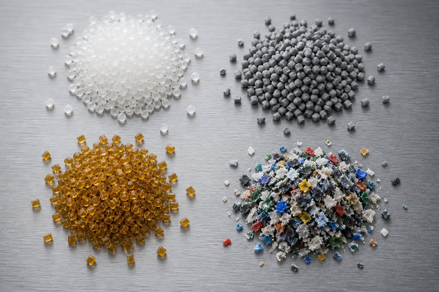
Matching Polymers to the Right Single Screw Configuration
A screw geometry that delivers flawless HDPE pipe can destroy a PVC compound in minutes. A barrel liner that shrugs off polyolefins for years will pit and corrode within months if you switch to chlorinated feedstock. The polymer you process is not a secondary consideration - it is the primary design driver for every extruder for polymer processing. Yet most equipment purchases treat the screw and barrel as fixed, off-the-shelf hardware, independent of material choice. That disconnect is where performance problems, premature wear, and costly scrap originate.
The framework below maps each major polymer family to the screw and barrel configuration it demands. Use it as a starting point for specifying new equipment or evaluating whether your existing polymer extruder machine is actually optimized for what you are running.
| Polymer Family | Recommended L/D Range | Compression Ratio | Special Barrel/Screw Requirements |
|---|---|---|---|
| Polyolefins (PE, PP) | 24:1 - 30:1 | 2.5:1 - 4.0:1 | General-purpose nitrided barrel; barrier flights recommended for HDPE; standard nitrided screw adequate for unfilled grades |
| Styrenics (PS, ABS) | 24:1 - 28:1 | 2.0:1 - 3.0:1 (ABS: 1.6:1 - 2.5:1) | Moderate compression to protect rubber phase in ABS; distributive mixing for color-critical work; standard barrel liner |
| PVC (rigid and flexible) | 20:1 - 24:1 | 1.5:1 - 2.5:1 | Corrosion-resistant barrel liner (bimetallic or stainless); chrome-plated or coated screw; degassing capability; precise temperature control |
| Engineering Plastics (PC, PA, PET) | 28:1 - 36:1 | 2.5:1 - 3.7:1 | Pre-drying essential for PA and PET; vented barrel for moisture removal; hardened/wear-resistant barrel for glass-filled grades; longer L/D for thorough melting |
| Recycled / Regrind Materials | 26:1 - 33:1 | 2.5:1 - 3.5:1 | Vented barrel for volatiles; wear-resistant construction for contamination; robust feed zone design; mixing elements for melt homogeneity |
Polyolefins, Styrenics, and General-Purpose Configurations
Polyolefins - polyethylene and polypropylene - are the most forgiving polymer family to extrude, which is precisely why they account for the majority of single screw extrusion worldwide. Both are semi-crystalline with relatively sharp melting points (around 130 °C for HDPE, 165 °C for PP), and both tolerate a broad processing window without degradation risk. A standard general-purpose screw with a 3:1 compression ratio works acceptably for most PE and PP applications. For high-output film and pipe lines, a barrier-flight screw design improves melting efficiency by separating the solid bed from the melt pool - critical when pushing a pp extruder to maximum throughput.
A nitrided steel screw and standard barrel liner handle unfilled polyolefins well, often lasting several years before measurable wear develops. The barrel and screw demands increase significantly, however, when fillers enter the picture. Calcium carbonate-filled PP or talc-reinforced compounds accelerate abrasive wear on flight tips and barrel bore, making bimetallic barrel liners and hardfaced screw flights a worthwhile upgrade for filled polyolefin production.
Styrenics - polystyrene and ABS - are amorphous, meaning they soften gradually over a wide temperature range rather than melting sharply. This makes them somewhat easier to plasticize but also more sensitive to excessive shear, especially ABS. The rubber phase dispersed throughout ABS can degrade under high-shear conditions, so these polymers favor a lower compression ratio (typically 1.6:1 to 2.5:1) and gentler transition zones. For color-critical PS and ABS applications, adding distributive mixing elements - pin mixers or pineapple-type sections - near the screw tip dramatically improves pigment distribution without introducing the shear levels that damage rubber domains.
PVC, Engineering Plastics, and Specialty Polymers
PVC stands alone among commodity polymers for the engineering challenges it presents. It is intensely heat-sensitive: push the melt temperature above approximately 205 °C and the molecular chains begin decomposing, releasing hydrochloric acid (HCl) gas. That HCl does not just degrade the product - it actively corrodes the metal surfaces of screws and barrels from the inside out. This dual threat - thermal degradation and chemical attack - demands a fundamentally different machine configuration than what you would run for polyolefins.
A screw extruder processing PVC requires a low compression ratio (1.5:1 to 2.5:1) to minimize shear heating, a shorter L/D (20:1 to 24:1) to reduce residence time, and barrel and screw materials built to resist chlorine-based corrosion. Stainless steel or nickel-alloy barrel liners, chrome-plated or PVD-coated screws, and precise multi-zone temperature control are all standard requirements, not optional upgrades. Degassing capability is equally essential - vented barrels allow HCl vapor and moisture to escape before they can damage the product or equipment.
Engineering plastics present a different set of demands. Polycarbonate (PC), polyamide (PA/nylon), and polyethylene terephthalate (PET) all process at substantially higher temperatures than commodity resins - barrel temperatures routinely exceed 270 °C for PC and can reach 300 °C for certain nylon grades. PA and PET are hygroscopic, meaning they absorb atmospheric moisture that, if not removed before processing, causes hydrolytic degradation: chain scission that destroys mechanical properties and produces a foamy, splay-marked extrudate. Pre-drying to moisture levels below 0.02% (for PET) or 0.1% (for PA) is mandatory, and vented-barrel designs provide an additional safety margin.
When engineering plastics carry glass-fiber reinforcement - as glass-fiber-filled PA frequently does - the abrasion equation changes entirely. Glass fibers are harder than standard barrel and screw steels. A polyester extruder or PA line running 30% glass fill will grind through a nitrided screw in a fraction of the time an unfilled resin would. Bimetallic barrels with tungsten-carbide or boron-alloy liners and hardfaced screw flights become essential for any economically viable service life.
Processing Recycled and Regrind Materials on Single Screw Lines
Recycling is no longer a niche application - it is a central strategic priority across the plastics industry. Single screw extrusion handles a growing share of regrind and post-consumer recycled (PCR) material, but the processing challenges are fundamentally different from running virgin pellets.
The first issue is feedstock inconsistency. Regrind particles are irregularly shaped - flakes, shreds, chunks - with lower bulk density than uniform virgin pellets. Research at the University of Stuttgart demonstrated that regrind's reduced bulk density lowers the specific throughput (output per screw revolution) on grooved-feed extruders, which in turn raises melt temperature and shrinks the usable processing window. Their work showed that a novel compression zone in the feed section - using a larger filling diameter and a grooved, conically tapered transition - can align regrind throughput with virgin material throughput, effectively restoring the process window that regrind typically destroys.
Beyond feed behavior, recycled feedstock introduces contaminants - paper labels, adhesive residues, mixed polymer fractions, and variable moisture content. These demand several equipment adaptations:
- Vented barrels to extract moisture and volatile contaminants before they cause splay or voids
- Heavy-duty screen changers with continuous or slide-plate designs so contaminated screen packs can be swapped without stopping the line
- Wear-resistant barrel liners and screw flights because contaminants - grit, metal fragments, mineral residues - accelerate abrasive wear far beyond what virgin resin produces
- Mixing sections (Maddock or pin-type) to homogenize variable melt viscosity caused by mixed polymer batches or inconsistent melt flow index
Screw geometry for regrind processing typically favors a moderate compression ratio (2.5:1 to 3.5:1) and an L/D in the 26:1 to 33:1 range - long enough to provide adequate melting and mixing residence time for inconsistent feedstock, but not so aggressive in compression that irregularly shaped particles jam or bridge in the transition zone. Some processors add a secondary grooved-feed section or a crammer feeder to force low-bulk-density flake into the screw channel reliably.
The practical takeaway is this: the polymer dictates the machine. Running the wrong screw geometry, the wrong barrel metallurgy, or the wrong compression ratio for your specific resin family does not just reduce performance - it can accelerate equipment wear, degrade product quality, and in the case of PVC, chemically attack the very components you depend on. Matching the polymer extruder to its feedstock is not an optimization step. It is a prerequisite for viable production.
Material selection, of course, only tells half the story. The same polymer processed on the same screw can produce wildly different products depending on what sits downstream of the die - and each end-product application places its own unique demands on the extrusion line as a whole.
End-Product Applications and the Full Plastic Extrusion Machine Ecosystem
A single screw plastic extruder does not operate in isolation. What it produces - pipe, film, sheet, profiles, coated wire - depends entirely on the die configuration and the downstream equipment that follows it. Most buyers focus exclusively on the extruder itself. That is like choosing a car engine without considering the drivetrain, suspension, or wheels. The downstream line determines whether a hot, shapeless melt becomes a precision product you can sell.
Each application category below pairs the extruder with the specific downstream stations it requires. You will notice that every product type also places distinct wear demands on the screw and barrel - a detail most suppliers gloss over but one that directly impacts operating cost and uptime.
Pipe, Tubing, and Profile Extrusion Lines
Pipe and tubing represent the largest single application for single screw extrusion worldwide, covering everything from PVC drainage systems and HDPE water mains to medical-grade silicone tubing. A plastic tube extruder feeds molten polymer through an annular die to form a hollow cross-section. From there, the downstream ecosystem takes over:
- Pipe and tubing lines: Vacuum calibration tank (locks the outside diameter and roundness against a sizing sleeve), spray or immersion cooling tanks (solidify the wall), caterpillar haul-off (pulls the product at a controlled, constant speed that determines wall thickness), planetary or chipless cutter (cuts to length without deforming the pipe end), and stacking or coiling equipment.
- Profile and decking lines: A plastic profile extrusion machine uses a shaped die that matches the target cross-section - window frames, deck boards, cable trays. Downstream stations include calibration blocks or sizing tables that hold the complex geometry rigid during cooling, followed by cooling baths, belt haul-offs, and saws or flying cutters. Modular plastic profile extruders often integrate co-extrusion capability for cap layers or color stripes.
PVC pipe production is particularly harsh on equipment. The hydrochloric acid released during processing corrodes standard screw and barrel surfaces, while mineral-filled PVC compounds add abrasive wear on top of the chemical attack. Producers in this sector frequently source replacement screw-and-barrel assemblies matched to their specific machine model and application to maintain tight dimensional tolerances. NANHAIYA's single screw barrel solutions, for example, serve pipe, film, and recycling producers by manufacturing custom replacements based on machine models, drawings, samples, or measured dimensions.
Film, Sheet, and Coating Applications
Film and sheet extrusion demand the highest melt quality of any application - because every imperfection becomes visible. The downstream configurations differ significantly between formats:
- Blown film lines: The extruder feeds an annular die that forms a thin-walled tube of melt. Air pressure inflates this tube into a bubble, an air ring cools the bubble's surface, a collapsing frame flattens it, nip rolls pull it upward, and a winder collects the finished film. Line speeds typically reach 100-200 m/min, and melt uniformity directly governs gauge consistency across the bubble circumference.
- Cast film and sheet lines: A flat die spreads the melt into a wide web. A polished chill roll rapidly quenches the film for optical clarity, edge trimmers clean the margins, a thickness gauge provides real-time feedback, and a winder or stacker collects the output. Cast film lines can exceed 365 m/min, making even minor melt inconsistencies visible as gauge bands or surface defects.
- Wire and cable coating: A crosshead die wraps molten polymer concentrically around a moving conductor. Downstream stations include a cooling trough, a spark tester (to detect coating pinholes), a diameter gauge, a capstan, and a take-up reel. Concentricity depends on both die alignment and rock-steady melt delivery from the extruder.
High-output film lines push screws and barrels hard. Barrier-flight designs and long L/D ratios (30:1 or greater) are standard because the plastic extrusion machines in this sector must deliver gel-free, thermally uniform melt at high throughput rates - any shortfall shows up immediately as film defects.
Pelletizing, Compounding, and Recycling Lines
Not every extruder for plastic makes a finished product. Pelletizing and compounding lines use the extruder to melt, mix, and re-form polymer into uniform pellets for downstream processors. The typical downstream chain includes a die plate with multiple strand holes, a water bath or underwater pelletizer, a centrifugal dryer, and a pellet classifier.
- Strand pelletizing: Multiple melt strands exit the die, pass through a water bath to solidify, and feed into a strand cutter that chops them into uniform pellets. Simple and cost-effective for most commodity resins.
- Underwater pelletizing: Melt exits through a die face submerged in water; rotating knives cut pellets immediately, which are then carried by water flow to a dryer. Preferred for high-throughput and sticky materials.
- Recycling lines: Regrind and post-consumer flake are melted, filtered through continuous screen changers, degassed via vented barrels, and pelletized for resale. Contamination accelerates both abrasive and corrosive wear on the screw and barrel far faster than virgin resin processing.
Pelletizing applications subject screw flights to intense abrasive wear - especially when processing filled compounds or contaminated recyclate. Recycling lines face the additional challenge of variable feedstock, which can shift viscosity and filler content from batch to batch. In both cases, operators benefit from sourcing custom or replacement screw-and-barrel assemblies engineered for their specific machine model and wear conditions, rather than relying solely on generic OEM replacements.
Across every application - whether you are running pipe, blown film, wire coating, or recycled pelletizing - a common reality emerges: the screw and barrel absorb the punishment, and their condition directly determines how long your line stays productive. Choosing the right extruder for a given application is one decision. Keeping that extruder performing at its best over thousands of operating hours is another - and it starts with understanding the selection criteria that separate a well-matched machine from an expensive compromise.
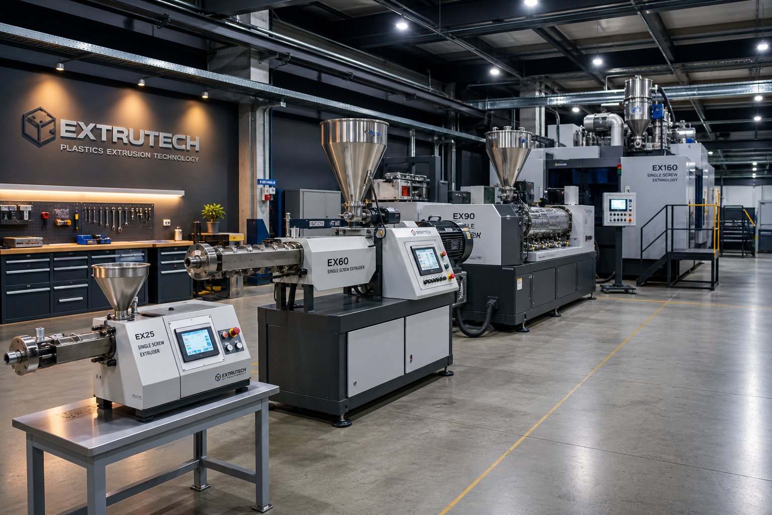
How to Choose the Right Single Screw Extruder Machine for Your Operation
Selecting a plastic extruder machine sounds straightforward until you realize that no two extrusion operations share identical requirements. Output targets, polymer types, product tolerances, floor space, electrical infrastructure, and budget all interact - and optimizing one factor often means compromising another. The suppliers quoting you equipment have a financial incentive to sell a specific model. Your job is to evaluate the full picture before signing a purchase order.
The checklist below consolidates the critical selection criteria into a single reference. Print it, share it with your engineering team, and use it to pressure-test every proposal you receive.
| Selection Criterion | Key Questions to Ask | Impact on Performance / Cost |
|---|---|---|
| Required Output (kg/h) | What is your target throughput at steady-state? What is the maximum you may need in 3-5 years? | Undersizing limits growth; oversizing wastes capital and energy running below optimal screw speed |
| Screw Diameter (mm) | Does the diameter deliver your target output within acceptable peripheral speed limits for your polymer? | Directly determines throughput capacity, shear rate, and residence time |
| L/D Ratio | Does the screw length provide adequate melting, mixing, and homogenization for your resin? | Too short reduces melt quality; too long increases residence time, energy cost, and risk of thermal degradation |
| Drive Power (kW) | Is the motor rated for the torque and speed range your polymer and output target demand? | Underpowered drives limit throughput; oversized motors waste capital but provide headroom for harder-to-process materials |
| Material Compatibility | Are the screw geometry, barrel metallurgy, and temperature control range matched to your polymer family? | Mismatched configuration causes degradation, excessive wear, poor melt quality, and scrap |
| Downstream Integration | Does the extruder's output rate and melt quality match your die, calibration, cooling, and haul-off equipment? | Bottlenecks anywhere downstream negate an oversized extruder investment |
| Energy Efficiency | What drive type, heater technology, and insulation does the machine use? | Operating cost per kilogram of output; payback period on premium efficiency features |
| Budget and Total Cost of Ownership | What is the acquisition cost vs. projected operating cost over 5-10 years? | Lower plastic extruder machine price does not always mean lower lifetime cost |
Output, Screw Diameter, and Drive Power Sizing
Start with the end goal: how many kilograms per hour does your line need to produce? That number - not brand preference, not catalog availability - drives the first sizing decision. Screw diameter is the primary determinant of maximum throughput, but the relationship is not linear. A 60 mm screw does not produce exactly half the output of a 120 mm screw. Output scales roughly with the square of the diameter, so doubling the bore roughly quadruples capacity.
Here is where most buyers make their first mistake. They pick the diameter that barely meets today's output target, leaving zero headroom for future products, faster line speeds, or material changes. A better approach is to size the industrial extruder machine for roughly 70-80% utilization at your target throughput. This keeps the screw running at moderate RPM, which reduces shear heating, lowers wear rates, and extends component life.
Peripheral speed is the hidden constraint that separates a good sizing decision from a damaging one. Every polymer has a maximum tolerable peripheral speed - exceed it and you generate destructive frictional heat. As extrusion dimensioning research from SHS plus illustrates, a smaller-diameter extruder must spin faster to match the throughput of a larger one, pushing peripheral speeds higher. Polycarbonate, for instance, tolerates roughly 0.3 m/s. A 60 mm screw at 170 RPM would exceed that limit at approximately 0.5 m/s, while a 75 mm screw reaches the target output at 100 RPM with a peripheral speed of around 0.39 m/s - still above the safe threshold. In that scenario, neither machine is suitable without derating the output target or moving to a larger bore.
Drive power sizing follows a similar logic. The motor must deliver enough torque to rotate the screw against the resistance of the polymer being sheared and compressed. A useful starting estimate: calculate the thermal energy needed to raise your polymer from ambient temperature to processing temperature at your target throughput, then multiply by at least 2.5 to account for mechanical losses and pressure generation. A single screw extruder machine processing 200 kg/h of polycarbonate to 270 degrees C, for example, requires roughly 25 kW of thermal power - pointing toward a minimum drive rating of approximately 60-65 kW. Most manufacturers slightly oversize drives, which is generally preferable to undersizing. An oversized motor simply runs at partial load, while an undersized one becomes a hard ceiling on throughput.
Residence time adds another dimension to the sizing equation. Larger extruders have greater internal volume, meaning the polymer spends more time at elevated temperatures. For thermally sensitive resins like PVC or certain biopolymers, this extended exposure can trigger degradation. You can estimate average residence time by dividing the melt-filled volume of the extruder by the volumetric flow rate. If a system holds 3,000 cubic centimeters of melt and processes at 100 kg/h with a melt density of approximately 1,000 kg/m cubed, the average residence time lands around 108 seconds. For high-temperature polymers, shorter is generally better - unless mixing demands require more time.
Energy Efficiency and Operating Cost Factors
The plastic extruder machine price on an invoice is a one-time event. Your electricity bill arrives every month for the next decade. Energy consumption per kilogram of output is where the real cost of ownership lives, and it is the factor most buyers evaluate least rigorously.
Three technology choices have the greatest impact on energy efficiency:
- Drive system - AC servo vs. conventional DC motors: Modern AC servo drives with variable frequency control deliver 15-30% energy savings compared to older DC motor and SCR drive combinations. They achieve this through higher motor efficiency at partial loads, precise speed control that eliminates overshoot, and regenerative braking capability that feeds energy back during deceleration. For a single screw extruder machine running 8,000 hours per year, even a 20% reduction in drive energy can translate to thousands of dollars annually - often paying back the premium within 18-24 months.
- Heater technology - ceramic vs. mica bands: Ceramic band heaters insulate the barrel far more effectively than traditional mica heaters, reducing radiated heat loss by up to 50%. They also respond faster to temperature changes, improving zone control stability. The upfront cost is roughly double that of mica bands, but the energy savings and improved temperature precision make ceramic heaters the standard recommendation for any new machine purchase or heater replacement cycle.
- Barrel insulation blankets: Even with ceramic heaters, a bare barrel radiates significant thermal energy into the plant environment. Insulation blankets - typically fiberglass or aerogel wraps - can reduce barrel heat loss by 25-40%. They are inexpensive, easy to install, and deliver measurable energy savings from day one. As Coperion's energy efficiency analysis confirms, changes to barrel heating and insulation consistently provide optimization potential, contributing to the 8-14% average energy reductions achieved through modernization packages.
Beyond these three, do not overlook the screw itself as an energy variable. A worn screw with excessive flight clearance leaks polymer backward over the flights, forcing the motor to work harder to maintain output. The result is higher specific energy consumption (kWh per kg) without any increase in throughput - essentially paying more electricity to produce the same amount of product. Keeping the screw and barrel in specification is not just a quality measure; it is an energy efficiency measure.
New vs Used Equipment and Budget Considerations
Budget constraints are real, and used single screw extruders can offer legitimate value - provided you know exactly what you are buying. A well-maintained, five-year-old machine from a reputable manufacturer can deliver 80-90% of the performance of a new unit at 40-60% of the cost. The danger lies in purchasing a machine with hidden wear or outdated technology that turns the apparent savings into a money pit of repairs, downtime, and scrap.
If you are evaluating used equipment, treat the inspection process with the same rigor you would apply to buying a used aircraft engine. A structured approach based on industry inspection best practices should cover five areas:
- Visual and physical inspection: Check for cracks, rust, fluid leaks, damaged wiring, worn hoses, and missing safety guards. Corrosion on the barrel exterior can indicate internal problems. Examine the feed throat for scoring that suggests pellet bridging or overheating history.
- Documentation review: Request the machine's operating hours, maintenance records, previous polymers processed, and any rebuild history. A machine that ran abrasive glass-filled PA for 30,000 hours has a very different remaining life than one that processed unfilled PE. If no maintenance records exist, consider that a red flag.
- Mechanical and functional testing: Power up the machine, listen for abnormal noises or vibration from the gearbox and thrust bearing, verify temperature controllers reach and hold set-points accurately, and check that the screw rotates smoothly without axial play. Measure the barrel bore diameter at multiple points and compare against the original specification to quantify wear.
- Screw and barrel wear measurement: This is the most important step. Use bore gauges to measure the barrel inner diameter at the feed, compression, and metering zones. Check the screw's flight outside diameter with a micrometer. Any clearance exceeding the manufacturer's wear limit - typically 0.1 to 0.15 mm beyond nominal per side - means a replacement screw and barrel are needed immediately, and that cost must be factored into the purchase price.
- Trial run: If possible, run a short extrusion trial with your intended polymer. Inspect the output for dimensional consistency, surface quality, and any signs of surging, gels, or discoloration. A trial run reveals problems that static inspection cannot.
The true cost of a used single screw extruder is not its purchase price - it is the purchase price plus the cost of every component that needs replacement or repair to bring performance back to specification.
For operations with tighter budgets, a practical middle ground exists: purchase a used machine frame, gearbox, and motor - the components that retain value longest - and invest in new screws, barrels, heaters, and controls. This hybrid approach can deliver near-new processing performance at a fraction of the all-new plastic extruder machine price, provided the mechanical foundation is sound.
Whichever path you choose - new, used, or hybrid - the selection process should produce a machine that matches your polymer, your output target, your energy cost structure, and your downstream line. A well-chosen extruder runs efficiently for years. A poorly chosen one announces itself through daily problems that erode margins and frustrate operators - the kind of problems that follow predictable patterns and, fortunately, respond to systematic troubleshooting.
Troubleshooting Common Single Screw Extrusion Problems
Every plastic single screw extruder will eventually misbehave. The line that ran perfectly yesterday starts surging today. A surface defect appears that was not there last week. Output drops for no apparent reason. The instinct - and it is almost universal among operators - is to start adjusting temperatures, speeds, and pressures simultaneously. That impulse makes things worse. Effective troubleshooting changes one variable at a time, waits 15-20 minutes for the machine to reach a new steady state, and evaluates the result before touching anything else.
The table below consolidates the most frequent problems on extruders machines into a quick-reference diagnostic tool. Keep it posted near your control panel. We will unpack the critical ones in detail below.
| Problem | Likely Root Causes | Corrective Actions |
|---|---|---|
| Output surging (pulsing flow) | Feed throat overheating; inconsistent pellet size or bulk density; worn screw flights reducing conveying efficiency; bridging in hopper | Verify feed throat cooling water is active and cold; check for pellet bridging; reduce Zone 1 temperature; measure screw flight clearance |
| Melt fracture / sharkskin | Shear stress at die wall exceeds polymer's critical limit; die temperature too low; extrusion speed too high | Increase die temperature 5-10 degrees C; reduce screw RPM or line speed; widen die gap slightly; consider adding a polymer processing aid (PPA) |
| Die drool (beard buildup) | Low molecular weight polymer fractions separating at the die exit; cold die lips; rough die surface; incompatible additives | Polish die surfaces; ensure die face heaters are functioning; lower melt temperature slightly; adjust lubricant or additive formulation |
| Uneven wall thickness | Unstable melt pressure; uneven die gap; temperature variation across the die head; misaligned calibration tooling | Adjust die lip clearance for uniform distribution; stabilize barrel and die temperatures; check calibration sleeve alignment; inspect screw and barrel for wear |
| Overheating / thermal degradation | Excessive screw RPM generating shear heat; too-aggressive compression ratio for the resin; blocked cooling channels; too-high barrel set-points | Reduce screw speed first (shear heat dominates); verify cooling fans and channels are unobstructed; check for correct screw design; lower barrel temperatures only after addressing shear |
| Poor mixing / color streaks | Screw lacks mixing elements; dead spots in barrel or adapter trapping old material; low-quality masterbatch; insufficient back pressure | Upgrade to a screw with Maddock or pin-mixing sections; increase back pressure via finer screen pack; clean barrel and adapter thoroughly; use higher-quality masterbatch |
| Gels / unmelted particles | Insufficient residence time; low barrel temperatures in the transition zone; worn screw reducing compression; contaminated feedstock | Add a finer mesh screen pack to increase back pressure and residence time; raise transition zone temperatures incrementally; inspect screw compression zone for wear |
| Reduced output at same RPM | Screw and barrel wear increasing flight clearance; leakage flow over worn flights; degraded compression ratio | Pull screw and measure flight OD vs. barrel ID; replace screw and barrel if clearance exceeds OEM specification |
Surging, Melt Fracture, and Surface Defect Solutions
Surging - the rhythmic pulsing of melt pressure and output - is the single most reported problem on industrial extruder lines, and it almost always traces back to the feed zone. When the feed throat's water-cooling jacket is not maintaining adequate flow, pellets soften prematurely and stick to the screw root instead of sliding forward. This creates a slip-stick cycle: material stalls, pressure drops, then a slug breaks free, pressure spikes, and the cycle repeats. You will see it as periodic thickness variations in pipe walls, gauge bands in film, or weight fluctuations in pelletized output.
The fix starts at the source. Confirm that cooling water is flowing through the feed throat jacket - touch the housing; it should feel cool, not warm. If the water system checks out, reduce Zone 1 barrel temperature by 5-10 degrees C to discourage premature melting. Regrind and irregularly shaped feedstock are especially prone to surging because their lower bulk density starves the screw inconsistently. In those cases, a crammer feeder or force-feeding mechanism can stabilize intake.
Melt fracture presents differently - a rough, matte, or "sharkskin" texture on the extrudate surface. It occurs when the shear stress at the die wall exceeds the polymer melt's critical threshold, causing the outer layer to tear as it exits. Imagine squeezing toothpaste too hard from the tube - the surface distorts because the material at the wall cannot keep up with the material at the center.
Your corrective options work from gentlest to most disruptive. First, raise the die temperature by 5-10 degrees C. Warmer polymer has lower viscosity, which reduces wall shear stress. If thermal degradation limits prevent that increase, slow the line speed to reduce the shear rate. As a third option, slightly widen the die gap to lower the local velocity. Some processors also add fluoroelastomer-based polymer processing aids to the resin blend, which coat the die wall and reduce friction at the interface.
Die drool - that annoying buildup of degraded material on the die face that eventually breaks off and mars the product surface - shares some root causes with melt fracture but demands its own solutions. Low molecular weight polymer fractions and volatile additives tend to separate from the main melt stream under high shear at the die exit and accumulate on the die lips. Polishing the die surface reduces adhesion points. Ensuring the die face heaters maintain a uniform, adequate temperature prevents localized cooling that traps these fractions. In persistent cases, adjusting the lubricant ratio in the formulation or switching to a die with improved flow-channel geometry can eliminate the buildup entirely.
Temperature Imbalances and Thermal Degradation
When the extrudate exits the die smoking, discolored, or smelling burnt, the knee-jerk reaction is to lower the barrel heater set-points. More often than not, that changes nothing - because the majority of heat in a working extruder comes from mechanical shear, not the heater bands. On most single screw lines processing commodity polymers, viscous dissipation (frictional heat generated by the screw working the polymer) accounts for 60-80% of total energy input. The barrel heaters primarily initiate melting in the early zones and fine-tune the thermal profile downstream.
This means the most effective response to overheating is to reduce screw RPM. Slower rotation directly reduces the shear rate and, consequently, the internally generated heat. If the problem is chronic and does not respond to speed reduction, the screw's compression ratio may be too aggressive for the resin you are running. A 3.5:1 compression screw designed for HDPE, for instance, will generate excessive shear heat if you repurpose it for a heat-sensitive ABS or PVC compound.
Blocked or scaled cooling channels represent another hidden culprit. Mineral deposits from untreated cooling water gradually restrict flow through barrel cooling passages and fan ducts, degrading the temperature control system's ability to remove excess heat. Periodic flushing of cooling circuits should be standard practice - yet it rarely appears on maintenance schedules.
Poor mixing and color streaks, while less dramatic than thermal degradation, point to the same underlying issue: the melt is not homogeneous. Standard screw flights provide only limited mixing action - the polymer moves forward in orderly layers that do not readily interchange. Without dedicated mixing elements (Maddock mixers, pin sections, or pineapple mixers), pigment agglomerates and additive concentrations remain unevenly distributed. Increasing back pressure by installing a finer screen pack forces the melt through more resistance, improving mixing. But the most effective long-term solution is upgrading to a screw design that incorporates purpose-built mixing sections.
Recognizing Screw and Barrel Wear as a Root Cause
Here is the problem most operators overlook: many of the issues described above - surging, poor mixing, reduced output, rising melt temperature, dimensional inconsistency - can share a single hidden cause. Screw and barrel wear. It does not announce itself with a warning light or an alarm code. It develops gradually, over thousands of operating hours, and its symptoms mimic other problems so convincingly that operators chase temperature adjustments, screw speed changes, and resin substitutions for months before anyone thinks to pull the screw and measure.
As the barrel inner diameter increases from abrasive wear and the screw flight outer diameter decreases, the clearance between them grows. That widening gap allows polymer to leak backward over the flights instead of being pushed forward - a phenomenon called leakage flow or back-flow. The consequences cascade predictably:
- Reduced output at the same RPM - the screw pumps less effectively because material recirculates instead of advancing
- Rising melt temperature - leaked polymer gets sheared repeatedly, absorbing energy without contributing to throughput
- Increased energy consumption - the motor works harder to maintain the same output, driving up specific energy (kWh/kg)
- Dimensional instability - inconsistent pressure delivery causes wall thickness, gauge, or weight variations
- Poor melt quality - reduced compression in worn zones leaves unmelted particles and undermines mixing efficiency
A worn screw and barrel can silently increase your operating cost by 10-20% while simultaneously degrading product quality - and the symptoms are easily mistaken for process or material problems.
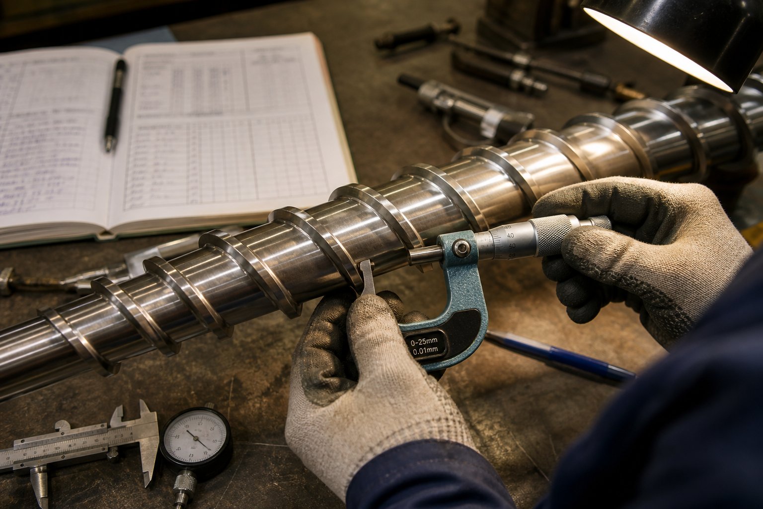
The diagnostic process is straightforward but requires pulling the screw. Use a bore gauge to measure the barrel inner diameter at the feed, compression, and metering zones, and compare readings against the original specification. Measure the screw flight outer diameter with a micrometer. Standard clearance on a new assembly is typically around 0.1 mm per side. If total clearance exceeds the OEM's wear limit - often 0.5 to 1.0 mm depending on machine size - the components are no longer capable of delivering consistent performance.
The real cost of running worn components extends beyond the obvious quality and output losses. A worn screw forces higher motor amperage to compensate for lost pumping efficiency, accelerating drive wear and increasing electricity costs. It also makes every other troubleshooting effort less effective - you cannot stabilize a process built on a leaking pump.
Recognizing wear as a root cause is the diagnostic breakthrough. Deciding what to do about it - when to repair, when to replace, and how to extend component life between change-outs - is the operational discipline that separates high-performing extrusion plants from ones that perpetually fight the same problems.
Maintenance Strategies and Knowing When to Replace Your Screw and Barrel
Diagnosing wear as a root cause is only half the battle. The other half - the half that separates reactive operations from profitable ones - is building a maintenance discipline that catches degradation early, extends component life systematically, and schedules replacements before quality and output force your hand. Most plastic extruder manufacturers ship a machine with a basic manual and little practical guidance on how to keep the screw and barrel performing at specification over years of production. What follows is the maintenance framework your supplier probably did not include.
Key Wear Indicators Every Operator Should Monitor
Wear inside a single screw plastic extruder is invisible from the outside. You cannot see the barrel bore widening or the screw flight tips eroding. What you can see are the downstream symptoms - and learning to read them accurately is the most valuable diagnostic skill an extrusion team can develop.
Three types of wear drive these symptoms. Adhesive wear occurs when screw flight surfaces and the barrel bore make direct metal-to-metal contact, locally welding and tearing at asperities - look for burrs or rolled edges on the trailing side of flight lands. Abrasive wear, the most common mechanism, results from hard filler particles, mineral additives, or contaminants grinding away metal during normal processing. Corrosive wear, driven by chemical attack from polymers like PVC that release hydrochloric acid at processing temperatures, gradually destroys the metal surface and leaves it vulnerable to accelerated mechanical erosion.
Monitor these indicators on a regular basis:
- Declining output at constant screw RPM - the earliest and most reliable sign that flight clearance has increased, allowing polymer to leak backward over the flights instead of advancing
- Rising melt temperature without changes to barrel set-points - leaked polymer gets sheared repeatedly, generating excess heat that shows up on your melt thermocouple readings
- Increasing motor amperage or specific energy consumption (kWh/kg) - the drive works harder to compensate for lost pumping efficiency, and your electricity bill reflects it
- Dimensional drift in the extrudate - wall thickness variations in pipe, gauge inconsistencies in film, or weight fluctuations in pellets that were not present when the screw and barrel were new
- More frequent process adjustments - operators gradually raising screw speed, tweaking temperatures, or tightening screen packs to maintain output that once held steady without intervention
- Visible scoring or galling on the screw flights when pulled for inspection - evidence of adhesive wear from metal-to-metal contact, often caused by misalignment or solids wedging
- Higher scrap rates - poor mixing, unmelted particles, or inconsistent melt delivery produce defective product that was not a problem six months ago
The critical insight from industry experience is that these changes are almost always incremental. As Glycon Corp.'s Jeff Kuhman notes, operators tend to make small compensating adjustments - a few more RPM here, a temperature bump there - and the changes go unnoticed until they dramatically impact part quality or productivity. By the time someone investigates the root cause, the screw and barrel may be well past their useful service window, and there is no quick fix unless spare components are already on the shelf.
Track the relationship between screw RPM, motor amperage, output rate, and melt temperature over time. When the same output requires progressively more speed and energy, wear is the most probable cause - even if no single measurement looks alarming in isolation.
Preventive Maintenance Schedules That Extend Equipment Life
Preventive maintenance for a single screw extruder is not complicated, but it does require discipline. The biggest obstacle is not technical - it is organizational. Pulling a screw for measurement means stopping a production line, and stopping production is never popular. Yet the cost of a planned four-hour inspection is a fraction of the cost of an unplanned multi-day shutdown triggered by catastrophic wear or a seized component.
A practical schedule should cover three tiers:
Daily / per-shift checks: Verify feed throat cooling water flow and temperature. Confirm that all barrel zone heaters are reaching set-point within normal time. Listen for unusual vibration or noise from the gearbox and thrust bearing - changes in sound pattern often precede mechanical failure. Record motor amperage and melt pressure at steady state. These take minutes and cost nothing, but they establish the baseline data that makes trend analysis possible.
Quarterly inspections (every 2,000-2,500 operating hours): Measure barrel bore diameter at the feed, compression, and metering zones using a telescoping bore gauge or laser micrometer. Measure screw flight outside diameter at corresponding locations with an outside micrometer. Compare both readings against the original specification and your previous measurements to track the rate of clearance increase. Check screw straightness and concentricity - a bent screw accelerates wear on one side of the barrel and causes periodic pressure fluctuations. Inspect heating elements and thermocouples for degradation. Flush cooling water circuits to prevent mineral scale buildup that restricts heat removal.
Annual deep inspections: Pull the screw completely and visually inspect every flight for scoring, hardfacing delamination, or corrosion pitting. Inspect the barrel bore with a bore light for scratches, pitting, or localized wear patterns that indicate misalignment. Check gearbox oil for metal particles (indicating gear or bearing wear). Verify machine alignment between the drive, gearbox, barrel, and die head - misalignment is one of the most common causes of premature adhesive wear on screws and barrels, and industry alignment specialists report that very few machines are found to be properly aligned when checked.
Beyond scheduled inspections, three operational practices have the greatest impact on extending equipment life:
- Correct material purging: Before shutdown, purge the current resin with a thermally stable material at reduced speed and temperature. As Davis-Standard's maintenance guidelines recommend, a systematic shutdown reduces operating speed at the end of a run, lowers temperature to a safe level, and replaces the process resin with a base resin blended with an antioxidant master batch. This prevents carbonized material from accumulating on screw and barrel surfaces during idle periods.
- Proper startup and heat soak: On restart, bring the barrel to a temperature lower than normal operating temperature and heat-soak until the polymer inside is completely molten before starting screw rotation. The higher viscosity at lower temperature creates scrubbing forces that assist with purging, while ensuring full melting prevents the screw from rotating against solid polymer - a direct cause of adhesive wear and potential screw damage.
- Contamination prevention: Install magnets and metal detectors on the feed system to intercept tramp metal before it enters the barrel. Foreign objects - bolts, grinder blades, tools - cause immediate, severe damage to screw flights and barrel bore surfaces. Equally important, ensure regrind streams are clean and free of non-polymer contaminants that accelerate abrasive wear.
When and How to Source Replacement Screw and Barrel Assemblies
At some point, maintenance reaches its practical limit. The clearance between screw flight and barrel bore has widened beyond what process adjustments can compensate for. Output has dropped measurably. Energy consumption per kilogram has risen. Product quality requires constant intervention to maintain. The question shifts from "can we keep running?" to "is continued operation more expensive than replacement?"
The answer is almost always yes - continued operation with badly worn components costs more than replacement. A clearance increase from 0.1 mm to 0.5 mm on a 90 mm single screw extruder can reduce output by 8-15% and increase specific energy consumption by 6-12%. Multiply those losses across thousands of operating hours, and the replacement assembly pays for itself quickly - often within a few months of installation.
You have three sourcing paths, each with trade-offs:
OEM replacement: Ordering directly from the original machine manufacturer guarantees dimensional compatibility and usually comes with engineering support. The trade-offs are higher cost and longer lead times - weeks to months depending on the manufacturer's backlog and geographic location. For common machine models, this remains the default choice for many operations.
Refurbishment: If the screw's base material remains structurally sound - no fatigue cracking on magnetic particle inspection, no significant root diameter loss - the screw can be ground down, re-hardfaced with new wear-resistant overlay, and re-ground to final dimensions. Refurbishment typically costs 40-60% of a new screw's price and restores 85-95% of original service life. Barrels can similarly be refurbished by boring out the worn liner and installing a new centrifugally cast bimetallic insert. This is an economically sound option when the core components are in good condition.
Third-party custom manufacturing: Replacement screw-and-barrel sets can be manufactured by specialized single screw extruder manufacturers and suppliers to match the original machine model - using engineering drawings, physical samples, or measured dimensions from the existing components. This approach often delivers shorter lead times and competitive pricing compared to OEM channels, particularly for older or discontinued machine models where the original manufacturer may no longer stock parts. NANHAIYA's single screw barrel solutions, for instance, serve pipe, film, sheet, pelletizing, and recycling producers by manufacturing custom-fit replacements based on machine models, drawings, samples, or direct dimensional measurement - giving operators a practical alternative when OEM lead times or costs are prohibitive.
Whichever sourcing path you choose, several factors determine whether the replacement actually delivers the performance improvement you are paying for:
- Material compatibility: Specify screw and barrel alloys matched to your polymer. A nitrided 4140 screw running glass-filled nylon will wear out in a fraction of the time a bimetallic CPM-grade or Stellite-overlaid screw would last. The cheapest replacement is almost never the most economical one over a 36-month operating window.
- Dimensional verification: Before installation, independently verify the new screw's straightness, concentricity, and flight dimensions against the specification. Slide the screw into the barrel and rotate by hand to confirm free movement without interference. Dimensional errors introduced during manufacturing will accelerate wear from day one.
- Machine alignment: A new screw and barrel installed in a misaligned machine will wear prematurely regardless of alloy quality. Check and correct the alignment between drive, gearbox, barrel, and die head before or during the installation.
- Documentation and baseline: Record all dimensions of the new components at installation - screw flight OD, barrel bore ID at each zone, total clearance. These become the baseline for future wear tracking and help you predict the next replacement window with reasonable accuracy.
The goal is not to eliminate wear - that is physically impossible in any machine where a metal screw rotates inside a metal barrel while processing abrasive, corrosive, or high-viscosity materials. The goal is to manage wear intelligently: monitor it consistently, extend component life through sound operating practices, and replace at the point where continued operation costs more than new parts. Processors who build this discipline into their operations spend less on maintenance, produce more consistent product, and avoid the unplanned shutdowns that turn a manageable expense into an emergency.
Frequently Asked Questions About Single Screw Plastic Extruders
1. What is the difference between a single screw and a twin screw extruder?
A single screw extruder uses one rotating screw inside a cylindrical barrel, offering simplicity, lower capital cost, and reliable performance for producing pipe, film, sheet, and profiles from clean, consistent thermoplastic feedstock. A twin screw extruder uses two intermeshing screws in a figure-eight barrel, delivering superior mixing, degassing, and the ability to process highly filled, contaminated, or reactive materials. Single screw machines suit most commodity and engineering polymer applications, while twin screw systems are preferred for compounding, reactive extrusion, and advanced recycling where intensive mixing is essential. The choice depends on your material complexity, mixing requirements, and budget.
2. How do I know when my extruder screw and barrel need replacement?
Key indicators include declining output at the same screw RPM, rising melt temperature without changes to barrel set-points, increasing motor amperage or specific energy consumption (kWh/kg), and dimensional drift in the extrudate such as wall thickness or gauge variations. Operators often compensate by gradually raising screw speed or adjusting temperatures, masking wear until quality drops sharply. The definitive check involves pulling the screw and measuring barrel bore diameter and screw flight outside diameter against original specifications. When total clearance exceeds the OEM wear limit - typically 0.5 to 1.0 mm depending on machine size - replacement becomes more cost-effective than continued operation. Suppliers like NANHAIYA manufacture custom-fit replacement screw-and-barrel assemblies based on machine models, drawings, or measured dimensions, offering a practical alternative to OEM channels.
3. What are the three zones of a single screw extruder and what do they do?
The three functional zones are the feed zone, compression (transition) zone, and metering zone. The feed zone features a deep, constant-depth channel that accepts solid pellets from the hopper and conveys them forward using friction between the material and the barrel wall. The compression zone has a progressively shallowing channel that compacts solids, squeezes out trapped air, and generates the shear heat responsible for 60-80% of the total melting energy. The metering zone uses a shallow, constant-depth channel to homogenize the melt, build stable pressure, and deliver a consistent volumetric flow rate to the die. Each zone's channel depth and length are engineered to match specific polymer melting behaviors, and mismatches lead to problems like unmelted particles, surging output, or thermal degradation.
4. What screw compression ratio should I use for different plastics?
Compression ratio - the feed zone channel depth divided by the metering zone channel depth - varies by polymer family. Semi-crystalline polyolefins like PE and PP process well at 2.5:1 to 4.0:1 because their sharp melting points benefit from aggressive compaction. Amorphous styrenics such as PS use 2.0:1 to 4.0:1, while ABS requires a gentler 1.6:1 to 2.5:1 to protect its rubber phase. Heat-sensitive PVC demands a low 1.5:1 to 2.5:1 ratio to minimize shear-induced degradation. Engineering plastics like PC typically use 2.5:1 to 3.0:1, and PA66 requires approximately 3.7:1 due to its sharp crystalline melting point. Choosing the wrong ratio is one of the most common yet overlooked causes of poor melt quality on single screw lines.
5. How can I improve the energy efficiency of my single screw extruder?
Three technology upgrades deliver the greatest energy savings. First, replacing conventional DC motors with AC servo drives can reduce drive energy consumption by 15-30% through higher partial-load efficiency, precise speed control, and regenerative braking. Second, upgrading from mica to ceramic band heaters cuts radiated heat loss by up to 50% while improving temperature response. Third, installing barrel insulation blankets reduces heat loss by 25-40% at minimal cost. Beyond equipment upgrades, maintaining screw and barrel clearance within specification is critical - worn components force the motor to work harder for the same output, silently increasing specific energy consumption by 6-12%. Together, these measures can reduce operating cost per kilogram significantly over the equipment's lifetime.
Written by
Nanhaiya Technical Team
Zhoushan Nanhaiya Plastic Machinery Co., Ltd.
The Nanhaiya technical team supports screw and barrel manufacturing projects through application review, technical communication, custom manufacturing coordination, and production and quality control.
Discuss Your Application
Related Articles
More insights on screw barrel technology and plastics processing.

What Nobody Tells You About Screw Barrel For Plastic Machine Design
Oct 10, 2026
Learn how screw barrel for plastic machine design affects melt quality, throughput, and wear life. Covers geometry, resin matching, troubleshooting, and sourcing.
Read Article
Single Screw Extruder for Sheet: Stop Guessing, Start Specifying
Oct 9, 2026
Learn how to specify a single screw extruder for sheet production. Covers screw geometry, resin-specific processing, troubleshooting, and maintenance best practices.
Read Article
PE Pipe Extruder Machine: What Datasheets Won't Tell You
Oct 9, 2026
Learn how a PE pipe extruder machine works, key specs explained, material grade selection, maintenance tips, and buyer guidance beyond the datasheet.
Read ArticleLooking for something else?
Search by material, symptom or product and jump straight to the relevant page.
These are navigation suggestions based on keyword matching — not a quotation, not a delivery commitment, and not a substitute for engineering review. Final specification is confirmed by our engineers against your drawings and processed material.
Need help with screw barrel selection?
Share your machine model, processed material and application. Our team can help with pricing and technical support.