

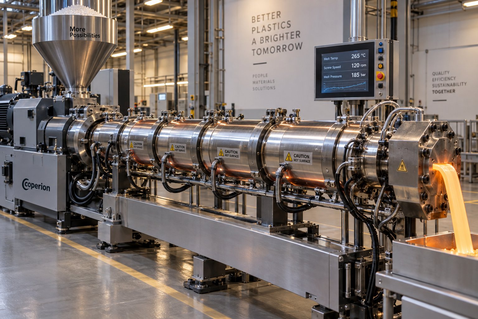
What Is Single Screw Extrusion and Why Does It Matter
Single screw extrusion is a continuous polymer processing method in which a single helical screw rotates inside a heated barrel to convey, melt, and pressurize plastic material, then push the homogeneous melt through a shaped die to form a finished product. It is the workhorse behind an enormous share of everyday plastic goods - from the water pipes beneath your house to the cling film in your kitchen drawer.
What Single Screw Extrusion Is and Why It Dominates Plastics Processing
Imagine a machine that takes raw plastic pellets at one end and delivers a perfectly shaped, continuous product at the other - all in a single, unbroken flow. That is exactly what a single screw extruder does, and it does it at scale. These machines account for the majority of plastics extrusion installations worldwide, producing pipe, film, sheet, profiles, and pellets across virtually every sector of the plastics industry. The global single screw extruder market is valued at roughly USD 1.3 billion in 2025 and is projected to reach USD 2.1 billion by 2035, growing at a CAGR of 5.4% - a clear signal that manufacturers continue to invest heavily in this technology.
Why does one machine type command such dominance? Three reasons stand out. First, the mechanical design is relatively simple: a single rotating screw inside a cylindrical barrel, driven by a motor and gearbox. Fewer moving parts mean fewer things that can break. Second, capital and maintenance costs run significantly lower than twin screw alternatives, making the technology accessible to small and mid-size processors as well as large-scale operations. Third, decades of proven reliability have built deep institutional knowledge - operators, engineers, and toolmakers around the world understand how to run, maintain, and optimize these systems.
You will find single screw extruders producing PP-R and HDPE pipes, blown and cast films, PVC profiles, multilayer sheets, and recycled pellets. Their versatility across this range of products, combined with their cost-effectiveness, is precisely why they remain the default choice when a processor needs to convert a pre-compounded resin into a finished or semi-finished product.
Core Components at a Glance
Before diving into the physics and process details in later sections, it helps to have a mental map of the hardware you are working with. Every single screw extruder is built around six essential components:
- Hopper - the funnel-shaped container mounted above the feed throat where raw material (pellets, powder, or regrind) enters the system by gravity.
- Barrel - a thick-walled, precision-bored steel cylinder that houses the screw and provides the controlled thermal environment for melting.
- Screw - the helical shaft at the heart of the process, responsible for conveying, compressing, melting, and metering the polymer. It is the single most critical component affecting output quality.
- Heater bands - electrical heating elements clamped around the barrel exterior, organized into individually controlled temperature zones to establish the correct thermal profile along the screw length.
- Drive system - a motor coupled to a gear reducer that delivers the torque and controlled rotational speed the screw needs to process the polymer efficiently.
- Die - the shaped orifice at the discharge end that forms the molten polymer into its final cross-sectional geometry, whether that is a tube, flat sheet, annular film bubble, or strand for pelletizing.
Each of these components influences every other. Change the screw geometry and you alter the melting behavior; adjust the heater band setpoints and you shift where along the barrel the polymer transitions from solid to melt; swap the die and you change the back pressure the screw must work against. Understanding these interactions - how the screw, barrel, thermal profile, and die function as a single interdependent system - is the key to optimizing both output quality and throughput.
That interdependence raises an obvious next question: what actually happens to the plastic as it travels from the hopper to the die? The answer lies in the physics of drag flow and pressure flow - two competing forces that govern every gram of material the extruder delivers.
How a Single Screw Extruder Actually Moves and Melts Plastic
Every screw extruder ever built operates on a deceptively simple principle: a rotating screw drags polymer forward, while the die at the end pushes back. The tug-of-war between these two forces - drag flow and pressure flow - determines exactly how much material exits the machine every second. Grasping this relationship is the single fastest way to move from "button pusher" to informed process engineer.
Drag Flow and Pressure Flow Explained in Plain Language
Picture the extrusion screw as a rotating helix inside a stationary barrel. Here is the counterintuitive part: from a physics standpoint, it does not matter whether you think of the screw turning inside the barrel or the barrel turning around the screw. Either way, the relative motion between the barrel wall and the screw surface creates a viscous drag that sweeps the polymer forward along the helical channel. This forward movement is called drag flow, and it is proportional to the screw diameter, channel depth, and rotational speed.
At the discharge end, the die acts as a restriction. The polymer must squeeze through a narrow opening, which creates back pressure. That back pressure drives a small reverse flow component inside the screw channel - polymer near the channel root actually creeps backward toward the feed end. This opposing component is called pressure flow.
The actual output of the extruder is always the difference between these two forces. A simplified drag-flow equation widely used by screw designers expresses this relationship as: 0.02258 x D2 x H x N, where D is screw diameter, H is channel depth, and N is rotational speed - all in English units. When head pressure is zero (open discharge), drag flow alone dictates output. In real production, pressure flow always subtracts from that maximum.
Net extruder output = Drag flow minus Pressure flow. Every operational decision you make - screw speed, die restriction, screen pack selection - shifts the balance between these two forces.
This is why doubling screw speed never doubles output in practice. The faster the single extruder screw turns, the more material it tries to push forward, but the higher die pressure that results simultaneously increases the backward pressure flow. Understanding this balance gives you real leverage when troubleshooting throughput issues or fine-tuning process conditions.
How Screw Rotation Translates Into Melt Delivery
With the drag-flow-versus-pressure-flow framework in mind, you can follow the polymer's full journey from hopper to die in a way that actually makes sense.
Solid pellets drop by gravity from the hopper into the feed throat, where the deep-channeled first section of the extrusion screw picks them up. Forward transport begins immediately - but it depends entirely on friction. The barrel wall must grip the polymer more firmly than the screw root does; otherwise the pellets would simply spin in place and never advance. This is why the feed section of the barrel is often water-cooled: keeping the barrel surface slightly tacky relative to the screw improves the frictional grip that initiates conveying.
As pellets ride the helical channel downstream, the channel depth gradually decreases. This compression squeezes the loosely packed pellets into a dense solid bed, expelling trapped air back through the feed throat. Simultaneously, friction between the compacted polymer and the hot barrel wall generates a thin melt film. External heater bands supplement this heat, but much of the melting energy comes from viscous shear - the mechanical work that the rotating screw imparts directly to the polymer.
By the time the material reaches the shallow metering section, it should be a fully homogeneous melt. The constant-depth channel in this zone acts as a precision pump, building the stable pressure needed to push the melt through the screen pack, adapter, and die. The entire sequence - conveying, compressing, melting, and metering - happens continuously along the length of a single rotating screw, all governed by the interplay of drag and pressure.
Each of these stages, however, does not occupy the screw equally. The barrel is deliberately divided into distinct functional zones, each engineered with a specific channel geometry and thermal profile to optimize its particular task. How these zones differ - and why getting the boundaries right determines product quality - is where the real design intelligence lives.
The Three Functional Zones of a Single Screw Explained
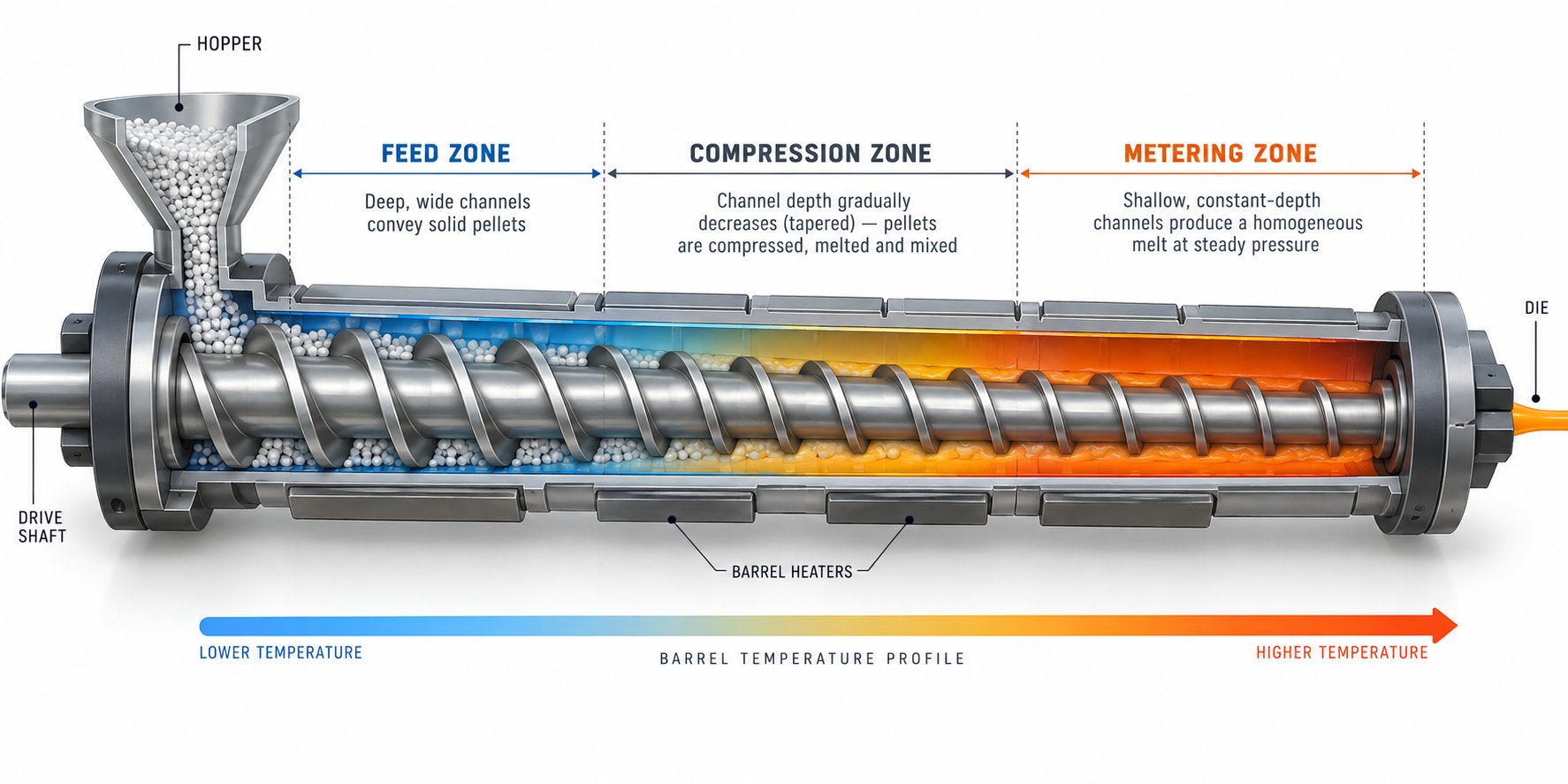
A single screw extruder machine may look like one continuous helix, but the screw is deliberately engineered into three distinct functional zones. Each zone has a different channel depth, a different job, and a different set of design trade-offs. Get the balance between these zones wrong and you will fight quality problems no amount of temperature adjustment can fix. Get it right and the screw practically runs itself.
Feed Zone — Solids Conveying and Why It Sets the Pace
The feed zone is the gatekeeper of the entire process. It begins directly beneath the hopper opening and typically spans four to eight screw turns, featuring the deepest channel on the screw. That generous depth exists for a practical reason: raw pellets are loosely packed and occupy far more volume than the same weight of molten polymer. A deep channel accepts as much bulk material as possible and begins compacting it into a cohesive solid bed that can be pushed forward.
Forward transport here depends almost entirely on friction. The barrel wall must "grip" the pellets more effectively than the screw root does. If the polymer slides too easily against the barrel surface, pellets spin in place and throughput collapses. This is why the feed section is often water-cooled — keeping the barrel surface below the polymer's softening point maintains the frictional bite that initiates conveying.
For high-output applications, especially when processing slippery, high-viscosity polyolefins like HDPE, a grooved feed section can dramatically boost conveying efficiency. Axial or helical grooves machined into the barrel bore mechanically lock pellets against the barrel wall, creating much higher frictional forces than a smooth bore can generate. Case studies comparing groove feed and smooth bore extruders processing HDPE at identical throughputs show that the grooved design achieves lower melt temperatures and reduced power consumption — translating to meaningful energy savings and tighter thermal control. The trade-off is that groove feed systems require a specially designed screw, typically with a shallower feed zone and deeper metering zone, along with intensive cooling of the grooved section itself.
Regardless of bore type, one principle holds: if the feed zone cannot deliver a consistent, well-packed solid bed, every downstream zone suffers. Output surges, inconsistent melting, and pressure fluctuations almost always trace back to solids conveying instability.
Compression Zone — Where Melting and Densification Occur
Imagine the walls slowly closing in on the polymer as it travels downstream. That is essentially what happens in the compression zone, where the channel depth decreases gradually over several screw turns. This tapered geometry serves two critical purposes at once.
First, it mechanically compresses the solid bed, squeezing out the air trapped between pellets and forcing it back through the feed throat. Without this air expulsion, bubbles would carry into the melt and show up as voids or surface defects in the finished product. Second, the shrinking channel increases the shear rate between the polymer and both the barrel wall and screw root. That intensified shear generates substantial frictional heat — often the dominant source of melting energy in the screw extrusion process — while barrel heater bands supply supplementary thermal input.
The majority of phase change from solid to melt occurs within this zone. A thin film of molten polymer forms against the hot barrel wall, and the rotating screw continuously scrapes it away, exposing fresh solid material to the heated surface. The rate at which channel depth decreases — expressed as the compression ratio — must be carefully matched to the polymer being processed. Too aggressive a taper melts material before it is fully compacted, risking air entrapment. Too gentle a taper fails to generate enough shear, leaving unmelted particles that pass into the metering section.
Metering Zone — Homogenization and Pressure Generation
By the time polymer reaches the metering zone, it should be fully molten. This final section features a constant, shallow channel depth — typically the shallowest on the entire screw. The uniform geometry serves as a precision volumetric pump, delivering melt at a consistent rate and building the stable pressure needed to push material through the screen pack, adapter, and die.
The shallow channel is not an arbitrary choice. A thin melt layer shears more uniformly, promoting thermal and compositional homogeneity. You will recall from the drag flow discussion that output is proportional to channel depth — a shallow metering zone limits maximum throughput but provides far better control over melt quality. This is the classic engineering trade-off at the heart of every single screw extrusion machine design: depth versus uniformity.
For applications demanding extra melt consistency, mixing elements such as a Maddock section are often incorporated near the end of the metering zone. These devices force the melt through tight clearances, breaking up any remaining thermal or compositional gradients before the polymer exits the screw tip.
Three Zones at a Glance
The table below distills the key differences across all three zones into a quick-reference format. Use it to understand how channel geometry, function, and design priorities shift as material moves from hopper to die.
| Zone | Channel Depth Characteristic | Primary Function | Key Design Consideration |
|---|---|---|---|
| Feed Zone | Deep and constant | Accept pellets from the hopper and convey a compacted solid bed forward | Channel must be deep enough for bulk density of the feedstock; grooved feed sections improve conveying of slippery polyolefins |
| Compression Zone | Gradually decreasing (tapered) | Compress the solid bed, expel trapped air, and generate shear heating to melt the polymer | Compression ratio must match the polymer's bulk-density-to-melt-density change; too steep risks premature melting, too shallow leaves unmelts |
| Metering Zone | Shallow and constant | Homogenize the melt and build stable pressure for consistent die delivery | Depth balances throughput against melt uniformity; mixing elements can be added to improve thermal homogeneity |
Notice how each zone hands off responsibility to the next in a carefully choreographed sequence. The feed zone delivers a solid bed, the compression zone transforms it into melt, and the metering zone refines that melt into a pressurized, uniform stream ready for the die. Disrupting any link in this chain — whether through worn barrel clearances, an incorrect compression ratio, or an inadequate feed rate — cascades downstream as a quality defect.
The compression zone, however, hides the most complex physics of all three. A thin melt film, a shrinking solid bed, and a growing melt pool all coexist within the same screw channel at the same time. Understanding exactly how this melting mechanism works — and why it so often goes wrong — requires a closer look at the model that polymer engineers have relied on for decades.
How Polymers Actually Melt Inside a Single Screw Extruder
If you cut open a running extruder and froze everything in place, you would not see a neat, uniform transition from solid pellets to molten plastic. Instead, you would find something far more interesting — a solid bed and a melt pool sitting side by side in the same screw channel, separated by a razor-thin film of liquid polymer. This is the melting mechanism that every single screw plastic extruder relies on, yet it remains one of the least understood aspects of the process, even among experienced operators.
The Tadmor Melting Model in Plain Language
In the 1960s, Zehev Tadmor developed a mathematical model of melting in single screw extruders that has stood the test of time. Rather than thinking of pellets melting individually from all sides like ice cubes in warm water, imagine something quite different happening inside the screw channel.
As the compacted solid bed travels into the compression zone, the hot barrel wall heats the polymer surface pressed against it. A thin melt film — often less than a millimeter thick — forms at the interface between the solid bed and the barrel. Here is where the screw's rotation becomes critical. The relative motion between barrel and screw continuously drags this thin melt film across the top of the solid bed, sweeping it toward one side of the channel. The screw flight on the "pushing" side acts like a snowplow, collecting the scraped melt into a growing melt pool.
Picture the cross section of the screw channel at any point along the compression zone: on one side, you have the remaining solid bed; on the other, a pool of molten polymer that expands as you move downstream. The solid bed progressively shrinks in width while the melt pool grows. This is not a random process — it is a continuous, predictable mechanism driven by two variables above all others: the available barrel surface area and the speed of the screw.
Why does barrel surface area matter so much? Because roughly 80% of the melting occurs at the barrel-side interface, where the thin melt film forms. The remaining 20% takes place at the other edges of the solid bed — near the screw root and the screw flights. The melting rate is expressed as a melting flux — the mass of polymer melted per unit area of barrel wall per unit time. More barrel area exposed to the solid bed means faster melting. This is why longer screws with higher L/D ratios generally have greater melting capacity: they simply offer more barrel surface for the melting process to work with.
Screw speed, meanwhile, controls the intensity of viscous shear in the melt film. Faster rotation increases the velocity difference between the barrel wall and the screw, generating more frictional heat within the thin film. A common misconception is that barrel heaters supply most of the energy needed to melt the polymer. In reality, 85–90% of the drive power in a plastic single screw extruder goes directly to melting through viscous shear. The barrel heaters contribute almost nothing once the screw begins rotating — in many operations, they spend most of their time in cooling mode, removing excess heat rather than adding it.
There is an important catch, though. Doubling the screw speed does not double the melting capacity. The melting flux increases with screw speed, but only by a factor of roughly 1.4 times when speed doubles. Meanwhile, the solids conveying and metering sections both double their pumping capacity linearly with speed. This mismatch is the root of many production headaches — push the screw too fast and the solid bed gets shoved downstream past the point where it can fully melt before reaching the die.
Why Understanding Melting Matters for Process Control
The Tadmor model is more than an academic exercise. It directly predicts one of the most damaging failure modes in any screw plastic extruder: solid bed breakup.
Under normal conditions, the solid bed remains a coherent, continuously shrinking mass as it travels through the compression zone. The melt pool grows steadily on one side, and by the time the material reaches the metering section, the solid bed has been entirely consumed. However, when screw speed is too high, back pressure too low, or the compression ratio poorly matched to the resin, the narrowing solid bed can fracture into fragments. These broken chunks lose contact with the barrel wall, tumble into the melt pool, and drift downstream without fully melting.
The result? Solid polymer fragments — sometimes visible as white specks, gels, or unmelts — embedded in the final product. In thin-wall pipe, they appear as undispersed regions that compromise structural integrity. In film, they show up as fish-eyes or hard spots. In sheet, they create surface blemishes that make the product unsaleable. Maddock solidification experiments — where the screw is stopped, the polymer is frozen in place, and cross sections are examined — consistently reveal that solid bed breakup becomes more likely as screw speed increases, because the solid bed is forced farther downstream into territory where there is insufficient barrel surface area to complete the melt.
Three process variables give you the most leverage over where and how completely melting occurs:
- Barrel temperature profile — Higher barrel temperatures in the compression zone increase the melting flux by raising the temperature gradient across the melt film. However, pushing temperatures too high risks thermal degradation, especially with heat-sensitive polymers like PVC. The screw root temperature also plays a role: if the screw itself becomes too hot in the feed section, solids conveying efficiency drops and the entire melting profile shifts unpredictably.
- Screw speed — Increasing RPM intensifies shear heating in the melt film, but it also pushes the solid bed farther downstream. At some threshold, the melting capacity of the barrel is exceeded and unmelted fragments begin to discharge. The only short-term fix when this happens is to reduce screw speed until the fragments disappear.
- Screw geometry — The compression ratio, channel depth transition rate, and overall L/D ratio all determine how much barrel surface area the solid bed is exposed to and how aggressively it is compressed. A screw designed for one polymer may produce excellent results on LDPE but cause severe solid bed breakup on HDPE because the melting characteristics and bulk density profiles differ substantially.
The majority of single screw extrusion defects — gels, unmelts, inconsistent dimensions, and discoloration — originate from either incomplete melting or non-uniform melting within the screw channel.
This insight reframes troubleshooting in a powerful way. Instead of chasing symptoms at the die, you can trace most quality problems back to what is happening inside the compression zone — a place you cannot see during operation but can absolutely influence through screw selection, barrel temperature settings, and speed management.
The melting model also reveals why no single screw geometry works perfectly for all polymers. Each resin has a different specific heat, a different viscosity curve, and a different bulk-density-to-melt-density ratio — all of which change the melting flux and the ideal compression profile. This material dependence is precisely why screw design has evolved well beyond the simple three-zone concept, incorporating barrier flights, mixing sections, and vented configurations that address the specific weaknesses the basic melting mechanism exposes.
Screw Geometry Parameters and Specialized Screw Designs
The melting model makes one thing abundantly clear: screw geometry is not a generic specification you can afford to gloss over. Every dimension on the screw — its length relative to diameter, the rate at which the channel shallows, the depth of each flight — directly shapes melting behavior, mixing quality, and output stability. A screw optimized for LDPE blown film can be a disaster on rigid PVC profiles, not because the steel is different, but because the numbers etched into the design do not match the physics of the new resin. Understanding these numbers and what they control is the difference between a process that runs predictably and one that generates chronic defects.
Key Screw Geometry Parameters and Their Effects
Five parameters define the functional character of any extrusion screw. Adjust one and you inevitably shift the balance between throughput, melting capacity, shear intensity, and residence time. The table below summarizes each parameter, its typical range, and its practical impact on performance.
| Parameter | Typical Range | Effect on Extrusion Performance |
|---|---|---|
| L/D Ratio (Length-to-Diameter) | 24:1 to 36:1 (up to 40:1+ for specialty applications) | Higher L/D provides more barrel surface area for melting and longer residence time for thermal homogenization. Screws below 24:1 often struggle with complete melting at high speeds; those above 36:1 increase capital cost and risk excessive residence time, which can degrade heat-sensitive resins. |
| Compression Ratio | 2:1 to 4:1 (polymer-dependent) | Defines how aggressively the channel volume decreases from feed to metering. Must match the bulk-density-to-melt-density change of the specific resin. Too high a ratio generates excessive shear and premature melting; too low leaves unmelted particles in the metering zone. |
| Flight Depth (Channel Depth) | Varies with diameter and zone; feed-section depth is typically 1.5 to 3 times metering depth | Deeper feed channels accept more bulk material per revolution, boosting throughput potential. Shallower metering channels improve shear uniformity and melt homogeneity but limit maximum output. |
| Pitch (Screw Lead) | Usually equal to screw diameter (1D pitch); also called "square pitch" | A standard square pitch balances forward conveying rate against residence time. Increasing pitch accelerates conveying but reduces the number of turns within a given barrel length, decreasing melting surface exposure. |
| Helix Angle | ~17.66 degrees (for square-pitch screws) | Governs the vector of drag flow along the channel. Deviations from the standard angle alter the balance between forward flow velocity and cross-channel circulation, affecting both output rate and mixing intensity. |
A few of these deserve extra attention. The L/D ratio, for instance, has crept steadily upward over the decades. Where 20:1 or 25:1 was once standard for processing polyolefins and PVC, modern single screw extruder manufacturers commonly offer 30:1 to 36:1 as default specifications. The reason ties directly back to the melting model: a longer screw exposes the solid bed to more barrel surface, improving melting completion at higher screw speeds. As industry references note, increasing L/D extends residence time and improves plasticizing uniformity — but it also makes screw manufacturing more difficult, raises cost, and increases the risk of screw deflection that narrows barrel clearances.
The compression ratio is equally critical and far more polymer-specific. Semi-crystalline resins like HDPE undergo a dramatic density change when they melt (bulk pellet density around 0.55 g/cm3 versus melt density near 0.78 g/cm3), demanding compression ratios of 3:1 to 4:1 or higher. Amorphous resins like polystyrene, which soften gradually without a sharp density transition, perform better with lower ratios around 2:1 to 2.5:1. PVC — rigid granule versus powder — spans a particularly wide range, from 2:1 in granule form up to 5:1 for powder feedstocks, reflecting the enormous variation in starting bulk density. Choosing the wrong compression ratio is one of the most common and costly specification errors in screw extrusion, because the resulting melting problems are built into the hardware and cannot be corrected with process adjustments alone.
Barrier Screws, Mixing Sections, and Vented Designs
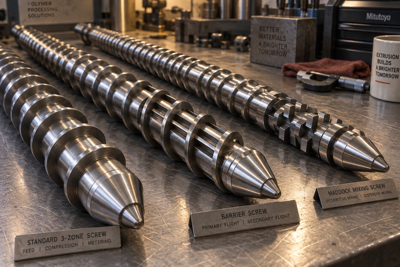
The conventional three-zone screw works reliably across a broad range of applications, but it has an inherent vulnerability that the Tadmor model exposes: the solid bed and melt pool share the same channel with nothing physically preventing solid fragments from breaking loose and drifting into the melt. Specialized screw designs address this weakness head-on.
Barrier Screws — Containing the Solid Bed
Barrier screws introduce a secondary flight — the barrier flight — that physically separates the solids channel from the melt channel. The barrier flight has a slightly smaller diameter than the main flight, creating a controlled clearance between its crest and the barrel wall. Molten polymer can flow over this barrier into the melt channel, but solid fragments cannot pass. The result is a dramatically more stable melting process: the solid bed remains intact and in contact with the barrel wall until it is fully consumed, virtually eliminating solid bed breakup.
The concept was first patented by Dr. C.E. Maillefer in Switzerland in 1959. In the Maillefer design, the solids channel narrows progressively as material melts, while the melt channel widens to accommodate the growing volume of molten polymer. Robert Barr later developed an alternative approach — the alternating-depth barrier screw — where the primary and secondary channels alternate in depth while maintaining a constant screw lead. Robert Dray patented yet another variant that increased melting area by using a longer lead and keeping the primary channel at a constant width. Each design takes a different geometric approach to the same fundamental goal: forcing molten polymer across the barrier flight while keeping unmelted solids physically confined.
Barrier screws proved transformative for high-output applications like blown film, where consistent low melt temperatures and high throughput are both non-negotiable. By the early 1980s, they had become standard in blown film and injection molding plasticating screws, and variations remain widely used across the industry.
Mixing Sections — Breaking the "Single Screws Can't Mix" Myth
A persistent misconception holds that single screw extruders cannot achieve adequate mixing, and that a twin screw compounding extruder is always needed when mixing matters. In reality, purpose-built mixing elements added to the metering section of a single screw can deliver excellent results for many applications. The key distinction is between two types of mixing:
- Dispersive mixing — breaks down solid agglomerates, unmixed gels, or incompatible polymer domains by forcing material through narrow gaps that impose high shear stress. The Maddock mixer (also known as the LeRoy or UCC mixer) is the most widely used dispersive element on single screws. It features pairs of axial flutes — an in-flow channel and an out-flow channel — separated by a mixing flight that is undercut from the main flight. All polymer must flow over this mixing flight, which traps solid polymer fragments and disperses them into the melt matrix. When designed properly, the shear stress generated as resin passes over the mixing flight can reach 200 to 350 kPa — sufficient to disentangle even the stubborn PE gels that cause fish-eyes in film products.
- Distributive mixing — splits, reorients, and recombines melt streams to improve spatial uniformity of temperature, color, and additives without necessarily imposing high shear stress. Pineapple mixers, pin mixing sections, and cavity transfer mixers all accomplish this by repeatedly dividing and recombining flow paths. These elements excel at blending colorant concentrates or homogenizing thermal gradients in the melt stream.
Many modern screw designs combine both types. A common high-performance configuration pairs a barrier melting section with a Maddock dispersive mixer positioned about two diameters from the screw tip. The barrier section prevents solid bed breakup during melting, and the Maddock mixer catches any residual solid fragments or gels that made it through. Poorly designed Maddock mixers, however, can do more harm than good — flutes cut too deep create stagnant regions where resin degrades, eventually contaminating the product with brown specks or black specs. The optimal flute cross section is a semicircle, with depth equal to half the flute width, ensuring smooth flow and minimal dead zones.
Vented (Devolatilizing) Screw Designs
Some processing challenges cannot be solved by melting and mixing alone. When the feedstock carries moisture, trapped air, residual monomers, or volatile contaminants — common scenarios when processing recycled plastics, hygroscopic engineering resins like PET and nylon, or polymers with residual solvent — the screw must provide a way to remove those volatiles before the die.
Vented screw designs accomplish this with a two-stage architecture. The first stage functions much like a conventional screw: it conveys, compresses, melts, and meters the polymer. At the end of this first stage, the channel depth suddenly increases in a decompression zone, dropping melt pressure to near atmospheric levels. A vent port machined into the barrel at this location allows moisture and volatiles to escape as steam or gas. The second stage then re-compresses and meters the devolatilized melt to build die pressure.
The critical design constraint is ensuring the second stage pumps at a slightly higher rate than the first stage delivers. If the vent zone floods — melt pressure rises above atmospheric at the vent port — polymer oozes out of the vent, creating a mess and defeating the entire purpose of the design. Vented screws typically require L/D ratios of 30:1 or greater to accommodate both stages within a single barrel, and they often need starve feeding or a gear pump at the discharge to maintain the delicate pressure balance.
For processors running recycled feedstocks with inconsistent moisture levels, vented barrel designs offer a practical alternative to pre-drying — eliminating dryer capital cost, floor space, and energy consumption. The trade-off is greater mechanical complexity and a narrower operating window that demands careful attention to feed rate and vent zone conditions.
Every specialized design discussed here — barrier flights, dispersive mixers, distributive mixers, and vented configurations — addresses a specific limitation of the basic three-zone screw. Yet none of them changes the fundamental reality that a single screw operates as a drag-flow pump inside a fixed barrel. That inherent architecture defines where the technology excels and where twin screw systems offer genuine advantages — a comparison that deserves more than a superficial treatment.
Single Screw vs Twin Screw Extrusion Compared
A drag-flow pump with a single rotating helix and a pair of intermeshing screws inside a figure-eight barrel are fundamentally different machines — yet the internet is full of oversimplified comparisons that crown one the winner and dismiss the other. The truth is more nuanced. Each architecture solves a different set of problems, and choosing between them comes down to what your material, your product, and your operation actually demand.
When to Choose Single Screw Over Twin Screw Extrusion
Single screw extruders thrive in steady-state processing of pre-compounded materials. When the resin arrives as uniform pellets, already formulated with all necessary additives, the extruder's job is straightforward: melt it, homogenize it, pressurize it, and deliver it to the die at a stable rate. Pipe, blown film, cast sheet, profiles, wire coating — these applications prize output consistency and low operating cost far more than internal mixing intensity. A single screw handles all of them with a simpler mechanical design, fewer wear parts, and lower operator skill requirements.
A twin screw extruder, by contrast, earns its place when the extruder itself must do the compounding. Processing powder feedstocks like rigid PVC dry blend, dispersing high filler loadings, incorporating reactive additives, or devolatilizing contaminated post-consumer recycled streams — these tasks require the intensive mixing, self-wiping action, and modular screw configurations that intermeshing twin screws provide. The capability is real, but so is the price tag: twin screw systems typically cost two to three times more than comparable single screw machines, driven by complex high-torque gearboxes, segmented screw elements manufactured from premium alloy steels, and more sophisticated control systems.
Head-to-Head Technical Comparison
Broad generalizations only go so far. The table below breaks the comparison into nine specific criteria so you can evaluate each factor against your actual process requirements.
| Criteria | Single Screw Extruder | Twin Screw Extruder | Practical Notes |
|---|---|---|---|
| Mixing Capability | Low to moderate; improved with barrier screws and Maddock or pin-mixing sections | Moderate to high; modular screw elements allow precise tuning of dispersive and distributive mixing | For pre-compounded pellets, single screw mixing is usually sufficient. Twin screw is preferred when the extruder must compound the formulation. |
| Capital Cost | Lower — simpler gearbox, one-piece screw, straightforward barrel | Higher — high-torque distribution gearbox, segmented screws, figure-eight barrel bore | Twin screw machines can run 2-3x the cost of a single screw extruder at the same diameter class. |
| Throughput Capacity | High for a given diameter; drag-flow pumping scales well with screw speed | Moderate to high; positive-displacement conveying in co-rotating designs is less diameter-dependent | For simple remelting applications, single screw often achieves higher kg/hr per dollar invested. |
| Maintenance Complexity | Low — fewer parts, longer intervals between screw/barrel replacements | Higher — segmented screws require periodic inspection; intermeshing clearances are tight and sensitive to wear | Single screw is more forgiving of hard contaminants; twin screw intermeshing gaps can jam on metal particles. |
| Material Versatility | Best with clean, consistent pellets or granules | Handles powders, dry blends, variable regrind, and heavily filled compounds | Material form — pellet vs. powder — is often the single most decisive factor. |
| Shear Rate Control | Limited; shear is largely determined by fixed screw geometry and RPM | Highly adjustable; screw element sequence can be reconfigured to target specific shear profiles | Critical for shear-sensitive resins or processes requiring precise energy input. |
| Residence Time Distribution | Broader and less uniform; channel flow is partially plug-like but influenced by pressure flow | Narrower and more uniform in co-rotating designs, thanks to positive conveying and self-wiping action | Narrow residence time distribution reduces degradation risk for heat-sensitive polymers. |
| Energy Efficiency | Generally higher for simple melting tasks; lower frictional losses with a simpler drive train | Can be more efficient on a per-unit-of-qualified-product basis when processing complex feedstocks that would otherwise require multiple passes on a single screw | Compare specific energy (kWh/kg) for your polymer and product, not just motor ratings. |
| Typical Applications | Pipe, film, sheet, profile, wire coating, pelletizing from pre-compounded resin | Compounding, masterbatch, reactive extrusion, PVC dry-blend processing, filled systems, post-consumer recycling with high contamination | Many large-scale recycling lines use a single screw first stage plus twin screw second stage to combine the strengths of both architectures. |
The Overlap Zone — Applications Where Either Can Work
Not every application falls neatly into one column. Several important product categories sit in a gray zone where both architectures can deliver acceptable results, and the final choice hinges on formulation specifics and quality targets.
PVC extrusion is the classic example. Pelletized PVC compounds process comfortably on single screw machines — window profiles, cable ducts, and siding are manufactured this way every day. Rigid PVC dry-blend powder, however, typically steers toward counter-rotating twin-screw extruders because the powder requires more intensive gelation and mixing than a conventional single screw can reliably provide.
Recycling lines present a similar split. Clean, sorted post-industrial scrap — edge trim from film lines, start-up purge, or runners from injection molding — feeds well on single screw systems with grooved barrels and vented designs. Heavily contaminated or mixed post-consumer streams, on the other hand, benefit from the superior degassing, self-cleaning, and mixing capabilities of twin screw extrusion. Many modern recycling facilities bridge the gap by pairing a large single screw extruder for initial melting and coarse filtration with a co-rotating twin-screw extruder downstream for deep degassing and additive incorporation.
Filled polymers occupy the same gray zone. Moderate filler loadings — say 20-30% calcium carbonate in PP — can be dispersed adequately on a well-designed single screw with appropriate mixing sections. Push the loading above 40-50%, add glass fiber, or introduce nano-fillers, and the distributive and dispersive demands usually exceed what a single screw can deliver efficiently.
The takeaway? Avoid defaulting to the assumption that a twin-screw extruder is universally superior. It is a more capable mixer, but it is also a more expensive, more complex, and more maintenance-intensive machine. When the process does not require that extra capability, the simplicity and cost-effectiveness of single screw extrusion deliver better overall value. The right extruder is the one whose architecture matches the actual processing challenge — not the one with the longer spec sheet.
This material-dependent logic extends well beyond the single-vs-twin decision. Even within the single screw world, different polymers demand dramatically different screw geometries, temperature profiles, and processing strategies. A screw that runs HDPE beautifully can wreak havoc on PVC — and understanding why requires a closer look at how individual resin families behave inside the barrel.
Material-Specific Screw Design and Processing Considerations
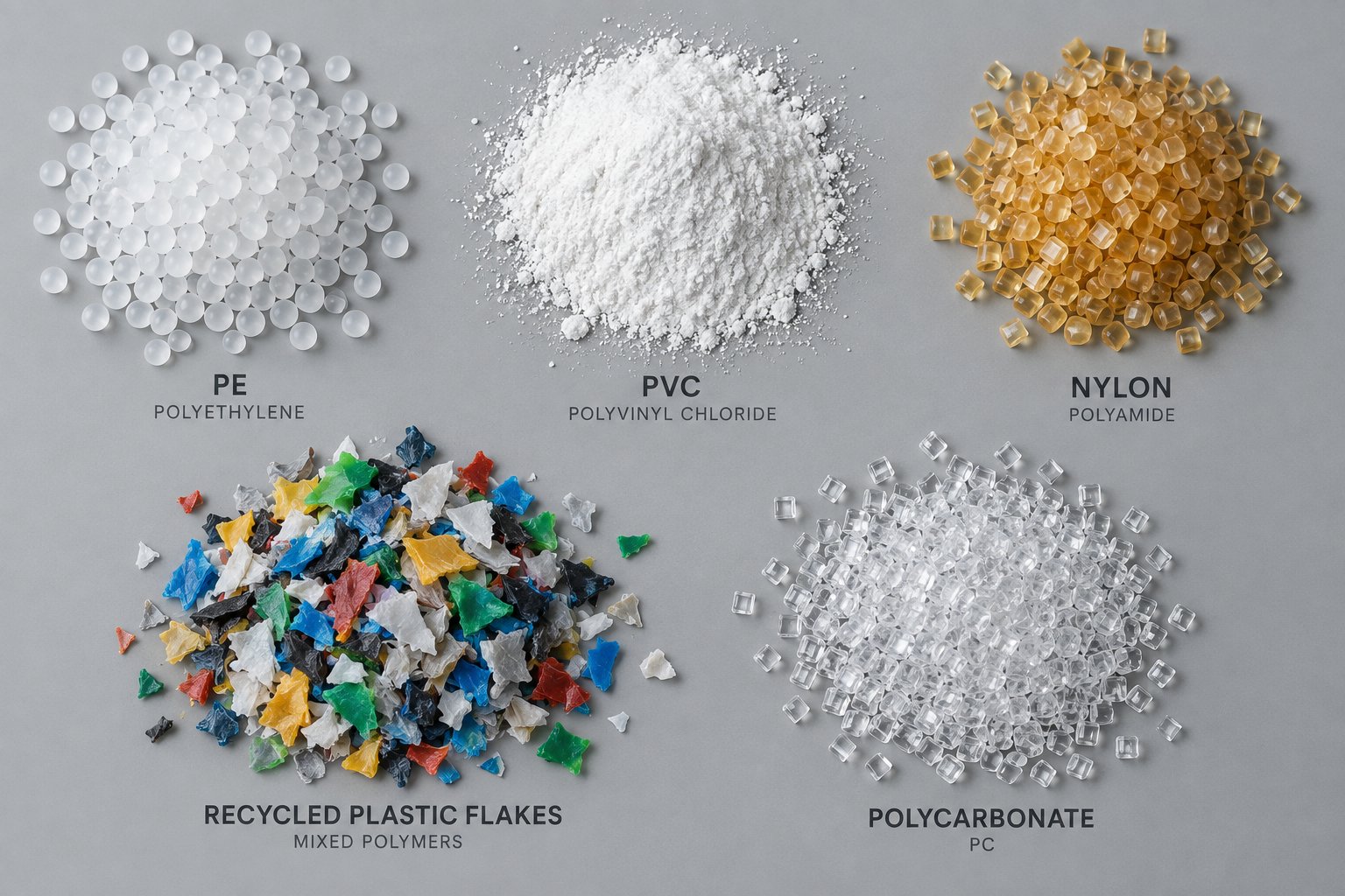
A screw is not a universal tool. The geometry that melts HDPE at 500 kg/hr with beautiful melt consistency can produce degraded, discolored output when you swap in rigid PVC — even at identical barrel temperatures and screw speeds. Why? Because every polymer family brings a unique combination of melting behavior, thermal sensitivity, bulk density, and viscosity characteristics that the screw must accommodate. Matching the screw to the material is arguably the single most impactful decision in the entire extrusion process, yet it is the one most frequently overlooked by processors who treat screw selection as a one-size-fits-all exercise.
Polyolefins, PVC, and Styrenics — Tailoring the Screw to the Resin
The split between semi-crystalline and amorphous polymers creates two fundamentally different melting profiles that demand different screw architectures.
Semi-crystalline polymers like polyethylene (PE) and polypropylene (PP) undergo a sharp phase transition at a well-defined melting point. Below that temperature, the material remains a rigid solid; above it, it transitions rapidly to a low-viscosity melt. This abrupt density change — bulk pellet density around 0.55 g/cm3 jumping to a melt density near 0.78 g/cm3 for HDPE — requires high compression ratios, typically 3:1 to 4:1, to account for the dramatic volume reduction. Screws designed for polyolefins also benefit from grooved feed sections, which mechanically lock the slippery pellets against the barrel wall and prevent them from spinning in place. Research at the University of Stuttgart has demonstrated that grooved feed zones are particularly critical for polyolefins, where the reduction in bulk density associated with regrind can otherwise slash specific throughput and narrow the usable process window.
Amorphous polymers like polystyrene (PS) and ABS behave very differently. They soften gradually across a broad temperature range rather than melting at a distinct point. The bulk-density-to-melt-density change is far less dramatic, so compression ratios of 2:1 to 2.5:1 are sufficient. Excessive compression on amorphous resins generates unnecessary shear heating, which can degrade the rubber phase in ABS or cause yellowing in clear PS. Screw designs for styrenics generally use shallower feed sections and gentler compression tapers, paired with distributive mixing elements that homogenize temperature without imposing punishing shear stress.
PVC occupies its own category — and for good reason. Whether processed from pellets or powder dry blend, PVC has the narrowest processing window of any commodity resin. The gap between adequate gelation temperature and the onset of thermal degradation is often less than 20 degrees Celsius. Push too far and the polymer releases hydrochloric acid gas, which corrodes barrel and screw surfaces and contaminates the product. The compression ratio for PVC varies widely depending on feedstock form: pelletized compounds typically need 2:1 to 2.5:1, while powder dry blends — with their very low initial bulk density — may require ratios up to 5:1. Temperature control must be exceptionally precise, and the screw design should minimize localized shear peaks that could trigger degradation in stagnant pockets. Many PVC processors rely on conical counter-rotating twin screws for this reason, but well-designed single screw systems handle pelletized PVC compounds reliably in pipe, profile, and sheet applications every day.
Engineering Plastics and Recycled Feedstocks
Step beyond commodity resins and the processing challenges intensify. Engineering thermoplastics and recycled feedstocks each introduce complications that a standard general-purpose screw simply cannot handle.
Hygroscopic materials like PET and nylon (PA6 and PA66) absorb atmospheric moisture that causes hydrolysis during melt processing. Even 0.1% residual moisture in nylon can reduce molecular weight enough to make the final product brittle. Pre-drying before extrusion is standard practice, but it adds capital cost, floor space, and energy consumption. Vented screw designs offer a compelling alternative — or supplement — by removing moisture as steam through barrel vent ports during processing. The decompression zone and second-stage metering must be carefully designed to prevent vent flooding, particularly at higher throughputs. Barrel metallurgy also matters: nylon releases acidic byproducts at processing temperatures of 260-290 degrees Celsius, so nitrided steel or bimetallic barrel liners are essential to prevent corrosion and product contamination.
Polycarbonate (PC) presents a different hurdle altogether. Its exceptionally high melt viscosity demands significant torque from the drive system and high barrel temperatures to achieve adequate flow. The screw should employ a gradual compression ratio to build pressure without overloading the motor. PC is also extremely sensitive to moisture — even trace amounts cause splay marks on molded or extruded surfaces — so either thorough pre-drying or effective vacuum venting is non-negotiable.
Recycled feedstocks may be the most demanding category of all. Unlike virgin pellets, which arrive in consistent shapes and sizes, regrind and post-consumer recyclate vary in bulk density, particle geometry, contamination level, and moisture content — sometimes from bag to bag. These inconsistencies wreak havoc on solids conveying. Irregularly shaped regrind particles pack less efficiently than cylindrical virgin pellets, reducing bulk density and lowering specific throughput. Experimental work on PE-HD and PP regrind showed that switching from virgin pellets to regrind reduced specific throughput by up to 37% in a standard grooved feed extruder — a massive productivity hit that also raised melt temperatures and shrank the usable operating window. Novel feed zone geometries with enlarged filling diameters and grooved compression sections have been shown to fully align regrind throughput with virgin material performance, essentially restoring the lost process window.
Beyond feed zone challenges, recycled plastics often carry moisture, residual printing inks, adhesives, and mixed polymer contaminants. Vented barrel designs with vacuum extraction handle volatile contaminants effectively, while screen changers downstream filter out solid particulates. The combination of grooved feed zones, vented barrels, and robust filtration systems transforms a standard extruder into a recycling-capable line without requiring the higher capital investment of a double screw extruder machine.
Polymer-by-Polymer Quick Reference
The following list organizes common polymers into processing categories, each with key screw design and processing notes. Use it as a starting point when specifying or evaluating a screw for a new material.
- Semi-Crystalline Polyolefins (HDPE, LDPE, LLDPE, PP) — Sharp melting point; high compression ratios (3:1 to 4:1); grooved feed sections strongly recommended for PE; barrier screw designs improve melting consistency at high speeds; most melting energy comes from viscous shear rather than barrel heaters.
- Amorphous Commodity Resins (PS, HIPS, ABS, SAN) — Gradual softening; lower compression ratios (2:1 to 2.5:1); moderate barrel temperatures (200-250 degrees Celsius); ABS is shear-sensitive — avoid aggressive mixing sections that could degrade the rubber phase; distributive mixing preferred over dispersive for color blending.
- PVC (Rigid and Flexible) — Extremely narrow processing window; compression ratio varies from 2:1 (pellets) to 5:1 (powder); precise temperature control essential to prevent HCl release and degradation; corrosion-resistant barrel liners recommended; low screw speeds reduce shear heating risk.
- Engineering Plastics (PA6, PA66, PET, PBT, PC) — Hygroscopic; require pre-drying or vented screw designs; high processing temperatures (250-320 degrees Celsius); corrosion-resistant barrel materials needed for nylon; PC demands high torque and gradual compression; PET requires strict residence time control to maintain intrinsic viscosity.
- Recycled and Regrind Feedstocks — Inconsistent bulk density and particle shape; grooved feed zones with enlarged filling diameters help normalize throughput; vented barrels remove moisture and volatiles without pre-drying; screen changers essential for particulate filtration; a parallel twin screw extruder may be warranted for heavily contaminated post-consumer streams requiring deep degassing and reactive stabilization.
Every entry on this list reinforces the same core principle: the screw must be designed around the material, not the other way around. Selecting a general-purpose screw and hoping it handles everything from PP homopolymer to glass-filled nylon is a recipe for chronic quality issues, excessive energy consumption, and premature wear. The payoff for getting this match right — in throughput, product consistency, and screw life — far outweighs the cost of specifying the correct geometry upfront.
Material-screw mismatches, however, are not the only source of trouble. Even a perfectly matched screw and resin can produce defective output if process parameters drift or interact in unexpected ways. Knowing how to identify common extrusion defects, trace them back to their root causes, and apply systematic corrective actions separates processors who react from those who resolve.
Troubleshooting Common Single Screw Extrusion Defects
A perfectly specified screw matched to the right resin can still produce scrap if process parameters slip out of alignment. The frustrating part? Extrusion defects rarely announce their cause. A rough surface could stem from a temperature setting, a worn barrel, or a resin batch variation — and the same symptom can have entirely different root causes depending on the polymer and product. What separates experienced operators from everyone else is a structured approach to diagnosis rather than random knob-turning.
Identifying Common Extrusion Defects and Their Root Causes
When a defect appears at the die, your first instinct might be to adjust whatever is closest — die temperature, haul-off speed, or screw RPM. Resist that urge. Instead, classify the defect, identify the most probable root causes, and then apply targeted corrections. The table below covers the seven most frequent quality problems encountered on screw extruders and maps each one to actionable fixes.
| Defect | Visual Symptom | Likely Root Causes | Recommended Corrective Actions |
|---|---|---|---|
| Surging (Output Fluctuation) | Periodic variation in product dimensions, pulsating extrudate, cycling die pressure | Inconsistent solids conveying; solid bed breakup in the compression zone; worn screw or barrel increasing clearance; inconsistent feed rate or bridging in the hopper | Check feed throat for blockages; verify barrel and screw dimensions for wear; reduce screw speed to stabilize the solid bed; ensure consistent pellet size and flow from hopper |
| Melt Fracture | Spiral patterns, gross distortion, or wavy ripples on the extrudate surface | Melt velocity exceeding the polymer's critical shear rate at the die land; melt temperature too low, raising viscosity and wall stress | Raise melt temperature to reduce viscosity; widen the die gap; reduce throughput; consider adding a fluoropolymer processing aid (PPA) as a last resort |
| Shark Skin | Fine, regularly spaced ridges or roughness running along the extrusion direction — distinct from the gross distortion of melt fracture | Excessive surface stress at the die exit as the extrudate relaxes; die lip temperature too low | Raise die lip temperature; activate die lip heaters if equipped; increase die gap slightly; reduce extrusion speed |
| Die Drool | Buildup of degraded or low-molecular-weight material at the die exit, periodically breaking free and attaching to the product surface | Volatile additives or low-MW polymer fractions migrating to the die exit and accumulating; die temperature too high or too low relative to the resin's volatility | Optimize die temperature to minimize volatile migration; clean die lips regularly; review additive package for thermal stability; consider PPA to reduce surface accumulation |
| Gels and Unmelts | Small, clear or opaque specks visible in film or thin-wall products; hard spots or fish-eyes that reflect light differently from the surrounding material | Solid bed breakup allowing unmelted fragments into the metering zone; high-molecular-weight tails in the resin (P-gels); degraded polymer from stagnant zones in the screw or die (E-gels); contamination in the feedstock | Reduce screw speed to allow complete melting; increase barrel temperatures in the compression zone; inspect the screw for dead spots and worn flights; verify incoming resin quality; add a dispersive mixing section (e.g., Maddock mixer); use finer screen packs or depth filtration media |
| Discoloration or Degradation | Yellowing, browning, dark streaks, or black specks in the extrudate | Excessive melt temperature causing thermal decomposition; prolonged residence time in stagnant zones; contaminated resin or incompatible additive carrier | Lower barrel temperatures to recommended levels; reduce screw speed to decrease shear heating; purge and inspect screw and die for stagnant regions; verify additive thermal stability |
| Poor Dimensional Consistency | Wall thickness variation, ovality in pipe, width or gauge drift in film or sheet | Uneven die temperatures; melt pressure fluctuations from feed instability; inconsistent cooling; die misalignment relative to the screw axis | Check and re-gap the die; verify thermocouple accuracy across all barrel zones; ensure cooling system symmetry; center the die with respect to the downstream calibration tooling; stabilize feed rate |
You will notice a pattern running through almost every row of that table. Gels and unmelts stem from incomplete melting. Discoloration stems from excessive heat or residence time. Surging traces back to feed instability that disrupts the melting process. Even melt fracture and shark skin — which appear to be die-related — are strongly influenced by how completely and uniformly the polymer was melted upstream.
Process Parameter Adjustments to Resolve Quality Issues
Here is where troubleshooting gets tricky: screw speed, barrel temperature profile, back pressure, and feed rate are not independent dials you can twist in isolation. They form an interconnected system where adjusting one variable inevitably shifts the others.
Imagine you increase screw speed to boost throughput. That raises shear heating in the melt film, which can improve melting — but it also pushes the solid bed farther downstream, potentially beyond the barrel's melting capacity. The faster-arriving melt simultaneously increases die pressure, which increases the pressure flow component working against output. You wanted more throughput but may end up with unmelts at the die and only a marginal gain in output.
Raising barrel temperatures seems like a straightforward way to improve melting, and it often works — up to a point. For heat-sensitive materials like PVC or certain polyester formulations, even a 10-degree overshoot can initiate degradation, producing the very discoloration or dark specks you were trying to avoid. The barrel temperature profile also affects viscosity: hotter melt in the metering zone flows more easily, which reduces back pressure and can actually decrease mixing quality and melt homogeneity.
Back pressure — generated by the screen pack, breaker plate, and die restriction — is often treated as a fixed condition, but it is one of the most powerful levers for improving melt quality. Increasing back pressure forces the melt through tighter passages, extending residence time in the metering zone and improving dispersive action across screen packs. However, excessive back pressure reduces net output (remember the drag flow minus pressure flow relationship) and raises melt temperature through additional viscous dissipation.
The most effective troubleshooting approach is systematic and sequential:
- Isolate one variable at a time. Change the barrel temperature in the compression zone by 5-10 degrees, then run enough product to observe the effect before touching anything else.
- Track melt temperature at the die, not just barrel setpoints. The actual melt temperature reflects the combined effect of barrel heating and shear input — it is the single most informative measurement on the entire machine.
- Document every change and its result. Extrusion processes have memory. A change you made twenty minutes ago may not show its full effect until the new thermal equilibrium propagates through the barrel.
- Check the hardware before blaming the process. Worn flights, a barrel bore that has enlarged beyond tolerance, or a damaged thermocouple can mimic process-related defects. As extrusion engineering experts emphasize, screw wear changes how material flows through the extruder, causing output problems that no temperature adjustment can fix.
Most single screw extrusion defects originate from one of two failure modes: incomplete melting that sends solid fragments to the die, or excessive thermal exposure that degrades the polymer before it gets there.
This dual-failure-mode framework simplifies what can otherwise feel like an overwhelming number of variables. Every corrective action you take should move the process away from one of these two extremes — toward complete, uniform melting at the lowest temperature that achieves it. That balance point, however, does not find itself. It requires deliberate optimization of barrel temperature profiles, screw speed, and energy input — along with attention to barrel and screw condition that is easy to neglect until productivity has already suffered.
Process Optimization and Energy Efficiency in Single Screw Extrusion
Finding that sweet spot between complete melting and minimal thermal exposure is not a one-time event — it is an ongoing optimization exercise. The troubleshooting framework from the previous section tells you what went wrong and where to look. This section tells you how to dial the process in proactively, squeezing more throughput from every kilowatt and every degree of barrel heat before defects ever appear.
Optimizing Barrel Temperature Profiles Zone by Zone
Every barrel zone has a job, and the temperature you assign it should reflect that job — not a blanket setpoint copied from a material data sheet. Three basic temperature profile strategies cover the vast majority of single screw extrusion applications:
- Ascending profile — Temperatures increase steadily from the feed throat to the die. This is the safest starting point for most semi-crystalline resins like PE and PP, where progressive heat input supports the natural melting sequence without shocking the solid bed.
- Humped profile — Barrel temperatures in the compression zone are set higher than both the feed and metering zones. Research by Mark Spalding at Dow demonstrates why this works: the melting flux at the barrel wall increases with temperature. For LDPE, raising the barrel temperature from 190 degrees Celsius to 250 degrees Celsius boosts the melting flux by roughly 20%. Once the polymer is fully molten, lower metering zone temperatures help bring the discharge temperature back down. This strategy is especially effective for eliminating solid polymer fragments without overheating the melt.
- Flat or reverse profile — Used primarily for shear-sensitive materials like rigid PVC, where the barrel heaters are set low and the machine relies almost entirely on viscous shear to generate melt energy. In some cases, barrel cooling is active across most zones, removing excess shear heat rather than adding thermal input.
Choosing between these profiles matters, but so does knowing where your barrel zones physically align with the screw's functional sections. A "compression zone" temperature setpoint does nothing useful if that heater band actually sits over the metering flights. Mapping barrel zone locations to the solids conveying, melting, and metering sections of the screw is the essential first step — and one that surprisingly few processors bother to verify after a screw change.
Feed zone barrel temperatures deserve particular attention. The goal here is not to melt the polymer but to maximize the frictional grip between pellets and barrel wall. For amorphous resins like HIPS, experimental data shows there is an optimal barrel wall temperature — around 165 degrees Celsius for HIPS — where the frictional shear stress peaks. Setting the feed zone too hot softens the pellets prematurely, causing them to stick to the screw root rather than conveying forward. Too cold, and the friction coefficient drops, starving the downstream zones.
Back pressure from screen packs and die geometry also shapes the optimization picture. A finer mesh screen pack increases back pressure, which improves melt filtration and homogeneity but simultaneously increases the pressure flow component that opposes output. You will recall that net extruder output equals drag flow minus pressure flow — so tightening the screen pack always costs some throughput. The practical trade-off is product quality versus production rate, and the optimum balance depends on the defect tolerance of your specific product.
One relationship trips up operators more than any other: screw speed versus output. Doubling the RPM does not double the throughput. Drag flow scales linearly with screw speed, but the higher die pressure generated by faster pumping simultaneously increases the opposing pressure flow. At the same time, the melting capacity of the barrel does not keep pace — melting flux scales roughly with the square root of screw speed, not linearly. Push too fast and you exceed the barrel's ability to fully melt the solid bed, sending unmelted fragments straight to the die. This mismatch explains why experienced processors often achieve the highest quality output at moderate screw speeds with optimized temperature profiles rather than by running flat out.
Energy Efficiency and Throughput Estimation
Energy cost per kilogram of product — specific energy consumption, measured in Wh/kg or kWh/kg — is the metric that ties process optimization directly to profitability. It includes both mechanical energy from the drive motor and thermal energy from the barrel heaters. The lower your specific energy, the less you spend on electricity for every meter of pipe, roll of film, or bag of pellets you produce.
How that energy enters the polymer matters as much as the total amount. In an efficient single screw extrusion process, the dominant energy source is viscous shear heating — the mechanical work the rotating screw imparts to the polymer through friction and deformation. Industry experts estimate that barrel heaters contribute relatively little once the screw is rotating at production speeds. In many well-optimized processes, barrel heaters in the metering zone spend more time cooling than heating, pulling excess shear energy out of the melt rather than adding to it. This is sometimes called adiabatic extrusion — a condition where virtually all melting energy comes from the drive motor, and barrel heaters serve only as fine-tuning instruments.
Specific energy values vary significantly by polymer. PVC pipe extrusion, for example, requires approximately 100 Wh/kg at the extruder and an additional 15-25 Wh/kg at the die, with a theoretical minimum around 80 Wh/kg. Polyolefins demand roughly three times more drive energy than PVC due to their higher melting enthalpies and melt viscosities. These numbers provide a benchmark: if your actual specific energy significantly exceeds published targets for your polymer, something in the process — screw design, barrel condition, or operating parameters — is wasting energy.
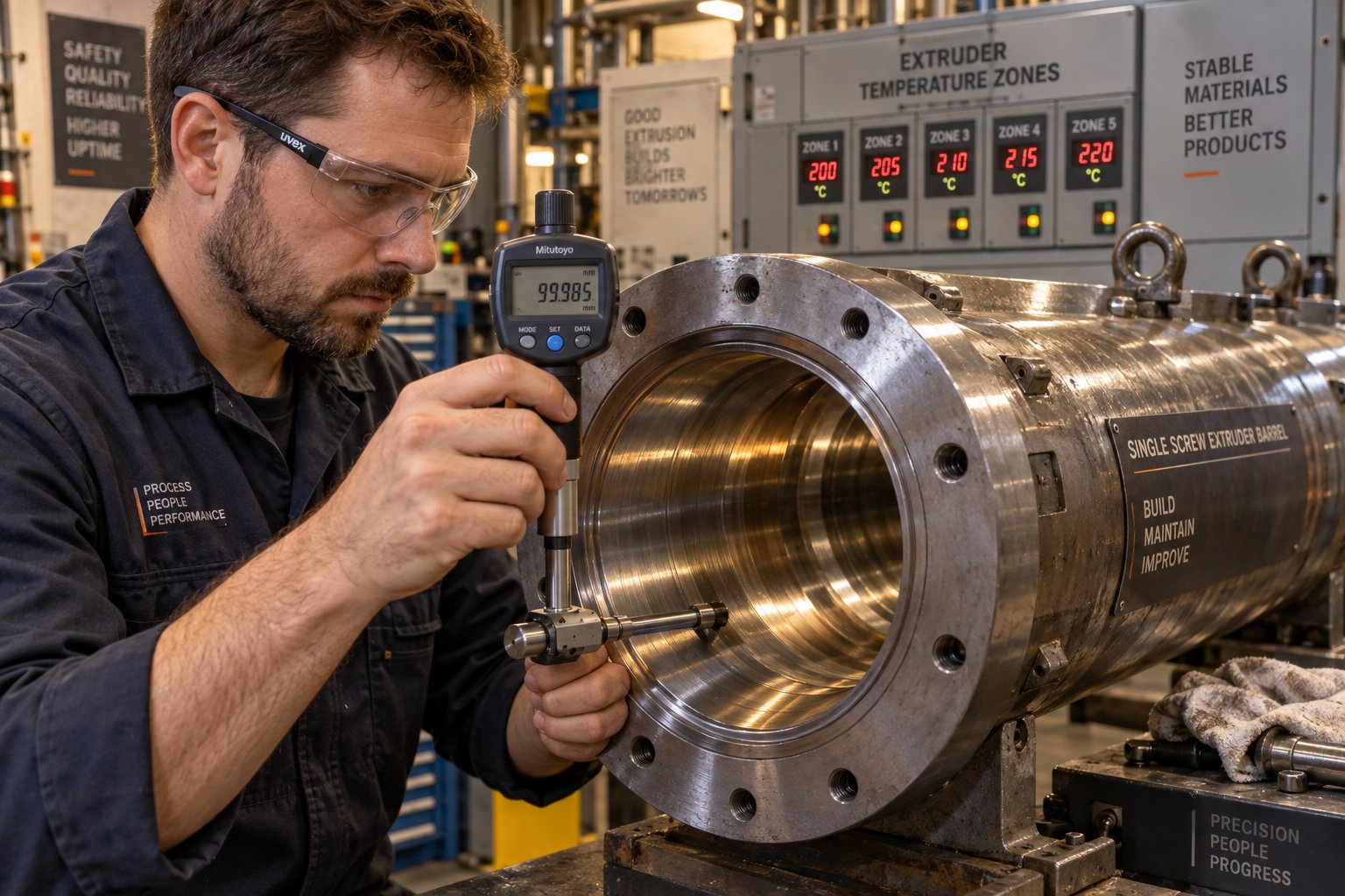
One of the most overlooked sources of energy waste is worn hardware. As the gap between screw flight and barrel bore increases through normal wear, material leaks backward over the flights instead of being pushed forward. Industry case studies show that a 10% decrease in screw outside diameter due to flight wear can reduce output by up to 25%. The machine compensates by running faster, consuming more power, and generating more shear heat — all without producing any additional product. A throughput test comparing actual output at maximum screw speed against the manufacturer's rated capacity is a quick diagnostic: if you find a capacity reduction of 15% or more, the screw and barrel have significant wear that demands attention.
Worn barrels are equally damaging. When the barrel bore enlarges beyond tolerance, the screw-barrel clearance grows and conveying efficiency drops. The extruder must work harder — higher speeds, higher motor current — to deliver the same output. The excess mechanical energy converts to heat, raising melt temperatures and increasing the risk of thermal degradation. Replacing a worn barrel restores the tight clearances that efficient drag-flow pumping depends on. Suppliers like NANHAIYA offer custom and replacement single screw barrels engineered for specific extrusion applications — pipe, film, sheet, pelletizing, and recycling lines — which can restore optimal clearance and improve both throughput and energy efficiency.
Practical Tips for Improving Energy Efficiency
Energy optimization does not require a complete line rebuild. The following measures deliver measurable savings on existing equipment, often with minimal capital investment:
- Optimize screw design for the target polymer. A screw matched to the resin's melting behavior, compression ratio, and viscosity profile extracts maximum throughput per RPM, reducing the speed — and therefore the energy — needed to hit your output target.
- Use insulating barrel covers. Exposed barrel surfaces radiate heat directly into the plant environment. Insulating jackets reduce radiant and convective losses, stabilize zone temperatures, and decrease the energy the heater bands must supply to maintain setpoints.
- Minimize screw speed while maintaining output targets. Lower RPM means less shear heating, lower melt temperatures, and less energy consumed by the drive motor. If the current screw cannot deliver the required rate at moderate speed, the screw geometry — not the speed setting — is the variable that should change.
- Maintain proper barrel-screw clearance. Schedule regular bore measurements and screw flight inspections. Replace worn components before efficiency drops noticeably. Even a small increase in clearance allows backward leakage that robs throughput and wastes motor energy.
- Monitor specific energy continuously. Track kWh per kilogram of output over time. A rising trend — especially without a change in material or product — is an early warning of wear, process drift, or suboptimal operating conditions.
- Review screen pack and die design for unnecessary restriction. Over-filtering or running an undersized die raises back pressure beyond what quality demands, converting the excess into wasted shear heat and reduced output.
Each of these actions returns you to the central principle that has threaded through this entire article: efficient single screw extrusion is a system-level outcome. Screw geometry, barrel condition, temperature profile, and operating speed are not isolated dials — they are an interconnected machine that must be tuned as a whole. The final piece of that system-level thinking is knowing when single screw technology is the right solution in the first place, and how to specify the screw and barrel combination that will deliver the best long-term performance for your specific application.
Choosing the Right Single Screw Extrusion Setup for Your Needs
You have walked through the physics of drag flow and pressure flow, dissected the three functional zones, examined how polymers actually melt inside the barrel, compared single and twin screw architectures, matched screw designs to specific resins, diagnosed common defects, and optimized process parameters for energy efficiency. That is a substantial body of knowledge — but knowledge without a decision framework leads to analysis paralysis. The question most processors ultimately face is deceptively simple: is single screw extrusion right for my application, and if so, how do I specify the screw and barrel combination that will deliver reliable performance for years?
Decision Framework — Is Single Screw Extrusion Right for Your Application
Rather than treating this as an intuitive judgment call, work through the following five-step evaluation. Each step narrows the field and points you toward either a single screw or a twin screw solution — or, in some cases, a hybrid approach that combines elements of both.
- Identify the target polymer and whether it is pre-compounded.
If your feedstock arrives as uniform, pre-compounded pellets — PE, PP, PS, ABS, PET, or pelletized PVC compounds — a single screw extruder is almost always the practical starting point. The machine's primary job is remelting and shaping, not formulating. If the feedstock is powder, dry blend, or a raw recipe requiring ingredient incorporation, the decision shifts toward twin screw extruders that offer the intensive mixing these materials demand. - Define mixing and compounding requirements.
Ask yourself: does the extruder need to blend incompatible additives, disperse high concentrations of mineral fillers, or achieve chemical reactions inside the barrel? If the answer is no — the formulation is already complete — then a single screw with appropriate mixing elements (barrier flights, a Maddock section, or pin mixers) provides sufficient homogenization. If the answer is yes, a co-rotating twin screw or a tandem line combining both architectures deserves serious evaluation. - Estimate required throughput.
Single screw machines scale efficiently across a very wide output range — from laboratory-scale units producing a few kilograms per hour to industrial lines exceeding 2,000 kg/hr. For straightforward remelting applications like pipe, film, and sheet, a single screw typically delivers more kilograms per dollar invested than twin screw alternatives at equivalent diameters. However, if the process requires throughput to be decoupled from screw speed — common in reactive extrusion or highly filled compounds — twin screw extruders offer greater flexibility. - Consider budget constraints for capital and maintenance.
Single screw systems carry lower purchase prices, simpler spare parts inventories, reduced operator training requirements, and less demanding maintenance schedules. If your operation prioritizes low total cost of ownership and values mechanical simplicity, single screw is the natural fit. Twin screw machines justify their higher cost only when the process genuinely requires capabilities that a single screw cannot deliver — intensive mixing, powder handling, or modular screw reconfiguration. - Evaluate whether venting or devolatilization is needed.
Moisture removal, volatile extraction, and degassing can be accomplished on either platform. Vented single screw designs with a decompression zone and barrel vent port handle hygroscopic resins like nylon and PET effectively, and they manage recycled feedstocks with moderate moisture and volatile levels. For deep devolatilization of heavily contaminated post-consumer streams or processes requiring multiple vent stages, twin-screw extruders provide superior vapor extraction efficiency. Many recycling operations split the difference by pairing a single screw first stage for initial melting with a twin screw downstream unit for degassing and additive incorporation.
If steps one through four consistently point toward pre-compounded pellets, moderate mixing, cost-effective throughput, and operational simplicity, a single screw extruder is almost certainly the right architecture. If two or more steps flag intensive mixing, powder feedstocks, or complex devolatilization, evaluate twin screw extruders or hybrid configurations before committing. The most expensive mistake in extrusion equipment procurement is forcing the wrong architecture onto an application it was never designed to serve — whether that means overspending on twin screw capability you do not need, or underspecifying a single screw that cannot handle your material's demands.
Selecting the Right Screw and Barrel for Long-Term Performance
Choosing the correct extruder architecture is only half the equation. The screw and barrel you install inside that machine determine whether the system delivers consistent, defect-free output for years — or becomes a recurring source of quality problems, premature wear, and wasted energy.
Think of it this way: the extruder frame, motor, and gearbox are the platform. The screw and barrel are the engine. You would not drop a generic engine into a vehicle designed for a specific duty and expect optimal performance. The same principle applies here. A screw geometry optimized for your target polymer, your throughput range, and your product type prevents the cascade of issues explored throughout this article — incomplete melting, solid bed breakup, thermal degradation, surging, and excessive energy consumption.
Several factors deserve attention when specifying or replacing screws and barrels:
- Compression ratio matched to resin. Semi-crystalline polyolefins demand 3:1 to 4:1; amorphous resins like PS and ABS perform better at 2:1 to 2.5:1; PVC spans a wide range depending on feedstock form. A mismatch here creates melting problems that no process adjustment can overcome.
- L/D ratio appropriate for the application. Standard applications run well at 24:1 to 30:1. Vented designs, barrier screws with extended melting sections, or processes requiring deep thermal homogenization typically push to 32:1 or 36:1.
- Mixing section selection. Barrier flights prevent solid bed breakup. Maddock mixers catch residual gels and unmelts. Distributive elements homogenize temperature and color. The right combination depends on the defect sensitivity of your final product.
- Barrel metallurgy and bore finish. Standard nitrided steel barrels suit unfilled commodity resins. Glass-filled, mineral-filled, or highly abrasive recycled feedstocks demand bimetallic barrel liners with tungsten carbide or nickel-based alloy inner surfaces to resist accelerated wear. The bore finish quality directly affects conveying efficiency and melt film formation.
- Dimensional tolerances. Screw flight-to-barrel clearance is measured in hundredths of a millimeter. Exceeding the recommended clearance — typically around 0.1 to 0.15 mm per side for standard diameters — allows backward leakage flow that robs throughput, wastes energy, and degrades melt quality.
This is where working with a specialist supplier pays dividends. Manufacturers like NANHAIYA specialize in custom single screw barrels tailored to specific extrusion applications — whether pipe, film, sheet, pelletizing, or recycling. Rather than offering a one-size-fits-all barrel, a specialist supplier engineers the barrel metallurgy, bore finish, and dimensional tolerances to match the demands of the target process. For processors running multiple product lines or different polymer families, that application-specific approach means each barrel is optimized for its duty rather than compromised as a generic solution.
Replacement timing matters just as much as specification quality. As explored in the energy efficiency discussion, worn barrels and screws silently erode throughput and inflate power consumption long before the wear becomes visible in product quality. Establishing a baseline barrel bore measurement at installation — and re-measuring at scheduled intervals — gives you objective data on wear progression rather than relying on guesswork. When measurements indicate the clearance has reached the replacement threshold, sourcing a precision-manufactured replacement barrel from a supplier like NANHAIYA restores the tight tolerances that efficient drag-flow conveying depends on, recovering lost throughput and reducing the specific energy your line consumes per kilogram of output.
The broader point is this: the screw and barrel are not permanent fixtures. They are engineered wear components that define the upper limit of what your extrusion line can achieve. Investing in application-specific designs upfront — and replacing them with equally well-specified components when wear demands it — protects every other investment you have made in the extruder, the die, the downstream equipment, and the operating team that runs them.
Mastering single screw extrusion requires understanding the interaction between screw design, barrel condition, material properties, and process parameters. No single variable operates in isolation — and the processors who treat their extrusion line as an integrated system, from feed throat to finished product, are the ones who consistently achieve defect-free output at the lowest cost per kilogram.
Frequently Asked Questions About Single Screw Extrusion
1. What is the difference between single screw and twin screw extrusion?
Single screw extrusion uses one helical screw rotating inside a cylindrical barrel to melt and shape pre-compounded plastic pellets. It excels in steady-state applications like pipe, film, and sheet production, offering lower capital cost and simpler maintenance. Twin screw extrusion uses two intermeshing screws inside a figure-eight barrel, providing superior mixing, compounding, and devolatilization capabilities. Twin screw systems cost two to three times more and are chosen when the extruder must blend raw ingredients, disperse high filler loadings, or process powder feedstocks. The right choice depends on whether your application prioritizes cost-effective remelting (single screw) or intensive in-barrel compounding (twin screw).
2. What are the three zones of a single screw extruder?
The three functional zones are the feed zone, compression zone, and metering zone. The feed zone has the deepest channel and accepts raw pellets from the hopper, compacting them into a solid bed through frictional conveying against the barrel wall. The compression zone features a gradually decreasing channel depth that squeezes out trapped air and generates shear heating to melt the polymer — this is where the majority of phase change occurs. The metering zone has a shallow, constant-depth channel that acts as a precision pump, homogenizing the melt and building stable pressure for consistent delivery through the die. Each zone hands off to the next in sequence, and disrupting any link cascades downstream as a quality defect.
3. How does a single screw extruder melt plastic?
Melting in a single screw extruder follows the Tadmor contiguous solids melting mechanism. As the compacted solid bed enters the compression zone, the hot barrel wall creates a thin melt film at the polymer-barrel interface. The rotating screw continuously scrapes this film off and sweeps it into a growing melt pool on one side of the screw channel. The solid bed progressively shrinks in width as the melt pool expands. Approximately 85-90% of the melting energy comes from viscous shear heating generated by the screw's rotation, not from barrel heaters. Barrel surface area and screw speed are the two primary variables controlling the melting rate, which is why longer L/D ratio screws generally offer greater melting capacity.
4. What causes surging in a single screw extruder?
Surging — periodic fluctuations in output, die pressure, and product dimensions — most commonly originates from inconsistent solids conveying in the feed zone or solid bed breakup in the compression zone. Root causes include worn screw flights or barrel bore that increase clearance and allow backward leakage, bridging or inconsistent pellet flow in the hopper, a screw speed that pushes the solid bed past the barrel's melting capacity, or a compression ratio mismatched to the resin. To diagnose surging, check the feed throat for obstructions, measure barrel and screw dimensions for wear, reduce screw speed to stabilize the solid bed, and verify consistent pellet size and bulk density from the hopper.
5. How do I choose the right screw design for my polymer?
Start by matching the compression ratio to the resin type. Semi-crystalline polymers like HDPE and PP need high compression ratios of 3:1 to 4:1, while amorphous resins like PS and ABS perform best at 2:1 to 2.5:1. PVC varies widely from 2:1 for pellets up to 5:1 for powder. Next, select the L/D ratio — 24:1 to 30:1 covers standard applications, while vented or barrier screw designs typically require 32:1 to 36:1. Add barrier flights if solid bed breakup is a concern at high speeds, a Maddock mixer for gel and unmelt removal, and distributive elements for color or additive blending. For hygroscopic resins like PET and nylon, consider a vented two-stage screw design. Equally important is specifying the correct barrel metallurgy — suppliers like NANHAIYA engineer custom single screw barrels matched to specific polymers and applications to ensure optimal clearance, wear resistance, and long-term performance.
Written by
Nanhaiya Technical Team
Zhoushan Nanhaiya Plastic Machinery Co., Ltd.
The Nanhaiya technical team supports screw and barrel manufacturing projects through application review, technical communication, custom manufacturing coordination, and production and quality control.
Discuss Your Application
Related Articles
More insights on screw barrel technology and plastics processing.

Extruder Machine Decoded: From Raw Pellet To Finished Product
Oct 6, 2026
Learn how an extruder machine works, compare single-screw vs. twin-screw types, and get expert guidance on specs, troubleshooting, and selection.
Read Article
PE Pipe Making Machine Decoded: From Raw Resin to Flawless Pipe
Oct 4, 2026
Learn how a PE pipe making machine works, from resin to finished pipe. Covers components, material grades, automation, troubleshooting, and buyer selection tips.
Read Article
PVC Profile Making Machine Decoded: From Raw Resin To Profit
Oct 3, 2026
Learn how a PVC profile making machine works — extrusion process steps, key technical parameters, die design, calibration methods, maintenance, and total cost of ownership.
Read ArticleLooking for something else?
Search by material, symptom or product and jump straight to the relevant page.
These are navigation suggestions based on keyword matching — not a quotation, not a delivery commitment, and not a substitute for engineering review. Final specification is confirmed by our engineers against your drawings and processed material.
Need help with screw barrel selection?
Share your machine model, processed material and application. Our team can help with pricing and technical support.