

What a Single Screw Extruder Screw Does and Why It Matters
Imagine running an extrusion line where output keeps falling short of targets, melt quality fluctuates batch to batch, and energy costs creep higher every quarter. You've checked the heaters, recalibrated your temperature controllers, and even swapped resin suppliers. Yet the problem persists. In most cases, the root cause is spinning right inside the barrel—the extruder screw itself.
What Is a Single Screw Extruder Screw
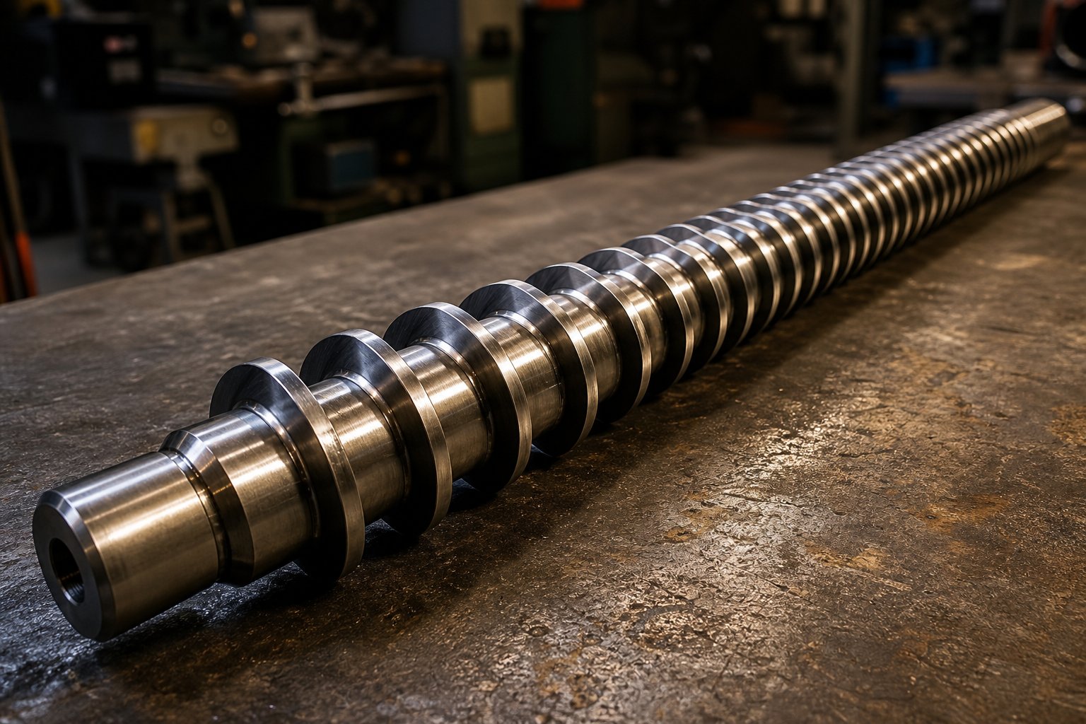
A single screw extruder screw is a helical-flighted metal shaft that rotates inside a heated cylindrical barrel to convey, melt, mix, and meter thermoplastic material into a continuous, pressurized melt stream. Raw polymer—typically in pellet or powder form—enters through a hopper at one end, and the screw's rotation drives that material forward through progressively changing channel geometries until a homogeneous melt exits through a die at the opposite end.
Engineers often call this component the "heart" of the extrusion line, and the analogy holds up well. Just as a heart's chambers and valves dictate blood flow, the screw's geometry—its channel depths, flight angles, and compression profile—dictates how efficiently polymer transforms from solid granules into a uniform, pressurized melt. Every other piece of equipment on the line, from barrel heaters to downstream calibration tanks, responds to what the screw delivers. When screw design is right, the entire process runs predictably. When it's wrong, no amount of downstream adjustment can fully compensate.
As the most popular type of extruder in the plastics industry, single screw machines owe their dominance to relative simplicity, lower capital cost, and the ability to produce continuous output across a wide range of products—pipes, films, sheets, profiles, and wire coatings. Yet that simplicity is deceptive. The screw's performance depends on a precise interplay of geometry, metallurgy, and processing conditions that demands real engineering understanding.
Why Screw Design Matters for Extrusion Performance
Here's something that surprises many operators: the screw does far more than push plastic forward. It simultaneously acts as a solids conveyor, a heat exchanger, a mixer, and a melt pump. The geometry of a single screw extruder screw directly controls four critical performance variables:
- Output rate — how many kilograms per hour of finished product the line produces.
- Melt temperature — how much viscous shear heating the screw adds beyond what the barrel heaters supply.
- Melt quality — the homogeneity of temperature, composition, and pressure across the melt stream.
- Energy efficiency — the specific energy (kWh/kg) consumed to convert raw resin into extrudate.
Change a single parameter—say, the depth of the metering channel by a fraction of a millimeter—and you'll shift the balance among all four. A deeper channel boosts throughput but may sacrifice melt uniformity. A shallower channel improves mixing but can drive melt temperatures beyond the polymer's safe processing window. Every dimension on the screw represents a deliberate engineering trade-off.
The screw is not merely a conveying device—it is a precision heat exchanger, mixer, and pump whose geometry dictates the quality and economics of every extruded product.
That principle is exactly why a generic, one-size-fits-all screw so often underperforms. And it's why the geometry details—zone by zone, flight by flight—matter far more than most operators realize. The sections ahead break down those details, starting with the three functional zones that every extruder screw relies on to transform solid pellets into a production-ready melt.
The Three Functional Zones of an Extruder Screw Explained
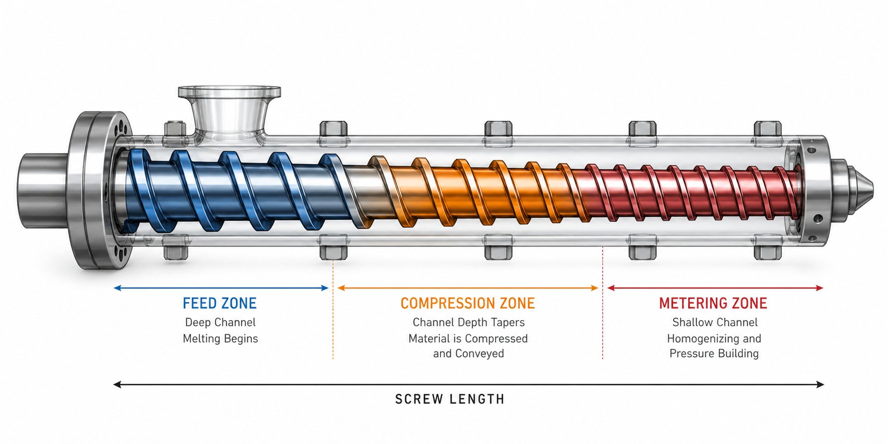
Every single screw extruder screw divides its working length into three distinct regions, each engineered to handle a specific phase of polymer transformation. Think of it like a relay race: the feed zone picks up the baton of raw pellets, the compression zone melts and densifies them under increasing pressure, and the metering zone delivers a uniform melt stream to the die. If any one zone underperforms, the entire line feels it—through reduced output, inconsistent melt quality, or excessive energy draw.
Understanding what each zone does, and how its channel geometry drives that function, gives you the foundation for diagnosing problems and specifying better screw designs. Let's walk through them one at a time.
Feed Zone — Solids Conveying and Intake
The feed zone is where everything begins. Pellets or powder drop from the hopper into the screw channel, and the screw's rotation drags them forward toward the heated barrel. The channels here are deep and maintain a constant depth—deliberately oversized compared to the rest of the screw—so they can accept a large volume of loosely packed solid particles.
How does the material actually move forward? It comes down to friction. The polymer must grip the barrel wall more than it grips the screw root. When frictional drag against the barrel surface exceeds the retarding friction on the screw, the solid bed slides forward along the helical channel. This is why barrel surface condition and feed zone temperature control matter so much. Too much heat at the feed throat can prematurely soften pellets, causing them to stick to the screw root and slip rather than convey. Too little friction at the barrel wall starves the downstream zones of material.
In a typical general-purpose design, the feed zone spans roughly the first 4 to 8 diameters of screw length, though this proportion shifts depending on the polymer and the overall L/D ratio. As Allan Griff's Plastics Extrusion Operating Manual notes, the portion of the screw directly under the feed opening is sometimes excluded from L/D calculations, though many practitioners count it for convenience. Regardless of how you measure, the feed zone's job is singular: pack and push solids forward at a rate high enough to keep the downstream metering channel full and pressurized.
Compression Zone — Melting and Transition
As the solid bed leaves the feed section, the channel depth begins to decrease gradually. This is the compression zone—often called the transition zone—and it's where the real transformation from solid to melt takes place.
Imagine squeezing a handful of plastic pellets inside a progressively tightening space. The decreasing channel depth compacts the loose solid bed, forces out trapped air back toward the hopper, and presses the polymer firmly against the hot barrel wall. A thin melt film forms at the barrel surface, and shear between the rotating screw flight and the stationary barrel continuously wipes this film away, exposing fresh solid material for further melting. This mechanism—known as drag-induced melting—is the dominant mode of phase change in a single screw extruder screw.
The compression ratio governs how aggressively this zone works. It's defined as the ratio of the feed channel depth to the metering channel depth. Typical values range from about 2:1 to 4:1, depending on the polymer being processed. A deep-dive analysis by Mark Spalding at Dow illustrates this vividly: polystyrene performs best at a compression ratio near 3.0, while ABS runs optimally around 2.5. Set the ratio too low and you'll fail to compact the solid bed fully, allowing entrained air to reach the die and cause splay defects. Set it too high and you risk overfeeding the metering section, generating solid fragments that can plug downstream mixing elements and destabilize pressure.
Getting the compression zone right is a balancing act. It must densify and melt the polymer thoroughly—without generating so much viscous heat that temperature-sensitive resins begin to degrade—all within a limited number of screw diameters.
Metering Zone — Pumping and Homogenization
By the time material reaches the metering zone, it should be fully or nearly fully molten. Here, the channel depth is once again constant, but much shallower than in the feed section. This shallow, uniform channel acts as a precision melt pump, generating the stable pressure needed to push polymer through the die at a consistent rate.
Why does metering depth matter so much? Because it's the primary variable controlling shear rate within the melt. A shallower metering channel increases shear, which improves thermal and compositional homogeneity—but it also adds viscous dissipation heat and limits volumetric throughput. A deeper metering channel lets you push more material per revolution, yet the melt may emerge with temperature gradients and uneven mixing. The metering zone depth is, in many ways, the single most consequential dimension on the entire screw.
The metering zone also determines how effectively the screw resists backflow. Melt pressure at the screw tip creates a pressure-driven reverse flow—called pressure flow or leakback—that opposes the forward drag flow. A well-designed metering section balances these competing flows to deliver a steady, pulsation-free output to the die. When you notice surging on the line—rhythmic fluctuations in extrudate thickness or die pressure—the metering zone's geometry relative to die resistance is often involved.
Quick-Reference Zone Comparison
The table below summarizes the three zones side by side, providing a scannable reference for engineers evaluating or specifying screw designs.
| Screw Zone | Primary Function | Channel Depth Characteristic | Key Performance Role |
|---|---|---|---|
| Feed Zone | Solids conveying and intake | Deep, constant depth | Accepts pellets/powder from the hopper and moves them forward via frictional drag against the barrel wall |
| Compression Zone | Melting, densification, and air expulsion | Gradually decreasing depth | Compacts the solid bed, initiates and completes melting through shear and barrel contact |
| Metering Zone | Melt pumping and homogenization | Shallow, constant depth | Delivers uniform melt pressure and temperature to the die for consistent output |
Each of these zones performs a tightly defined job, yet none operates independently. The feed zone's conveying rate must match the metering zone's pumping capacity, with the compression zone bridging the gap between them. An imbalance—say, a feed section that conveys faster than the metering section can pump—leads to excessive channel pressure, solid-bed breakup, and erratic melt delivery.
Knowing what each zone does naturally raises the next question: how do the specific geometry parameters within each zone—channel depth, compression ratio, flight angle, and L/D ratio—interact to shape the performance trade-offs engineers face with every screw design decision?
Key Screw Geometry Parameters and Their Trade-offs
Screw zones tell you where things happen. Geometry parameters tell you how well they happen—and at what cost. Every dimension on a single screw extruder screw involves a compromise: boost one performance metric and you almost always sacrifice another. The challenge for the engineer isn't maximizing any single variable. It's finding the combination of depths, ratios, and flight dimensions that delivers the best overall result for a specific polymer and process.
Let's break down the most influential parameters one by one, then pull them together into a decision-reference table you can use when specifying or evaluating a screw design.
Channel Depth and Its Effect on Throughput Versus Shear
If you could change only one dimension on a screw, channel depth—particularly in the metering zone—would deliver the most dramatic impact on performance. The relationship is straightforward in concept but full of consequences in practice.
A deeper metering channel increases the cross-sectional area of the flow path. More volume per revolution means higher volumetric throughput. Sounds like an easy win, right? The catch is that a deeper channel also reduces the shear rate the melt experiences. Lower shear means less viscous mixing, less internal heat generation, and a greater risk of temperature gradients across the melt stream. You'll push more material, but it may arrive at the die with poor homogeneity—hot on the barrel side, cooler near the screw root, with unevenly dispersed additives or colorants.
Flip the equation: a shallower metering channel restricts volume but dramatically increases shear rate. The melt gets worked harder, producing better thermal uniformity and more thorough distributive mixing. However, that extra shear work converts mechanical energy into heat. For heat-sensitive polymers, this viscous dissipation can push melt temperatures past the degradation threshold no matter how low you set the barrel heaters.
This is precisely why different polymers demand different metering depths. A high-viscosity HDPE processed on a blown film line benefits from a moderately shallow channel that ensures complete melting and melt uniformity. A thermally sensitive rigid PVC compound, on the other hand, needs a deeper channel to limit shear heating—even though that deeper channel sacrifices some mixing intensity. As GS Extruder's parameter analysis emphasizes, excessively shallow grooves reduce available volume and directly limit extrusion output, while excessively deep grooves compromise mixing and heat transfer uniformity.
The takeaway? Channel depth is not a number you optimize in isolation. It's the fulcrum of a throughput-versus-quality seesaw, and the right balance point depends entirely on the resin and the product requirements.
Compression Ratio and L/D Ratio Trade-offs
Two parameters define the macro-level character of a screw design more than any others: compression ratio and L/D ratio. They're often discussed separately, but in practice they interact constantly.
Compression ratio—the ratio of feed channel depth to metering channel depth—controls how aggressively the screw densifies and melts polymer in the transition zone. A higher ratio squeezes the solid bed harder against the barrel wall, accelerating heat transfer and melting. For semi-crystalline polyolefins with a high heat of fusion, ratios of 3:1 to 4:1 are typical. For amorphous or thermally sensitive resins like PVC, ratios drop to 2:1 or 2.5:1 to keep shear heating under control.
But higher compression isn't free. More compression means more viscous dissipation in the transition zone. You're essentially converting screw-drive energy into frictional heat at a faster rate. For polymers with a narrow processing window—PVC being the classic example—excessive compression generates localized hot spots that trigger degradation before the material even reaches the metering zone. On the other end of the spectrum, too low a compression ratio fails to compact the solid bed fully, allowing pockets of entrained air and unmelted particles to pass into the metering section and ultimately to the die.
L/D ratio—the flighted screw length divided by its outer diameter—determines how much real estate the screw has to accomplish feeding, melting, and metering. Most single screw applications fall in the 24:1 to 36:1 range. A longer screw provides more residence time, more barrel surface area for heat transfer, and more room for mixing elements. That extra length is particularly valuable for polymers that are difficult to melt, for color-critical applications requiring extended mixing, or for vented extrusion where a two-stage screw design must decompress, vent volatiles, and then recompress the melt.
Yet longer screws carry their own penalties. Extended residence time degrades heat-sensitive polymers. Manufacturing and maintaining a higher L/D screw demands tighter tolerances, and structural integrity risks increase—particularly shaft deflection on smaller-diameter screws subjected to high torque. This is exactly why simply specifying the longest available L/D "for safety" can backfire. The right L/D is the one matched to the material's thermal sensitivity and the process's mixing demands, not the maximum the machine can physically accept.
Here's the interaction that matters most: compression ratio and L/D work as a team. A moderate compression ratio spread over a longer transition zone (enabled by higher L/D) achieves the same total densification as a steeper ratio packed into fewer diameters—but with gentler shear and lower peak temperatures. Engineers often use this relationship to process challenging materials: lengthen the screw, moderate the compression gradient, and let time and barrel heat do the work instead of brute-force compression.
Flight Geometry — Helix Angle, Flight Width, and Pitch
Channel depth and compression ratio get most of the design attention, but the flight geometry surrounding those channels quietly shapes conveying efficiency, sealing performance, and energy consumption.
Pitch and helix angle are geometrically linked. Pitch is the axial distance from one flight to the next; helix angle is the angle between the flight and a plane perpendicular to the screw axis. On a standard square-pitch screw—where pitch equals the screw diameter—the helix angle works out to approximately 17.66 degrees (often rounded to 17°41' in practice). This angle is popular because, as Allan Griff notes, it makes L/D easy to calculate by simply counting flight turns. More importantly, a square pitch provides a good general-purpose balance between forward conveying force and channel residence time.
Varying the pitch shifts that balance. A wider pitch (higher helix angle) increases the axial conveying component and can boost feed intake, but reduces residence time in each zone. Research cited by GS Extruder's engineering analysis suggests that a 30-degree helix angle maximizes extrusion flow rate theoretically, particularly in the metering zone—while a smaller angle around 15 degrees suits square-shaped granules that benefit from more gradual conveying.
Flight width (also called land width) is the axial thickness of the flight at its outermost edge, typically around 10% of the barrel diameter. The flight land serves as the sealing surface between adjacent channel turns. Wider lands improve the seal and reduce melt leakage (back-flow over the flight tip), but they consume usable channel length and generate more frictional heat in the narrow clearance between flight tip and barrel bore. Narrower lands maximize channel volume and reduce energy losses—but at the cost of increased leakage flow that saps pumping efficiency. Rounded corners at the junction of flight and root prevent polymer stagnation and potential degradation in dead zones.
What often gets overlooked is how these flight parameters interact with channel depth decisions. Widening the groove (the channel between flights) while narrowing the flight land increases channel volume and raises throughput—but simultaneously reduces the screw's resistance to back-flow. The net effect on output depends on how much die-end pressure the screw must overcome. At low head pressures, a wider groove wins. At high head pressures, the leakage penalty can erase the volumetric gain entirely.
Geometry Trade-off Reference Table
The table below consolidates these parameter relationships into a quick-reference tool. For each geometry variable, you'll see the directional effect of increasing that parameter on throughput, shear rate, mixing quality, and melt temperature. Use it as a starting framework when evaluating how a design change will ripple across your process.
| Geometry Parameter | Effect on Throughput | Effect on Shear Rate | Effect on Mixing Quality | Effect on Melt Temperature |
|---|---|---|---|---|
| Channel depth (metering) — increase | Increases (more volume per revolution) | Decreases | Decreases (less intensive mixing) | Decreases (less viscous dissipation) |
| Compression ratio — increase | Neutral to slight decrease (higher restriction) | Increases in transition zone | Improves melting completeness | Increases (more shear heating in transition) |
| L/D ratio — increase | Can increase (more melting and pumping length) | Neutral (distributed over more length) | Improves (longer residence, more mixing opportunity) | May increase (longer residence adds heat history) |
| Helix angle / Pitch — increase | Increases (greater axial conveying component) | Slightly decreases | Decreases (shorter residence per zone) | Slight decrease |
| Flight width (land width) — increase | Decreases (less usable channel length) | Increases in flight clearance zone | Neutral | Increases (more frictional heat at flight tip) |
Notice a pattern? Nearly every parameter that boosts throughput reduces mixing or melt quality, and nearly every parameter that improves homogeneity adds thermal load. This is the fundamental engineering tension in screw design—and it's why experienced practitioners treat the screw as a package where all dimensions are tuned together, not adjusted piecemeal.
Geometry, of course, only tells part of the story. The same set of dimensions performs very differently depending on the overall screw architecture—whether it's a standard general-purpose design, a barrier screw with a secondary flight for controlled melting, or a screw equipped with specialized mixing elements. Those architectural choices determine whether a good set of numbers on paper translates into good performance on the production floor.
Screw Types from General Purpose to Barrier and Mixing Designs
A perfectly calculated set of geometry parameters still underperforms if the screw's overall architecture doesn't match the job. Two screws can share identical L/D ratios, compression ratios, and metering depths—yet produce dramatically different melt quality—because one uses a single continuous flight while the other separates solid and molten polymer with a secondary barrier flight. The architecture determines how those numbers actually work in practice.
When you're evaluating types of single screw extruder screws, three categories cover the vast majority of real-world applications: general-purpose (GP), barrier, and mixing designs. Each solves a different bottleneck, and choosing the wrong one creates problems that no process adjustment can fix.
General-Purpose Screws and Their Limitations
The general-purpose screw—also called a conventional or three-zone screw—is the workhorse of the industry and the most common type in service worldwide. It uses a single continuous flight to perform all three functions: feeding, compressing, and metering. Its appeal is straightforward: lower manufacturing cost, broad material compatibility, and simple maintenance.
For moderate output rates and straightforward polymers, a GP design does its job reliably. Pipe, profile, and sheet lines processing standard resins at reasonable speeds run well on conventional screws for years.
The trouble starts when you push harder. At elevated screw speeds, a single-flight design reaches its melting capacity ceiling. The solid bed—the compacted mass of unmelted pellets traveling through the compression zone—can fracture and break apart before fully melting. This phenomenon, known as solid bed breakup, sends unmelted fragments into the metering section where they resist further melting because the surrounding melt is a poor heat conductor. The result? Unmelted particles or "gels" in the final product, pressure surging at the die, and inconsistent output. As extrusion authority Jim Frankland explains, solids conveyed past the compression zone become extremely difficult to melt because the process shifts from efficient shear-driven melting to inefficient conductive heating through an insulating polymer melt.
Mixing capability is the other weak spot. A GP screw provides only whatever incidental mixing the helical flow pattern generates—which is minimal. If your application involves colorants, fillers, or additives, a conventional screw almost always leaves visible streaks or uneven dispersion. You can raise barrel temperatures or slow the screw speed to compensate, but you're trading output for quality rather than solving the root cause.
Barrier Screws — How the Barrier Flight Improves Melting Efficiency
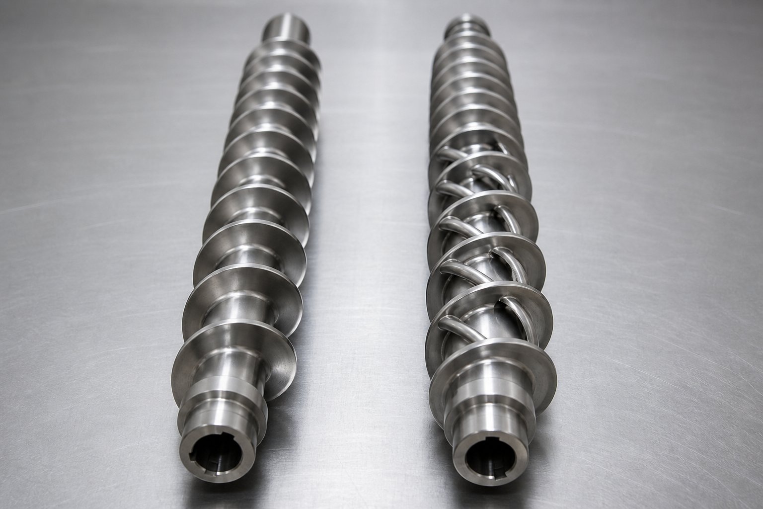
When comparing a barrier screw vs general purpose extruder screw, the key difference is a single structural addition: a secondary flight in the transition zone. This barrier flight has a slightly smaller clearance to the barrel wall than the primary flight, creating two distinct channels—one for the remaining solid bed and one for the accumulating melt pool.
Here's how it works in practice. As polymer melts along the barrel wall, the molten material flows over the barrier flight into the melt channel. Unmelted solids, however, cannot pass through the tighter clearance, so they remain trapped in the solids channel where they continue absorbing heat and shearing against the barrel surface. The solids channel progressively narrows while the melt channel widens, and by the end of the barrier section, the solids channel effectively disappears. The result is that essentially no unmelted polymer can reach the metering zone.
The barrier flight screw melting efficiency advantage is substantial. Because melting is mechanically enforced rather than left to chance, barrier designs deliver more complete melting at higher throughputs, more stable melt temperatures, and dramatically reduced output surging. For high-output HDPE pipe lines, blown film operations, and any application where even a few unmelted particles are unacceptable, barrier screws have become the standard specification.
That said, barrier screws aren't universally superior. They cost more to manufacture, are less forgiving when switching between dissimilar polymers, and require careful geometry matching. A detailed analysis in Plastics Technology cautions that a poorly designed barrier section—one where the compression gradient doesn't match the polymer's actual melting rate—can cause solid fragments to accumulate and plug the end of the solids channel, generating localized forces exceeding hundreds of thousands of pounds. On an 8-inch screw, such forces were estimated at nearly 350,000 pounds, enough to bend the shaft and wear flights down to the root diameter. The takeaway: a barrier screw must be designed for the specific material, not treated as a generic upgrade over a GP design.
Mixing Screws and Specialized Elements
Even a barrier screw that melts polymer perfectly may not disperse colorants, fillers, or additives adequately. That's where dedicated mixing elements come in. These are specialized geometries—typically added near the discharge end of the screw—that force the melt through flow patterns designed to break up agglomerates, redistribute components, or both.
Mixing elements fall into two functional categories. Dispersive mixers apply high shear to physically break apart agglomerates—pigment clumps, gel particles, or incompletely melted fragments. Distributive mixers repeatedly divide and recombine the melt stream to spread components evenly throughout, without relying on high shear. As Plastics Technology's mixing analysis explains, a Maddock mixer is primarily dispersive—melt passes over a narrow clearance under high shear—while pin, Saxton, and pineapple designs are primarily distributive, reorienting the melt with much less shear input.
Choosing the wrong type creates its own problems. A Maddock element on a shear-sensitive PVC compound risks thermal degradation, while a gentle pin mixer on a hard-to-disperse carbon black masterbatch leaves visible agglomerates in the product.
Here's a quick reference of the most common types and their best-use scenarios:
- Maddock (LeRoy) mixer — High-shear dispersive element; best for breaking up pigment agglomerates, gels, and ensuring a final melting check before the die.
- Pin mixer — Low-shear distributive element; ideal for even spreading of additives in shear-sensitive polymers like PVC or temperature-sensitive compounds.
- Pineapple mixer — Moderate-shear distributive element; a versatile middle-ground option for general-purpose blending and color homogenization.
- Blister ring — A restrictive dispersive element that forces melt through a tight annular gap; commonly used as a final screen to trap remaining solid fragments before the metering zone.
- Saxton mixer — Distributive element with helical grooves that split and recombine flow; effective for gentle blending without significant pressure drop.
Many modern high-performance screws combine barrier and mixing sections into a single integrated design—barrier flights handle the melting, and a Maddock or pin section at the discharge end handles dispersion. This combination approach, as engineering analysis confirms, is common for demanding applications like engineering-resin compounding that need both complete melting and thorough additive dispersion. The added cost and application-specific tuning are worthwhile when the alternative is fighting color streaks and melt inconsistency batch after batch.
Screw architecture determines what the screw can accomplish. But the materials the screw itself is made from determine how long it keeps accomplishing it—which is why metallurgy and surface treatments deserve just as much attention as geometry when specifying or evaluating an extruder screw.

Screw Materials and Surface Treatments for Wear Resistance
A perfectly designed screw geometry loses its effectiveness the moment flight surfaces wear down and clearances open up. The material a screw is built from—and the surface protection applied to it—determines whether that geometry holds its precision for months or years. Choosing the wrong extruder screw material is one of the fastest ways to inflate your cost per kilogram of output, because a worn screw silently drains throughput, wastes energy, and degrades product quality long before it actually breaks.
Base Materials — Nitrided Steel and Bimetallic Construction
When evaluating extruder screw material—nitrided steel vs bimetallic—you're really choosing between two fundamentally different protection strategies: hardening the surface of a single steel body, or bonding a wear-resistant alloy layer onto a tough steel core.
Nitrided alloy steel remains the standard for general-purpose extrusion. AISI 4140 and 4340 are the most common base steels for extruder screws. During nitriding—either gas nitriding for shorter screws or ion/plasma nitriding for longer ones—nitrogen diffuses into the steel surface and forms hard nitride compounds, particularly chromium nitrides (CrN), that create a wear-resistant case while the core retains its original toughness and ductility. The result is a screw that resists surface abrasion without becoming brittle throughout its cross-section.
How hard does nitriding make the surface? That depends on the steel grade. Standard 4140 steel achieves moderate surface hardness after ion nitriding, suitable for unfilled commodity polymers. For more demanding applications, specialized nitridable grades like Nit135M and H-13 tool steel can reach surface hardness values exceeding 70 HRC equivalent—hard enough for significantly abrasive processing environments. The nitrided case is also thermally stable, meaning it holds its hardness at the elevated barrel temperatures common in extrusion.
The limitation? Nitrided layers are relatively thin. Once that case wears through, the softer base steel underneath erodes rapidly. For screws processing heavily filled or abrasive compounds, the nitrided case simply doesn't last long enough to justify its lower upfront cost.
Bimetallic construction addresses that limitation head-on. In a bimetallic screw, a wear-resistant alloy—typically a nickel-based matrix embedded with hard carbide particles—is applied to the high-wear surfaces such as flight tops, outer diameters, and root zones. The alloy layer is substantially thicker than a nitrided case, providing a deeper reservoir of protection that extends service life in abrasive environments by a significant margin. As industry comparisons confirm, bimetallic screws outperform nitrided steel in filled plastics, recycled materials, PVC, and wood-plastic composites where abrasive fillers continuously grind against screw surfaces.
Surface Treatments and Coatings for Extended Screw Life
Beyond base material selection, surface treatments and coatings offer targeted protection for specific wear and corrosion scenarios. Think of these as armor plating applied to the zones that take the most punishment. The right extruder screw surface treatment option depends entirely on whether your primary enemy is abrasion, corrosion, or both.
- Hard chrome plating — Provides good corrosion resistance and a low-friction surface finish, making it useful for processing corrosive polymers like PVC. However, chrome plating offers limited abrasion resistance and can exfoliate at elevated temperatures due to mismatched thermal expansion coefficients between the chrome layer and base steel. Best for: corrosion-dominant environments with low abrasive content.
- Nickel-based hardfacing (Colmonoy family) — Welded-on nickel-chromium-boron-silicon alloys that form hard boride and carbide phases. Colmonoy 56 is the workhorse grade at approximately 50-55 HRC, handling standard wear and corrosion duty. Colmonoy 83, which incorporates tungsten carbide particles, pushes hardness above 60 HRC and handles extreme abrasion from glass-fiber-reinforced compounds. Best for: steady abrasive wear from mineral fillers, calcium carbonate, and moderate glass fiber content.
- Cobalt-based hardfacing (Stellite family) — Cobalt-chromium-tungsten-carbon alloys that trade peak hardness for superior toughness and hot hardness. Stellite 6 runs approximately 35-45 HRC, while Stellite 12 reaches about 45-50 HRC. Best for: applications where impact loading or thermal cycling would crack a harder but more brittle nickel-based overlay.
- Tungsten carbide coatings (HVOF or PTA applied) — These coatings deliver very high localized wear resistance by depositing tungsten carbide particles in a metallic binder matrix onto critical screw surfaces. A tungsten carbide coating addresses extruder screw wear in the most severe abrasion zones—flights, roots, mixing sections, and discharge areas. Best for: heavy glass-fiber-reinforced engineering plastics, high-calcium WPC, and heavily filled recycled materials.
- Tool steel and powder metallurgy alloys (CPM 9V, CPM 10V, H13) — Used as full screw body materials rather than coatings when the entire screw surface faces severe wear. These grades offer uniform carbide distribution throughout the material, providing consistent hardness that doesn't wear away in layers. Best for: extremely high glass-fiber content (up to 50-75%) and specialty compounds that destroy conventional screw surfaces.
One important caveat from the hardfacing side: as-deposited hardness values vary depending on application method and dilution—how much base steel mixes into the weld deposit. Treat published HRC numbers as guidance ranges, not absolute guarantees, and verify achieved hardness on the finished screw.
Matching Screw Metallurgy to Your Processing Environment
Selecting the right screw metallurgy for glass filled polymers—or any challenging compound—starts with honestly assessing the wear mechanism your screw actually faces. Hardness alone doesn't guarantee longevity. A screw can have excellent surface hardness yet fail prematurely when its protection doesn't match the specific combination of abrasion, corrosion, and thermal cycling in your process.
Here's a practical framework for matching material to application:
- Unfilled commodity resins (PE, PP, PS, standard ABS) — Nitrided 4140 or 4340 steel provides adequate protection at the lowest cost. These polymers generate minimal abrasive wear, and the nitrided case lasts through normal service intervals without difficulty.
- Corrosive polymers (PVC, fluoropolymers) — Corrosion resistance becomes the priority over abrasion hardness. Nickel-based alloys, bimetallic construction, or hard chrome plating protect against the hydrochloric acid that PVC releases during processing. Standard nitrided steel corrodes and pits rapidly in these environments.
- Moderately filled compounds (10-30% mineral filler or short glass fiber) — Bimetallic screws or Colmonoy 56 hardfaced flights provide the step up in abrasion resistance that nitrided steel can't sustain. The thicker alloy layer absorbs the continuous grinding action of fillers without wearing through to the base steel.
- Heavily filled and glass-fiber-reinforced engineering plastics (30%+ glass-filled nylon, PC, PBT) — This is where tungsten carbide coatings, Colmonoy 83 hardfacing, or powder metallurgy screw materials become essential. Glass fibers are extremely abrasive—harder than most tool steels—and they erode conventional surfaces within weeks of aggressive production.
Screw metallurgy decisions directly impact replacement intervals and total cost of ownership—choosing the cheapest screw upfront almost always proves to be the most expensive option over a production year.
Keep in mind that the screw and barrel must be treated as a matched wear couple. Installing a heavily carbide-armored screw into a soft, worn barrel—or vice versa—creates an imbalanced system where the harder component accelerates wear on the softer one. Both elements should be evaluated together, with compatible hardness levels and coordinated replacement schedules. That screw-barrel relationship, and how it affects everything from clearance to melt quality, is exactly what drives the next critical discussion: understanding the screw and barrel as an integrated system rather than isolated parts.
Matching Screw Geometry to Common Polymer Families
Metallurgy keeps a screw alive. Geometry makes it perform. And geometry that performs brilliantly on polyethylene can produce degraded, streaky, or under-melted product on PVC or glass-filled nylon—even if the screw is brand new. Why? Because every polymer family brings a unique combination of melting behavior, thermal sensitivity, and viscosity characteristics that demands its own set of compression ratios, channel depths, and mixing configurations.
Think of it this way: you wouldn't run the same cutting speed on aluminum and hardened tool steel just because they're both metals. The same logic applies to screw design. The table at the end of this section consolidates the guidance into a single reference, but first, let's walk through the reasoning behind each recommendation family by family.
Polyolefins — PE and PP Screw Requirements
Polyethylene and polypropylene are semi-crystalline polymers with a sharp melting point and a high specific heat of fusion. In practical terms, this means they absorb a large amount of energy during the solid-to-melt transition without softening gradually the way amorphous resins do. As Jim Frankland of Plastics Technology emphasizes, semi-crystalline polymers do not soften at all until very near their melting point—HDPE, for instance, remains rigid until approximately 266°F and then melts sharply.
This melting behavior drives the extruder screw design for polyethylene PE toward higher compression ratios—typically 3:1 to 4:1 according to published material-specific data—because the screw must generate enough compaction pressure and shear energy to overcome that steep heat-of-fusion demand. A low-compression screw simply can't deliver enough energy density in the transition zone to melt a crystalline polyolefin at high throughput. The result? Solid-bed breakup and unmelted particles reaching the die.
The best screw design for PP polypropylene extrusion follows similar logic, with compression ratios ranging from 2.5:1 to 4:1 depending on the grade. Homopolymer PP with high crystallinity sits at the upper end; random copolymers with lower melting points can tolerate more moderate compression.
For high-output polyolefin applications—HDPE pipe lines and blown film are the classic examples—barrier screws are particularly effective. The secondary barrier flight mechanically separates the solid bed from the melt pool, preventing the solid-bed breakup that conventional GP screws suffer at elevated speeds. Pair a barrier section with a Maddock dispersive mixer at the discharge end, and you get both complete melting and a final shear check that catches any lingering fragments. L/D ratios of 24:1 to 30:1 are typical, providing adequate residence time for the high melting energy these resins require.
Amorphous Resins — PVC, PS, and ABS Considerations
Amorphous polymers behave very differently in the screw channel. They soften gradually over a wide temperature range rather than melting at a sharp point, which means they require less compressive force to transition into a processable state. But each amorphous resin introduces its own constraints.
PVC is the most demanding case. Rigid PVC is notoriously thermally sensitive—its degradation temperature sits dangerously close to its processing temperature—so the screw must minimize shear heating at every opportunity. The PVC extrusion screw compression ratio reflects this: industry-standard values for rigid PVC granules run from 2:1 to 3:1, with powder formulations sometimes reaching higher ratios to account for the lower bulk density of the feed. Deep metering channels keep shear rates low, and L/D ratios are often kept shorter (around 20:1 to 24:1) to limit residence time and reduce degradation risk. Mixing sections, if used at all, should be distributive (pin-type or low-shear) rather than dispersive—a high-shear Maddock element on PVC is a recipe for burned material and hydrochloric acid release.
PS and ABS are more forgiving thermally, but they still benefit from thoughtful design. Polystyrene processes well at compression ratios between 2:1 and 4:1, while ABS typically runs best between 1.6:1 and 2.5:1 per published compression ratio tables. Both resins respond well to mixing sections for color dispersion and additive homogeneity—a pin mixer or Saxton element at the screw tip dramatically improves streak-free color consistency in sheet and profile applications without the thermal risk that PVC imposes.
Engineering Plastics and Filled Compounds
Engineering plastics push screw design into more demanding territory. Glass-filled nylon, polycarbonate, and reinforced PBT combine high melting points, narrow processing windows, and—when reinforced—extreme abrasive wear into a single challenging specification.
The screw geometry for glass filled nylon extrusion must balance three competing demands. First, the compression ratio needs to be high enough to fully melt a resin with a steep heat of fusion (PA66 runs at approximately 3.7:1 per published data), but not so aggressive that excessive shear heat pushes past the narrow degradation window. Second, L/D ratios should extend to 28:1 to 32:1, as engineering-plastics guides recommend, to allow complete melting at high melt temperatures and to accommodate vent zones for moisture-sensitive hygroscopic resins. Third, mixing sections must disperse glass fibers without breaking them excessively—shortened fibers reduce the mechanical reinforcement the compound was designed to deliver. Gentle distributive elements outperform aggressive dispersive ones here.
Polycarbonate presents a similar thermal challenge. It processes near 280-310°C with a narrow window between fully melted and degraded, demanding moderate compression (approximately 2.5:1 to 3:1) and sufficient L/D for gradual, controlled melting. PC/ABS alloys inherit polycarbonate's thermal sensitivity and additionally require effective mixing to maintain blend homogeneity.
Polymer-to-Screw Geometry Reference Table
The table below consolidates these recommendations into a practical reference for engineers selecting or specifying screws by polymer family.
| Polymer Family | Compression Ratio Range | Suggested L/D | Mixing Element Needs | Special Considerations |
|---|---|---|---|---|
| HDPE | 3:1 to 4:1 | 24:1 to 30:1 | Dispersive (Maddock) for final melt check | Barrier screw strongly recommended for high-output pipe and blown film |
| LDPE / LLDPE | 3:1 to 3.5:1 | 24:1 to 30:1 | Distributive for additive blending | Lower melt viscosity; deep metering for throughput is common |
| PP (homopolymer) | 3:1 to 4:1 | 24:1 to 30:1 | Distributive or dispersive depending on additives | Higher crystallinity grades need higher compression; barrier beneficial at high speeds |
| Rigid PVC (granules) | 2:1 to 3:1 | 20:1 to 24:1 | Low-shear distributive (pin mixer) only | Extremely heat-sensitive; minimize shear; avoid Maddock elements |
| PS | 2:1 to 4:1 | 24:1 to 30:1 | Moderate distributive for color | Relatively forgiving; broad compression range |
| ABS | 1.6:1 to 2.5:1 | 24:1 to 28:1 | Distributive for color and additive dispersion | Low compression; benefits from mixing more than compression |
| PA (Nylon), unfilled | 3:1 to 3.7:1 | 28:1 to 32:1 | Moderate distributive | Hygroscopic; vented two-stage screw recommended for moisture removal |
| PA (Nylon), glass-filled | 3:1 to 3.5:1 | 28:1 to 32:1 | Gentle distributive (preserve fiber length) | Requires bimetallic or carbide-coated screw; most abrasion-demanding application |
| PC | 2.5:1 to 3:1 | 28:1 to 32:1 | Moderate distributive | Narrow processing window; hygroscopic; venting beneficial |
| Reinforced polyester (PBT/PET) | 3.5:1 to 3.7:1 | 28:1 to 32:1 | Gentle distributive | Abrasion-resistant metallurgy essential; moisture management critical |
One pattern emerges clearly from this table: semi-crystalline resins consistently demand higher compression ratios than amorphous ones, while engineering plastics consistently demand longer L/D ratios and more careful mixing strategies than commodity polymers. Running any polymer on a screw designed for a different family doesn't just reduce efficiency—it introduces defects that mimic equipment problems, sending maintenance teams chasing issues that no repair or adjustment can fix.
Of course, even a perfectly matched screw geometry degrades over time. Flights wear, clearances open, and the effective compression ratio drifts from its original specification. Knowing how to measure that wear—and when it has crossed the line from acceptable to costly—is the difference between planned maintenance and unplanned production losses.
How to Diagnose Screw Wear and Know When to Act
Wear doesn't announce itself with flashing lights or alarm bells. It creeps in gradually—a fraction of a millimeter at a time—until one day you notice the line needs higher screw speeds to hold the same output, melt temperatures drift above setpoints despite stable barrel heaters, and product dimensions start wandering outside tolerance. By that point, you've already been paying for the wear through lost capacity, wasted energy, and rejected product. The question isn't whether your screw will wear. It's whether you'll catch it early enough to act on your own schedule instead of being forced into an emergency shutdown.
Knowing how to measure extruder screw wear—and what the numbers actually mean—turns screw maintenance from guesswork into a data-driven economic decision. Here's how to do it right.
Measuring Flight Diameter and Acceptable Tolerances
The single most important measurement on a worn screw is the outer flight diameter. As the screw rotates inside the barrel, the flight tips—the outermost edges that nearly contact the barrel bore—take the brunt of abrasive and adhesive wear. Over time, the flight outside diameter shrinks while the barrel bore diameter grows slightly, widening the radial clearance between the two. That growing gap is where your output silently disappears.
Why does clearance matter so much? Because melt pressure in the metering zone pushes molten polymer backward over the flight lands. The volumetric leakage rate across that clearance is proportional to the cube of the radial gap—double the clearance and the back-leakage increases roughly eightfold. That's melt your screw already worked to pressurize, flowing backward instead of forward through the die. The result: lower output at the same RPM, higher specific energy consumption, and increased shear heating as leaked melt gets reworked.
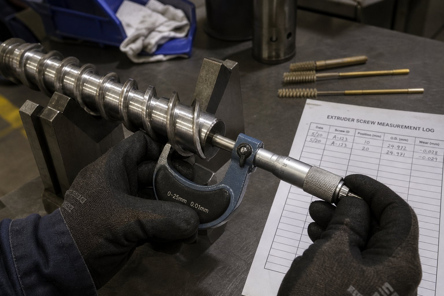
How to take the measurement: Pull the screw during a scheduled maintenance window and thoroughly clean all solidified polymer from the flight surfaces. Davis-Standard's maintenance guidance is emphatic on one point—use only brass tools and copper gauze for cleaning. Steel wire brushes and aggressive abrasives damage the flight surfaces and give you false readings. Once the screw is clean, measure the outer flight diameter at multiple points along the screw length using an OD bar micrometer—a specialized micrometer modified with a bar that spans across the flights to reach the true outer diameter rather than catching on the screw root. Record each reading alongside its axial location so you can map where wear is concentrated.
Compare each measurement against the nominal barrel bore diameter (confirmed with a bore gauge on the barrel itself) to calculate the actual radial clearance at each point. Remember: clearance is the sum of screw wear and barrel wear, so you must measure both components to get the real picture.
What clearance is acceptable? The industry's most widely referenced rule of thumb comes from BLOOM Engineering's wear analysis: as-new flight clearance is approximately the screw diameter divided by 1,000, per side. For a 90 mm screw, that's about 0.09 mm per side; for a 120 mm screw, roughly 0.12 mm. The general replacement threshold is when clearance reaches approximately twice the as-new value. For that 90 mm screw, you're looking at roughly 0.18 mm per side as the point where performance degradation becomes significant.
Another way to frame the same guideline: total diametrical clearance beyond about 0.8-1.0% of the nominal screw diameter signals that wear has reached a level requiring action. Davis-Standard publishes diametrical wear charts categorized into low, medium, and high severity for various screw sizes, with the low threshold indicating the onset of noticeable output decline, the medium threshold signaling that rebuild or replacement planning should begin, and the high threshold marking the point where immediate action is necessary.
Here's the nuance most quick answers miss: "acceptable" depends on what you're producing. A corrugated drainage pipe line may tolerate clearance well past the 2x threshold without visible product issues. A medical tubing line or precision blown film operation may need replacement right at—or even before—that point, because it cannot absorb the output variation and melt-quality drift that worn clearances introduce.
A roughly 10% decrease in screw OD can cut output by as much as 25%—wear quietly steals a quarter of your capacity before the screw physically fails.
Inspecting Root Diameter and Flight Lands for Wear Patterns
Flight OD measurement tells you how much clearance has opened. But the pattern of wear across the screw tells you why it happened—and whether your process conditions are accelerating damage beyond normal rates.
Flight land wear is the most common pattern. The flight land—the flat top surface of the flight tip—bears directly against the barrel bore through a thin polymer film. In normal operation, you'll see even, polished wear across the full width of the land. This indicates the screw is running concentrically in the barrel and wearing at a predictable rate. If the wear is heavier on one side of the land than the other, or concentrated on the "push" side of the flight (the leading face that drives material forward), suspect screw deflection or misalignment between the gearbox and barrel. Metal-on-metal contact from misalignment drastically accelerates wear and can damage both the screw flights and the barrel liner simultaneously.
Root diameter erosion is more insidious. When the root surface—the cylindrical core between flights—wears down, the effective channel depth increases. That might sound harmless, but it directly changes the screw's compression ratio. A screw designed with a 3.5:1 compression ratio that loses root material in the metering zone effectively operates at a lower ratio, reducing melting efficiency and destabilizing pumping. Erosion at the root is particularly common when processing highly abrasive compounds like glass-fiber-filled nylon or heavily filled recycled materials, where filler particles continuously scour the channel floor.
Localized corrosion and pitting often appear first in the compression and metering zones, where temperatures are highest and corrosive decomposition products are most concentrated. PVC processing is the textbook example: hydrochloric acid released during thermal degradation attacks unprotected steel surfaces, creating pits and rough spots that accumulate stagnant polymer. That stagnant material degrades further, producing more acid, creating deeper pits—a self-reinforcing cycle. If you see pitting concentrated in the compression zone, it typically indicates that shear heating is pushing the polymer past its degradation temperature in that region. Pitting confined to the metering zone may point to excessive residence time or dead spots in the flow channel.
Scoring and galling—deep longitudinal grooves on the flight lands or root—indicate that hard contaminants (tramp metal, heavily carbonized degradation products, or oversized filler particles) have been dragged through the clearance gap. This pattern frequently appears after cold-start incidents where the screw was rotated before the polymer was fully melted, placing extreme mechanical loads on the flights and barrel.
Each wear pattern is diagnostic. Even, gradual flight-land wear is normal operational life. Asymmetric wear, root erosion, corrosion pitting, and scoring all point to correctable process or setup issues that, if addressed, extend the next screw's useful life significantly.
When to Rebuild Versus Replace a Worn Screw
Once measurements confirm that your screw has reached or exceeded its wear limit, you face a practical fork in the road: rebuild the existing screw or invest in a new one. The right answer depends on the screw's current physical condition, its service history, and what you need it to deliver going forward.
Criteria favoring a rebuild (refurbishment):
- Flight land wear is the primary issue, with flight OD reduction within a rebuildable range (typically 2-3 mm of flight height reduction).
- Root diameter remains at or very close to original specification—no significant channel depth change.
- Base metal integrity is intact with no cracks, deep pitting, or metallurgical damage from overheating.
- The screw has not been previously rebuilt more than two times. Industry practice limits rebuilds to approximately three cycles, because repeated welding gradually deteriorates the base metal and increases the risk of delamination between hardfacing and the substrate.
- The existing screw geometry still matches your current polymer and process requirements—you're restoring the original design, not trying to change it.
A typical rebuild involves re-hardfacing the worn flight lands with wear-resistant alloy (Stellite or Colmonoy families), then precision-grinding back to original OD specifications. Costs generally run 50-75% of a new screw, making it an attractive option when the base screw is fundamentally sound.
Criteria favoring full replacement:
- Root diameter has eroded significantly, changing the effective compression ratio beyond its design intent.
- Cracking is present along flight roots, on the shank, or at stress concentration points—a structural integrity issue that welding cannot reliably repair.
- Heavy, widespread corrosion or deep pitting has compromised the base metal across large sections of the screw.
- The screw has already been rebuilt two or three times, and the base metal is approaching its metallurgical limits.
- You need to change the screw's design—different compression ratio, barrier flights, mixing elements—to match a new polymer or higher throughput target. A rebuild restores an old design; only a new screw delivers a new one.
One mistake that's surprisingly common: installing a freshly rebuilt or brand-new screw into a worn barrel. Since clearance depends on both components, a new screw in a worn barrel still operates with excessive gap—and the harder new flight tips may actually accelerate barrel bore wear. Always measure the barrel bore alongside the screw, and treat them as a matched pair when making rebuild-or-replace decisions.
Above all, remember that the decision to act is itself an economic one. Every hour a worn screw runs, it consumes more energy per kilogram of output, produces lower throughput at a given RPM, and delivers less consistent melt quality to the die. The cost of continuing to operate a degraded screw almost always exceeds the cost of a planned rebuild or replacement—the difference is simply that production losses are hidden in the daily numbers while a new screw shows up as a line item on the capital budget.
Screw condition, of course, is only half of the wear equation. The barrel bore, heating zone configuration, and screw-barrel clearance interact as a system—and evaluating the screw in isolation without considering its partner component leads to incomplete diagnoses and suboptimal solutions.
The Screw-Barrel System and Why Integration Matters
You've just pulled a screw for inspection, measured the flights, confirmed they're within tolerance, and reinstalled it with confidence. Yet output is still down 8%, melt temperature still runs 15°F above setpoint, and the line still surges every few minutes. What gives? The answer is almost always the same: you evaluated only half the system. A single screw extruder screw never operates alone—it functions inside a barrel whose bore condition, heating zone configuration, and thermal profile directly shape every performance metric the screw delivers. Treating these as separate components is like tuning a piston without checking the cylinder it rides in.
How the Screw and Barrel Work as an Integrated Unit
Imagine squeezing toothpaste through a tube. The force you apply matters, but so does the tube's inner diameter, its wall stiffness, and whether the cap is fully open or partially blocked. The screw-barrel relationship works on the same principle—screw geometry generates the pumping action, but the barrel defines the container that geometry works within. Barrel bore diameter sets the reference for every critical clearance. Barrel heating and cooling zone configuration determines the thermal energy available at each stage of the process. And barrel wear condition decides whether the screw's carefully designed compression ratio and channel depths still produce the intended effect.
One of the most misunderstood aspects of single screw barrel system integration is how barrel temperature affects screw performance in practice. Many operators assume the barrel heaters are the primary source of melt energy. The reality, as extrusion process research confirms, is more nuanced: melting in a single-screw extruder occurs primarily through shear heating—the mechanical energy the rotating screw imparts to the viscous polymer—rather than through direct heat conduction from the barrel wall. Polymers are excellent insulators. Heat from the barrel must first pass through the melt layer in the screw channel before it reaches the solid bed, and that conduction path is inherently slow and inefficient.
So what role do barrel heaters actually play? They establish the thermal boundary conditions that enable shear-driven melting to work. In the feed zone, barrel temperature controls the friction coefficient between the polymer and the barrel wall—too cold and the pellets won't grip; too hot and they stick to the screw root instead of conveying forward. In the compression zone, barrel heat supplements shear energy to maintain the thin melt film on the barrel surface where drag-induced melting occurs. In the metering zone, barrel temperature fine-tunes the final melt temperature around the setpoint established primarily by viscous dissipation.
The ratio of shear heating to conducted barrel heat shifts depending on screw geometry. As Paul Murphy Plastics' analysis notes, larger screws with deeper channels rely more heavily on shear heating because the conduction path from barrel wall to screw root is longer. Smaller screws with shallower channels receive a proportionally larger contribution from barrel heat. This is why the same barrel temperature profile can produce very different melt temperatures on two screws with different metering depths—the barrel's thermal contribution is geometry-dependent, not fixed.
A typical single-screw extruder uses 4 to 8 independently controlled barrel heating and cooling zones. Under stable operation, each zone maintains its setpoint within approximately ±2-3°F, and heater duty cycles hold steady at 40-70%. When those relationships start drifting—Zone 3 creeping above its historical average while adjacent zones remain stable, for example—it signals a change in the heat transfer profile. That change might stem from heater band degradation, thermocouple drift, or barrel bore wear altering the contact relationship between melt and barrel wall. In every case, the barrel condition is changing what the screw "sees," even though the screw itself hasn't moved a micron.
Screw-Barrel Clearance and Its Impact on Performance
If there's a single number that captures the health of the screw-barrel system, it's the radial clearance between the outer flight diameter and the inner barrel bore. This gap—measured in hundredths of a millimeter—determines pumping efficiency, energy consumption, and melt quality in ways that are disproportionate to its tiny physical size.
When clearance is tight and within specification, the flight tips form an effective seal between adjacent channel wraps. Forward-pumped melt stays forward. Pressure builds efficiently in the metering zone, and the screw converts motor energy into output with minimal waste. The screw and barrel clearance effect on extrusion performance is positive: consistent throughput, stable die pressure, and predictable melt temperature.
When clearance opens up—from flight wear, barrel bore enlargement, or both—melt leaks backward over the flight lands. This backflow, called pressure flow or leakback, works directly against the forward drag flow the screw generates. The volumetric leakage rate is proportional to the cube of the radial gap, so even modest wear creates outsized consequences. A clearance increase from 0.10 mm to 0.20 mm per side doesn't double the leakage—it increases it roughly eightfold.
The practical symptoms are unmistakable:
- Reduced output at the same RPM — the screw is pumping, but an increasing fraction of its work leaks backward instead of reaching the die.
- Higher specific energy consumption (kWh/kg) — leaked melt gets reworked by the screw, adding viscous heating without contributing to forward flow. You're paying for energy that produces heat instead of product.
- Elevated melt temperature — the reworked polymer absorbs additional shear energy each time it recirculates, driving melt temperature above setpoints regardless of barrel heater settings.
- Melt pressure instability — predictive maintenance data shows that as screw or barrel wear progresses, melt pressure variation at the adapter increases and output at rated RPM drops below 85% of baseline—a clear signal that the wear couple has reached its functional limit.
This is exactly why an extruder screw barrel wear couple assessment must evaluate both components together. Installing a new screw into a worn barrel—or a freshly relined barrel with a worn screw—still leaves excessive clearance on one side of the equation. Worse, mismatched hardness between a hard new component and a soft worn one can accelerate wear on the softer partner, shortening the overall system life. The recommended practice is to measure both screw flight OD and barrel bore ID at the same maintenance interval, compare them against each other, and plan rebuild or replacement as a coordinated pair.
Reference clearance values scale with screw diameter. Industry guidelines provide the following ranges for new screw-barrel sets:
| Screw Diameter (mm) | Recommended Radial Clearance (mm) |
|---|---|
| 25-45 | 0.08-0.12 |
| 50-80 | 0.10-0.18 |
| 90-150 | 0.12-0.25 |
| 160-250 | 0.18-0.30 |
When actual clearance exceeds roughly twice these as-new values, pumping efficiency has degraded enough to justify action. The exact threshold depends on your product tolerances and energy cost sensitivity, but the underlying physics is unforgiving: clearance wear accelerates exponentially in its effect on leakback, making delayed action progressively more expensive.
Connecting Screw Output to Die and Downstream Equipment
The screw-barrel unit doesn't exist in a vacuum—it's the engine feeding everything downstream. The die, calibration equipment, cooling tanks, and take-off systems all depend on what the screw delivers: a melt stream of consistent pressure, temperature, and homogeneity. When the screw-barrel system degrades, the consequences cascade forward through the entire line.
Screw design must generate sufficient and stable pressure to overcome the flow resistance of the die. Every die has a characteristic pressure drop determined by its land length, gap width, and flow channel geometry. If the screw can't build and maintain the required pressure—because of worn clearances, mismatched metering depth, or insufficient L/D—the melt arrives at the die under-pressurized and at uneven flow rates. The resulting extrudate shows wall thickness variation, surface roughness, or dimensional drift that no amount of die lip adjustment can fully correct.
Melt temperature uniformity from the screw also directly impacts downstream performance. Calibration sleeves and vacuum tanks for pipe extrusion, for instance, are set up for a specific melt temperature and viscosity. When the screw delivers a melt stream with temperature gradients—hotter near the barrel wall, cooler near the root—the extrudate behaves inconsistently in the cooling stage. Some sections solidify faster than others, creating residual stress, warpage, or uneven wall thickness. Similarly, blown film operations depend on uniform melt temperature to maintain a stable bubble. Temperature variations from the screw translate into gauge bands that no air ring adjustment can eliminate.
Melt pressure at the adapter—the junction between the barrel and the die—serves as the single most informative diagnostic of this entire system relationship. Stable pressure with variation under ±50 PSI during steady-state operation indicates a healthy screw-barrel-die system. Gradual pressure decline at constant RPM signals screw or barrel wear. Periodic pressure oscillation (surging) points to solid-bed instability in the screw's compression zone. And sudden pressure rise may indicate screen pack loading or die blockage. Each pattern tells a different story, but all of them trace back to how well the screw-barrel unit is generating and maintaining melt flow.
Optimizing the screw in isolation without considering the barrel condition, heating zones, and die resistance leads to suboptimal extrusion performance.
This systems perspective is exactly why leading screw and barrel suppliers engineer these components as matched pairs rather than interchangeable parts. Manufacturers like NANHAIYA approach the screw-barrel as an integrated unit, with their single screw barrel solutions designed for pipe, film, sheet, pelletizing, recycling, and general-purpose extrusion lines. In each of these applications, screw-barrel alignment, clearance consistency, and metallurgical compatibility between the two components determine whether a line delivers reliable, efficient output—or slowly bleeds capacity through a worn, mismatched system that nobody thinks to evaluate as a whole.
Recognizing the screw-barrel relationship as a system rather than a collection of individual parts is a critical mindset shift. But understanding the system is only the first step—the practical question most engineers face next is how to select the right screw-barrel combination for their specific polymer, application, and production target.
How to Select the Right Extruder Screw for Your Application
You understand the three functional zones. You know how geometry parameters trade off against each other. You can identify screw types, evaluate metallurgy options, match designs to polymer families, diagnose wear, and think about the screw-barrel relationship as an integrated system. That's a lot of knowledge—but knowledge without a decision framework is just information. What you actually need is a structured process that turns all of it into a purchase order for the right screw.
Selecting an extruder screw isn't a single decision. It's a sequence of interconnected decisions, each one narrowing the field until you arrive at a specification that fits your polymer, your product, your machine, and your production economics. Skip a step or get the sequence wrong, and you end up with a screw that looks good on paper but underperforms on the production floor.
Let's walk through that sequence, then translate it into application-specific guidance you can use immediately.
Step-by-Step Screw Selection Process
How do you move from "we need a new screw" to a fully defined specification? Follow these six steps in order—each one builds on the answers from the previous step, so the sequence matters.
- Identify the primary polymer being processed. This is your anchor decision. Everything downstream—compression ratio, channel depth, mixing configuration, metallurgy—flows from the resin's melting behavior, thermal sensitivity, and viscosity profile. If you run multiple polymers on the same line, identify the most demanding one and design for it. A screw optimized for HDPE's high heat of fusion will handle LDPE and PP acceptably; a screw optimized for LDPE may fail to fully melt HDPE at speed.
- Determine output rate and product quality requirements. What throughput does your line need in kilograms per hour, and what quality standard must the extrudate meet? A corrugated drainage pipe tolerates minor melt-quality variation that would be catastrophic on a medical tubing line. Higher output demands push toward barrier screw designs and optimized metering depths; tighter quality requirements push toward mixing elements and potentially longer L/D ratios.
- Select the appropriate screw type — GP, barrier, or barrier with mixing. For moderate output on forgiving polymers, a general-purpose three-zone screw remains cost-effective. For high-speed polyolefin lines where solid-bed breakup is a risk, a barrier design is essential. For applications requiring color consistency, additive dispersion, or processing of recycled streams with variable composition, combine barrier melting with a discharge-end mixing section. The polymer-to-screw geometry reference table from the earlier section provides material-specific guidance on which architecture fits each resin family.
- Specify geometry parameters based on polymer requirements. With the screw type selected, nail down the numbers: compression ratio, L/D ratio, metering channel depth, and flight geometry. Semi-crystalline polyolefins need compression ratios of 3:1 to 4:1 and L/D ratios of 24:1 to 30:1. Thermally sensitive PVC calls for 2:1 to 3:1 compression with shorter L/D. Engineering plastics demand extended L/D of 28:1 to 32:1 for complete melting at elevated temperatures. These aren't arbitrary ranges—they're derived from each polymer's specific heat of fusion, thermal conductivity, and degradation threshold.
- Choose metallurgy and surface treatment based on fill level and polymer corrosiveness. Unfilled commodity resins run well on nitrided 4140 or 4340 steel. Moderately filled compounds (10-30% mineral filler or short glass fiber) step up to bimetallic construction or Colmonoy 56 hardfacing. Heavily glass-reinforced engineering plastics demand tungsten carbide coatings or powder metallurgy screw materials. Corrosive polymers like PVC require nickel-based alloys or chrome plating regardless of fill level. Match the protection to the actual wear mechanism—abrasion, corrosion, or both.
- Evaluate screw-barrel system compatibility. A perfectly specified screw installed into a worn barrel still operates with excessive clearance and degraded pumping efficiency. Confirm that the barrel bore diameter is within tolerance, that barrel liner metallurgy is compatible with the screw's flight hardness, and that barrel heating zone configuration supports the screw's zone layout. If the barrel needs relining or replacement, plan both components together as a matched system.
Notice how each step depends on the one before it. Jumping straight to metallurgy without first confirming the polymer and geometry is like choosing tire compound before you've decided whether you're building a race car or a delivery van. The sequence keeps every decision grounded in the one that matters most: what polymer are you processing, and what does your product demand?
Application-Specific Screw Considerations
The six-step process gives you a universal framework. But real-world extrusion lines don't process polymers in a vacuum—they produce specific products with specific geometric, mechanical, and aesthetic requirements. A single screw design for pipe extrusion vs blown film looks very different even when both process the same HDPE resin, because the die resistance, cooling dynamics, and critical quality metrics diverge sharply.
The table below compares screw design priorities across the most common extrusion application types. Use it alongside the polymer geometry table from the earlier section to cross-reference material requirements with application demands.
| Application Type | Typical Screw Type | Critical Geometry Priorities | Key Performance Metrics |
|---|---|---|---|
| Pipe extrusion | Barrier with dispersive mixer (Maddock) | High compression ratio (3:1-4:1); moderate metering depth for stable pressure; L/D 24:1-30:1 | Melt pressure stability; wall thickness consistency; output rate at target RPM |
| Blown film | Barrier with mixing section | Optimized metering depth for melt temperature uniformity; barrier section tuned to prevent any unmelted particles; L/D 26:1-30:1 | Melt temperature homogeneity; gel-free output; gauge uniformity across the bubble |
| Cast film and sheet | Barrier or GP with distributive mixer | Moderate compression; mixing for additive and color dispersion; L/D 24:1-30:1 | Surface finish quality; color consistency; thickness tolerance across web width |
| Pelletizing and granulation | GP or barrier depending on throughput | High throughput priority; metering depth sized for maximum volumetric output; moderate mixing | Specific output rate (kg/h/RPM); pellet uniformity; energy efficiency (kWh/kg) |
| Recycling | Barrier with strong mixing; often vented two-stage | Extended L/D (30:1-36:1) for volatile removal; robust mixing for variable feedstock; abrasion-resistant metallurgy | Contamination removal; melt homogeneity despite variable input; throughput stability |
Each application places different weight on the throughput-versus-quality trade-off discussed throughout this article. Pelletizing lines prioritize maximum kilograms per hour and energy efficiency. Blown film lines prioritize melt homogeneity above all else—because even microscopic temperature variations translate directly into visible gauge bands in the finished film. Recycling lines face the unique challenge of processing feedstock that varies in composition, contamination level, and bulk density from batch to batch, demanding a screw design robust enough to handle inconsistency without constant manual adjustment.
For manufacturers whose product range spans multiple application types, working with a supplier that covers the full spectrum simplifies specification, procurement, and technical support. NANHAIYA's single screw barrel solutions, for example, are engineered across pipe, film, sheet, pelletizing, recycling, and general-purpose extrusion lines—meaning a single supplier relationship can support the geometry, metallurgy, and clearance requirements for diverse production needs rather than piecing together components from multiple sources with inconsistent quality standards.
Working with Screw and Barrel Manufacturers
Even with a clear selection framework and application-specific guidance, the final specification benefits enormously from collaboration with an experienced manufacturer. Choosing the right extruder screw and barrel manufacturer isn't just about finding the lowest price per unit—it's about finding a partner whose engineering depth matches the complexity of your process.
When you contact a manufacturer, come prepared. The more detailed information you provide upfront, the faster and more accurately they can recommend a solution. Here's what to have ready:
- Polymer data sheets — Resin grade, supplier, melt flow index, filler type and loading percentage, and any additive packages (UV stabilizers, flame retardants, colorants). These drive every geometry and metallurgy decision.
- Target output rates — Your required throughput in kg/h at the intended screw speed range. This determines metering depth, screw type (GP vs. barrier), and whether a mixing section is needed.
- Existing machine specifications — Barrel bore diameter, barrel length, gearbox torque rating, motor power, and maximum RPM. The new screw must physically fit and mechanically match the drive system's capabilities.
- Current barrel condition — Recent bore diameter measurements, liner material, and wear history. A manufacturer who understands the barrel's current state can specify the screw for the actual clearance it will operate in—not an assumed nominal value.
- Current processing issues — Be specific. "Output is low" is less useful than "output dropped 12% over the last six months at the same RPM, melt temperature runs 8°C above setpoint in zones 3-4, and we see occasional unmelted particles in the extrudate." Detailed symptoms help the manufacturer diagnose whether the problem is geometry, wear, metallurgy, or a combination.
- Product specifications and tolerances — Wall thickness ranges, surface finish requirements, dimensional tolerances, and any regulatory standards (food contact, medical, etc.) that constrain material choices or processing conditions.
The value of this preparation goes both ways. A manufacturer who asks probing questions about your process—who wants to understand your polymer, your product, your machine, and your pain points before quoting—is demonstrating the application-specific engineering support that separates a component vendor from a genuine technical partner. If a supplier quotes a screw based solely on diameter, length, and steel grade without asking about your resin or your production challenges, treat that as a red flag. The geometry and metallurgy decisions outlined in this article require real engineering judgment, not catalog lookups.
Ultimately, the right screw for your application is one where every parameter—zone proportions, channel depths, compression ratio, flight geometry, mixing elements, base material, surface treatment, and barrel compatibility—has been chosen deliberately, in the correct sequence, for the specific polymer and product you're producing. Generic screws deliver generic results. A screw specified through the systematic process outlined here, in collaboration with a manufacturer who understands the full system, delivers the output, quality, and efficiency your extrusion line was designed to achieve.
Frequently Asked Questions About Single Screw Extruder Screws
1. What are the three zones of a single screw extruder screw and what does each do?
The three zones are the feed zone, compression zone, and metering zone. The feed zone uses deep, constant-depth channels to accept pellets from the hopper and convey them forward through frictional drag against the barrel wall. The compression zone features gradually decreasing channel depth that compacts the solid bed, expels trapped air, and initiates melting via shear and barrel-wall contact. The metering zone has a shallow, constant-depth channel that acts as a precision melt pump, delivering uniform pressure and temperature to the die. Each zone must be balanced with the others -- if the feed zone conveys faster than the metering zone can pump, solid-bed breakup and pressure instability result.
2. How do I know when my extruder screw needs to be replaced?
The primary indicator is radial clearance between the screw flight outer diameter and the barrel bore. As a widely referenced guideline, new clearance is roughly the screw diameter divided by 1,000 per side, and replacement is typically warranted when clearance reaches approximately twice that value. Practically, a 10% decrease in screw OD can reduce output by as much as 25%. Other signals include rising melt temperatures despite stable barrel heater settings, the need for higher RPM to maintain the same throughput, and visible product defects such as gels or dimensional drift. Always measure both screw flight OD and barrel bore ID together, since clearance reflects combined wear on both components.
3. What is the difference between a barrier screw and a general-purpose extruder screw?
A general-purpose (GP) screw uses a single continuous flight to feed, compress, and meter polymer. It handles a wide range of materials at moderate speeds but is prone to solid-bed breakup and incomplete melting at high throughputs. A barrier screw adds a secondary flight with tighter barrel clearance in the transition zone, creating separate channels for solids and melt. Molten polymer passes over the barrier flight into the melt channel while unmelted solids remain confined for continued heating. This mechanical separation delivers more complete melting, more stable melt temperatures, and higher achievable throughputs -- making barrier screws the preferred choice for demanding applications like HDPE pipe and blown film lines.
4. How does compression ratio affect single screw extrusion performance?
Compression ratio -- the ratio of feed channel depth to metering channel depth -- controls how aggressively the screw densifies and melts polymer. Higher ratios (3:1 to 4:1) generate more compaction pressure and shear energy, which benefits semi-crystalline polyolefins that require significant energy to melt. However, higher compression also increases viscous dissipation and can overheat thermally sensitive resins like PVC, which typically uses ratios of 2:1 to 3:1. The compression ratio also interacts with L/D ratio: spreading a moderate compression gradient over a longer transition zone achieves thorough melting with gentler shear, reducing peak temperatures. Suppliers like NANHAIYA engineer their single screw barrel systems with application-matched compression profiles for pipe, film, sheet, and recycling lines.
5. What screw material should I choose for processing glass-filled polymers?
Glass fibers are extremely abrasive -- harder than most tool steels -- so standard nitrided 4140 or 4340 steel wears through quickly. For compounds with 10-30% glass fiber, bimetallic screw construction or Colmonoy 56 nickel-based hardfacing provides a meaningful step up in service life. For heavily reinforced plastics above 30% glass fill, tungsten carbide coatings applied via HVOF or PTA, Colmonoy 83 with embedded carbide particles, or full powder metallurgy screw bodies (CPM 9V or 10V) become essential. Critically, the barrel liner must match the screw's hardness level -- pairing a carbide-armored screw with a soft barrel accelerates barrel wear. Both components should be specified and replaced as a coordinated wear couple.
Written by
Nanhaiya Technical Team
Zhoushan Nanhaiya Plastic Machinery Co., Ltd.
The Nanhaiya technical team supports screw and barrel manufacturing projects through application review, technical communication, custom manufacturing coordination, and production and quality control.
Discuss Your Application
Related Articles
More insights on screw barrel technology and plastics processing.

What Nobody Tells You About Screw Barrel For Plastic Machine Design
Oct 10, 2026
Learn how screw barrel for plastic machine design affects melt quality, throughput, and wear life. Covers geometry, resin matching, troubleshooting, and sourcing.
Read Article
Single Screw Extruder for Sheet: Stop Guessing, Start Specifying
Oct 9, 2026
Learn how to specify a single screw extruder for sheet production. Covers screw geometry, resin-specific processing, troubleshooting, and maintenance best practices.
Read Article
PE Pipe Extruder Machine: What Datasheets Won't Tell You
Oct 9, 2026
Learn how a PE pipe extruder machine works, key specs explained, material grade selection, maintenance tips, and buyer guidance beyond the datasheet.
Read ArticleLooking for something else?
Search by material, symptom or product and jump straight to the relevant page.
These are navigation suggestions based on keyword matching — not a quotation, not a delivery commitment, and not a substitute for engineering review. Final specification is confirmed by our engineers against your drawings and processed material.
Need help with screw barrel selection?
Share your machine model, processed material and application. Our team can help with pricing and technical support.