

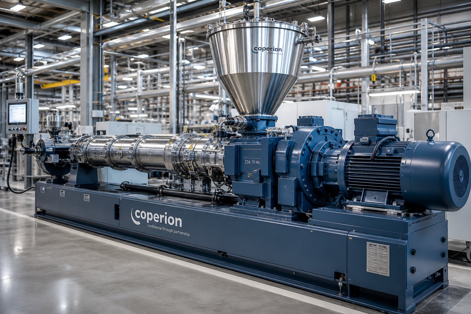
What Is a Single Screw Extruder Machine and Why It Matters
If you work anywhere near plastics manufacturing, you've almost certainly encountered a single screw extruder machine — even if you didn't fully understand the engineering behind it. It looks straightforward: raw polymer goes in one end, a finished shape comes out the other. But between those two points lies a carefully orchestrated interplay of heat, pressure, friction, and screw geometry that determines whether your output is profitable or problematic.
Defining the Single Screw Extruder Machine
At its core, a single screw extruder is a continuous plastics processing system. A single rotating Archimedean screw sits inside a heated barrel, where it melts, mixes, and pushes polymer material — typically fed as pellets, granules, or powder — through a shaped die to produce a constant cross-section product. The melting process relies on a combination of conductive heat from barrel heaters and viscous dissipation, often called shear heat, generated by the mechanical action of the screw itself.
A single screw extruder machine is a continuous processing system that uses one rotating helical screw inside a heated barrel to melt, homogenize, and force thermoplastic material through a die, producing a consistent cross-sectional profile. It is the most widely used type of plastic extrusion machine, forming the foundation of pipe, film, sheet, profile, filament, and pellet production worldwide.
That definition sounds simple, but don't let it fool you. The performance difference between a well-configured extruder and a poorly matched one can mean tens of thousands of dollars in scrap, energy waste, and lost throughput every year.
Why Single Screw Extrusion Dominates Plastics Processing
Why does this particular machine type command such a dominant position? The numbers tell the story. The single screw segment held over 63% of global plastic extrusion machine market share in 2025 — a market valued at USD 7.2 billion and projected to reach USD 10.2 billion by 2033. That dominance traces back to a combination of lower equipment cost, simpler operation, continuous output capability, and straightforward maintenance compared to twin screw alternatives.
You'll find single screw extruders producing everything from HDPE water pipes and PVC window profiles to multilayer packaging films, thermoforming sheets, and 3D-printing filaments. The industries they serve — packaging, construction, automotive, medical, consumer goods, and electronics — represent the broadest cross-section of modern manufacturing. Construction alone accounted for roughly 31.5% of end-use demand in 2025, driven by pipes, insulation, cladding, and door profiles. Packaging follows closely, fueled by growing demand for flexible food, pharmaceutical, and e-commerce solutions.
This isn't a machine that's fading into obsolescence, either. Growing adoption of recyclable plastics, energy-efficient drive systems, and advanced digital controls continues to push the single screw extruder forward as a modern, high-performance platform.
What This Guide Covers
Most supplier brochures give you glossy photos and a spec sheet. This guide goes deeper — into the territory your sales representative probably won't walk you through. Here's what you can expect:
- Core components — a detailed breakdown of every major part, from hopper design and barrel metallurgy to the breaker plate and drive system
- Screw zones and geometry — feed, compression, and metering zones explained with the engineering detail that actually helps you make decisions
- Screw design variants — barrier flights, mixing elements, vented screws, and grooved feed configurations that most articles never mention
- Technical specifications decoded — what L/D ratio, compression ratio, RPM range, and motor power really mean for your production output
- Single screw vs. twin screw comparison — an honest, criteria-based evaluation to help you pick the right architecture
- Material compatibility — how to match screw configuration and barrel lining to your specific polymer family
- Maintenance and troubleshooting — wear patterns, common defects, and the corrective actions that restore line performance
- Selection criteria — a step-by-step framework for choosing the right extruder based on your product, material, throughput, and budget
Whether you're an operator trying to diagnose a surging issue, a process engineer evaluating a new line, or a buyer comparing equipment options, this guide is built to serve as a practical engineering reference you can return to repeatedly. The real value of understanding your extruder isn't academic — it shows up directly in your melt quality, your energy bills, and your reject rate.
That understanding starts with knowing exactly what's inside the machine — and why each component exists in the first place.
Core Components of a Single Screw Extruder Explained
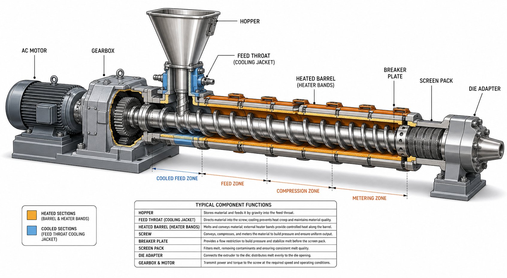
Every screw extruder is ultimately a sum of its parts — and the way those parts interact determines whether you get uniform, high-quality output or a frustrating cycle of scrap and downtime. Supplier catalogs tend to highlight horsepower and throughput, but they rarely explain why a barrel is lined with tungsten-carbide alloy instead of standard nitrided steel, or what the breaker plate actually does beyond "filtering." This section walks through every major component from the feed end to the die, covering the design choices and materials that separate a well-engineered extruder machine for plastic from a commodity box.
Hopper and Feed Throat Design
The hopper is where raw material — pellets, granules, regrind, or powder — first enters the system. It sounds simple: gravity pulls material down into the screw channel. And for many standard pellet-fed applications, a plain gravity-fed hopper works perfectly well. But imagine processing a low-bulk-density powder or a regrind blend with irregular particle shapes. Suddenly, material bridges inside the hopper — it forms an arch above the feed throat and stops flowing entirely. Production halts until someone breaks the bridge manually.
That's why higher-performance designs use force-feeding mechanisms: a crammer feeder or a stuffing auger that actively pushes material into the screw channel. Force feeding is especially critical for processing film flake, fibers, or lightweight recycled material that won't flow reliably under gravity alone.
The feed throat — the short transition section connecting the hopper to the barrel — deserves attention too. It's equipped with a cooling jacket, typically circulating water, for a very specific reason: the barrel immediately downstream is heated to processing temperatures, and that heat conducts backward toward the feed zone. Without active cooling, pellets begin to soften and stick to the feed throat walls, creating a fused plug that chokes throughput. You'll hear experienced operators call this "bridging at the throat," and it's one of the most common yet preventable causes of output inconsistency in a single extruder screw setup.
Barrel Construction and Lining Materials
The barrel is far more than a passive steel tube. It's a precision-bored cylinder that must withstand continuous high pressures, temperatures often exceeding 300°C, and direct chemical and mechanical attack from the polymer melt. Its bore is machined to extremely tight tolerances — the running clearance between screw flight and barrel wall is typically the screw diameter divided by 1,000, per side. For a 90 mm screw, that's less than 0.1 mm. This tiny gap is what makes the pumping mechanism work: tight enough to prevent melt from leaking backward over the flights, just loose enough to avoid metal-to-metal contact.
Standard barrels are forged from alloy steel and then nitrided — a surface-hardening treatment that creates a thin, hard case layer. Nitriding is the economical baseline, suitable for general-purpose extrusion of unfilled commodity resins. But the moment you introduce abrasive fillers like glass fiber, calcium carbonate, or mineral additives, standard nitrided barrels wear out at an alarming rate.
This is where bimetallic barrel linings become essential. A bimetallic barrel features a centrifugally cast alloy liner bonded to the inside of the steel barrel body. Common liner alloys include:
- Iron-boron alloys — provide good general abrasion and corrosion resistance at moderate cost; a solid all-around choice for most filled compounds
- Tungsten-carbide-based alloys — deliver maximum abrasion resistance for heavily glass-filled or mineral-filled materials; significantly extend barrel life in the most demanding applications
- Nickel-based corrosion-resistant alloys — designed for chemically aggressive polymers like PVC (which releases hydrochloric acid) or fluoropolymers
Choosing the right lining isn't a luxury — it's an economic decision. A bimetallic barrel may cost more upfront, but if it lasts three to five times longer than a standard nitrided barrel in your specific application, the cost per operating hour drops dramatically.
The Screw: Metallurgy, Flights, and Surface Treatments
The screw is the single most engineered component in the entire system. Its helical flight cooperates with the barrel bore to form a channel that conveys, compresses, melts, and pumps the polymer. Every dimension matters — flight depth, pitch, width, helix angle, and the transitions between zones all influence output rate, melt quality, and energy consumption.
Most single extruder screws are machined from nitriding steel, commonly 38CrMoAlA or equivalent grades, chosen for a hard surface layer and good core toughness. For more aggressive applications, screw flights can be hardfaced with stellite or tungsten-carbide welding overlays to resist abrasive wear. Some processors opt for hard chrome plating on the screw body to improve corrosion resistance and reduce polymer adhesion — particularly useful for sticky or thermally sensitive resins.
The critical takeaway? The screw and barrel are a matched system. A brand-new screw installed into a worn barrel won't restore performance, because the enlarged bore diameter reopens the leakage path over the flights. Both components must be evaluated together.
Breaker Plate, Screen Pack, and Die Adapter
Here's a component that most articles barely mention — yet it plays three essential roles simultaneously. The breaker plate is a thick, perforated steel disk positioned at the discharge end of the barrel, just before the die. It's riddled with small, precisely drilled holes, and a screen pack — one or more layers of fine wire mesh — sits directly upstream of it.
What does this assembly actually do?
- Converts rotational flow to axial flow. As the melt travels along the spinning screw, it picks up a helical, swirling motion. If that rotational flow enters the die directly, you'll see distortions, warpage, and inconsistent wall thickness in the final product. The breaker plate straightens the polymer melt path, converting spiral flow into parallel, axial streams — ensuring a uniform velocity profile across the die inlet.
- Filters contaminants. The screen pack traps unmelted gels, degraded particles, metal shavings, and other foreign matter before they reach the die. Without it, these contaminants cause surface defects, streaks, and die plugging. The breaker plate provides the structural support that prevents the fine mesh from collapsing or blowing out under the high melt pressures inside the barrel.
- Builds back pressure. The restrictive hole pattern forces the melt to constrict as it passes through, creating head pressure that pushes back against the screw. This back pressure is actually desirable — it increases the shear and mixing action within the screw channel, producing a more thermally and compositionally homogeneous melt.
The die adapter connects the barrel outlet (through the breaker plate) to the die itself. Its geometry — the internal flow channel shape, length, and taper — directly affects how uniformly the melt distributes across the die entrance. A poorly designed adapter creates dead spots where polymer stagnates, degrades, and eventually flushes out as black specks or discolored streaks. Streamlined, coat-hanger-style adapters are preferred for wide dies like sheet and film applications, while simpler conical adapters work for pipe and profile dies.
Drive System and Gearbox
The drive system provides the torque and speed that rotate the screw — and getting it right has a surprisingly large impact on process flexibility. A mismatch between motor, gearbox, and application can limit your line's throughput just as effectively as a worn screw.
Modern extruding equipment typically uses AC motors with variable-frequency drives (VFDs), which have largely replaced older DC motor systems. AC drives offer better energy efficiency, lower maintenance (no brushes to replace), and precise speed control across a wide range. DC motors are still found on older lines and offer excellent low-speed torque, but their maintenance requirements and efficiency penalties make them less attractive for new installations.
The gearbox sits between the motor and the screw, reducing motor speed to the much lower screw RPM while multiplying torque proportionally. Typical gearbox reduction ratios for single screw extruders fall between 10:1 and 20:1, though the exact ratio depends on the application. As Plastics Technology notes, the motor and gearbox should be selected so the extruder operates at roughly 70% of maximum motor current and 70% of maximum screw speed — leaving headroom for future rate increases or processing more viscous resins.
Why does this matter practically? If your gearbox limits maximum screw speed to 120 RPM but your application requires 200 RPM, you're stuck — no screw redesign can compensate. Conversely, a gearbox that provides high speed but insufficient torque will cause the motor to run at maximum current, leaving no room to adjust screw geometry for better melt quality. The lesson: always verify that the drive system matches both your current process and any foreseeable future needs.
Component Reference Summary
| Component | Typical Material of Construction | Primary Function |
|---|---|---|
| Hopper | Stainless steel or carbon steel | Stores and feeds raw material (pellets, powder, regrind) to the screw; may include force-feeding mechanisms for low-bulk-density materials |
| Feed Throat | Cast or machined steel with water-cooling jacket | Channels material from hopper into barrel; cooling prevents premature melting and bridging |
| Barrel | Alloy steel with nitrided bore, or bimetallic lining (iron-boron, tungsten-carbide, or nickel alloy) | Provides the heated, pressure-containing cylinder; transfers conductive heat to polymer; maintains precision bore tolerance with the screw |
| Screw | Nitriding steel (38CrMoAlA or equivalent); optional hardfacing (stellite, tungsten-carbide) or chrome plating | Conveys, compresses, melts, mixes, and pumps the polymer through the barrel via helical flight geometry |
| Breaker Plate | Hardened tool steel or stainless steel | Converts rotational melt flow to axial flow; supports the screen pack; builds back pressure for improved mixing |
| Screen Pack | Woven stainless steel wire mesh (single or multiple layers) | Filters contaminants, unmelted particles, and gels from the melt stream before it enters the die |
| Die Adapter | Tool steel or stainless steel, internally polished | Connects barrel outlet to die; shapes the flow channel to distribute melt uniformly across the die entrance |
| Gearbox | Hardened alloy steel gears; cast iron or steel housing | Reduces motor speed and multiplies torque to deliver the required screw RPM and driving force |
| Motor (Drive) | AC induction motor with VFD (modern) or DC motor (legacy) | Provides rotational power; VFD enables precise, variable screw-speed control across the operating range |
Each of these components contributes to a single outcome: delivering a uniform, well-mixed, pressurized melt to the die at a stable rate. But how the screw's internal geometry — its zones, channel depths, and compression profile — orchestrates the actual melting process is where the real engineering nuance lives. That geometry is where a general-purpose machine becomes one that's truly optimized for your polymer and your product.
Understanding Screw Zones, Geometry, and Classification
The screw's external dimensions — its diameter, length, and flight profile — only tell part of the story. The real performance of a single screw extrusion machine is shaped internally, by the way the screw channel changes depth, width, and character along its length. These changes divide the screw into three distinct functional zones, each designed to handle the polymer in a fundamentally different physical state. Getting these zones right is the difference between smooth, efficient processing and a machine that fights you on every run.
Feed Zone and Solids Conveying Mechanics
The feed zone is the first section of the screw, starting directly beneath the feed throat. Its defining characteristic is a deep, constant-depth channel designed to accept and convey solid polymer pellets or powder toward the hotter downstream zones. No significant melting happens here — the material remains mostly in a glassy or solid state, and the primary job is simply to move it forward efficiently.
Here's where things get counterintuitive. You might assume the screw pushes the material forward by gripping it — but actually, the mechanism relies on a friction differential. Solids conveying works because the friction between the polymer and the barrel wall is higher than the friction between the polymer and the screw root. The barrel "grabs" the material while the rotating screw slides underneath it, pushing the solid plug forward like a nut being driven along a bolt. If the barrel-side friction drops — due to wear, contamination, or incorrect temperature — throughput drops immediately, even though the screw is still turning at full speed.
This friction-dependent mechanism is exactly why grooved feed zone designs exist. By machining axial grooves into the barrel liner in the feed section, manufacturers create a mechanical interlock between the polymer and the barrel wall. Instead of relying purely on friction, the grooves physically grip the pellets, dramatically increasing solids conveyance pressure. Grooved feed barrels are common in high-output polyolefin applications — particularly HDPE pipe and blow molding — where maximizing throughput per screw revolution is a primary goal. The trade-off? Higher feed pressure means higher drive torque requirements and a stiffer process that's less forgiving if operating parameters drift.
The length of the feed zone varies with the polymer type. Crystalline polymers like HDPE and nylon typically need the longest feed sections, followed by rigid amorphous materials like polycarbonate, with soft amorphous polymers like flexible PVC requiring the shortest.
Compression Zone and Melting Dynamics
As the solid plug advances beyond the feed zone, it enters the compression zone — also called the transition zone or melting section. This is where the real transformation happens. The channel depth gradually decreases along the length of this zone, mechanically compressing the material while barrel heaters and shear friction work together to convert it from a solid into a viscous melt.
Imagine squeezing a mixture of ice and water through a progressively narrowing pipe. The constriction forces the components together, generates friction heat, and accelerates the phase change. The compression zone does essentially the same thing with polymer — the shrinking channel compacts the solid bed against the heated barrel wall, where a thin melt film forms. As the screw rotates, it scrapes this melt film off the barrel surface and collects it into a growing melt pool on one side of the channel, while the remaining solid bed is pushed into ever-tighter contact with the hot wall.
The compression ratio quantifies this channel depth change and is calculated simply:
Compression Ratio = Feed Zone Channel Depth / Metering Zone Channel Depth
Typical values range from 2:1 to 4:1, depending on the polymer's bulk density and melting behavior. A powdered resin with lots of entrained air needs a higher compression ratio — perhaps 3.5:1 or 4:1 — to expel that air and compact the material. Pelletized resin with a higher bulk density might only need 2.5:1.
The length of the compression zone matters just as much as the ratio. This is where the distinction between crystalline and amorphous polymers becomes critical. Crystalline polymers like HDPE and PET have a sharp, narrow melting point — they transition abruptly from solid to liquid. A long, gradual compression zone accommodates this behavior, preventing sudden pressure spikes. Amorphous polymers like PS and ABS, on the other hand, soften progressively over a wide temperature range, so they can tolerate — and even benefit from — a shorter, more aggressive compression section. As extrusion processing literature notes, some crystalline materials with a very narrow melting range can use a compression section as short as a single screw pitch, while others need the section to span a significant portion of the screw's total length.
Metering Zone and Melt Homogenization
By the time the polymer reaches the metering zone — the final section of the screw — it should be fully molten. The channel depth here is shallow and constant, forming a uniform annular gap between the screw root and the barrel wall. This shallow geometry serves two purposes: it maximizes shear in the melt to equalize temperature variations, and it builds the consistent pressure needed to push material through the breaker plate and die at a steady rate.
Think of the metering zone as a quality-control section. Any temperature gradients, unmixed regions, or pressure fluctuations that survived the compression zone get worked out here through continued shearing and mixing. The melt flow in this zone is actually a combination of four distinct flow patterns: forward drag flow driven by screw rotation, backward pressure flow caused by die resistance, cross-channel flow that enhances mixing perpendicular to the flights, and a small leakage flow over the flight tips. The balance between forward flow and pressure flow determines the actual output rate — and that balance shifts whenever you change the die, adjust screw speed, or switch materials.
The metering zone's channel depth is a critical design variable. Too deep, and the shear rate drops, producing a poorly mixed, thermally uneven melt. Too shallow, and excessive shear generates too much frictional heat, risking polymer degradation — especially problematic for heat-sensitive materials like PVC. Experienced screw designers for screw extruders tune this dimension carefully, often within fractions of a millimeter, based on the target polymer's viscosity and thermal stability.
Reading the 3-Figure Extruder Classification
When you're comparing screw plastic extruder models across different manufacturers, you'll frequently encounter a standardized three-number designation — something like 1-60-24 or 1-90-30. This classification system, widely referenced in the industry, packs the most essential machine parameters into three numbers. Here's how to decode it:
- First number — Number of screws. A "1" indicates a single screw machine. A "2" would indicate a twin screw extruder. This immediately tells you the fundamental machine architecture.
- Second number — Screw diameter in millimeters. In "1-60-24," the screw is 60 mm in diameter. Diameter is the single most direct indicator of the machine's throughput capacity — larger diameters move more material per revolution. Common single screw diameters range from 20 mm for laboratory units up to 450 mm or more for high-volume production lines.
- Third number — Effective L/D ratio. This is the effective screw length expressed as a multiple of the screw diameter. A value of "24" means the working length of the screw is 24 times its diameter — so for a 60 mm screw, that's 1,440 mm of active processing length. Higher L/D ratios (30:1 to 36:1) provide more residence time and processing length for demanding tasks like venting, intensive mixing, or processing filled compounds. Shorter ratios (20:1 to 24:1) suit straightforward melting of single-polymer systems.
So when you read "1-90-30" on a spec sheet, you instantly know: single screw, 90 mm diameter, with an L/D of 30:1 — giving you 2,700 mm of effective screw length. That's enough information to estimate the machine's approximate throughput class, its suitability for your polymer, and whether it has adequate processing length for your application's complexity.
Here's a practical tip: don't just compare L/D numbers across brands without confirming what "effective length" means to each manufacturer. Some measure from the start of the feed pocket; others from the first full flight. A single screw extrusion machine listed as 30:1 by one supplier might be functionally equivalent to a 28:1 from another. Always ask for the actual measurement basis when doing head-to-head comparisons.
These three zones and the classification system give you the vocabulary to speak precisely about screw geometry. But the standard three-zone design is just a starting point — and for many applications, it isn't enough. Barrier flights, mixing elements, and vented configurations push single screw performance well beyond what a basic feed-compression-metering layout can deliver.
Screw Design Variants Every Operator Should Know
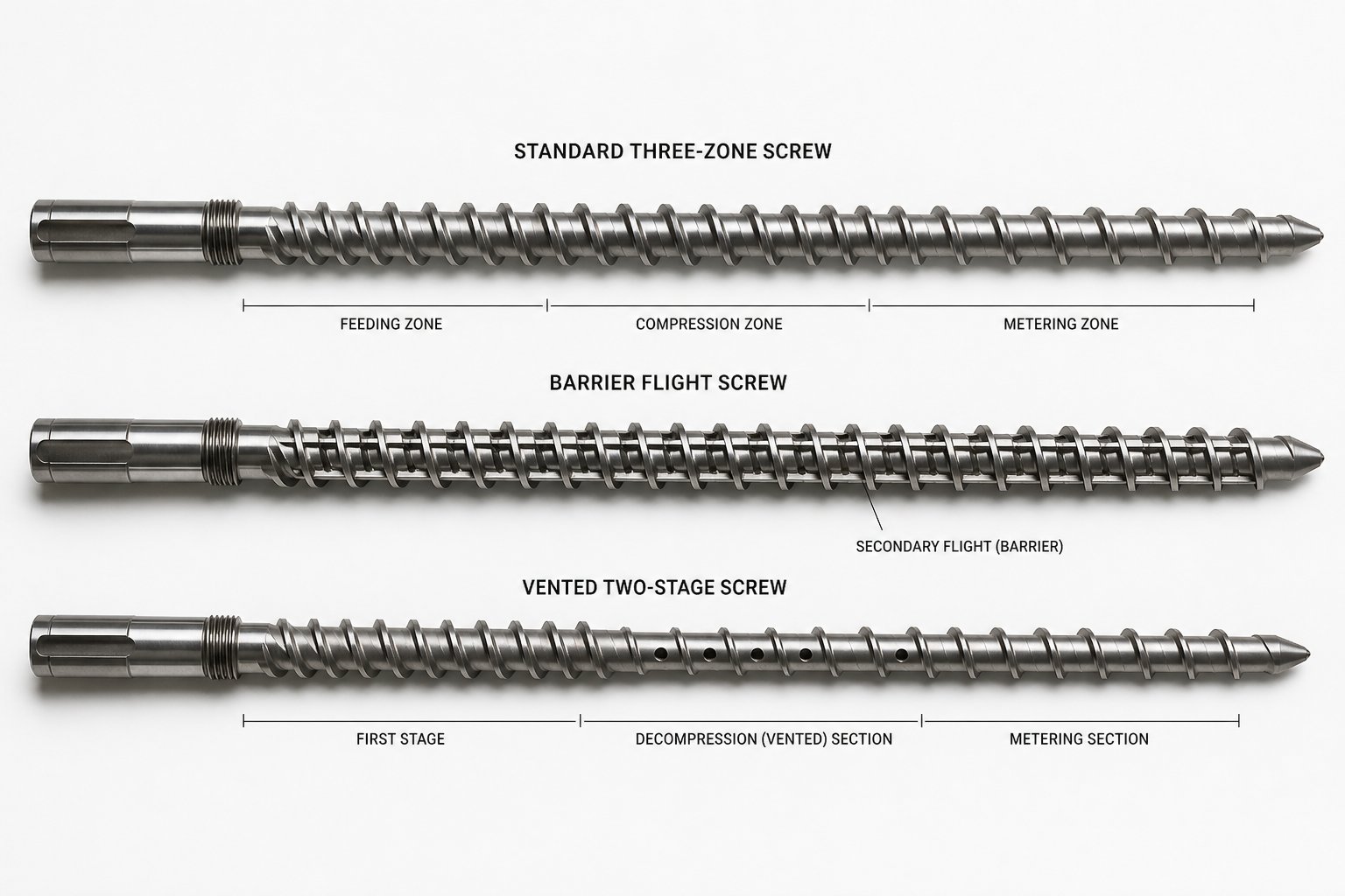
A standard three-zone screw handles a broad range of applications — but it has a ceiling. Push it beyond its melting capacity and you get unmelted particles in your product. Ask it to disperse a color masterbatch and you get streaks. Feed it moisture-laden recycled resin and you get bubbles and surface defects. These aren't problems you can solve by adjusting barrel temperatures or screw speed. They're screw-type problems, and the only real fix is a different screw geometry designed to address the specific limitation.
Most supplier literature — and most competitor articles — skip this topic entirely. Yet choosing the right screw variant for your single screw plastic extruder is arguably the highest-impact design decision you'll make. Here's what's available and when each variant earns its place.
Barrier Flight Screws for Improved Melting
The biggest limitation of a conventional screw is its melting capacity. A single continuous flight does its best to compress and melt the polymer, but at higher output rates or with hard-to-melt crystalline resins, unmelted pellets inevitably slip past the compression zone and contaminate the final product. Barrier flight screws solve this by adding a secondary flight in the compression zone that physically separates the solid bed from the melt pool. As polymer melts against the barrel wall, it flows over the barrier flight into a dedicated melt channel, while unmelted solids are retained in a shrinking solids channel until they too are fully melted. The result? No unmelted material can reach the metering zone — everything must melt to cross the barrier.
Two principal designs dominate the market:
- Maillefer (crossing) barrier screws — one of the earliest designs, where the barrier flight crosses the main flight path. The solids channel narrows smoothly without a sudden geometric change at the start, making this style advantageous for hard or slippery polymers whose fragile solid beds don't easily reshape to accommodate abrupt cross-section changes. Crossing barriers also tend to generate more head pressure due to their wider, shallower melt channel configuration.
- Barr (parallel) barrier screws — introduced later, these feature a barrier flight that runs roughly parallel to the main flight. The key advantage is roughly one-third more surface area in the solids channel compared to a crossing design of the same axial length. Since melting capacity is largely proportional to available surface area, parallel barrier designs deliver higher output with better melt quality for polymers that have higher energy requirements — those with higher melting points, higher specific heats, or greater shear-thinning tendency.
Which one do you need? It depends mostly on the melting requirements of your polymer. A parallel (Barr) type generally works better for polymers with higher melting demands, while crossing (Maillefer) types suit lower-energy polymers and materials with fragile solid-bed formations. Modifications to both — sometimes called Dray-Lawrence types — use longer helix angles to get more volume into the barrier section for higher output, though the improvement in melting capacity per se is modest unless axial length is also increased.
One important caveat: a barrier screw must be designed for your specific material. A generic barrier upgrade can actually worsen performance if the barrier geometry is poorly matched to the polymer's melting rate, leading to solid-bed plugging and the very surging it was meant to eliminate.
Distributive vs Dispersive Mixing Elements
Melting the polymer completely is only half the battle. Many applications demand thorough mixing — whether you're incorporating color concentrate, blending in additives, or distributing mineral fillers uniformly throughout the melt. A standard three-zone screw provides minimal mixing capability, which is exactly why dedicated mixing sections exist.
The critical distinction that every polymer extruder operator should understand is between dispersive and distributive mixing — two fundamentally different mechanisms that address different problems.
Dispersive mixing applies high shear stress to break apart cohesive clusters — pigment agglomerates, unmelted gels, filler clumps — into their primary particle size. Think of it as crushing and grinding. The most common dispersive mixing element is the Maddock mixer (also called a fluted mixer or Union Carbide mixer). It features alternating inlet and outlet flutes separated by a barrier ridge with a tight clearance to the barrel wall — typically 0.020 to 0.030 inches (0.50 to 0.75 mm), as veteran extrusion engineer Allan Griff details. Melt enters the inlet flutes, is forced over the barrier under high shear, and exits through the outlet flutes. Unmelted particles can't pass over whole — they're sheared and flattened until they finally cross as melt. A blister ring works on a similar principle, forcing the entire melt stream through a narrow annular gap for intensive shearing.
Distributive mixing, by contrast, uses low shear to divide, reorient, and recombine the melt stream repeatedly — spreading additives evenly without generating the intense frictional heat that dispersive elements produce. Common distributive elements include:
- Pin mixers — rows of studs projecting from the screw root that disrupt streamlined flow like rocks in a stream, dividing and recombining the melt path. Pins generate the least shear of any mixing element and are ideal for shear-sensitive materials.
- Pineapple mixers — featuring a diamond-cut or intersecting-groove pattern that repeatedly splits and rejoins melt flow with moderate shear. They sit between pin mixers and Maddock elements in intensity.
- Saxton elements — slotted, helical mixing flights that reorient the melt through multiple flow divisions, providing effective distributive mixing with controlled energy input.
Choosing the wrong type creates problems no process adjustment can fix. A Maddock section on a shear-sensitive material like flexible PVC overheats the melt and causes degradation. A pin mixer on a hard-to-disperse pigment leaves visible agglomerates in the finished product. The practical pairing rule, as extrusion engineering literature confirms: distributive mixers are usually the better complement to a barrier screw, since the barrier already handles melting and additional high-shear dispersive action risks thermal degradation.
Vented Degassing Screws for Moisture-Sensitive Materials
Imagine processing recycled PET flake that carries absorbed moisture, or running a nylon resin that wasn't adequately pre-dried. In a standard single-stage screw, that trapped moisture has nowhere to go — it stays dissolved in the melt under pressure until it reaches the die, where the sudden pressure drop causes it to flash into steam. The result: bubbles, voids, surface pitting, and in the case of PET, hydrolytic chain scission that destroys the polymer's mechanical properties.
Vented — or two-stage — screw designs solve this by providing an escape path for volatiles within the barrel itself. The concept is straightforward but the execution requires careful engineering. A vented extruder uses a very long screw where all material must be melted before a vent port located at roughly 70% of the total length. The first stage functions as a complete three-zone screw — feed, compression, metering — producing a fully molten polymer. The channel then suddenly deepens again in a decompression zone, dropping the melt pressure so that a vacuum (or atmospheric vent) applied through a port in the barrel can draw off moisture, trapped air, residual monomers, and other volatiles. Downstream, a second compression and metering stage re-pressurizes the melt and delivers it to the die.
The engineering challenge is balancing the pumping capacity of both stages. The second stage must be able to remove melt at least as fast as the first stage delivers it — otherwise, molten polymer backs up and flows out through the vent port. As Griff notes, the usual ratio of front-to-rear metering depths is between 1.5 and 2.0, and a typical vented screw can only work against a maximum head resistance of around 2,500 psi (17 MPa). For higher die pressures, a gear pump or controlled feed system becomes necessary.
Vented screws are essential for:
- PET processing without the need for energy-intensive crystallizer-dryer systems
- Recycled and post-consumer resins that carry moisture and volatile contaminants
- Hygroscopic engineering resins (nylon, polycarbonate) where pre-drying alone may be insufficient
- Applications where foaming agents or micro-additives are injected through the vent port
Two-stage vented screws can also incorporate barrier and mixing features within each stage, making them the most complex — and most application-specific — screw type in the single screw plastic extruder family.
Grooved Feed Zone Configurations
Earlier, we touched on how solids conveying relies on a friction differential between the barrel wall and the screw root. Grooved feed zone designs take this concept to its logical extreme — and fundamentally change the physics of how a plastic single screw extruder moves material.
In a grooved feed barrel, axial or helical grooves are machined into the barrel liner within a separately water-cooled feed section. These grooves physically lock pellets against the barrel, creating a near-positive displacement feeding mechanism that's largely independent of the friction coefficient between the polymer and the barrel surface. The result is dramatically higher solids conveying pressure — and consequently higher throughput per screw revolution — compared to a smooth-bore barrel of the same diameter.
This approach is widely used in high-output polyolefin extrusion, particularly for HDPE pipe and blown film, where maximizing throughput is the primary economic driver. However, grooved feed designs fundamentally alter the screw design requirements. Because the feed zone already generates high pressure, the screw itself typically uses a shallower feed zone, a deeper metering zone, and sometimes no compression at all — a radical departure from conventional screw geometry. A deep metering zone, in turn, provides poor mixing, so an intensive mixing section at the screw end or a static mixer in the head is usually necessary to compensate.
The trade-off is clear: grooved feed extruders deliver exceptional output rates but are less flexible. They run best on a narrow range of materials and operating conditions, and they demand significantly more drive torque than smooth-bore equivalents. For dedicated, high-volume production lines running a single resin grade, that trade-off is easy to accept. For job shops processing multiple polymers, a smooth-bore extruder for polymer applications offers more versatility.
Screw Variant Reference Guide
| Screw Variant | Primary Benefit | Best-Fit Applications | Recommended Polymer Types | Key Trade-Off |
|---|---|---|---|---|
| Barrier Flight — Maillefer (Crossing) | Complete melting with smooth solids-channel entry; good head-pressure generation | Medium-output pipe, profile, and sheet extrusion; hard or slippery polymers | LDPE, LLDPE, PP, PS, rigid PVC | Less melting area per axial length than parallel designs; lower maximum output |
| Barrier Flight — Barr (Parallel) | Maximum melting area and throughput stability; ~33% more solids-channel surface than crossing type | High-output film, pipe, and sheet lines; high-energy polymers | HDPE, PET, nylon, polycarbonate, ABS | Higher cost; requires metering section after barrier for head-pressure generation |
| Maddock (Fluted) Dispersive Mixer | High-shear breakdown of agglomerates, gels, and unmelted particles | Pigment dispersion, gel reduction, final melt homogenization | Polyolefins, styrenics, engineering resins (not PVC) | Generates significant shear heat; unsuitable for thermally sensitive polymers |
| Pin Mixer (Distributive) | Low-shear, even distribution of additives; gentle on shear-sensitive melts | Color masterbatch blending, additive incorporation, flexible PVC | PVC, TPE, shear-sensitive compounds | Cannot break hard agglomerates; limited dispersive capability |
| Pineapple / Saxton (Distributive) | Moderate-shear distributive mixing through repeated flow splitting | General-purpose blending, moderate filler distribution | PP, PE, PS, ABS, filled polyolefins | Less aggressive than Maddock on hard clumps; moderate cost |
| Two-Stage Vented (Degassing) | Volatile and moisture removal during processing; eliminates or reduces pre-drying requirements | Recycled resin processing, PET extrusion, hygroscopic engineering resins, foaming agent injection | PET, nylon, PC, post-consumer recyclates | Requires very long L/D (typically 30:1+); limited head-pressure capability (~2,500 psi max); highest cost and complexity |
| Grooved Feed Zone | Near-positive displacement solids conveying; dramatically higher throughput per RPM | High-volume HDPE pipe, blown film, blow molding | HDPE, UHMWPE, other high-crystallinity polyolefins | Requires completely redesigned screw geometry; less flexible for material changes; higher torque demand |
High-performance screws frequently combine multiple variants — a parallel barrier section followed by a Maddock mixer near the tip, for instance, delivers both complete melting and thorough dispersion on a demanding engineering-resin application. The key is understanding each capability independently so you can specify the right combination for your material and your production target, rather than defaulting to a conventional three-zone screw and fighting the resulting limitations with process adjustments that can never overcome a screw-type ceiling.
Of course, understanding which screw variant you need is only practical if you also understand the technical specifications that govern how it performs — diameter, L/D ratio, compression ratio, RPM range, and motor power. Those numbers appear on every spec sheet, but knowing what they actually mean for your throughput and melt quality is where real machine selection begins.
Key Technical Specifications and What They Mean
Every extruder spec sheet lists the same handful of numbers: diameter, L/D ratio, compression ratio, RPM range, motor power, and throughput. Most buyers glance at these, compare a few columns across suppliers, and pick the machine with the highest throughput or the lowest plastic extruder machine price. That approach is how you end up with a machine that's technically capable of hitting a number — but operationally wrong for your resin, your product, and your process window. Let's break down what each specification actually controls and why the interplay between them matters far more than any single value.
Screw Diameter and Throughput Capacity
Screw diameter is the most fundamental sizing parameter for any single screw extruder machine. It determines the cross-sectional area of the screw channel, which directly limits how much material the machine can move per revolution. A larger diameter means a larger channel volume, and because throughput scales roughly with the square of the diameter, even a modest step up — say from 60 mm to 90 mm — can more than double your maximum output rate.
Standard production diameters have been serialized across the industry: 30 mm, 45 mm, 65 mm, 90 mm, 120 mm, 150 mm, and 200 mm are the most common. Laboratory and pilot-line extruder machines start as small as 20 mm, used primarily for material development and small-batch testing. At the other extreme, high-volume production lines — think large-diameter HDPE pipe or heavy-gauge sheet — run screws of 300 mm, 400 mm, or even 450 mm and above.
Choosing the right diameter isn't simply about maximizing output, though. A larger screw running at low speed processes material gently, with lower shear rates and longer residence times — ideal for thermally sensitive polymers. A smaller screw achieving the same throughput must spin faster, generating more shear heat and potentially degrading the resin. As extrusion dimensioning guidance emphasizes, the peripheral speed of the screw — a direct function of diameter and RPM — must stay within the material manufacturer's recommended limits. Exceeding those limits risks thermal damage regardless of what the barrel heaters are set to.
The practical rule: use the largest diameter that your throughput requirement, floor space, and budget justify. You'll run at lower speeds, produce less shear heat, and have more process headroom for future products.
L/D Ratio and Its Effect on Processing
If diameter tells you how big the machine is, the length-to-diameter ratio tells you how much processing it can do. L/D expresses the effective working length of the screw as a multiple of its diameter. A 90 mm screw with a 30:1 L/D has 2,700 mm of active processing length — that's 2.7 meters of barrel in which the polymer is conveyed, melted, compressed, mixed, and pressurized.
Industry-standard L/D ratios include 15, 20, 25, and 30, with specialized plastic extruder machines reaching 36 or even 43 in extreme cases. Here's how to think about these ranges in practice:
- 20:1 to 24:1 — suited for straightforward melting and conveying of a single polymer without intensive mixing requirements. Common on pipe, profile, and monofilament lines running commodity resins like polyolefins or PVC.
- 25:1 to 30:1 — the workhorse range for most modern production. Provides enough length for a full feed-compression-metering layout with room for a mixing section or barrier screw geometry. Handles filled compounds, color concentrates, and multi-component blends effectively.
- 30:1 to 36:1 — required for vented (two-stage) screws, demanding mixing applications, or processing filled and reinforced compounds where additional residence time and shear are necessary for complete melting and homogenization.
Longer isn't always better, though. Increasing L/D extends the polymer's residence time inside the barrel. For thermally sensitive materials — PVC being the classic example — excessive residence time leads to degradation, discoloration, and in severe cases, the release of corrosive gases. As reference data from industry sources notes, polyolefins and PVC are typically processed with L/D ratios of 20 to 25, achieving high quality and output without the added cost and complexity of a longer system. Manufacturing tolerances also tighten as the screw gets longer — a 36:1 screw demands significantly more precision in machining and assembly to maintain uniform clearance along its entire length, which directly affects the plastic extrusion machine cost.
Compression Ratio, RPM, and Motor Power
The compression ratio describes how much the screw channel volume decreases from the feed zone to the metering zone. Calculated as the ratio of the first feed-section groove volume to the last metering-section groove volume, it typically falls between 2:1 and 4:1 — though the optimal value is entirely material-dependent.
Published compression ratio data illustrates the range clearly: ABS runs well at 1.6 to 2.5, polystyrene at 2.0 to 2.5, rigid PVC granules at 2.0 to 3.0, HDPE pipe at 3.0 to 4.0, and polyamide 66 at 3.7. Higher values compact the material more aggressively, expelling entrained air and generating more shear for melting — critical for powdered feedstocks or high-crystallinity resins with abrupt melting transitions. Lower values preserve material integrity for shear-sensitive or amorphous polymers that soften gradually.
Getting the compression ratio wrong creates problems that no downstream adjustment can rescue. Too high for your material, and you generate excessive melt temperature, polymer degradation, and the risk of screw deflection. Too low, and incomplete melting sends unmelted particles into the die.
RPM range interacts with every other parameter. Throughput increases approximately linearly with screw speed, but the consequences are non-linear. A 10% RPM increase boosts output by roughly 10% — but raises melt temperature by 3 to 5°C and increases power draw by 12 to 15%. Push RPM up by 50%, and power consumption nearly doubles while melt temperature can spike 20 to 35°C above baseline. Standard single screw designs typically operate between 50 and 200 RPM, with the actual maximum governed by the polymer's tolerable peripheral speed and the drive system's torque capacity.
Motor power ties everything together. The motor must deliver sufficient torque at the required speed to overcome the combined resistance of solids conveying, polymer melting, and melt pumping against back pressure. A useful metric here is specific energy consumption — the kilowatt-hours required per kilogram of output (kWh/kg). Efficient extrusion of polyolefins typically falls in the range of 0.15 to 0.30 kWh/kg, while engineering resins requiring higher melt temperatures or more intensive mixing consume more. When comparing the extruder machine price from different suppliers, always evaluate motor sizing in context: an undersized motor running at 95% load leaves zero headroom for process adjustments, while an oversized motor adds upfront cost but pays back in flexibility and longevity.
As extrusion training resources point out, the drive power should be at least 2.5 times the purely thermal power needed to heat the resin to processing temperature — accounting for mechanical losses, pressure-building demands, and operational safety margin. In practice, most modern extruders are slightly over-powered rather than under-powered, which is the far more forgiving direction to err.
Typical Specification Ranges by Extruder Class
The table below consolidates industry-standard ranges for small, medium, and large single screw extruder classes. These figures represent general production-grade equipment processing polyolefins (PE/PP); actual values vary with screw design, material type, and manufacturer.
| Specification | Small (Lab / Pilot) | Medium (Production) | Large (High-Volume) |
|---|---|---|---|
| Screw Diameter | 20 - 45 mm | 50 - 90 mm | 100 - 200 mm (up to 450 mm+) |
| Typical L/D Ratio | 20:1 - 25:1 | 25:1 - 30:1 | 25:1 - 36:1 |
| Compression Ratio | 2.0:1 - 3.5:1 | 2.5:1 - 4.0:1 | 2.5:1 - 4.0:1 |
| RPM Range | 50 - 150 RPM | 50 - 200 RPM | 30 - 150 RPM |
| Motor Power | 3 - 40 kW | 30 - 150 kW | 100 - 800+ kW |
| Approximate Throughput (PE/PP) | 5 - 50 kg/h | 50 - 350 kg/h | 400 - 2,000+ kg/h |
Notice the inverse relationship between diameter and RPM in the large-machine column. Bigger screws run slower because their larger circumference generates higher peripheral speeds at any given RPM — and exceeding the polymer's safe peripheral speed limit causes shear-induced degradation regardless of barrel temperature settings. A 150 mm screw at 100 RPM already produces a peripheral speed of about 0.79 m/s, which exceeds the safe limit for many engineering resins.
These specifications don't exist in isolation. Throughput is the output of all the previous parameters working together — diameter sets the volumetric ceiling, L/D determines how completely the material is processed, compression ratio governs melt quality, RPM controls the rate, and motor power provides the energy budget. Change any one variable and the others must adjust to compensate. That interdependence is precisely why buying on a single spec — whether it's maximum throughput or lowest plastic extruder machine price — so often leads to machines that underperform in real production.
Specifications also shape one of the most common purchasing decisions in plastics processing: choosing between a single screw system and a twin screw alternative. The two architectures share some of these parameters but diverge sharply in how they use them — and that divergence determines which machine truly fits your application.
Single Screw vs Twin Screw Extruder Comparison
This is the question that surfaces in nearly every equipment evaluation: should I buy a single screw or a twin screw extruder? The answer isn't about which machine is more advanced — it's about which screw architecture matches your material, your mixing requirements, and your production economics. Treating twin screw as universally "better" is one of the most expensive mistakes in plastics processing. And treating single screw as universally "cheaper" ignores scenarios where it genuinely can't do the job.
How Single and Twin Screw Extruders Differ Mechanically
The fundamental difference comes down to how each machine moves material through the barrel. A single screw extruder relies on drag flow — the friction differential between the polymer and the barrel wall versus the polymer and the screw surface drives material forward. Performance is directly tied to material friction and melt viscosity, which is exactly why pellet consistency matters so much for stable output.
A twin screw extruder — whether co-rotating or counter-rotating — uses two intermeshing screws inside a figure-eight barrel. The intermeshing action creates positive displacement, making the machine far less sensitive to variations in material friction, bulk density, or viscosity. The screws generate intense shear in multiple high-energy zones — overflight, intermesh, and apex regions — that simply don't exist in a single screw design. This is why twin screw systems excel at dispersive and distributive mixing tasks that would overwhelm even the best barrier-flight single screw.
Twin screw extruders also operate as starve-fed systems: external feeders set the throughput rate while screw speed independently controls mixing intensity. In a single screw machine, the screw speed and throughput are coupled — increase speed and output rises together. That coupling is an advantage for steady-state production but a limitation when you need to decouple mixing energy from output rate.
Application Fit and Cost Comparison
Roughly 70 to 80 percent of all thermoplastic extrusion worldwide uses single screw systems. That dominance isn't accidental — it reflects the reality that most production lines process pre-compounded pellets into pipes, films, sheets, profiles, or filaments, where the extruder's primary job is stable melting and pressure generation, not intensive internal mixing.
When you compare the total cost picture, the gap is significant. A production-grade single screw extruder typically costs 40 to 60 percent less than a twin screw of comparable throughput capacity. Operating costs follow a similar pattern: fewer wear components, simpler gearbox design, lower energy consumption for basic melting tasks, and less operator training. Maintenance intervals are longer and spare parts are less expensive. If your application doesn't demand the twin screw's mixing capability, every dollar spent on that capability is wasted.
The twin screw extruder price premium becomes justified — and often delivers a lower total cost of ownership — when the process itself requires what a single screw can't provide. Compounding color masterbatch, blending mineral fillers at loadings above 40%, processing PVC dry-blend powder, devolatilizing high-moisture recycled feedstock, or performing reactive extrusion are all scenarios where the twin screw's superior mixing and material-control flexibility directly translate into higher product quality, lower scrap rates, and greater revenue per kilogram of output.
The comparison table below maps the practical differences across the criteria that matter most when evaluating equipment — whether you're looking at new machines or browsing a used twin screw extruder for sale alongside single screw alternatives.
| Criterion | Single Screw Extruder | Twin Screw Extruder |
|---|---|---|
| Purchase Cost | Lower — simpler construction, fewer precision components | 40-165% higher depending on size and configuration |
| Operating Cost | Lower energy consumption for basic melting; fewer consumables | Higher energy, more wear parts, more cleaning time between runs |
| Mixing Capability | Low to moderate; limited to add-on mixing sections | Moderate to very high; modular screw elements allow precise mixing control |
| Throughput Range | 5 - 2,000+ kg/h; output coupled to screw speed | 5 - 2,000+ kg/h; output set by feeders, independent of screw speed |
| Maintenance Frequency | Lower — single screw, simpler gearbox, fewer seals | Higher — two screws, complex gearbox, modular barrel segments |
| Operator Skill Required | Moderate — straightforward startup and steady-state control | High — screw configuration, feeder calibration, and recipe management |
| Best-Fit Applications | Pipe, film, sheet, profile, monofilament, simple pelletizing from pre-compounded resin | Compounding, masterbatch, reactive extrusion, devolatilization, high-filler systems, advanced recycling |
| Flexibility for Material Changes | Moderate — good for a family of similar resins; screw change needed for significantly different polymers | High — modular screws reconfigured quickly; handles powders, pellets, liquids, and variable feedstock |
When to Choose Single Screw Over Twin Screw
Choose a single screw extruder when your raw material is a stable, pre-compounded pellet or granule and your line's primary job is steady melting, consistent die pressure, and continuous output. Pipe, tube, profile, blown film, cast film, sheet, and monofilament production from commodity or engineering resins almost always favor single screw architecture. The practical selection logic is straightforward: if the formulation is already mixed before it reaches the extruder, the extra mixing capability of a twin screw adds cost without adding value.
Choose twin screw when the extruder itself must perform the compounding — blending base resin with fillers, pigments, stabilizers, or modifiers — or when the feedstock is powder, dry blend, recycled flake, or otherwise inconsistent in form and composition. If you're evaluating a twin screw extruder for sale, confirm that your process actually demands its capabilities before committing to the higher purchase price, maintenance burden, and operator complexity. The wrong choice isn't the more expensive machine — it's the machine whose architecture doesn't match the job.
For processors who run both types of applications, a common strategy is to maintain a twin screw line for compounding and a separate single screw line for finished-product extrusion. The twin screw produces uniform pellets; the single screw converts them into the final shape. Each machine operates in the zone where it's strongest, and neither is forced to compromise.
Understanding which machine type fits your process is the strategic decision. The equally important tactical decision — matching the extruder's screw configuration to the specific polymer family you'll be running — is where material compatibility enters the picture and where generic equipment choices give way to application-specific engineering.
Material Compatibility and Screw Configuration Guide
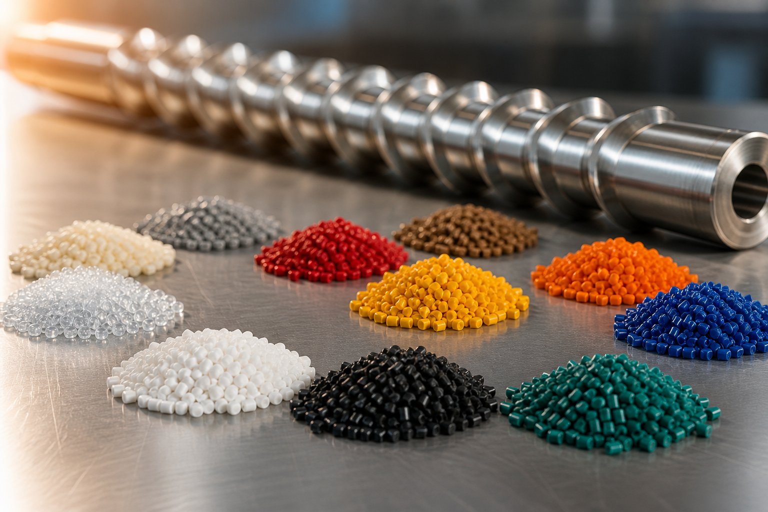
A single screw extruder machine is not a universal tool — it's a platform whose performance depends entirely on how well its screw geometry, barrel lining, and temperature profile match the specific polymer it processes. Two extruders with identical specifications can produce dramatically different results if one is configured for HDPE and the other is fed rigid PVC. The resin dictates the rules: melting behavior, thermal sensitivity, viscosity profile, and abrasive content all demand a tailored approach. This section maps the most common polymer families to the screw designs and barrel configurations that deliver optimal results — the kind of material-machine compatibility framework that rarely appears in supplier documentation.
The underlying principle is straightforward. Crystalline polymers — PE, PP, PET, nylon — have a distinct melting point where they transition abruptly from solid to liquid. That sharp transition demands a longer, more gradual compression zone to avoid sudden pressure spikes and unmelted solids. Amorphous polymers — PS, ABS, polycarbonate, flexible PVC — soften progressively over a wide temperature range, allowing shorter and more aggressive compression sections. Every screw design recommendation in this guide traces back to that fundamental distinction.
Polyolefins and Commodity Resins
Polyolefins — HDPE, LDPE, LLDPE, and polypropylene — represent the largest volume of polymer extrusion equipment output worldwide. They're forgiving to process, tolerant of moderate shear, and well-suited to standard metering screws with moderate compression ratios in the 2.5:1 to 4.0:1 range. HDPE, being highly crystalline, benefits from a longer compression zone and higher compression ratios (3.0:1 to 4.0:1) to handle its sharp melting transition and lower bulk density. LDPE and LLDPE, with their branched molecular structures, melt more easily and process well at 2.5:1 to 3.5:1.
For high-output polyolefin lines — particularly HDPE pipe and blown film — barrier flight screws (Barr type) paired with grooved feed zones deliver the best combination of throughput and melt quality. A Maddock or pineapple mixing section near the screw tip improves temperature homogeneity without excessive shear. Standard nitrided barrels are perfectly adequate for unfilled polyolefins, keeping polymer extruder machine operating costs low.
Styrenics — polystyrene, ABS, and SAN — fall into a similar ease-of-processing category. Their amorphous structure means they soften gradually, tolerating shorter compression zones and lower compression ratios (2.0:1 to 2.5:1 for PS; 1.6:1 to 2.5:1 for ABS). General-purpose screw geometry handles these materials well, though ABS benefits from a mixing section to ensure uniform melt temperature across the channel.
Heat-Sensitive Materials Like PVC
PVC occupies a category of its own. It's thermally sensitive — processing temperatures sit dangerously close to its degradation temperature, and overheating releases hydrochloric acid gas that corrodes equipment and poses health risks. Every aspect of the polymer extruder machine configuration must reflect this constraint.
Successful PVC extrusion requires low-shear, low-compression screw designs — typically 1.8:1 to 2.5:1 compression ratios — with precise, zone-by-zone temperature control. Barrel temperatures are kept as uniform as possible, and screw speeds run lower than for polyolefins to minimize viscous dissipation. Mixing elements, if used at all, should be distributive types like pin mixers rather than high-shear dispersive sections. The barrel lining must resist corrosion from HCl; nickel-based alloy liners are standard for PVC production lines.
PET and nylon present different challenges. Both are hygroscopic — they absorb atmospheric moisture that causes hydrolytic degradation during melt processing. Pre-drying to moisture levels below 0.02% (for PET) is essential, and many processors add a vented two-stage screw as insurance. PET's high crystallinity demands gradual compression (2.5:1 to 3.5:1) and longer L/D ratios (28:1 to 33:1). A polyester extruder line typically incorporates barrier screws with Maddock mixers to ensure complete melting and thermal uniformity. Nylon follows a similar pattern — high compression ratios (3.5:1 to 3.7:1), pre-drying, and potentially vented screws for grades with residual moisture or volatile additives.
Filled, Reinforced, and Recycled Compounds
The moment you introduce mineral fillers, glass fiber, or recycled content, the rules change. Calcium carbonate, talc, and glass fiber are abrasive — they erode standard nitrided barrels and screw flights at rates that can halve component life compared to unfilled resin processing. Bimetallic barrel linings (iron-boron for moderate abrasion, tungsten-carbide for glass-filled compounds) and hardfaced screw flights become non-negotiable. Mixing sections — typically a combination of barrier flights for complete melting and distributive elements for filler distribution — ensure the reinforcement is spread uniformly rather than concentrated in streaks.
Recycled and post-consumer resins bring a different set of complications: variable moisture content, mixed polymer contamination, volatile residues, and inconsistent melt flow index. Vented two-stage screws are the standard recommendation, allowing volatile extraction during processing without the need for energy-intensive pre-drying. Robust screen packs and continuous screen changers handle the higher contaminant loads typical of post-consumer streams. As Plastics Technology notes, processors moving to post-consumer reclaim should expect to use tighter filtration that elevates head pressure — a factor that must be accounted for in the second-stage screw design to prevent vent flooding.
Rubber and elastomer extrusion represents a related but distinct discipline. A rubber extruder machine operates at significantly lower temperatures than thermoplastic equipment — typically 60 to 120°C — because the goal is to shape the compound without initiating premature vulcanization (a phenomenon called "scorch"). Screws for rubber extruding machines use very deep channels, low compression ratios, and specialized feed section designs to handle the high-viscosity, non-melting feedstock. Barrel cooling capacity is often more critical than heating capacity. While the mechanical principles overlap with thermoplastic extrusion, the process control philosophy is fundamentally different, and equipment designed for one is rarely interchangeable with the other.
Polymer-to-Screw Configuration Reference
| Polymer Type | Recommended Screw Design | Compression Ratio | Barrel Lining | Key Processing Notes |
|---|---|---|---|---|
| HDPE | Barrier flight (Barr type) + Maddock mixer; grooved feed for high output | 3.0:1 - 4.0:1 | Standard nitrided | High crystallinity; sharp melting point; long compression zone; benefits from grooved feed |
| LDPE / LLDPE | Standard metering or barrier flight + distributive mixer | 2.5:1 - 3.5:1 | Standard nitrided | Easier to melt than HDPE; moderate shear tolerance; watch for melt fracture at high rates |
| PP | Standard metering or barrier flight + mixing section | 2.5:1 - 3.5:1 | Standard nitrided | Similar to HDPE but slightly lower compression; sensitive to oxidation at elevated temps |
| Rigid PVC | Low-shear metering screw; pin mixer only; no dispersive sections | 1.8:1 - 2.5:1 | Nickel-alloy (corrosion resistant) | Thermally sensitive; low screw speed; precise temperature control; HCl corrosion risk |
| Flexible PVC | Low-compression screw with pin mixer; short compression zone | 2.0:1 - 2.5:1 | Nickel-alloy (corrosion resistant) | High plasticizer content reduces viscosity; very shear-sensitive; avoid Maddock mixers |
| PS / HIPS | General-purpose metering screw | 2.0:1 - 2.5:1 | Standard nitrided | Amorphous; softens gradually; easy to process; watch for degradation at long residence times |
| ABS | General-purpose or barrier screw + mixing section | 1.6:1 - 2.5:1 | Standard nitrided | Amorphous; moderate shear sensitivity; benefits from mixing section for temperature uniformity |
| PET | Barrier flight + Maddock mixer; vented two-stage for undried feedstock | 2.5:1 - 3.5:1 | Standard nitrided or bimetallic for recycled grades | Must pre-dry to <0.02% moisture; high melt temp (~270-290°C); hydrolytic degradation risk |
| Nylon (PA6, PA66) | Barrier flight + mixer; vented screw recommended | 3.5:1 - 3.7:1 | Standard nitrided | Hygroscopic; requires pre-drying; high compression ratio for sharp crystalline melt transition |
| Glass-Filled Compounds | Barrier + distributive mixer; hardened flights | 2.0:1 - 3.0:1 | Tungsten-carbide bimetallic | Highly abrasive; hardfaced flights essential; avoid excessive shear that breaks fiber length |
| Mineral-Filled Compounds | Standard or barrier + mixing section; hardened flights | 2.5:1 - 3.5:1 | Iron-boron or tungsten-carbide bimetallic | Abrasive; filler loading drives lining selection; distributive mixing for uniform dispersion |
| Recycled / Post-Consumer Resin | Vented two-stage screw + robust screen pack | 2.5:1 - 3.5:1 (per stage) | Bimetallic (application-dependent) | Variable moisture and contamination; continuous screen changer recommended; elevated head pressure |
| Rubber / Elastomers | Deep-channel, low-compression cold-feed screw | 1.2:1 - 1.5:1 | Hardened or nitrided; enhanced cooling | Low temps (60-120°C) to prevent scorch; high viscosity; barrel cooling critical; not interchangeable with thermoplastic equipment |
The table above represents starting-point configurations — the polymer extrusion equipment equivalent of a recipe. Real-world optimization always involves adjustments based on specific grade properties, throughput targets, and downstream die geometry. A PP homopolymer and a PP random copolymer, for instance, share the same polymer family row but may need noticeably different compression profiles and temperature settings.
Matching material to machine is a one-time engineering decision. Keeping that match performing over months and years of production, however, requires understanding how wear, degradation, and process drift erode the carefully engineered clearances and surface conditions that make all of these configurations work — a maintenance reality that most equipment guides conveniently overlook.
Maintenance, Wear Patterns, and Troubleshooting
Even a perfectly matched screw-and-barrel combination won't stay perfect forever. From the moment the screw begins rotating inside the barrel, wear begins — and the original clearances that make the pumping mechanism work start to open up. That opening is slow, often invisible, and almost always underestimated. Operators compensate with incremental process adjustments — a few more RPM here, a degree or two of barrel temperature there — and the line keeps running. But those tweaks mask a gradual decline in melt quality, throughput, and energy efficiency that eventually reaches a tipping point. Understanding what wears, why it wears, and how to detect it before it becomes a crisis is what separates proactive maintenance from expensive emergency shutdowns.
Recognizing Screw and Barrel Wear
Three distinct wear mechanisms attack the screw and barrel of a single screw extruder machine, often simultaneously. Each leaves a different signature and demands a different material response.
Adhesive wear occurs when metal surfaces — the screw flight land and the barrel bore — make direct contact. High localized stresses cause the surfaces to momentarily weld together and then fracture apart. You'll recognize adhesive wear by a burr or "rolling over" of the trailing edge of the flight land, scoring on the barrel I.D., or hardfacing material that appears gouged or missing from the flight tips. Misalignment between the barrel and the drive system is a primary contributor — and it's remarkably common. Screw deflection caused by solids wedging, where unmelted material plugs the channel and forces the screw against the barrel wall, also triggers adhesive wear in predictable patterns.
Abrasive wear is the most prevalent form in plastics processing. Every pellet sheared and compressed against the barrel wall removes a microscopic amount of metal. With unfilled polymers, this process is slow — barrels and screws can last years. Introduce glass fiber, calcium carbonate, talc, flame retardants, or regrind containing metal fragments, and the wear rate accelerates dramatically. Aggressive fillers can reduce screw and barrel useful life by 50% or more compared to unfilled processing. Abrasive wear typically shows up first on the flight lands and the barrel wall in the compression zone, where pressures and material movement against metal are highest.
Corrosive wear results from chemical attack by the polymer melt itself. PVC releases hydrochloric acid during processing; fluoropolymers produce hydrofluoric acid; certain flame-retardant additives generate corrosive byproducts. Corrosion oxidizes the metal surface, weakening it and making it vulnerable to accelerated mechanical wear. Components with high iron content are especially susceptible. If you're running PVC or halogenated compounds on a standard nitrided barrel without a corrosion-resistant alloy liner, you're essentially dissolving your barrel from the inside out.
Detecting wear before it reaches critical levels requires periodic measurement. Bore gauging — inserting a precision gauge into the barrel to measure inside diameter at multiple points along its length — reveals localized enlargement patterns. Screw flight micrometer readings measure the outside diameter of the flight lands to detect material loss. Compare current measurements against the original manufacturer's dimensions. The standard rule: when the diametral clearance between screw flight and barrel bore doubles from its original specification, melting efficiency has degraded enough to justify action. For a 90 mm screw with an original clearance of 0.09 mm per side, that means intervention at around 0.18 mm per side — a gap invisible to the eye but measurable in scrap rate and energy cost.
On larger machines where pulling the screw for measurement isn't practical on a regular schedule, tracking operational parameters serves as a proxy. Record screw speed, barrel temperatures, motor amps, head pressure, and output rate. When you notice that maintaining the same output requires progressively higher RPM, elevated barrel temperatures, or increased backpressure, wear is the likely culprit — even if the product still looks acceptable. Industry experts describe this as a "point of diminishing returns" where each incremental process adjustment delivers less benefit and costs more energy.
Common Extrusion Defects and Root Causes
Worn components create measurable defects — but wear isn't the only villain. Many of the most frustrating extrusion problems trace back to process settings, screw design mismatches, or feed inconsistencies that mimic wear symptoms. The troubleshooting framework below pairs each common defect with its most likely root causes and corrective actions, so you can distinguish between a maintenance problem and a process problem before shutting down the line.
- Melt surging (cyclic pressure and dimensional fluctuation): Surging — periodic swings in die pressure that produce wall-thickness or weight variation in the finished product — is one of the most common complaints on aging single screw extrusion lines. Root causes include screw and barrel wear that allows melt to leak backward over the flights, inconsistent solids conveying due to hopper bridging or a worn feed throat, and a compression zone mismatched to the resin's melting behavior. Corrective actions: measure screw and barrel clearances, inspect the feed system for obstructions, verify consistent pellet size and bulk density, and evaluate whether the screw geometry matches the current resin grade.
- Melt fracture (surface roughness, sharkskin, or distortion): When the melt exits the die at shear rates exceeding the polymer's critical threshold, the surface breaks into patterns ranging from fine roughness ("sharkskin") to gross distortion. Root causes: die land too short, die gap too narrow, melt temperature too low (increasing viscosity and shear stress), or excessively high output rate for the die design. Corrective actions: raise melt temperature slightly, reduce screw speed, increase die gap or land length, or apply a processing aid to reduce die-wall friction.
- Poor mixing, gels, or unmelted particles: Gels appear as small, translucent specks or streaks in the finished product — unmelted or incompletely sheared polymer that survived the compression and metering zones. Root causes: insufficient compression ratio for the material, worn screw that has lost channel depth and shear capability, absence of a mixing section, or melting shifting downstream due to wear-related geometry changes. Corrective actions: inspect screw for flight wear and channel depth loss, add or upgrade the mixing section, verify that the compression ratio matches the resin, and check the screen pack for bypass.
- Polymer degradation (discoloration, black specks, burning odor): Thermal degradation shows up as yellowing, brown streaks, or black specks — carbonized polymer that has spent too long at too high a temperature. Root causes: excessive barrel temperature, dead spots in the die adapter or breaker plate where polymer stagnates, residence time too long due to oversized machine running at low throughput, or shear overheating from too-high screw speed. Corrective actions: reduce barrel temperatures in the metering and die zones, reduce screw RPM, inspect the adapter and breaker plate for flow stagnation, and ensure the machine is appropriately sized for the production rate.
- Feed inconsistencies (throughput drops, output variation): When the extruder's output rate fluctuates randomly rather than cyclically, the problem usually originates at the feed end. Root causes: material bridging in the hopper, feed-throat cooling failure allowing premature melting, inconsistent regrind particle size, or moisture causing pellets to stick together. Corrective actions: clean and inspect the hopper and feed throat, verify cooling water flow and temperature, ensure consistent feedstock particle size and dryness, and consider force-feeding for problematic materials.
A pattern emerges across nearly every defect: the root cause frequently points back to screw geometry and its relationship to the barrel bore. As melt processing specialists emphasize, when wear changes the screw's geometry, melting relocates and the process becomes unstable — even if temperature setpoints remain identical to what worked six months ago. Adjusting process parameters can temporarily mask the symptom, but only restoring the original screw-to-barrel clearance addresses the cause.
When to Replace vs Refurbish Barrels and Screws
Every used extruder eventually faces this decision. The choice between refurbishment and replacement hinges on how far the wear has progressed and whether the original geometry can be economically recovered.
Refurbishment makes sense when wear is moderate and hasn't fundamentally altered the screw's melting or pumping behavior. Screw flights can be rebuilt through hardfacing — applying tungsten-carbide or stellite overlays to worn flight tips, then grinding them back to the original diameter. Cost-effective repair options can save up to 40% compared to new screws, and techniques like re-chroming, nitriding, or hard-surfacing extend useful life significantly. Barrels can be re-bored to a slightly larger diameter and fitted with a new screw machined to match, though this approach has limits — each re-bore removes more base material and eventually compromises the barrel's pressure-containing wall thickness.
Replacement becomes the right call when wear has changed the screw's compression ratio, shifted the melting location downstream, or enlarged the barrel bore beyond the re-bore limit. Indicators that tip the decision toward replacement include: rising motor load and energy consumption with no corresponding output increase, inability to maintain stable melt pressure despite repeated process adjustments, and product quality variation that returns immediately after every "fix." At this point, even minimal wear can reduce efficiency by over 50%, making continued operation far more expensive than the replacement itself.
Barrel and screw replacement is, in fact, the single most impactful maintenance action for restoring output quality and energy efficiency on aging lines. It resets the leakage path, restores the designed compression ratio, and recovers the shear profile that your process was originally tuned around. For operators running used extrusion equipment or used plastic extruders — machines acquired without full maintenance histories — this action is often the first step toward consistent, predictable production.
The practical challenge is sourcing replacement components that match your existing machine precisely. Single screw extruder manufacturers typically supply OEM barrels and screws, but lead times can be long and costs high — especially for older or discontinued models. This is where specialized extruder manufacturers focused on replacement components fill a critical gap. Suppliers like NANHAIYA, for example, engineer custom replacement single screw barrels matched to existing machine models using OEM drawings, physical samples, or field-measured dimensions. This capability serves pipe, film, sheet, pelletizing, and recycling producers who need to restore worn used extruder equipment to original performance specifications without investing in entirely new machines.
Whether you refurbish or replace, the maintenance cycle doesn't end with installation. New components require proper alignment verification, compatible metallurgy between screw hardfacing and barrel lining, and a documented baseline of dimensional measurements that future inspections can reference. The goal isn't just to fix the immediate problem — it's to establish a predictive maintenance rhythm that catches the next wear cycle before it reaches the point of diminishing returns, keeping your line running at peak efficiency instead of gradually drifting away from it.
Maintaining existing equipment is one half of the operational equation. The other half — knowing how to select the right extruder in the first place, whether buying new or sourcing used extruder equipment — determines whether your maintenance burden stays manageable or becomes a recurring burden that no amount of component replacement can overcome.
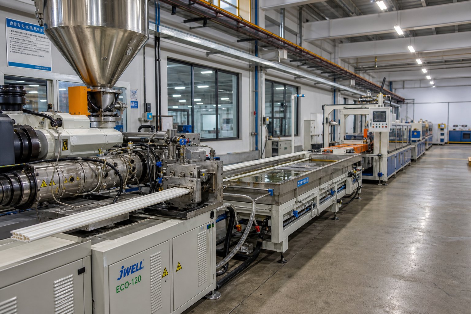
How to Choose the Right Single Screw Extruder for Your Line
Knowing the components, screw geometry, material compatibility, and wear patterns gives you the technical vocabulary to evaluate equipment intelligently. But vocabulary alone doesn't answer the question every processor ultimately faces: which machine should I actually buy? The gap between understanding extrusion theory and making a sound capital equipment decision is where most buyers stumble — and where the wrong choice locks you into years of suboptimal throughput, excessive energy costs, or premature wear that no amount of process tweaking can fix.
A systematic, step-by-step evaluation eliminates guesswork. Rather than starting with a supplier's catalog and working backward, start with your production requirements and let them drive every specification forward.
Defining Output Requirements and Material Needs
The selection process begins not with the machine, but with the product leaving the end of the line. What are you making — pipe, blown film, cast sheet, profiles, pellets? Each product dictates a different die configuration, different downstream equipment, and different demands on the extruder's melt quality and pressure consistency. A pipe line needs rock-steady die pressure and uniform melt temperature to hold wall-thickness tolerances. A blown film line demands a melt with no gels, excellent thermal homogeneity, and precise output control. A pelletizing line prioritizes throughput volume above surface finish.
Follow this framework to move from product definition to machine specification:
- Define the end product and its critical quality parameters. Identify the product geometry (pipe, film, sheet, profile, pellet), the dimensional tolerances you must hold, and any surface-quality or mechanical-property requirements that will constrain the process window.
- Identify the primary resin and any secondary materials. Determine the base polymer (HDPE, PP, PVC, PET, etc.), whether fillers or reinforcements are involved, and whether you'll process masterbatch, additives, or recycled content. This step directly determines the screw design family — barrier, vented, grooved feed, or general purpose — and the barrel lining metallurgy.
- Establish the required throughput range in kg/hr. Define three numbers: the minimum output during slow periods or changeovers, the nominal rate for standard production, and the maximum rate for peak demand or future growth. As extrusion sizing engineers recommend, the maximum should not exceed 80% of the extruder's mechanical limit — leaving headroom for process stability and future capacity.
- Select the screw diameter based on throughput. Use the nominal throughput to identify the appropriate diameter class. For polyolefins, standard production diameters of 45 to 90 mm cover 50 to 450 kg/hr; high-volume lines running 800 to 2,000+ kg/hr require 120 to 150 mm or larger. Resist the temptation to oversize — an extruder designed for 1,000 kg/hr running at 300 kg/hr suffers from extended residence times, poor shear, and thermal degradation.
- Determine the L/D ratio based on processing complexity. Straightforward melting of a single unfilled polymer works at 24:1 to 25:1. Barrier screws with mixing sections typically need 28:1 to 30:1. Vented two-stage designs or heavily filled compounds demand 33:1 to 36:1. Match the ratio to the functional zones your screw must accommodate.
- Specify the screw geometry and compression ratio for your resin. Use the material compatibility data covered earlier — crystalline resins need higher compression ratios and longer compression zones; amorphous and thermally sensitive materials require the opposite. Factor in whether you need barrier flights, mixing sections, or vented stages.
- Evaluate motor power and drive system requirements. Calculate the specific energy consumption for your polymer (typically 0.15 to 0.30 kWh/kg for polyolefins, higher for engineering resins) and multiply by your target throughput to establish the minimum motor power. Add a safety margin — a gearbox service factor of 1.5 or higher is standard for heavy-duty continuous extrusion.
- Match the machine to available floor space, utilities, and infrastructure. Confirm that the selected extruder physically fits your facility, that electrical supply can handle the motor's starting and running current, that cooling water capacity is adequate for the barrel, feed throat, and downstream equipment, and that material handling systems can deliver consistent feed to the hopper.
Skipping any step in this sequence leads to the two most common sizing errors: oversizing, which causes thermal degradation and energy waste at low utilization, or undersizing, which forces the machine to its limits and accelerates wear on every component.
Evaluating New, Used, and Refurbished Equipment
Budget realities rarely allow every processor to buy new, purpose-built equipment. The market for used single screw extruders and refurbished lines is substantial — and for many operations, it's the smartest path to production capacity. Each acquisition route carries distinct trade-offs worth understanding before you start browsing a plastic extruder machine for sale.
New Equipment
Buying new gives you current safety features, precise screw geometry matched to your resin, full warranty coverage, and the latest drive and control technology. The downside is cost — a new production-grade single screw extruder can range from $50,000 for a small lab unit to well over a million dollars for large, high-speed configurations, before shipping, installation, and downstream equipment. Lead times can stretch months, especially for custom screw designs and bimetallic barrels.
Used Equipment
Searching for used extruders for sale — whether through dealers, auctions, or direct from closing facilities — can cut acquisition costs by 40 to 60 percent. The risk is uncertainty: unknown wear history, outdated controls, missing documentation, and screw geometry that may not match your material. When evaluating a plastic extrusion machine for sale on the secondary market, always request bore gauge measurements and screw flight readings before committing. A machine with a worn barrel and screw may look like a bargain until you add the cost of replacement components.
Refurbished Equipment
Refurbished machines — inspected, re-painted, re-wired, and fitted with rebuilt or new wear components — sit between new and used in both cost and risk. A well-refurbished extruder can deliver near-new performance at 50 to 70 percent of new-machine cost. The key is verifying that the refurbishment addressed the components that actually wear — the screw, barrel bore, gearbox bearings, and heater bands — and not just the cosmetics.
There's also a fourth path that many processors overlook: upgrading an existing machine rather than replacing it entirely. Operators who already own an extruder but need improved wear resistance, a different compression profile for a new resin, or restored dimensional tolerances can work with specialized barrel suppliers. NANHAIYA, for example, engineers replacement single screw barrels matched to specific machine models using OEM drawings, physical samples, or field-measured dimensions — a practical option for pipe, film, sheet, pelletizing, and recycling producers upgrading performance or switching material families without the capital outlay of entirely new extrusion equipment for sale. This approach is especially valuable for processors running older machines where original manufacturer support has diminished or lead times have become impractical.
Building a Complete Extrusion Line Beyond the Extruder
Here's the mistake that catches even experienced buyers: evaluating the extruder in isolation. The extruder is only one link in a production chain, and its output quality is only as good as the weakest station downstream. A perfectly sized 90 mm extruder producing 300 kg/hr of flawless melt is useless if the cooling bath is too short to solidify the product at line speed, or if the haul-off can't maintain consistent tension.
A complete extrusion line includes everything from the hopper to the end-of-line collection system. Beyond the extruder itself, you need to evaluate:
- Die and die adapter — matched to the product geometry and the extruder's output pressure and flow rate. A die designed for 200 kg/hr will not scale to 400 kg/hr simply by running the extruder faster.
- Calibration and sizing equipment — vacuum tanks for pipe, sizing blocks for profiles, air rings for blown film. These stations lock the geometry while the product is still hot and deformable. Undersized calibration is one of the most common downstream bottlenecks.
- Cooling systems — spray tanks, immersion baths, or air cooling, depending on the product. The cooling section must remove heat at the same rate the extruder produces output. Increasing extruder throughput without extending cooling capacity results in products that look correct at the cutter but deform after stacking or coiling.
- Haul-off (puller) — sets the line speed and directly controls wall thickness through the relationship between pull rate and extruder output. Speed oscillations in the haul-off create repeating thickness patterns that are often misdiagnosed as extruder problems.
- Cutting, winding, and collection — planetary cutters for rigid pipe, flying saws for profiles, coilers for flexible tubing. Winding tension that's too high stretches the product; too low produces unstable coils. These stations determine the delivery form your customers receive.
When sourcing extrusion equipment for sale — whether new or used — always evaluate the entire line as a matched system. A high-performance extruder paired with inadequate downstream equipment creates a bottleneck that negates the extruder's capability. Conversely, upgrading downstream stations on an existing line can sometimes unlock throughput gains that rival the impact of a new extruder at a fraction of the cost.
The best extruders for thermoplastics aren't simply the machines with the highest specs — they're the ones whose diameter, L/D ratio, screw geometry, and drive system align precisely with the product, polymer, and throughput your business actually requires. Start with your production needs, work systematically through the selection framework, evaluate the full line as an integrated system, and you'll make an equipment decision that delivers return on investment for years rather than regret within months.
Frequently Asked Questions About Single Screw Extruder Machines
1. What is the difference between a single screw and twin screw extruder?
A single screw extruder uses drag flow — relying on friction between the polymer and barrel wall — to convey and melt material, making it ideal for steady-state production of pre-compounded resins into pipes, films, sheets, and profiles. A twin screw extruder uses two intermeshing screws that create positive displacement, offering superior mixing and the ability to decouple throughput from screw speed. Single screw systems handle 70-80% of global thermoplastic extrusion due to lower purchase cost, simpler maintenance, and sufficient mixing for most commodity and engineering polymers. Twin screw systems justify their 40-165% higher price when the extruder must perform compounding, reactive extrusion, or heavy devolatilization tasks.
2. How do I choose the right screw design for my polymer?
Screw selection starts with understanding whether your polymer is crystalline or amorphous. Crystalline resins like HDPE and nylon melt sharply and need longer compression zones with higher compression ratios (3.0:1 to 4.0:1), often paired with barrier flight screws for complete melting. Amorphous resins like PS and ABS soften gradually and tolerate shorter compression zones at lower ratios (1.6:1 to 2.5:1). Heat-sensitive materials like PVC require low-shear, low-compression designs with pin mixers only. Filled compounds need hardfaced flights and abrasion-resistant barrel linings. Specialized suppliers such as NANHAIYA can engineer custom single screw barrels matched to your specific machine model and resin requirements using OEM drawings, samples, or measured dimensions.
3. What does the L/D ratio mean on a single screw extruder?
The L/D (length-to-diameter) ratio expresses the screw's effective working length as a multiple of its diameter. A 90 mm screw with a 30:1 L/D has 2,700 mm of active processing length. Shorter ratios (20:1 to 24:1) suit simple melting of single unfilled polymers on pipe or profile lines. Mid-range ratios (25:1 to 30:1) accommodate barrier screws with mixing sections for filled compounds or color blending. Longer ratios (30:1 to 36:1) are necessary for vented two-stage screws or demanding mixing applications. Longer is not always better — excessive L/D increases residence time, which degrades thermally sensitive polymers like PVC, and raises manufacturing costs due to tighter machining tolerances.
4. How do I know when to replace the screw and barrel on my extruder?
Monitor the diametral clearance between the screw flight outer diameter and the barrel bore using bore gauges and flight micrometers. When that clearance doubles from the original specification, melting efficiency has degraded enough to warrant action. Operational signs include needing progressively higher RPM or barrel temperatures to maintain the same output, rising motor amperage without throughput gains, unstable melt pressure, and recurring product defects like gels or dimensional variation. Refurbishment — hardfacing flights and re-chroming — is cost-effective when wear is moderate, saving up to 40% versus new components. Full replacement is justified when the compression ratio has shifted or the barrel bore exceeds its re-bore limit.
5. What are barrier flight screws and when should I use them?
Barrier flight screws add a secondary flight in the compression zone that physically separates the solid bed from the melt pool. As polymer melts against the barrel wall, it flows over the barrier into a dedicated melt channel while unmelted solids are retained until fully molten. Two main types exist: Maillefer (crossing) barriers work well for lower-energy polymers and materials with fragile solid beds, while Barr (parallel) barriers offer roughly 33% more solids-channel surface area and excel with high-energy polymers like HDPE, PET, and nylon. Barrier screws significantly improve melting efficiency and throughput consistency, but they must be designed for your specific material — a mismatched barrier geometry can cause solid-bed plugging and worsen surging.
Written by
Nanhaiya Technical Team
Zhoushan Nanhaiya Plastic Machinery Co., Ltd.
The Nanhaiya technical team supports screw and barrel manufacturing projects through application review, technical communication, custom manufacturing coordination, and production and quality control.
Discuss Your Application
Related Articles
More insights on screw barrel technology and plastics processing.

What Nobody Tells You About Screw Barrel For Plastic Machine Design
Oct 10, 2026
Learn how screw barrel for plastic machine design affects melt quality, throughput, and wear life. Covers geometry, resin matching, troubleshooting, and sourcing.
Read Article
Single Screw Extruder for Sheet: Stop Guessing, Start Specifying
Oct 9, 2026
Learn how to specify a single screw extruder for sheet production. Covers screw geometry, resin-specific processing, troubleshooting, and maintenance best practices.
Read Article
PE Pipe Extruder Machine: What Datasheets Won't Tell You
Oct 9, 2026
Learn how a PE pipe extruder machine works, key specs explained, material grade selection, maintenance tips, and buyer guidance beyond the datasheet.
Read ArticleLooking for something else?
Search by material, symptom or product and jump straight to the relevant page.
These are navigation suggestions based on keyword matching — not a quotation, not a delivery commitment, and not a substitute for engineering review. Final specification is confirmed by our engineers against your drawings and processed material.
Need help with screw barrel selection?
Share your machine model, processed material and application. Our team can help with pricing and technical support.